EP2223403B1 - Fault direction determination - Google Patents
Fault direction determination Download PDFInfo
- Publication number
- EP2223403B1 EP2223403B1 EP07848098.5A EP07848098A EP2223403B1 EP 2223403 B1 EP2223403 B1 EP 2223403B1 EP 07848098 A EP07848098 A EP 07848098A EP 2223403 B1 EP2223403 B1 EP 2223403B1
- Authority
- EP
- European Patent Office
- Prior art keywords
- fault
- measured voltage
- phase
- voltage
- time interval
- Prior art date
- Legal status (The legal status is an assumption and is not a legal conclusion. Google has not performed a legal analysis and makes no representation as to the accuracy of the status listed.)
- Active
Links
Images


Classifications
-
- H—ELECTRICITY
- H02—GENERATION; CONVERSION OR DISTRIBUTION OF ELECTRIC POWER
- H02H—EMERGENCY PROTECTIVE CIRCUIT ARRANGEMENTS
- H02H3/00—Emergency protective circuit arrangements for automatic disconnection directly responsive to an undesired change from normal electric working condition with or without subsequent reconnection ; integrated protection
- H02H3/38—Emergency protective circuit arrangements for automatic disconnection directly responsive to an undesired change from normal electric working condition with or without subsequent reconnection ; integrated protection responsive to both voltage and current; responsive to phase angle between voltage and current
- H02H3/382—Emergency protective circuit arrangements for automatic disconnection directly responsive to an undesired change from normal electric working condition with or without subsequent reconnection ; integrated protection responsive to both voltage and current; responsive to phase angle between voltage and current involving phase comparison between current and voltage or between values derived from current and voltage
Definitions
- the present invention relates to the field of electrical power systems.
- the invention more particularly relates to a method and computer program product for determining the direction of fault in an electrical power system as well as to a fault handling device which provides such fault direction determination.
- Such a device is normally connected to a measurement node of the electrical power system, where the measurement node may be provided in a power line.
- the measurement node may be provided in a power line.
- the present invention is therefore directed towards providing an improved determination of the direction of fault in an electrical power system.
- One object of the present invention is therefore to provide an improved method for determining the direction of fault in an electrical power system.
- This object is according to a first aspect of the present invention achieved through a method for determining the direction of fault in an electrical power system comprising the steps of:
- Another object of the present invention is to provide a fault handling device in an electrical power system, which provides an improved determination of the direction of fault.
- This object is according to a second aspect of the present invention achieved through a fault handling device in an electrical power system and comprising:
- Another object of the present invention is to provide a computer program product for determining the direction of fault in an electrical power system in an improved way.
- This object is according to a third aspect of the present invention achieved through a computer program product for determining the direction of fault in an electrical power system and comprising computer program code provided on a computer readable medium and arranged to make a fault handling device in the electrical power system when the code is loaded into the device:
- the present invention has the advantage of providing a safer determination of the direction of fault in an electrical power system.
- the invention more particularly enables the provision of a correct determination of the direction of fault when the fault causes voltage inversion.
- the invention also avoids slow changes in phase of a measured voltage that are indicative of power swings to influence the determination of direction of the fault. Because of this the probability is raised of selecting a correct action relating to the fault.
- Fig. 1 schematically shows a section of an electrical power system 8 comprising a power line 10.
- a measurement node 11 To this measurement node 11 there is connected a fault handling device 12 according to the present invention.
- the power line 10 is used to transfer electrical power, which is typically electrical AC power.
- stages that may be included are omitted, such as transformer stations and additional power lines.
- To the system 8 there may furthermore be connected one or more loads.
- a measurement node need furthermore not be connected to a power line, but may be connected to another entity of the power system. It should furthermore be realised that there may be normally several measurement nodes and fault handling devices in relation to such a system.
- a fault handling device 12 is in these types of systems furthermore often called a protection relay.
- Fig. 2 shows a block schematic of the fault handling device 12 according to the present invention.
- the device 12 includes a voltage detecting unit 14 and a current detecting unit 16, where the voltage detecting unit 14 is arranged to measure the voltage V of the power line and the current detecting unit 16 is arranged to measure the current C of the power line at the measurement node.
- the voltage detecting unit 14 is furthermore connected to a store 18, to a fault detecting unit 19, to a fault direction determining unit 20, to a distance determining unit 22 and to a fault handling decision unit 24.
- the current detecting unit 16 is connected to the fault detecting unit 19, to the fault direction determining unit 20, to the distance determining unit 22 and to the fault handling decision unit 24.
- the fault detecting unit 19 is also connected to the fault direction determining unit 20, to the distance determining unit 22 and to the fault handling decision unit 24.
- the fault direction determining unit 20 is also connected to the store 18 and to the fault handling decision unit 24.
- the distance determining unit 22 is connected to the fault handling decision unit 24.
- the fault handling decision unit 24 may furthermore emit a control signal CTRL. What this signal may be used to control will shortly be described.
- Fig. 3 schematically shows a number of circuit breaking units 26, 28, 30 and 32 provided in the power line 10 of fig. 1 .
- the fault handling device 12 is connected to the power line 10 via the measurement node 11.
- a first circuit breaking unit 26 followed by a second circuit breaking unit 28.
- Thereafter follows the measurement node 11 to which the fault handling device 12 is connected.
- a third circuit breaking unit 30 and a fourth circuit breaking unit 32, where the fourth circuit breaking unit 32 is shown furthermost to the right in fig. 3 .
- the various circuit breaking units 26, 28, 30, 32 may be provided at great distances from each other.
- the circuit breaking units 26, 28, 30, 32 may be provided as power switches or relays.
- the above mentioned control signal CTRL is in fig. 3 shown as being applied to the fourth circuit breaking unit 32 to the right of the measurement node 11.
- the control signal CTRL may be selectively applied to any of the circuit breaking units 26, 28, 30, 32. It is also possible to apply the control signal CTRL to more than one circuit breaking unit. Which one is or which ones are selected depends on where the fault handling device 12 determines that a fault has occurred.
- faults may occur. Such faults may for instance occur because of lightning hitting a point of the power line, in which case current may go from the power line into the ground.
- a voltage is measured and then used as a reference.
- the voltage may here be one of the phase voltages. It may also be a voltage that is derived from the phase voltages, like through a combination of these phase voltages. It may in this case be a so-called positive sequence polarizing voltage, a negative sequence polarizing voltage or a zero sequence polarizing voltage.
- Such a measured reference voltage is then the detected voltage before the fault. If then the distance to the fault is determined it is then easy to determine where various counter measures are to be applied, such as for instance disconnecting the power line. Such a fault may furthermore cause frequency changes and swinging of the system. Such an influence on the system leads to the voltage detected before the fault not being reliable as a reference and that the fault direction being harder to determine. This is especially not good if the fault direction is needed to be monitored some time after the fault has occurred.
- the present invention is provided for addressing this problem.
- fig. 1 - 3 shows a voltage measured at the measurement node before and after a detected fault as well as the relationships between the phases of the voltage before and after the detection of the fault and a phase offset
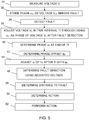
- fig. 5 shows a number of method steps being performed in a method of determining the direction of the fault according to the present invention.
- the voltage detecting unit 14 of the fault handling device 12 continuously detects or measures the voltage of the power line 10 at the measurement node, step 34.
- the voltage V PF being measured before a fault is being detected has a certain shape that varies periodically and then the voltage typically has a sinusoidal shape. It is an AC voltage.
- the fault direction determining unit 20 here stores or makes the voltage detection unit 14 store the phase ⁇ PF of the voltage V PF before a fault and optionally also the amplitude of the voltage V PF in the store 18, step 36.
- the voltage V PF here has a phase ⁇ PF that exists before a fault is detected.
- the fault detecting unit 19 thereafter detects the fault, step 38.
- a fault may be detected in conventional manner and may be detected through changes in the amplitude of the voltage and/or current in the measurement node 11.
- the fault detecting unit 19 thus detects the fault and signals this fact to the fault direction determining unit 20, to the distance determining unit 22 and to the fault handling decision unit 24.
- the fault is here detected at a point in time that in fig. 4 is shown as the beginning of a time interval TI.
- the shape of the measured voltage V here changes, where the change includes a change in amplitude and in phase.
- the phase of the measured voltage V is changed.
- the fault direction determining unit 20 continues to receive measurement voltages V F from the voltage detecting unit 14. It here first adjusts the voltage V F being measured in a time interval TI that follows directly after the detection of the fault, step 39. This adjustment is done through the fault direction determining unit 20 fetching the phase ⁇ PF of the measured voltage V PF before the fault from the store 18 and using this phase ⁇ PF as the phase of the voltage V F during the time interval TI. It thus adjusts the phase of the voltage V F measured in this time interval TI after the detection of the fault to be the same as that before the fault.
- the fault direction determining unit 20 starts to determine the phase ⁇ F of the measured voltage V F after the detection of the fault, step 40. It does this through studying the voltage V F measured during the same time interval TI.
- the time interval TI here has a length that is sufficient for enabling the phase of the measured voltage after the fault to be determined.
- the time interval can here have a length that ranges between 1/10 period of the measured voltage V and 100 periods of the same voltage. The length should at least be 1/10 of the period and is with advantage one period. In the present embodiment the length of the time interval TI equals two periods of the voltage, which enables a safe determination of the phase ⁇ F after the detection of the fault.
- the fault direction determining unit 20 applies and determines a phase offset ⁇ o based on the phase ⁇ PF of the measured voltage V PF before the fault and the phase ⁇ F of the measured voltage V F that is determined at the end of the time interval TI, step 42.
- the phase offset ⁇ o is determined as the difference between the phase ⁇ PF of the measured voltage V PF before the fault and the phase ⁇ F of the measured voltage V F determined at the end of the time interval TI.
- the fault direction determining unit 20 continues to receive measured voltages V F from the voltage detecting unit 14, which measured voltages are thus measured after the end of the time interval TI, and adjusts the phase of these received voltages with the phase offset ⁇ o , step 44. This is here done immediately after the time interval TI has elapsed. This means that at least initially the voltage V F measured after the end of the time interval TI will have the same phase as the voltage V PF had before the fault.
- the phase offset ⁇ o is then continued to be used for adjusting the phase ⁇ F of the voltage V F after the detection of the fault for as long as is necessary, which may be for as long as the fault exists.
- the fault direction determining unit 20 determines the direction of the fault in the measurement node 11 using the adjusted voltage, step 46. It does this in known fashion through obtaining measurements of the current from the current detecting unit 16 and using the voltage as a reference. However in this case the reference is the adjusted measured voltage. Data concerning the fault direction is then provided by the fault direction determining unit 20 to the fault handling decision unit 24.
- the distance determining unit 22 may also determine the distance to the fault, step 48. This may be determined in a known way based on measured voltages and currents.
- the fault direction detecting unit 20 and the distance determining unit 22 may finally emit data indicate of the fault direction and the distance to the fault to the fault handling decision unit 24.
- the fault handling decision unit 24 may determine an action to be performed, step 50, and then perform this action, step 52. The action may be to disconnect a section of the electrical power system at the fault, like for instance the power line at the position of the fault.
- the position of the fault may then be located through knowledge of the distance and the direction that the current is flowing in.
- the fault handling decision unit 24 may therefore select to disconnect the power line 10 at this position and emit a control signal CTRL which causes this disconnection to be made, which position is as an example at the position of the fourth circuit breaking unit 32 in fig. 3 .
- the direction of the fault may be continued to be determined in the above described way for the duration of the fault. If a sudden change of at least one electrical property measured at the measurement node is detected while the fault still exists, such as a sudden change of the phase of the measured voltage, then it is possible to repeat the above mentioned method steps and determine a new offset which new offset is then applied on the measured voltage after the detection of the sudden change in the electrical properties.
- the direction of the fault is important information that is used when determining which actions are to be taken in relation to a fault.
- the direction may then be determined through dividing the current with the voltage.
- one traditional way of determining the direction of fault is to use the reference voltage before the fault.
- the fault may furthermore cause slow changes in phase of the measured voltage that are indicative of power swings. If a correct detection of the fault is to be determined, these changes should not be allowed to influence the detected direction of the fault.
- the direction of the fault is determined through dividing the current with the voltage, they will however have an influence on this determination when the voltage reference is the voltage before the fault.
- the present invention provides a safer determination of the direction of the fault during the duration of the fault, which furthermore raises the probability of selecting the correct action in relation to the fault.
- the fault detecting unit, the fault direction determining unit, the distance determining unit and the fault handling decision unit of the fault handling device may be implemented through one or more processors together with computer program code for performing their functions.
- the program code mentioned above may also be provided as a computer program medium, for instance in the form of one or more data carriers carrying computer program code for performing the functionality of the present invention when being loaded into a fault handling device.
- One such carrier 54, in the form of a CD ROM disc is generally outlined in fig. 6 . It is however feasible with other data carriers, like diskettes, memory sticks or USB memories.
- the computer program code can furthermore be provided as pure program code on an external server and fetched from there for provision in the device that is to receive it.
- the present invention may be varied in a number of ways. It should for instance be mentioned that it is possible to adjust the whole voltage and not just the phase. In this case also the amplitude of the measured voltage is used before and after the detection of the fault. The amplitude after the detection of the fault would then have to be normalised in relation to the amplitude before the fault. It is here possible that the voltage is provided as a waveform or a vector. In such a case the phase of the measured voltage provided before and after the detection of the fault is thus part of a wave representation of the measured voltage or a vector representation of the measured voltage. It is furthermore possible to omit adjustment of the measured voltage during the above mentioned time interval.
- the fault detecting unit may furthermore be provided as a part of any of the fault direction determining unit, the direction determining unit or the fault handling decision unit. Two or more of these units may furthermore be provided together as one unit. It is furthermore possible that decisions concerning actions in relation to a fault are taken centrally in a control section of the electrical power system and that the fault handling device only reports the data to this control section, which then decides on the action, like a disconnection of a section of a power line. In this case the control section thus includes the fault handling decision unit, which is then not a part of the fault handling device of the present invention.
- the fault handling device may therefore only include the fault direction determining unit, where this fault handling device is connected to a voltage detecting unit, to a store and to a fault handling decision unit, possibly remotely. Therefore, while the invention has been described in connection with what is presently considered to be most practical and preferred embodiments, it is to be understood that the invention is not to be limited to the disclosed embodiments, but on the contrary, is intended to cover various modifications and equivalent arrangements. The present invention is thus only to be limited by the following claims.
Landscapes
- Locating Faults (AREA)
- Emergency Protection Circuit Devices (AREA)
Description
- The present invention relates to the field of electrical power systems. The invention more particularly relates to a method and computer program product for determining the direction of fault in an electrical power system as well as to a fault handling device which provides such fault direction determination.
- In the field of electrical power systems it is important to detect and locate faults safely in order to be able to perform necessary measures such as disconnect a section of the system, like to disconnect a power line. The fault handling devices that are used for this are often termed protective relays.
- Such a device is normally connected to a measurement node of the electrical power system, where the measurement node may be provided in a power line. When detecting a fault it is then necessary to determine the direction of fault in relation to the node. The way this has traditionally been done is through measuring and storing the voltage before a fault occurs. Then when a fault is detected this pre-stored voltage is used as a reference voltage together with the measured current to determine the direction of the fault. This direction can then be used in locating the position of the fault in the system. Such a device is for instance described in
US 4,731,689 . - Other known methods for determining the fault direction are disclosed in
US 4,251,766 andUS 4,803,635 . One problem with this approach is that if for instance the power system is set in motion through starting to swing or changing frequency then the reference voltage is unreliable. There is therefore a need for being able to safely determine the direction of the fault in an electrical power system also under these circumstances. - The present invention is therefore directed towards providing an improved determination of the direction of fault in an electrical power system.
- One object of the present invention is therefore to provide an improved method for determining the direction of fault in an electrical power system.
- This object is according to a first aspect of the present invention achieved through a method for determining the direction of fault in an electrical power system comprising the steps of:
- measuring a voltage at a measurement node of the electrical power system, and
- storing at least the phase of the measured voltage before the occurrence of a fault,
- characterised by the further steps of
determining at least the phase of the measured voltage at the end of a time interval following directly after a detection of the fault has been made, - determining a phase offset as the difference between the phase of the measured voltage before the fault and the phase of the measured voltage at the end of the time interval, adjusting the phase of the measured voltage after the detection of the fault with the phase offset, and
- using the adjusted measured voltage in determining the direction of fault in relation to the measurement node.
- Another object of the present invention is to provide a fault handling device in an electrical power system, which provides an improved determination of the direction of fault.
- This object is according to a second aspect of the present invention achieved through a fault handling device in an electrical power system and comprising:
- a fault direction determining unit arranged to
- receive voltage measurements from a voltage detecting unit arranged to measure a voltage at a measurement node of the electrical power system, and
- store at least the phase of the measured voltage before the occurrence of a fault in a store,
- characterised by the fault direction determining unit being further arranged to
- determine at least the phase of the measured voltage at the end of a time interval following directly after a detection of the fault has been made,
- determine a phase offset as the difference between the phase of the measured voltage before the fault and the phase of the measured voltage at the end of the time interval,
- adjust the phase of the measured voltage after the detection of the fault with the phase offset, and
- use the adjusted measured voltage in determining the direction of fault in relation to the measurement node.
- Another object of the present invention is to provide a computer program product for determining the direction of fault in an electrical power system in an improved way.
- This object is according to a third aspect of the present invention achieved through a computer program product for determining the direction of fault in an electrical power system and comprising
computer program code provided on a computer readable medium and arranged to make a fault handling device in the electrical power system when the code is loaded into the device: - receive measurements of a voltage at a measurement node of the electrical power system, and
- store at least the phase of the measured voltage before the occurrence of a fault, characterised by the computer program code being further arranged to make the fault handling device when the code is loaded into the device
- determine at least the phase of the measured voltage at the end of a time interval following directly after a detection of the fault has been made,
- determine a phase offset as the difference between the phase of the measured voltage before the fault and the phase of the measured voltage at the end of the time interval, adjust the phase of the measured voltage after the detection of the fault with the phase offset, and
- use the adjusted measured voltage in determining the direction of fault in relation to the measurement node.
- The present invention has the advantage of providing a safer determination of the direction of fault in an electrical power system. The invention more particularly enables the provision of a correct determination of the direction of fault when the fault causes voltage inversion. The invention also avoids slow changes in phase of a measured voltage that are indicative of power swings to influence the determination of direction of the fault. Because of this the probability is raised of selecting a correct action relating to the fault.
- It should be emphasized that the term "comprises/comprising" when used in this specification is taken to specify the presence of stated features, integers, steps or components, but does not preclude the presence or addition of one or more other features, integers, steps, components or groups thereof.
- The present invention will now be described in more detail in relation to the enclosed drawings, in which:
-
fig. 1 schematically shows an electrical power system including a power line to which a fault handling device is connected, -
fig. 2 shows a block schematic of the fault handling device according to the present invention, -
fig. 3 schematically shows the fault handling device connected to a number of circuit breaking units provided in the power line offig. 1 , -
fig. 4 shows a measured voltage before and after a detected fault as well as the relationship between the phases of the voltage before and after the fault and a phase offset, -
fig. 5 shows a number of method steps being performed in a method of determining the direction of fault according to the present invention, and -
fig. 6 schematically shows a computer program product in the form of a CD ROM disc comprising computer program code for carrying out a method of the present invention. - In the following description, for purposes of explanation and not limitation, specific details are set forth such as particular architectures, interfaces, techniques, etc. in order to provide a thorough understanding of the present invention. However, it will be apparent to those skilled in the art that the present invention may be practiced in other embodiments that depart from these specific details. In other instances, detailed descriptions of well known devices, circuits, and methods are omitted so as not to obscure the description of the present invention with unnecessary detail.
-
Fig. 1 schematically shows a section of anelectrical power system 8 comprising apower line 10. In thepower line 10 there is provided ameasurement node 11. To thismeasurement node 11 there is connected afault handling device 12 according to the present invention. Thepower line 10 is used to transfer electrical power, which is typically electrical AC power. In theelectrical power system 8 infig. 1 stages that may be included are omitted, such as transformer stations and additional power lines. To thesystem 8 there may furthermore be connected one or more loads. A measurement node need furthermore not be connected to a power line, but may be connected to another entity of the power system. It should furthermore be realised that there may be normally several measurement nodes and fault handling devices in relation to such a system. Afault handling device 12 is in these types of systems furthermore often called a protection relay. -
Fig. 2 shows a block schematic of thefault handling device 12 according to the present invention. Thedevice 12 includes avoltage detecting unit 14 and a current detectingunit 16, where thevoltage detecting unit 14 is arranged to measure the voltage V of the power line and the current detectingunit 16 is arranged to measure the current C of the power line at the measurement node. Thevoltage detecting unit 14 is furthermore connected to astore 18, to afault detecting unit 19, to a faultdirection determining unit 20, to adistance determining unit 22 and to a faulthandling decision unit 24. Also the current detectingunit 16 is connected to thefault detecting unit 19, to the faultdirection determining unit 20, to thedistance determining unit 22 and to the faulthandling decision unit 24. Thefault detecting unit 19 is also connected to the faultdirection determining unit 20, to thedistance determining unit 22 and to the faulthandling decision unit 24. The faultdirection determining unit 20 is also connected to thestore 18 and to the faulthandling decision unit 24. Also thedistance determining unit 22 is connected to the faulthandling decision unit 24. The faulthandling decision unit 24 may furthermore emit a control signal CTRL. What this signal may be used to control will shortly be described. -
Fig. 3 schematically shows a number ofcircuit breaking units power line 10 offig. 1 . Also thefault handling device 12 is connected to thepower line 10 via themeasurement node 11. As can be seen in the figure there is in thepower line 10, from left to right, a firstcircuit breaking unit 26 followed by a secondcircuit breaking unit 28. Thereafter follows themeasurement node 11 to which thefault handling device 12 is connected. After themeasurement node 11 follows a thirdcircuit breaking unit 30 and a fourthcircuit breaking unit 32, where the fourthcircuit breaking unit 32 is shown furthermost to the right infig. 3 . It should here be realised that the variouscircuit breaking units circuit breaking units fig. 3 shown as being applied to the fourthcircuit breaking unit 32 to the right of themeasurement node 11. However, it should be realised that the control signal CTRL may be selectively applied to any of thecircuit breaking units fault handling device 12 determines that a fault has occurred. - In electrical power systems faults may occur. Such faults may for instance occur because of lightning hitting a point of the power line, in which case current may go from the power line into the ground. In order to locate where the fault has occurred in relation to a measurement node it is then necessary to determine the direction of the fault in relation to the measurement node. In such fault direction determination a voltage is measured and then used as a reference. In electrical power systems there are often provided three phase voltages. The voltage may here be one of the phase voltages. It may also be a voltage that is derived from the phase voltages, like through a combination of these phase voltages. It may in this case be a so-called positive sequence polarizing voltage, a negative sequence polarizing voltage or a zero sequence polarizing voltage. Traditionally such a measured reference voltage is then the detected voltage before the fault. If then the distance to the fault is determined it is then easy to determine where various counter measures are to be applied, such as for instance disconnecting the power line. Such a fault may furthermore cause frequency changes and swinging of the system. Such an influence on the system leads to the voltage detected before the fault not being reliable as a reference and that the fault direction being harder to determine. This is especially not good if the fault direction is needed to be monitored some time after the fault has occurred. The present invention is provided for addressing this problem.
- The functioning of the fault handling device according to the present invention will now be described with reference being made to the previously described
fig. 1 - 3 together withfig. 4 , which shows a voltage measured at the measurement node before and after a detected fault as well as the relationships between the phases of the voltage before and after the detection of the fault and a phase offset, andfig. 5 , which shows a number of method steps being performed in a method of determining the direction of the fault according to the present invention. - The
voltage detecting unit 14 of thefault handling device 12 continuously detects or measures the voltage of thepower line 10 at the measurement node,step 34. In the present example it is the positive sequence polarizing voltage that is detected. However the principles of the present invention may be applied on any of the previously described other types of voltages. The voltage VPF being measured before a fault is being detected has a certain shape that varies periodically and then the voltage typically has a sinusoidal shape. It is an AC voltage. The faultdirection determining unit 20 here stores or makes thevoltage detection unit 14 store the phase φPF of the voltage VPF before a fault and optionally also the amplitude of the voltage VPF in thestore 18,step 36. The voltage VPF here has a phase φPF that exists before a fault is detected. - As a fault then occurs, the
fault detecting unit 19 thereafter detects the fault,step 38. A fault may be detected in conventional manner and may be detected through changes in the amplitude of the voltage and/or current in themeasurement node 11. Thefault detecting unit 19 thus detects the fault and signals this fact to the faultdirection determining unit 20, to thedistance determining unit 22 and to the faulthandling decision unit 24. The fault is here detected at a point in time that infig. 4 is shown as the beginning of a time interval TI. As can also be seen infig. 4 the shape of the measured voltage V here changes, where the change includes a change in amplitude and in phase. As can thus be seen infig. 4 , the phase of the measured voltage V is changed. - As the fault has been detected and notified by the
fault detecting unit 19, the faultdirection determining unit 20 continues to receive measurement voltages VF from thevoltage detecting unit 14. It here first adjusts the voltage VF being measured in a time interval TI that follows directly after the detection of the fault,step 39. This adjustment is done through the faultdirection determining unit 20 fetching the phase φPF of the measured voltage VPF before the fault from thestore 18 and using this phase φPF as the phase of the voltage VF during the time interval TI. It thus adjusts the phase of the voltage VF measured in this time interval TI after the detection of the fault to be the same as that before the fault. At the same time the faultdirection determining unit 20 starts to determine the phase φF of the measured voltage VF after the detection of the fault,step 40. It does this through studying the voltage VF measured during the same time interval TI. The time interval TI here has a length that is sufficient for enabling the phase of the measured voltage after the fault to be determined. The time interval can here have a length that ranges between 1/10 period of the measured voltage V and 100 periods of the same voltage. The length should at least be 1/10 of the period and is with advantage one period. In the present embodiment the length of the time interval TI equals two periods of the voltage, which enables a safe determination of the phase φF after the detection of the fault. Thereafter the faultdirection determining unit 20 applies and determines a phase offset φo based on the phase φPF of the measured voltage VPF before the fault and the phase φF of the measured voltage VF that is determined at the end of the time interval TI,step 42. Here the phase offset φo is determined as the difference between the phase φPF of the measured voltage VPF before the fault and the phase φF of the measured voltage VF determined at the end of the time interval TI. - Thereafter the fault
direction determining unit 20 continues to receive measured voltages VF from thevoltage detecting unit 14, which measured voltages are thus measured after the end of the time interval TI, and adjusts the phase of these received voltages with the phase offset φo,step 44. This is here done immediately after the time interval TI has elapsed. This means that at least initially the voltage VF measured after the end of the time interval TI will have the same phase as the voltage VPF had before the fault. The phase offset φo is then continued to be used for adjusting the phase φF of the voltage VF after the detection of the fault for as long as is necessary, which may be for as long as the fault exists. - The fault
direction determining unit 20 then determines the direction of the fault in themeasurement node 11 using the adjusted voltage,step 46. It does this in known fashion through obtaining measurements of the current from the current detectingunit 16 and using the voltage as a reference. However in this case the reference is the adjusted measured voltage. Data concerning the fault direction is then provided by the faultdirection determining unit 20 to the faulthandling decision unit 24. - As the fault has been detected and notified by the
fault detecting unit 19, thedistance determining unit 22 may also determine the distance to the fault,step 48. This may be determined in a known way based on measured voltages and currents. The faultdirection detecting unit 20 and thedistance determining unit 22 may finally emit data indicate of the fault direction and the distance to the fault to the faulthandling decision unit 24. Based on properties of the fault, which properties may be gathered through measured voltages and currents as well as through changes in the fault direction and distances to the fault, the faulthandling decision unit 24 may determine an action to be performed,step 50, and then perform this action,step 52. The action may be to disconnect a section of the electrical power system at the fault, like for instance the power line at the position of the fault. The position of the fault may then be located through knowledge of the distance and the direction that the current is flowing in. The faulthandling decision unit 24 may therefore select to disconnect thepower line 10 at this position and emit a control signal CTRL which causes this disconnection to be made, which position is as an example at the position of the fourthcircuit breaking unit 32 infig. 3 . - The direction of the fault may be continued to be determined in the above described way for the duration of the fault. If a sudden change of at least one electrical property measured at the measurement node is detected while the fault still exists, such as a sudden change of the phase of the measured voltage, then it is possible to repeat the above mentioned method steps and determine a new offset which new offset is then applied on the measured voltage after the detection of the sudden change in the electrical properties.
- As mentioned above the direction of the fault is important information that is used when determining which actions are to be taken in relation to a fault. The direction may then be determined through dividing the current with the voltage. As mentioned earlier one traditional way of determining the direction of fault is to use the reference voltage before the fault. As is also mentioned earlier the fault may furthermore cause slow changes in phase of the measured voltage that are indicative of power swings. If a correct detection of the fault is to be determined, these changes should not be allowed to influence the detected direction of the fault. As the direction of the fault is determined through dividing the current with the voltage, they will however have an influence on this determination when the voltage reference is the voltage before the fault. However, if a voltage measured after the detection of the fault having a phase offset according to the principles of the present invention is used as a reference, these changes in the phase will be cancelled out and thus ignored. Therefore the present invention provides a safer determination of the direction of the fault during the duration of the fault, which furthermore raises the probability of selecting the correct action in relation to the fault.
- The fault detecting unit, the fault direction determining unit, the distance determining unit and the fault handling decision unit of the fault handling device may be implemented through one or more processors together with computer program code for performing their functions. The program code mentioned above may also be provided as a computer program medium, for instance in the form of one or more data carriers carrying computer program code for performing the functionality of the present invention when being loaded into a fault handling device. One
such carrier 54, in the form of a CD ROM disc is generally outlined infig. 6 . It is however feasible with other data carriers, like diskettes, memory sticks or USB memories. The computer program code can furthermore be provided as pure program code on an external server and fetched from there for provision in the device that is to receive it. - The present invention may be varied in a number of ways. It should for instance be mentioned that it is possible to adjust the whole voltage and not just the phase. In this case also the amplitude of the measured voltage is used before and after the detection of the fault. The amplitude after the detection of the fault would then have to be normalised in relation to the amplitude before the fault. It is here possible that the voltage is provided as a waveform or a vector. In such a case the phase of the measured voltage provided before and after the detection of the fault is thus part of a wave representation of the measured voltage or a vector representation of the measured voltage. It is furthermore possible to omit adjustment of the measured voltage during the above mentioned time interval. In case the system is a small one or if there exist several fault handling devices it may not be necessary to provide a distance determining unit. It may thus be omitted. The fault detecting unit may furthermore be provided as a part of any of the fault direction determining unit, the direction determining unit or the fault handling decision unit. Two or more of these units may furthermore be provided together as one unit. It is furthermore possible that decisions concerning actions in relation to a fault are taken centrally in a control section of the electrical power system and that the fault handling device only reports the data to this control section, which then decides on the action, like a disconnection of a section of a power line. In this case the control section thus includes the fault handling decision unit, which is then not a part of the fault handling device of the present invention. In its simplest form the fault handling device may therefore only include the fault direction determining unit, where this fault handling device is connected to a voltage detecting unit, to a store and to a fault handling decision unit, possibly remotely. Therefore, while the invention has been described in connection with what is presently considered to be most practical and preferred embodiments, it is to be understood that the invention is not to be limited to the disclosed embodiments, but on the contrary, is intended to cover various modifications and equivalent arrangements. The present invention is thus only to be limited by the following claims.
Claims (27)
- Method for determining the direction of fault in an electrical power system (8) comprising the steps of:measuring (34) a voltage (V) at a measurement node (11) of the electrical power system (8),storing (36) at least the phase (φPF) of the measured voltage (VPF) before the occurrence of a fault, anddetermining (40) at least the phase (φF) of the measured voltage (VF) at the end of a time interval (TI) following directly after a detection of said fault has been made,characterised by the further steps of
determining (42) a phase offset (φo) as the difference between the phase (φPF) of the measured voltage (VPF) before the fault and the phase (φF) of the measured voltage (VF) at the end of the time interval (TI),adjusting (44) the phase of the measured voltage (VF) with said phase offset (φo) after the detection of the fault and after said time interval (TI) has elapsed , andusing (46) the adjusted measured voltage in determining the direction of fault in relation to said measurement node (11). - Method according to claim 1, further comprising the step of using (39) the phase (φPF) of the measured voltage (VPF) before the fault as the phase (φF) of the adjusted measured voltage (VF) after the fault before the offset is determined.
- Method according to any previous claim, wherein the time interval (TI) has a length that is sufficient for enabling the phase (φF) of the measured voltage (VF) after the fault to be determined.
- Method according to claim 3, wherein the time interval (TI) is in the range between 1/10 and 100 periods of the measured voltage at the measurement node (11).
- Method according to claim 4, wherein the time interval (TI) is 1/10 of the period of the measured voltage at the measurement node (11).
- Method according to claim 4, wherein the time interval (TI) is one period of the measured voltage at the measurement node (11).
- Method according to claim 4, wherein the time interval (TI) is two periods of the measured voltage at the measurement node (11).
- Method according to any previous claim, further comprising the step of detecting (38) said fault in the electrical power system (8).
- Method according to any previous claim, further comprising the step of determining (48) the distance to the fault from the measurement node (11).
- Method according to claim 9, further comprising the step of disconnecting (52) a section of the electrical power system (8) at the fault based on properties of the fault.
- Method according to any previous claim, wherein the steps of storing the phase of a measured voltage, determining the phase of the measured voltage at the end of a time interval, determining a phase offset, adjusting the phase of the measured voltage with said phase offset and using the adjusted measured voltage in determining the direction of fault are repeated in relation to a detected sudden change of at least one electrical property measured at the measurement node.
- Method according to any previous claim, wherein the phase of the measured voltage provided before and after the detection of the fault is part of a wave representation of the measured voltage or a vector representation of the measured voltage.
- Fault handling device (12) in an electrical power system (8) and comprising:a fault direction determining unit (20) arranged toreceive voltage measurements (V) from a voltage detecting unit (14) arranged to measure a voltage (V) at a measurement node (11) of the electrical power system (8),store at least the phase (φPF) of the measured voltage (VPF) before the occurrence of a fault in a store (18), anddetermine at least the phase (φF) of the measured voltage (VF) at the end of a time interval (TI) following directly after a detection of said fault has been made,characterised by the fault direction determining unit (20) being further arranged todetermine a phase offset (φo) as the difference between the phase (φPF) of the measured voltage (VPF) before the fault and the phase (φF) of the measured voltage (VF) at the end of the time interval (TI),adjust the phase (φF) of the measured voltage (VF) with said phase offset (φo) after the detection of the fault and after said time interval (TI) has elapsed, anduse the adjusted measured voltage in determining the direction of fault in relation to said measurement node (11).
- Fault handling device (12) according to claim 13, wherein the fault direction determining unit (20) is further arranged to use the phase (φPF) of the measured voltage (VPF) before the fault as the phase (φF) of the adjusted measured voltage (VF) after the fault before the offset is determined.
- Fault handling device (12) according to any of claims 13-14, wherein the time interval (TI) has a length that is sufficient for enabling the phase (φF) of the measured voltage after the fault to be determined.
- Fault handling device (12) according to claim 15, wherein the time interval (TI) is in the range between 1/10 and 100 periods of the measured voltage at the measurement node (11).
- Fault handling device (12) according to claim 16, wherein the time interval (TI) is 1/10 of the period of the measured voltage at the measurement node (11).
- Fault handling device (12) according to claim 16, wherein the time interval (TI) is one period of the measured voltage at the measurement node (11).
- Fault handling device (12) according to claim 16, wherein the time interval (TI) is two periods of the measured voltage at the measurement node (11).
- Fault handling device (12) according to any of claims 13 - 19, further comprising said voltage detecting unit (14) being arranged to measure said voltage (V) at said measurement node (11) of the electrical power system (8).
- Fault handling device (12) according to any of claims 13 - 20, further comprising said store (18).
- Fault handling device (12) according to any of claims 13 - 21, further comprising a fault detecting unit (19) arranged to detect said fault in the electrical power system (8).
- Fault handling device (12) according to any of claims 13 - 22, further comprising a distance determining unit (22) arranged to determine the distance to the fault from the measurement node (11).
- Fault handling device (12) according to any of claims 13 - 23, further comprising a fault handling decision unit (24) arranged to order disconnection of a section of the electrical power system (8) at the fault based on properties of the fault.
- Fault handling device (12) according to any of claims 13 - 24, wherein the fault direction determining unit (20) is arranged to repeat storing the phase of a measured voltage, determining the phase of the measured voltage at the end of a time interval, determining a phase offset, adjusting the phase of the measured voltage with said phase offset and using the adjusted measured voltage in determining the direction of fault in relation to a detected sudden change of at least one electrical property measured at the measurement node.
- Fault handling device (12) according to any of claims 13 - 25, wherein the phase of the measured voltage provided before and after the detection of the fault is part of a wave representation of the measured voltage or a vector representation of the measured voltage.
- Computer program product (54) for determining the direction of fault in an electrical power system (8) and comprising
computer program code provided on a computer readable medium and arranged to make a fault handling device (12) in said electrical power system (8) when said code is loaded into said device (12):receive measurements of a voltage (V) at a measurement node (11) of the electrical power system (8),store at least the phase (φPF) of the measured voltage (VPF) before the occurrence of a fault, anddetermine at least the phase (φF) of the measured voltage (VF) at the end of a time interval (TI) following directly after a detection of said fault has been made,characterised by the computer program code being further arranged to make the fault handling device (12) when said code is loaded into said device (12) determine a phase offset (φo) as the difference between the phase (φPF) of the measured voltage (VPF) before the fault and the phase (φF) of the measured voltage (VF) at the end of the time interval (TI),adjust the phase (φF) of the measured voltage (VF) with said phase offset (φo) after the detection of the fault and after said time interval (TI) has elapsed, anduse the adjusted measured voltage in determining the direction of fault in relation to said measurement node (11).
Applications Claiming Priority (1)
| Application Number | Priority Date | Filing Date | Title |
|---|---|---|---|
| PCT/EP2007/063937 WO2009076991A1 (en) | 2007-12-14 | 2007-12-14 | Fault direction determination |
Publications (2)
| Publication Number | Publication Date |
|---|---|
| EP2223403A1 EP2223403A1 (en) | 2010-09-01 |
| EP2223403B1 true EP2223403B1 (en) | 2017-08-23 |
Family
ID=39673164
Family Applications (1)
| Application Number | Title | Priority Date | Filing Date |
|---|---|---|---|
| EP07848098.5A Active EP2223403B1 (en) | 2007-12-14 | 2007-12-14 | Fault direction determination |
Country Status (4)
| Country | Link |
|---|---|
| US (1) | US7948241B2 (en) |
| EP (1) | EP2223403B1 (en) |
| CN (1) | CN101897094B (en) |
| WO (1) | WO2009076991A1 (en) |
Families Citing this family (5)
| Publication number | Priority date | Publication date | Assignee | Title |
|---|---|---|---|---|
| BR112013008760B1 (en) * | 2010-10-14 | 2021-02-23 | Abb Schweiz Ag | method for determining a fault direction parameter on an ac transmission line, fault direction parameter indicating device, directional overcurrent relay |
| CN102445612B (en) * | 2011-09-26 | 2013-12-18 | 中国人民解放军海军工程大学 | Load characteristic analysis method for rectifier bridge of AC parallel capacitor type |
| CN102435912B (en) * | 2011-10-13 | 2013-07-10 | 华北电力大学(保定) | Method for positioning fault disturbance point in power grid |
| EP2624397B1 (en) * | 2012-02-03 | 2014-04-02 | ABB Technology AG | Method and apparatus for determining direction of fault |
| US9568516B2 (en) * | 2014-09-23 | 2017-02-14 | Schweitzer Engineering Laboratories, Inc. | Determining status of electric power transmission lines in an electric power transmission system |
Family Cites Families (10)
| Publication number | Priority date | Publication date | Assignee | Title |
|---|---|---|---|---|
| FR2380631A1 (en) * | 1977-02-09 | 1978-09-08 | Schlumberger Compteurs | DIRECTIONAL RELAY |
| US4450497A (en) * | 1982-10-22 | 1984-05-22 | Westinghouse Canada | Ultra-high-speed relay |
| JPH0828934B2 (en) * | 1984-07-31 | 1996-03-21 | 株式会社東芝 | Protection control device |
| EP0224089B1 (en) * | 1985-11-07 | 1990-05-02 | Kabushiki Kaisha Toshiba | Information data output device for electric-power systems |
| SE452533B (en) | 1986-04-08 | 1987-11-30 | Asea Ab | PROCEDURE FOR DIRECTIONAL DETECTION OF ERRORS ON A POWER CONTROL AND DEVICE FOR IMPLEMENTATION OF THE ABOVE PROCEDURE |
| GB2222688B (en) * | 1988-09-09 | 1992-12-23 | Gen Electric Co Plc | Equipment for and methods of locating the position of a fault on a power transmission line |
| GB9820141D0 (en) * | 1998-09-17 | 1998-11-11 | Alstom Uk Ltd | Improved fault protection scheme |
| KR100350722B1 (en) * | 2000-08-30 | 2002-08-28 | 주식회사 젤파워 | Apparatus and method for locating fault distance in a power double circuit transmision line |
| JP4020304B2 (en) * | 2002-08-09 | 2007-12-12 | 株式会社東芝 | Ground fault direction relay and ground fault direction relay device |
| FI117356B (en) * | 2004-06-23 | 2006-09-15 | Abb Oy | Procedure and system for identifying a faulty phase |
-
2007
- 2007-12-14 CN CN2007801019431A patent/CN101897094B/en active Active
- 2007-12-14 EP EP07848098.5A patent/EP2223403B1/en active Active
- 2007-12-14 WO PCT/EP2007/063937 patent/WO2009076991A1/en not_active Ceased
-
2010
- 2010-06-14 US US12/814,572 patent/US7948241B2/en active Active
Non-Patent Citations (1)
| Title |
|---|
| None * |
Also Published As
| Publication number | Publication date |
|---|---|
| WO2009076991A1 (en) | 2009-06-25 |
| US7948241B2 (en) | 2011-05-24 |
| CN101897094A (en) | 2010-11-24 |
| EP2223403A1 (en) | 2010-09-01 |
| US20100244851A1 (en) | 2010-09-30 |
| CN101897094B (en) | 2013-07-17 |
Similar Documents
| Publication | Publication Date | Title |
|---|---|---|
| EP3616328B1 (en) | Methods for verifying digital-electricity line integrity | |
| CN106199329B (en) | Fault location for DC distribution systems | |
| EP3563162B1 (en) | Method and control system for faulted phase detection | |
| CN1786726B (en) | System and method of locating ground fault in electrical power distribution system | |
| JP5180783B2 (en) | Superconducting coil quench detection device and detection method | |
| US7948241B2 (en) | Fault direction determination | |
| US20150346266A1 (en) | System and method for pulsed ground fault detection and localization | |
| US20110074436A1 (en) | Identification of false positives in high impedance fault detection | |
| WO2021041940A1 (en) | Method for validating voltage measurements in a digital-electricity transmission system | |
| EP3224954B1 (en) | A method for estimating an electrical operating time of a circuit breaker | |
| JP2012189392A (en) | Waveform recorder and fault point locating system | |
| FI3757581T3 (en) | THE OPERATION OF A SMART ELECTRONIC DEVICE DURING POWER SWITCHING | |
| TW201303318A (en) | Pulsed missing ground detector circuit | |
| EP1854113B1 (en) | An apparatus and a method for predicting a fault current | |
| RU2682240C2 (en) | Detecting fault, in particular transient fault in electrical network | |
| US5586043A (en) | Method and apparatus for monitoring differentials between signals | |
| KR100349622B1 (en) | The method of faulted section detection using comparision of zero sequenc current angle | |
| US6205009B1 (en) | Method and apparatus for detecting faults in a resolver | |
| JPH08172719A (en) | Transmission line accident detection method | |
| US11695267B2 (en) | Protective relay and method for detecting disconnection of protective relay | |
| Kaufmann et al. | Sensitive ground fault detection in compensated systems (arc suppression coil). What is influencing the sensitivity? | |
| JP3168014U (en) | Waveform recording apparatus and fault location system | |
| CN113640593A (en) | Three-phase power open-phase detection device and detection method | |
| EP1610431A2 (en) | Method and system for identifying faulted phase | |
| CN109932593A (en) | The method and apparatus of fault detection for power equipment |
Legal Events
| Date | Code | Title | Description |
|---|---|---|---|
| PUAI | Public reference made under article 153(3) epc to a published international application that has entered the european phase |
Free format text: ORIGINAL CODE: 0009012 |
|
| 17P | Request for examination filed |
Effective date: 20100714 |
|
| AK | Designated contracting states |
Kind code of ref document: A1 Designated state(s): AT BE BG CH CY CZ DE DK EE ES FI FR GB GR HU IE IS IT LI LT LU LV MC MT NL PL PT RO SE SI SK TR |
|
| AX | Request for extension of the european patent |
Extension state: AL BA HR MK RS |
|
| RIN1 | Information on inventor provided before grant (corrected) |
Inventor name: WESTMAN, BJOERN Inventor name: AKKE, MAGNUS Inventor name: ASHUVUD, HENRIK |
|
| DAX | Request for extension of the european patent (deleted) | ||
| GRAP | Despatch of communication of intention to grant a patent |
Free format text: ORIGINAL CODE: EPIDOSNIGR1 |
|
| RAP1 | Party data changed (applicant data changed or rights of an application transferred) |
Owner name: ABB SCHWEIZ AG |
|
| INTG | Intention to grant announced |
Effective date: 20170323 |
|
| GRAS | Grant fee paid |
Free format text: ORIGINAL CODE: EPIDOSNIGR3 |
|
| GRAA | (expected) grant |
Free format text: ORIGINAL CODE: 0009210 |
|
| AK | Designated contracting states |
Kind code of ref document: B1 Designated state(s): AT BE BG CH CY CZ DE DK EE ES FI FR GB GR HU IE IS IT LI LT LU LV MC MT NL PL PT RO SE SI SK TR |
|
| REG | Reference to a national code |
Ref country code: GB Ref legal event code: FG4D |
|
| REG | Reference to a national code |
Ref country code: CH Ref legal event code: EP |
|
| REG | Reference to a national code |
Ref country code: AT Ref legal event code: REF Ref document number: 922284 Country of ref document: AT Kind code of ref document: T Effective date: 20170915 |
|
| REG | Reference to a national code |
Ref country code: IE Ref legal event code: FG4D |
|
| REG | Reference to a national code |
Ref country code: DE Ref legal event code: R096 Ref document number: 602007052121 Country of ref document: DE |
|
| REG | Reference to a national code |
Ref country code: FR Ref legal event code: PLFP Year of fee payment: 11 |
|
| REG | Reference to a national code |
Ref country code: NL Ref legal event code: MP Effective date: 20170823 |
|
| REG | Reference to a national code |
Ref country code: LT Ref legal event code: MG4D |
|
| REG | Reference to a national code |
Ref country code: AT Ref legal event code: MK05 Ref document number: 922284 Country of ref document: AT Kind code of ref document: T Effective date: 20170823 |
|
| PG25 | Lapsed in a contracting state [announced via postgrant information from national office to epo] |
Ref country code: NL Free format text: LAPSE BECAUSE OF FAILURE TO SUBMIT A TRANSLATION OF THE DESCRIPTION OR TO PAY THE FEE WITHIN THE PRESCRIBED TIME-LIMIT Effective date: 20170823 Ref country code: AT Free format text: LAPSE BECAUSE OF FAILURE TO SUBMIT A TRANSLATION OF THE DESCRIPTION OR TO PAY THE FEE WITHIN THE PRESCRIBED TIME-LIMIT Effective date: 20170823 Ref country code: FI Free format text: LAPSE BECAUSE OF FAILURE TO SUBMIT A TRANSLATION OF THE DESCRIPTION OR TO PAY THE FEE WITHIN THE PRESCRIBED TIME-LIMIT Effective date: 20170823 Ref country code: SE Free format text: LAPSE BECAUSE OF FAILURE TO SUBMIT A TRANSLATION OF THE DESCRIPTION OR TO PAY THE FEE WITHIN THE PRESCRIBED TIME-LIMIT Effective date: 20170823 Ref country code: LT Free format text: LAPSE BECAUSE OF FAILURE TO SUBMIT A TRANSLATION OF THE DESCRIPTION OR TO PAY THE FEE WITHIN THE PRESCRIBED TIME-LIMIT Effective date: 20170823 |
|
| PG25 | Lapsed in a contracting state [announced via postgrant information from national office to epo] |
Ref country code: PL Free format text: LAPSE BECAUSE OF FAILURE TO SUBMIT A TRANSLATION OF THE DESCRIPTION OR TO PAY THE FEE WITHIN THE PRESCRIBED TIME-LIMIT Effective date: 20170823 Ref country code: LV Free format text: LAPSE BECAUSE OF FAILURE TO SUBMIT A TRANSLATION OF THE DESCRIPTION OR TO PAY THE FEE WITHIN THE PRESCRIBED TIME-LIMIT Effective date: 20170823 Ref country code: BG Free format text: LAPSE BECAUSE OF FAILURE TO SUBMIT A TRANSLATION OF THE DESCRIPTION OR TO PAY THE FEE WITHIN THE PRESCRIBED TIME-LIMIT Effective date: 20171123 Ref country code: GR Free format text: LAPSE BECAUSE OF FAILURE TO SUBMIT A TRANSLATION OF THE DESCRIPTION OR TO PAY THE FEE WITHIN THE PRESCRIBED TIME-LIMIT Effective date: 20171124 Ref country code: IS Free format text: LAPSE BECAUSE OF FAILURE TO SUBMIT A TRANSLATION OF THE DESCRIPTION OR TO PAY THE FEE WITHIN THE PRESCRIBED TIME-LIMIT Effective date: 20171223 Ref country code: ES Free format text: LAPSE BECAUSE OF FAILURE TO SUBMIT A TRANSLATION OF THE DESCRIPTION OR TO PAY THE FEE WITHIN THE PRESCRIBED TIME-LIMIT Effective date: 20170823 |
|
| PG25 | Lapsed in a contracting state [announced via postgrant information from national office to epo] |
Ref country code: CZ Free format text: LAPSE BECAUSE OF FAILURE TO SUBMIT A TRANSLATION OF THE DESCRIPTION OR TO PAY THE FEE WITHIN THE PRESCRIBED TIME-LIMIT Effective date: 20170823 Ref country code: DK Free format text: LAPSE BECAUSE OF FAILURE TO SUBMIT A TRANSLATION OF THE DESCRIPTION OR TO PAY THE FEE WITHIN THE PRESCRIBED TIME-LIMIT Effective date: 20170823 Ref country code: RO Free format text: LAPSE BECAUSE OF FAILURE TO SUBMIT A TRANSLATION OF THE DESCRIPTION OR TO PAY THE FEE WITHIN THE PRESCRIBED TIME-LIMIT Effective date: 20170823 |
|
| REG | Reference to a national code |
Ref country code: DE Ref legal event code: R097 Ref document number: 602007052121 Country of ref document: DE |
|
| PG25 | Lapsed in a contracting state [announced via postgrant information from national office to epo] |
Ref country code: EE Free format text: LAPSE BECAUSE OF FAILURE TO SUBMIT A TRANSLATION OF THE DESCRIPTION OR TO PAY THE FEE WITHIN THE PRESCRIBED TIME-LIMIT Effective date: 20170823 Ref country code: IT Free format text: LAPSE BECAUSE OF FAILURE TO SUBMIT A TRANSLATION OF THE DESCRIPTION OR TO PAY THE FEE WITHIN THE PRESCRIBED TIME-LIMIT Effective date: 20170823 Ref country code: SK Free format text: LAPSE BECAUSE OF FAILURE TO SUBMIT A TRANSLATION OF THE DESCRIPTION OR TO PAY THE FEE WITHIN THE PRESCRIBED TIME-LIMIT Effective date: 20170823 |
|
| PLBE | No opposition filed within time limit |
Free format text: ORIGINAL CODE: 0009261 |
|
| STAA | Information on the status of an ep patent application or granted ep patent |
Free format text: STATUS: NO OPPOSITION FILED WITHIN TIME LIMIT |
|
| REG | Reference to a national code |
Ref country code: CH Ref legal event code: PL |
|
| 26N | No opposition filed |
Effective date: 20180524 |
|
| GBPC | Gb: european patent ceased through non-payment of renewal fee |
Effective date: 20171214 |
|
| PG25 | Lapsed in a contracting state [announced via postgrant information from national office to epo] |
Ref country code: SI Free format text: LAPSE BECAUSE OF FAILURE TO SUBMIT A TRANSLATION OF THE DESCRIPTION OR TO PAY THE FEE WITHIN THE PRESCRIBED TIME-LIMIT Effective date: 20170823 |
|
| REG | Reference to a national code |
Ref country code: IE Ref legal event code: MM4A |
|
| PG25 | Lapsed in a contracting state [announced via postgrant information from national office to epo] |
Ref country code: LU Free format text: LAPSE BECAUSE OF NON-PAYMENT OF DUE FEES Effective date: 20171214 Ref country code: MT Free format text: LAPSE BECAUSE OF NON-PAYMENT OF DUE FEES Effective date: 20171214 |
|
| REG | Reference to a national code |
Ref country code: BE Ref legal event code: MM Effective date: 20171231 |
|
| PG25 | Lapsed in a contracting state [announced via postgrant information from national office to epo] |
Ref country code: IE Free format text: LAPSE BECAUSE OF NON-PAYMENT OF DUE FEES Effective date: 20171214 |
|
| PG25 | Lapsed in a contracting state [announced via postgrant information from national office to epo] |
Ref country code: BE Free format text: LAPSE BECAUSE OF NON-PAYMENT OF DUE FEES Effective date: 20171231 Ref country code: CH Free format text: LAPSE BECAUSE OF NON-PAYMENT OF DUE FEES Effective date: 20171231 Ref country code: GB Free format text: LAPSE BECAUSE OF NON-PAYMENT OF DUE FEES Effective date: 20171214 Ref country code: LI Free format text: LAPSE BECAUSE OF NON-PAYMENT OF DUE FEES Effective date: 20171231 |
|
| PG25 | Lapsed in a contracting state [announced via postgrant information from national office to epo] |
Ref country code: MC Free format text: LAPSE BECAUSE OF FAILURE TO SUBMIT A TRANSLATION OF THE DESCRIPTION OR TO PAY THE FEE WITHIN THE PRESCRIBED TIME-LIMIT Effective date: 20170823 Ref country code: HU Free format text: LAPSE BECAUSE OF FAILURE TO SUBMIT A TRANSLATION OF THE DESCRIPTION OR TO PAY THE FEE WITHIN THE PRESCRIBED TIME-LIMIT; INVALID AB INITIO Effective date: 20071214 |
|
| PG25 | Lapsed in a contracting state [announced via postgrant information from national office to epo] |
Ref country code: CY Free format text: LAPSE BECAUSE OF NON-PAYMENT OF DUE FEES Effective date: 20170823 |
|
| PG25 | Lapsed in a contracting state [announced via postgrant information from national office to epo] |
Ref country code: TR Free format text: LAPSE BECAUSE OF FAILURE TO SUBMIT A TRANSLATION OF THE DESCRIPTION OR TO PAY THE FEE WITHIN THE PRESCRIBED TIME-LIMIT Effective date: 20170823 |
|
| PG25 | Lapsed in a contracting state [announced via postgrant information from national office to epo] |
Ref country code: PT Free format text: LAPSE BECAUSE OF FAILURE TO SUBMIT A TRANSLATION OF THE DESCRIPTION OR TO PAY THE FEE WITHIN THE PRESCRIBED TIME-LIMIT Effective date: 20170823 |
|
| REG | Reference to a national code |
Ref country code: DE Ref legal event code: R081 Ref document number: 602007052121 Country of ref document: DE Owner name: HITACHI ENERGY SWITZERLAND AG, CH Free format text: FORMER OWNER: ABB SCHWEIZ AG, BADEN, CH Ref country code: DE Ref legal event code: R081 Ref document number: 602007052121 Country of ref document: DE Owner name: HITACHI ENERGY LTD, CH Free format text: FORMER OWNER: ABB SCHWEIZ AG, BADEN, CH Ref country code: DE Ref legal event code: R081 Ref document number: 602007052121 Country of ref document: DE Owner name: ABB POWER GRIDS SWITZERLAND AG, CH Free format text: FORMER OWNER: ABB SCHWEIZ AG, BADEN, CH |
|
| REG | Reference to a national code |
Ref country code: DE Ref legal event code: R081 Ref document number: 602007052121 Country of ref document: DE Owner name: HITACHI ENERGY SWITZERLAND AG, CH Free format text: FORMER OWNER: ABB POWER GRIDS SWITZERLAND AG, BADEN, CH Ref country code: DE Ref legal event code: R081 Ref document number: 602007052121 Country of ref document: DE Owner name: HITACHI ENERGY LTD, CH Free format text: FORMER OWNER: ABB POWER GRIDS SWITZERLAND AG, BADEN, CH |
|
| P01 | Opt-out of the competence of the unified patent court (upc) registered |
Effective date: 20230527 |
|
| REG | Reference to a national code |
Ref country code: DE Ref legal event code: R082 Ref document number: 602007052121 Country of ref document: DE Representative=s name: DENNEMEYER & ASSOCIATES RECHTSANWALTSGESELLSCH, DE Ref country code: DE Ref legal event code: R082 Ref document number: 602007052121 Country of ref document: DE Representative=s name: DENNEMEYER & ASSOCIATES S.A., DE Ref country code: DE Ref legal event code: R081 Ref document number: 602007052121 Country of ref document: DE Owner name: HITACHI ENERGY LTD, CH Free format text: FORMER OWNER: HITACHI ENERGY SWITZERLAND AG, BADEN, CH |
|
| REG | Reference to a national code |
Ref country code: DE Ref legal event code: R082 Ref document number: 602007052121 Country of ref document: DE Representative=s name: DENNEMEYER & ASSOCIATES RECHTSANWALTSGESELLSCH, DE |
|
| PGFP | Annual fee paid to national office [announced via postgrant information from national office to epo] |
Ref country code: DE Payment date: 20251211 Year of fee payment: 19 |
|
| PGFP | Annual fee paid to national office [announced via postgrant information from national office to epo] |
Ref country code: FR Payment date: 20251222 Year of fee payment: 19 |