EP2223017B1 - Split-flow pre-filming fuel nozzle - Google Patents
Split-flow pre-filming fuel nozzle Download PDFInfo
- Publication number
- EP2223017B1 EP2223017B1 EP08852806.2A EP08852806A EP2223017B1 EP 2223017 B1 EP2223017 B1 EP 2223017B1 EP 08852806 A EP08852806 A EP 08852806A EP 2223017 B1 EP2223017 B1 EP 2223017B1
- Authority
- EP
- European Patent Office
- Prior art keywords
- nozzle
- fuel
- filming
- fuel injector
- air
- Prior art date
- Legal status (The legal status is an assumption and is not a legal conclusion. Google has not performed a legal analysis and makes no representation as to the accuracy of the status listed.)
- Not-in-force
Links
Images



Classifications
-
- F—MECHANICAL ENGINEERING; LIGHTING; HEATING; WEAPONS; BLASTING
- F23—COMBUSTION APPARATUS; COMBUSTION PROCESSES
- F23D—BURNERS
- F23D11/00—Burners using a direct spraying action of liquid droplets or vaporised liquid into the combustion space
- F23D11/10—Burners using a direct spraying action of liquid droplets or vaporised liquid into the combustion space the spraying being induced by a gaseous medium, e.g. water vapour
- F23D11/106—Burners using a direct spraying action of liquid droplets or vaporised liquid into the combustion space the spraying being induced by a gaseous medium, e.g. water vapour medium and fuel meeting at the burner outlet
- F23D11/107—Burners using a direct spraying action of liquid droplets or vaporised liquid into the combustion space the spraying being induced by a gaseous medium, e.g. water vapour medium and fuel meeting at the burner outlet at least one of both being subjected to a swirling motion
-
- F—MECHANICAL ENGINEERING; LIGHTING; HEATING; WEAPONS; BLASTING
- F23—COMBUSTION APPARATUS; COMBUSTION PROCESSES
- F23D—BURNERS
- F23D11/00—Burners using a direct spraying action of liquid droplets or vaporised liquid into the combustion space
- F23D11/36—Details
- F23D11/38—Nozzles; Cleaning devices therefor
- F23D11/383—Nozzles; Cleaning devices therefor with swirl means
-
- F—MECHANICAL ENGINEERING; LIGHTING; HEATING; WEAPONS; BLASTING
- F01—MACHINES OR ENGINES IN GENERAL; ENGINE PLANTS IN GENERAL; STEAM ENGINES
- F01N—GAS-FLOW SILENCERS OR EXHAUST APPARATUS FOR MACHINES OR ENGINES IN GENERAL; GAS-FLOW SILENCERS OR EXHAUST APPARATUS FOR INTERNAL-COMBUSTION ENGINES
- F01N3/00—Exhaust or silencing apparatus having means for purifying, rendering innocuous, or otherwise treating exhaust
- F01N3/02—Exhaust or silencing apparatus having means for purifying, rendering innocuous, or otherwise treating exhaust for cooling, or for removing solid constituents of, exhaust
- F01N3/021—Exhaust or silencing apparatus having means for purifying, rendering innocuous, or otherwise treating exhaust for cooling, or for removing solid constituents of, exhaust by means of filters
- F01N3/023—Exhaust or silencing apparatus having means for purifying, rendering innocuous, or otherwise treating exhaust for cooling, or for removing solid constituents of, exhaust by means of filters using means for regenerating the filters, e.g. by burning trapped particles
- F01N3/025—Exhaust or silencing apparatus having means for purifying, rendering innocuous, or otherwise treating exhaust for cooling, or for removing solid constituents of, exhaust by means of filters using means for regenerating the filters, e.g. by burning trapped particles using fuel burner or by adding fuel to exhaust
-
- F—MECHANICAL ENGINEERING; LIGHTING; HEATING; WEAPONS; BLASTING
- F23—COMBUSTION APPARATUS; COMBUSTION PROCESSES
- F23D—BURNERS
- F23D2900/00—Special features of, or arrangements for burners using fluid fuels or solid fuels suspended in a carrier gas
- F23D2900/11101—Pulverising gas flow impinging on fuel from pre-filming surface, e.g. lip atomizers
Definitions
- Steady state combustors are used in various applications from gas turbine engines, various furnaces and heaters, and more recently, diesel engine exhaust aftertreatment. These combustors maintain a constant or steady state flame in order to release energy from a fuel.
- Steady state combustors can operate off of gaseous, liquid, or in some cases, solid fuels.
- Liquid fuel operation has several challenges for steady state combustors. In order to operate at maximum efficiencies and stabilities, The liquid fuel must be atomized with a nozzle into very small droplets. The atomization process allows the fuel to vaporize in as short a time as possible after leaving the nozzle. The fuel vapor must also mix with an oxidizer, such as air, as quickly as possible.
- Air-blast and air-assist nozzles are employed for the atomization of liquid fuels into minute droplets in an air atmosphere suitable for rapid and efficient combustion. These nozzles have very good atomization characteristics across very wide fuel flow rates, referred to as a good turn-down ratio.
- the airflow through the nozzle can also be directed in such a way that it can be used for atomization of the fuel liquid, vaporization of the liquid fuel droplets, mixing of the fuel vapor, and combustion of the fuel and oxidizer mixture.
- the aerodynamics of the nozzle can be a critical factor of the nozzle design. Historically, this has produced nozzles that have had to incorporate expensive and complex geometries in order to meet the aerodynamic and fuel pattern requirements of the combustor.
- Described herein is, among other things, a pre-filming fuel nozzle that is readily manufacturable and that is capable of minimizing and/or eliminating the aforementioned problems.
- a prior art per-filming fuel nozzle is disclosed in document EP1722164A1 .
- the pre-filming fuel nozzle of the present invention consists of a fuel injector, a nozzle insert adapted to fit over an output of the fuel injector, and a housing as claimed in claim 1.
- the nozzle insert has openings near the fuel injector.
- fuel from the fuel injector impinges on an inner surface of the nozzle insert where it forms a film.
- the film is pulled towards the atomizing lip of the insert by air flow through the nozzle insert.
- the air flow through the nozzle insert and air flow through the housing join at the atomizing lip of the insert, resulting in air flows shearing fuel droplets off of the atomizing lip.
- the fuel injector is a pulse-width modulated fuel injector.
- the nozzle has swirler means such as a swirler fin and/or swirler passages on the nozzle insert.
- Air-assist and air-blast nozzles are only separated by the flow quantity of air.
- the nozzle described herein can be used with a wide range of airflows that allows it to operate in both categories.
- the fuel nozzle operates in one embodiment in a diesel engine exhaust environment that uses diesel fuel for combustion with constraints of large turn down ratios of fuel flow greater than 15:1 and low fuel pressure.
- the resulting fuel droplets in such an environment can be less than 50 ⁇ m in size using the fuel nozzle.
- the fuel nozzle shall be described via operation as a pre-filming air-blast nozzle.
- fuel is metered onto a surface uniformly.
- High velocity air flows on both sides of the surface towards an atomizing edge of the surface, resulting in fuel being carried towards the atomizing edge of the surface by friction with flowing air or momentum of the fuel film.
- the high velocity air on both sides of the surface meet, resulting in fuel droplets being "ripped" off the surface.
- a fuel injector 22 is used to provide fuel metering in the nozzle 20.
- an automotive style PWM fuel injector is used.
- the fuel injector 22 allows large turndown ratios of flow and is only used as a metering device to get the fuel onto the filming surface 24 of nozzle insert 26.
- the nozzle insert 26 fits onto the injector 22, thereby changing the nozzle 20 to operate as a pre-filming air-assist/air-blast nozzle.
- the nozzle operation is "detached" from injector droplet size.
- the injector needs only to wet the inner surfaces 24 of nozzle insert 26 with fuel that enters the injector though passage 28.
- the nozzle will work as long as the fuel spray impinges on the inner nozzle surfaces 24.
- Airflow pulls the fuel film along the inner chamber surface 24 towards the nozzle exit 30.
- Assist air enters the outer chamber 32 through a tangential opening 34 and swirls around the insert 26.
- Some of the assist air passes to the center chamber 36 of the insert 26 through tangential holes 38 in insert 26 near the tip of the injector 22. Air in the center chamber 36 swirls towards the nozzle exit 30 along the wetted fuel surface and takes the fuel film towards the atomizing lip 40.
- the remainder of the assist air stays in the outer chamber 32.
- the air in the outer chamber 32 passes through swirling passages 42 that are cut in the insert 26.
- swirler fins 44 are used to swirl the air flow.
- the swirler fins 44 are formed in swirler plate 46.
- the outer chamber air flow maintains high velocity at the atomizing lip 40 and dictates flow patternization.
- the inner chamber air flow and outer chamber air flow join at the atomizing lip, resulting in the air flows shearing fuel droplets off of the atomizing lip 40. Initial droplet direction is also determined by the air flows.
- the nozzle 20 has an opening for an interface 48 that interfaces the fuel injector 22 with a controller (not shown).
- the controller may be a separate controller for the fuel nozzle, part of a system controller, etc.
- the air provides thermal protection for the injector 22 and the fuel-wetted inner surface 24.
- the inner surface must be kept below a safe temperature to prevent fuel coking. For example, with diesel fuel, a safe temperature would generally be below approximately 130 °C.
- the nozzle uses the injector as a metering device and improves the performance range over which small droplet atomization can be achieved.
- the air-assist/blast configuration creates very small droplets over a large fuel flow range when compared to using a conventional fuel injector. Note that the nozzle can be used with or without swirl and in a burner application or as a simple fuel doser system.
- air-blast and air-assist nozzles to create very specific spray characteristics has led to the adaptation of these nozzles to many more applications than combustors.
- the nozzle described herein can be used for many applications that requires small droplet sizes across a wide liquid flow rate and has a source of atomizing gas.
- Some of these applications include paint sprayers, hydrocarbon dosers, Urea dosers, etc.
- the housing generally consists of two sections 48, 50, which allows the fuel injector 22 and nozzle insert 26 to be readily mounted within the housing.
Landscapes
- Engineering & Computer Science (AREA)
- Chemical & Material Sciences (AREA)
- Combustion & Propulsion (AREA)
- Mechanical Engineering (AREA)
- General Engineering & Computer Science (AREA)
- Fuel-Injection Apparatus (AREA)
- Nozzles For Spraying Of Liquid Fuel (AREA)
- Gas Burners (AREA)
Description
- Steady state combustors are used in various applications from gas turbine engines, various furnaces and heaters, and more recently, diesel engine exhaust aftertreatment. These combustors maintain a constant or steady state flame in order to release energy from a fuel.
- Steady state combustors can operate off of gaseous, liquid, or in some cases, solid fuels. Liquid fuel operation has several challenges for steady state combustors. In order to operate at maximum efficiencies and stabilities, The liquid fuel must be atomized with a nozzle into very small droplets. The atomization process allows the fuel to vaporize in as short a time as possible after leaving the nozzle. The fuel vapor must also mix with an oxidizer, such as air, as quickly as possible.
- Methods have been developed to enhance fuel. Air-blast and air-assist nozzles are employed for the atomization of liquid fuels into minute droplets in an air atmosphere suitable for rapid and efficient combustion. These nozzles have very good atomization characteristics across very wide fuel flow rates, referred to as a good turn-down ratio. The airflow through the nozzle can also be directed in such a way that it can be used for atomization of the fuel liquid, vaporization of the liquid fuel droplets, mixing of the fuel vapor, and combustion of the fuel and oxidizer mixture. Because of the importance of the nozzle airflows in the fuel preparation and combustion process, the aerodynamics of the nozzle can be a critical factor of the nozzle design. Historically, this has produced nozzles that have had to incorporate expensive and complex geometries in order to meet the aerodynamic and fuel pattern requirements of the combustor.
- Described herein is, among other things, a pre-filming fuel nozzle that is readily manufacturable and that is capable of minimizing and/or eliminating the aforementioned problems. A prior art per-filming fuel nozzle is disclosed in document
EP1722164A1 . - The pre-filming fuel nozzle of the present invention consists of a fuel injector, a nozzle insert adapted to fit over an output of the fuel injector, and a housing as claimed in claim 1. The nozzle insert has openings near the fuel injector. During operation, fuel from the fuel injector impinges on an inner surface of the nozzle insert where it forms a film. The film is pulled towards the atomizing lip of the insert by air flow through the nozzle insert. The air flow through the nozzle insert and air flow through the housing join at the atomizing lip of the insert, resulting in air flows shearing fuel droplets off of the atomizing lip.
- In one embodiment, the fuel injector is a pulse-width modulated fuel injector. In a further embodiment, the nozzle has swirler means such as a swirler fin and/or swirler passages on the nozzle insert.
- Additional features and advantages will be made apparent from the following detailed description of illustrative embodiments, which proceeds with reference to the accompanying figures.
- The accompanying drawings incorporated in and forming a part of the specification illustrate several aspects of the split flow pre-filming air assist/air blast nozzle described herein, and together with the description serve to explain the principles of the nozzle. In the drawings:
-
FIG. 1A is a simplified cross-sectional view of a nozzle in accordance with the teachings herein; -
FIG. 1B is an enlarged cross-sectional view of part of the nozzle ofFIG. 1A illustrating tangential holes therein; -
FIG. 2A is an assembly view of a portion of the components of a nozzle in accordance with the teachings herein; -
FIG. 2B is a cross-sectional view of the components ofFIG. 2a ; -
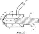
FIG. 2C is a cross-sectional view of the components ofFIG. 2a when assembled; -
FIG. 2D is an isometric view of the nozzle ofFIG. 2a ; -
FIG. 2E is an alternate view of the nozzle ofFIG. 2a ; and -
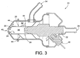
FIG. 3 is a cross-sectional view of an alternate embodiment of a nozzle in accordance with the teachings herein. - There are generally two primary categories of fuel nozzles - air assist nozzles and air blast nozzles. Air-assist and air-blast nozzles are only separated by the flow quantity of air. The nozzle described herein can be used with a wide range of airflows that allows it to operate in both categories. For example, the fuel nozzle operates in one embodiment in a diesel engine exhaust environment that uses diesel fuel for combustion with constraints of large turn down ratios of fuel flow greater than 15:1 and low fuel pressure. The resulting fuel droplets in such an environment can be less than 50 µm in size using the fuel nozzle.
- The fuel nozzle shall be described via operation as a pre-filming air-blast nozzle. During operation, fuel is metered onto a surface uniformly. High velocity air flows on both sides of the surface towards an atomizing edge of the surface, resulting in fuel being carried towards the atomizing edge of the surface by friction with flowing air or momentum of the fuel film. At the atomizing edge, the high velocity air on both sides of the surface meet, resulting in fuel droplets being "ripped" off the surface.
- Turning now to
FIGS. 1-3 , afuel injector 22 is used to provide fuel metering in thenozzle 20. In one embodiment, an automotive style PWM fuel injector is used. Thefuel injector 22 allows large turndown ratios of flow and is only used as a metering device to get the fuel onto thefilming surface 24 ofnozzle insert 26. The nozzle insert 26 fits onto theinjector 22, thereby changing thenozzle 20 to operate as a pre-filming air-assist/air-blast nozzle. - The nozzle operation is "detached" from injector droplet size. The injector needs only to wet the
inner surfaces 24 of nozzle insert 26 with fuel that enters the injector thoughpassage 28. The nozzle will work as long as the fuel spray impinges on theinner nozzle surfaces 24. Airflow pulls the fuel film along theinner chamber surface 24 towards thenozzle exit 30. Assist air enters theouter chamber 32 through atangential opening 34 and swirls around theinsert 26. Some of the assist air passes to thecenter chamber 36 of theinsert 26 throughtangential holes 38 ininsert 26 near the tip of theinjector 22. Air in thecenter chamber 36 swirls towards thenozzle exit 30 along the wetted fuel surface and takes the fuel film towards the atomizinglip 40. The remainder of the assist air stays in theouter chamber 32. In one embodiment, the air in theouter chamber 32 passes through swirlingpassages 42 that are cut in theinsert 26. In another embodiment,swirler fins 44 are used to swirl the air flow. In the embodiment shown inFIGS 2a-2e , theswirler fins 44 are formed inswirler plate 46. The outer chamber air flow maintains high velocity at theatomizing lip 40 and dictates flow patternization. The inner chamber air flow and outer chamber air flow join at the atomizing lip, resulting in the air flows shearing fuel droplets off of theatomizing lip 40. Initial droplet direction is also determined by the air flows. Thenozzle 20 has an opening for aninterface 48 that interfaces thefuel injector 22 with a controller (not shown). The controller may be a separate controller for the fuel nozzle, part of a system controller, etc. - Another aspect of the nozzle design is that the air provides thermal protection for the
injector 22 and the fuel-wettedinner surface 24. The inner surface must be kept below a safe temperature to prevent fuel coking. For example, with diesel fuel, a safe temperature would generally be below approximately 130 °C. The nozzle uses the injector as a metering device and improves the performance range over which small droplet atomization can be achieved. The air-assist/blast configuration creates very small droplets over a large fuel flow range when compared to using a conventional fuel injector. Note that the nozzle can be used with or without swirl and in a burner application or as a simple fuel doser system. Note that the ability of air-blast and air-assist nozzles to create very specific spray characteristics has led to the adaptation of these nozzles to many more applications than combustors. As such the nozzle described herein can be used for many applications that requires small droplet sizes across a wide liquid flow rate and has a source of atomizing gas. Some of these applications include paint sprayers, hydrocarbon dosers, Urea dosers, etc. - From the foregoing, it can be seen that the pre-filming fuel nozzle described is readily manufacturable. The housing generally consists of two
sections 48, 50, which allows thefuel injector 22 and nozzle insert 26 to be readily mounted within the housing.
Claims (9)
- A pre-filming fuel nozzle comprising
a fuel injector (22) having a fuel inlet passage (28) for providing fuel to the fuel injector (22), and
a housing havingan outer chamber (32), andan air passage (38) for air to enter the outer chamber (32) in the housing,a nozzle insert (26) havinga center chamber (36) with an inner surface (24), andan atomizing lip (40),wherein the outer chamber (32) is in air communication with the center chamber (36) through openings (38) in the nozzle insert (26);whereby the housing, the fuel injector and the nozzle insert are adapted so that during operation,fuel from the fuel injector (22) impinges on the inner surface (24) of the nozzle insert (26) and is pulled towards the atomizing lip (40) from air flow through the nozzle insert (26) that enters through the openings (38) from the outer chamber (32),the air flow through the nozzle insert (26) and air flow through the outer chamber (32) joining at the atomizing lip (40), resulting in air flows shearing fuel droplets off of the atomizing lip;wherein the nozzle insert (26) is adapted to fit over an output of the fuel injector (22) such that the openings (38) are arranged near the tip of the fuel injector (22). - The pre-filming fuel nozzle of claim 1 wherein the fuel injector is a pulse-width modulated fuel injector.
- The pre-filming nozzle of claim 1 further comprising swirler fins attached to the nozzle insert.
- The pre-filming nozzle of claim 1 wherein the nozzle insert has swirler passages.
- The pre-filming nozzle of claim 1 wherein the housing is a two-piece housing.
- The pre-filming nozzle of claim 1 wherein the air flow through the chamber has a higher velocity at the atomizing lip than the air flow through the nozzle insert.
- The pre-filming nozzle of claim 1 wherein the housing has an interface opening for an interface that interfaces the fuel injector to a controller.
- The pre-filming nozzle of claim 1 wherein the air flow through the chamber and the air flow through the nozzle insert provides thermal protection for the fuel injector.
- The pre-filming nozzle of claim 1 wherein the fuel injector is configured to operate as a fuel doser in a fuel doser system.
Applications Claiming Priority (2)
| Application Number | Priority Date | Filing Date | Title |
|---|---|---|---|
| US11/943,796 US8091805B2 (en) | 2007-11-21 | 2007-11-21 | Split-flow pre-filming fuel nozzle |
| PCT/US2008/083335 WO2009067376A2 (en) | 2007-11-21 | 2008-11-13 | Split-flow pre-filming fuel nozzle |
Publications (3)
| Publication Number | Publication Date |
|---|---|
| EP2223017A2 EP2223017A2 (en) | 2010-09-01 |
| EP2223017A4 EP2223017A4 (en) | 2014-01-22 |
| EP2223017B1 true EP2223017B1 (en) | 2019-01-09 |
Family
ID=40640633
Family Applications (1)
| Application Number | Title | Priority Date | Filing Date |
|---|---|---|---|
| EP08852806.2A Not-in-force EP2223017B1 (en) | 2007-11-21 | 2008-11-13 | Split-flow pre-filming fuel nozzle |
Country Status (5)
| Country | Link |
|---|---|
| US (1) | US8091805B2 (en) |
| EP (1) | EP2223017B1 (en) |
| JP (1) | JP2011504220A (en) |
| CN (1) | CN101932881B (en) |
| WO (1) | WO2009067376A2 (en) |
Families Citing this family (29)
| Publication number | Priority date | Publication date | Assignee | Title |
|---|---|---|---|---|
| US8277810B2 (en) | 2003-11-04 | 2012-10-02 | Novartis Vaccines & Diagnostics, Inc. | Antagonist anti-CD40 antibodies |
| US8091362B2 (en) * | 2008-08-20 | 2012-01-10 | Woodward, Inc. | Fuel injector sans support/stem |
| US8800895B2 (en) * | 2008-08-27 | 2014-08-12 | Woodward, Inc. | Piloted variable area fuel injector |
| US7827795B2 (en) * | 2008-09-19 | 2010-11-09 | Woodward Governor Company | Active thermal protection for fuel injectors |
| US7832377B2 (en) * | 2008-09-19 | 2010-11-16 | Woodward Governor Company | Thermal protection for fuel injectors |
| US20110073071A1 (en) * | 2009-09-30 | 2011-03-31 | Woodward Governor Company | Internally Nested Variable-Area Fuel Nozzle |
| US9683739B2 (en) * | 2009-11-09 | 2017-06-20 | Woodward, Inc. | Variable-area fuel injector with improved circumferential spray uniformity |
| US20120138710A1 (en) * | 2010-12-01 | 2012-06-07 | Pratt & Whitney Rocketdyne Inc. | Hybrid Variable Area Fuel Injector With Thermal Protection |
| US8365534B2 (en) | 2011-03-15 | 2013-02-05 | General Electric Company | Gas turbine combustor having a fuel nozzle for flame anchoring |
| RU2011115528A (en) | 2011-04-21 | 2012-10-27 | Дженерал Электрик Компани (US) | FUEL INJECTOR, COMBUSTION CHAMBER AND METHOD OF OPERATION OF THE COMBUSTION CHAMBER |
| CN103028217A (en) * | 2011-09-29 | 2013-04-10 | 上海磊诺工业气体有限公司 | Flush type gas nozzle |
| WO2015174880A1 (en) | 2014-05-12 | 2015-11-19 | General Electric Company | Pre-film liquid fuel cartridge |
| GB201411747D0 (en) * | 2014-07-01 | 2014-08-13 | Spectus Energy Ltd | Improvements to hydraulic tip fluid injection valve |
| JP6417620B2 (en) * | 2014-10-24 | 2018-11-07 | 三菱日立パワーシステムズ株式会社 | Combustor, gas turbine |
| CN104948276A (en) * | 2015-05-13 | 2015-09-30 | 中国重汽集团济南动力有限公司 | Air assisting type urea ejector |
| CN104948273A (en) * | 2015-05-13 | 2015-09-30 | 中国重汽集团济南动力有限公司 | Air assisting type urea injection system |
| US9927126B2 (en) * | 2015-06-10 | 2018-03-27 | General Electric Company | Prefilming air blast (PAB) pilot for low emissions combustors |
| US10267524B2 (en) * | 2015-09-16 | 2019-04-23 | Woodward, Inc. | Prefilming fuel/air mixer |
| US9845780B2 (en) | 2015-11-04 | 2017-12-19 | Ford Global Technologies, Llc | Annulus nozzle injector with tangential fins |
| US9840994B2 (en) | 2015-11-04 | 2017-12-12 | Ford Global Technologies, Llc | Annulus nozzle injector with tangential fins |
| CN106216123A (en) * | 2016-09-22 | 2016-12-14 | 广东圣米亚经济发展有限公司 | Airbrush and the attachment structure of shower nozzle fast assembling-disassembling |
| CN107044636B (en) * | 2017-04-27 | 2018-11-06 | 中国科学院工程热物理研究所 | A kind of vaporizer tube combustor fuel injection equipment (FIE) |
| JP6954109B2 (en) | 2017-12-27 | 2021-10-27 | いすゞ自動車株式会社 | Urea water injection device |
| US10865714B2 (en) | 2018-03-22 | 2020-12-15 | Woodward. Inc. | Gas turbine engine fuel injector |
| US11149950B2 (en) | 2018-06-11 | 2021-10-19 | Woodward, Inc. | Pre-swirl pressure atomizing tip |
| CN113669161A (en) * | 2021-08-24 | 2021-11-19 | 中国航发贵阳发动机设计研究所 | An igniter with oxygen supplement structure |
| DE102022002113A1 (en) * | 2022-06-13 | 2023-12-14 | Mercedes-Benz Group AG | Burner for a motor vehicle, method for operating such a burner and motor vehicle |
| DE102022002111A1 (en) | 2022-06-13 | 2023-12-14 | Mercedes-Benz Group AG | Burner for a motor vehicle and motor vehicle with at least one such burner |
| US12092331B2 (en) | 2022-11-23 | 2024-09-17 | Woodward, Inc. | Tangential pressure atomizing tip without feed chamber |
Family Cites Families (14)
| Publication number | Priority date | Publication date | Assignee | Title |
|---|---|---|---|---|
| US3866413A (en) * | 1973-01-22 | 1975-02-18 | Parker Hannifin Corp | Air blast fuel atomizer |
| US4595143A (en) * | 1983-07-20 | 1986-06-17 | Parker-Hannifin Corporation | Air swirl nozzle |
| DE3642122C1 (en) | 1986-12-10 | 1988-06-09 | Mtu Muenchen Gmbh | Fuel injector |
| JPH02275207A (en) | 1989-04-14 | 1990-11-09 | Nissan Motor Co Ltd | Fuel injection nozzle |
| DE4127455A1 (en) | 1991-08-20 | 1993-02-25 | Uwegas Gmbh | Electromagnetically controlled fuel injector with integrated ignition device - pumps fuel into cylinder by pressure wave from sliding disc impelled against opposition of restoring spring |
| JPH0849513A (en) | 1994-08-04 | 1996-02-20 | Mitsubishi Motors Corp | Wave spring type valve spring device |
| JPH08261464A (en) | 1995-03-20 | 1996-10-11 | Ishikawajima Harima Heavy Ind Co Ltd | Turbulent mixed fuel injection valve |
| JP2000304210A (en) * | 1999-02-19 | 2000-11-02 | Denso Corp | Combustion equipment |
| US6174160B1 (en) * | 1999-03-25 | 2001-01-16 | University Of Washington | Staged prevaporizer-premixer |
| US6547163B1 (en) * | 1999-10-01 | 2003-04-15 | Parker-Hannifin Corporation | Hybrid atomizing fuel nozzle |
| US6688534B2 (en) * | 2001-03-07 | 2004-02-10 | Delavan Inc | Air assist fuel nozzle |
| DE10327697A1 (en) * | 2003-06-20 | 2005-01-05 | Robert Bosch Gmbh | Burner for liquid fuels |
| DE102005022772A1 (en) * | 2005-05-12 | 2007-01-11 | Universität Karlsruhe | Burner with partial premixing and pre-evaporation of the liquid fuel |
| JP4728176B2 (en) | 2005-06-24 | 2011-07-20 | 株式会社日立製作所 | Burner, gas turbine combustor and burner cooling method |
-
2007
- 2007-11-21 US US11/943,796 patent/US8091805B2/en not_active Expired - Fee Related
-
2008
- 2008-11-13 EP EP08852806.2A patent/EP2223017B1/en not_active Not-in-force
- 2008-11-13 WO PCT/US2008/083335 patent/WO2009067376A2/en not_active Ceased
- 2008-11-13 JP JP2010535005A patent/JP2011504220A/en active Pending
- 2008-11-13 CN CN2008801169518A patent/CN101932881B/en not_active Expired - Fee Related
Non-Patent Citations (1)
| Title |
|---|
| None * |
Also Published As
| Publication number | Publication date |
|---|---|
| WO2009067376A2 (en) | 2009-05-28 |
| US8091805B2 (en) | 2012-01-10 |
| EP2223017A2 (en) | 2010-09-01 |
| CN101932881B (en) | 2012-06-27 |
| EP2223017A4 (en) | 2014-01-22 |
| CN101932881A (en) | 2010-12-29 |
| US20090126687A1 (en) | 2009-05-21 |
| WO2009067376A3 (en) | 2009-09-03 |
| JP2011504220A (en) | 2011-02-03 |
Similar Documents
| Publication | Publication Date | Title |
|---|---|---|
| US8091805B2 (en) | Split-flow pre-filming fuel nozzle | |
| US7926744B2 (en) | Radially outward flowing air-blast fuel injector for gas turbine engine | |
| CN101029739B (en) | Combustion chamber of gas turbine engine and the gas turbine engine | |
| US3866413A (en) | Air blast fuel atomizer | |
| RU2382942C2 (en) | Foaming atomiser for aero-mechanical injection system of air-and-fuel mixture to combustion chamber of turbomachine, aero-and-fuel injection system, combustion chamber of turbomachine, and turbomachine | |
| RU2348829C2 (en) | System for liquid fuel supply and device for processing and supply of liquid fuel | |
| US6198038B1 (en) | Burner and burner/emitter/recuperator assembly for direct energy conversion power sources | |
| US20090255258A1 (en) | Pre-filming air-blast fuel injector having a reduced hydraulic spray angle | |
| US9771903B2 (en) | Multi-physics fuel atomizer and methods | |
| CN109945235B (en) | Fuel nozzle, combustion chamber and aircraft engine | |
| JP2002327921A (en) | Fuel injection device, fuel nozzle and fuel spray method | |
| JPH09509733A (en) | Fuel nozzle introduced from the tangential direction | |
| US9970356B2 (en) | Atomizer, combustion device including atomizer, and gas turbine plant | |
| JP2002195563A (en) | Method and apparatus for reducing combustor emissions | |
| GB2458022A (en) | Air-Blast Fuel Injection Nozzle With Diverging Exit Region | |
| JPH11304111A (en) | How to operate a premix burner | |
| JP6491898B2 (en) | Spray nozzle, combustion apparatus using spray nozzle, and gas turbine plant | |
| JP5610446B2 (en) | Gas turbine combustor | |
| US20090061365A1 (en) | Burner for fluid fuels and method for operating such a burner | |
| US4850195A (en) | Fuel spray combustion device | |
| CN109945233A (en) | Combustion chamber and its atomising device, aero gas turbine engine | |
| JP2002038970A (en) | Gas turbine combustor | |
| CA2154452A1 (en) | Dual fuel injection nozzle with water injection | |
| WO2022250549A1 (en) | A unidirectional fuel nozzle for improving fuel atomization in a carburetor or similar apparatus | |
| JP2013531219A (en) | Fuel combustion burner for vehicle exhaust components |
Legal Events
| Date | Code | Title | Description |
|---|---|---|---|
| PUAI | Public reference made under article 153(3) epc to a published international application that has entered the european phase |
Free format text: ORIGINAL CODE: 0009012 |
|
| 17P | Request for examination filed |
Effective date: 20100607 |
|
| AK | Designated contracting states |
Kind code of ref document: A2 Designated state(s): AT BE BG CH CY CZ DE DK EE ES FI FR GB GR HR HU IE IS IT LI LT LU LV MC MT NL NO PL PT RO SE SI SK TR |
|
| AX | Request for extension of the european patent |
Extension state: AL BA MK RS |
|
| DAX | Request for extension of the european patent (deleted) | ||
| RAP1 | Party data changed (applicant data changed or rights of an application transferred) |
Owner name: WOODWARD, INC. |
|
| A4 | Supplementary search report drawn up and despatched |
Effective date: 20140103 |
|
| RIC1 | Information provided on ipc code assigned before grant |
Ipc: F23D 14/24 20060101ALI20131218BHEP Ipc: F23D 11/10 20060101ALI20131218BHEP Ipc: F23D 14/46 20060101ALI20131218BHEP Ipc: F23R 3/28 20060101AFI20131218BHEP Ipc: F23D 11/38 20060101ALI20131218BHEP Ipc: F01N 3/025 20060101ALI20131218BHEP |
|
| RAP1 | Party data changed (applicant data changed or rights of an application transferred) |
Owner name: WOODWARD, INC. |
|
| GRAP | Despatch of communication of intention to grant a patent |
Free format text: ORIGINAL CODE: EPIDOSNIGR1 |
|
| STAA | Information on the status of an ep patent application or granted ep patent |
Free format text: STATUS: GRANT OF PATENT IS INTENDED |
|
| RIC1 | Information provided on ipc code assigned before grant |
Ipc: F23D 14/46 20060101ALI20180523BHEP Ipc: F23D 11/38 20060101ALI20180523BHEP Ipc: F23D 11/10 20060101ALI20180523BHEP Ipc: F23R 3/28 20060101AFI20180523BHEP Ipc: F01N 3/025 20060101ALI20180523BHEP Ipc: F23D 14/24 20060101ALI20180523BHEP |
|
| INTG | Intention to grant announced |
Effective date: 20180620 |
|
| GRAS | Grant fee paid |
Free format text: ORIGINAL CODE: EPIDOSNIGR3 |
|
| GRAA | (expected) grant |
Free format text: ORIGINAL CODE: 0009210 |
|
| STAA | Information on the status of an ep patent application or granted ep patent |
Free format text: STATUS: THE PATENT HAS BEEN GRANTED |
|
| AK | Designated contracting states |
Kind code of ref document: B1 Designated state(s): AT BE BG CH CY CZ DE DK EE ES FI FR GB GR HR HU IE IS IT LI LT LU LV MC MT NL NO PL PT RO SE SI SK TR |
|
| REG | Reference to a national code |
Ref country code: GB Ref legal event code: FG4D |
|
| REG | Reference to a national code |
Ref country code: CH Ref legal event code: EP Ref country code: AT Ref legal event code: REF Ref document number: 1087781 Country of ref document: AT Kind code of ref document: T Effective date: 20190115 |
|
| REG | Reference to a national code |
Ref country code: DE Ref legal event code: R096 Ref document number: 602008058717 Country of ref document: DE |
|
| REG | Reference to a national code |
Ref country code: IE Ref legal event code: FG4D |
|
| REG | Reference to a national code |
Ref country code: NL Ref legal event code: MP Effective date: 20190109 |
|
| REG | Reference to a national code |
Ref country code: LT Ref legal event code: MG4D |
|
| PG25 | Lapsed in a contracting state [announced via postgrant information from national office to epo] |
Ref country code: NL Free format text: LAPSE BECAUSE OF FAILURE TO SUBMIT A TRANSLATION OF THE DESCRIPTION OR TO PAY THE FEE WITHIN THE PRESCRIBED TIME-LIMIT Effective date: 20190109 |
|
| REG | Reference to a national code |
Ref country code: AT Ref legal event code: MK05 Ref document number: 1087781 Country of ref document: AT Kind code of ref document: T Effective date: 20190109 |
|
| PG25 | Lapsed in a contracting state [announced via postgrant information from national office to epo] |
Ref country code: PL Free format text: LAPSE BECAUSE OF FAILURE TO SUBMIT A TRANSLATION OF THE DESCRIPTION OR TO PAY THE FEE WITHIN THE PRESCRIBED TIME-LIMIT Effective date: 20190109 Ref country code: LT Free format text: LAPSE BECAUSE OF FAILURE TO SUBMIT A TRANSLATION OF THE DESCRIPTION OR TO PAY THE FEE WITHIN THE PRESCRIBED TIME-LIMIT Effective date: 20190109 Ref country code: ES Free format text: LAPSE BECAUSE OF FAILURE TO SUBMIT A TRANSLATION OF THE DESCRIPTION OR TO PAY THE FEE WITHIN THE PRESCRIBED TIME-LIMIT Effective date: 20190109 Ref country code: NO Free format text: LAPSE BECAUSE OF FAILURE TO SUBMIT A TRANSLATION OF THE DESCRIPTION OR TO PAY THE FEE WITHIN THE PRESCRIBED TIME-LIMIT Effective date: 20190409 Ref country code: PT Free format text: LAPSE BECAUSE OF FAILURE TO SUBMIT A TRANSLATION OF THE DESCRIPTION OR TO PAY THE FEE WITHIN THE PRESCRIBED TIME-LIMIT Effective date: 20190509 Ref country code: FI Free format text: LAPSE BECAUSE OF FAILURE TO SUBMIT A TRANSLATION OF THE DESCRIPTION OR TO PAY THE FEE WITHIN THE PRESCRIBED TIME-LIMIT Effective date: 20190109 Ref country code: SE Free format text: LAPSE BECAUSE OF FAILURE TO SUBMIT A TRANSLATION OF THE DESCRIPTION OR TO PAY THE FEE WITHIN THE PRESCRIBED TIME-LIMIT Effective date: 20190109 |
|
| PG25 | Lapsed in a contracting state [announced via postgrant information from national office to epo] |
Ref country code: GR Free format text: LAPSE BECAUSE OF FAILURE TO SUBMIT A TRANSLATION OF THE DESCRIPTION OR TO PAY THE FEE WITHIN THE PRESCRIBED TIME-LIMIT Effective date: 20190410 Ref country code: IS Free format text: LAPSE BECAUSE OF FAILURE TO SUBMIT A TRANSLATION OF THE DESCRIPTION OR TO PAY THE FEE WITHIN THE PRESCRIBED TIME-LIMIT Effective date: 20190509 Ref country code: LV Free format text: LAPSE BECAUSE OF FAILURE TO SUBMIT A TRANSLATION OF THE DESCRIPTION OR TO PAY THE FEE WITHIN THE PRESCRIBED TIME-LIMIT Effective date: 20190109 Ref country code: HR Free format text: LAPSE BECAUSE OF FAILURE TO SUBMIT A TRANSLATION OF THE DESCRIPTION OR TO PAY THE FEE WITHIN THE PRESCRIBED TIME-LIMIT Effective date: 20190109 Ref country code: BG Free format text: LAPSE BECAUSE OF FAILURE TO SUBMIT A TRANSLATION OF THE DESCRIPTION OR TO PAY THE FEE WITHIN THE PRESCRIBED TIME-LIMIT Effective date: 20190409 |
|
| REG | Reference to a national code |
Ref country code: DE Ref legal event code: R097 Ref document number: 602008058717 Country of ref document: DE |
|
| PG25 | Lapsed in a contracting state [announced via postgrant information from national office to epo] |
Ref country code: CZ Free format text: LAPSE BECAUSE OF FAILURE TO SUBMIT A TRANSLATION OF THE DESCRIPTION OR TO PAY THE FEE WITHIN THE PRESCRIBED TIME-LIMIT Effective date: 20190109 Ref country code: RO Free format text: LAPSE BECAUSE OF FAILURE TO SUBMIT A TRANSLATION OF THE DESCRIPTION OR TO PAY THE FEE WITHIN THE PRESCRIBED TIME-LIMIT Effective date: 20190109 Ref country code: EE Free format text: LAPSE BECAUSE OF FAILURE TO SUBMIT A TRANSLATION OF THE DESCRIPTION OR TO PAY THE FEE WITHIN THE PRESCRIBED TIME-LIMIT Effective date: 20190109 Ref country code: SK Free format text: LAPSE BECAUSE OF FAILURE TO SUBMIT A TRANSLATION OF THE DESCRIPTION OR TO PAY THE FEE WITHIN THE PRESCRIBED TIME-LIMIT Effective date: 20190109 Ref country code: AT Free format text: LAPSE BECAUSE OF FAILURE TO SUBMIT A TRANSLATION OF THE DESCRIPTION OR TO PAY THE FEE WITHIN THE PRESCRIBED TIME-LIMIT Effective date: 20190109 Ref country code: DK Free format text: LAPSE BECAUSE OF FAILURE TO SUBMIT A TRANSLATION OF THE DESCRIPTION OR TO PAY THE FEE WITHIN THE PRESCRIBED TIME-LIMIT Effective date: 20190109 Ref country code: IT Free format text: LAPSE BECAUSE OF FAILURE TO SUBMIT A TRANSLATION OF THE DESCRIPTION OR TO PAY THE FEE WITHIN THE PRESCRIBED TIME-LIMIT Effective date: 20190109 |
|
| PLBE | No opposition filed within time limit |
Free format text: ORIGINAL CODE: 0009261 |
|
| STAA | Information on the status of an ep patent application or granted ep patent |
Free format text: STATUS: NO OPPOSITION FILED WITHIN TIME LIMIT |
|
| 26N | No opposition filed |
Effective date: 20191010 |
|
| PG25 | Lapsed in a contracting state [announced via postgrant information from national office to epo] |
Ref country code: SI Free format text: LAPSE BECAUSE OF FAILURE TO SUBMIT A TRANSLATION OF THE DESCRIPTION OR TO PAY THE FEE WITHIN THE PRESCRIBED TIME-LIMIT Effective date: 20190109 |
|
| PG25 | Lapsed in a contracting state [announced via postgrant information from national office to epo] |
Ref country code: TR Free format text: LAPSE BECAUSE OF FAILURE TO SUBMIT A TRANSLATION OF THE DESCRIPTION OR TO PAY THE FEE WITHIN THE PRESCRIBED TIME-LIMIT Effective date: 20190109 |
|
| REG | Reference to a national code |
Ref country code: CH Ref legal event code: PL |
|
| PG25 | Lapsed in a contracting state [announced via postgrant information from national office to epo] |
Ref country code: LU Free format text: LAPSE BECAUSE OF NON-PAYMENT OF DUE FEES Effective date: 20191113 Ref country code: LI Free format text: LAPSE BECAUSE OF NON-PAYMENT OF DUE FEES Effective date: 20191130 Ref country code: MC Free format text: LAPSE BECAUSE OF FAILURE TO SUBMIT A TRANSLATION OF THE DESCRIPTION OR TO PAY THE FEE WITHIN THE PRESCRIBED TIME-LIMIT Effective date: 20190109 Ref country code: CH Free format text: LAPSE BECAUSE OF NON-PAYMENT OF DUE FEES Effective date: 20191130 |
|
| REG | Reference to a national code |
Ref country code: BE Ref legal event code: MM Effective date: 20191130 |
|
| PG25 | Lapsed in a contracting state [announced via postgrant information from national office to epo] |
Ref country code: IE Free format text: LAPSE BECAUSE OF NON-PAYMENT OF DUE FEES Effective date: 20191113 Ref country code: FR Free format text: LAPSE BECAUSE OF NON-PAYMENT OF DUE FEES Effective date: 20191130 |
|
| PG25 | Lapsed in a contracting state [announced via postgrant information from national office to epo] |
Ref country code: BE Free format text: LAPSE BECAUSE OF NON-PAYMENT OF DUE FEES Effective date: 20191130 |
|
| PG25 | Lapsed in a contracting state [announced via postgrant information from national office to epo] |
Ref country code: CY Free format text: LAPSE BECAUSE OF FAILURE TO SUBMIT A TRANSLATION OF THE DESCRIPTION OR TO PAY THE FEE WITHIN THE PRESCRIBED TIME-LIMIT Effective date: 20190109 |
|
| PG25 | Lapsed in a contracting state [announced via postgrant information from national office to epo] |
Ref country code: MT Free format text: LAPSE BECAUSE OF FAILURE TO SUBMIT A TRANSLATION OF THE DESCRIPTION OR TO PAY THE FEE WITHIN THE PRESCRIBED TIME-LIMIT Effective date: 20190109 Ref country code: HU Free format text: LAPSE BECAUSE OF FAILURE TO SUBMIT A TRANSLATION OF THE DESCRIPTION OR TO PAY THE FEE WITHIN THE PRESCRIBED TIME-LIMIT; INVALID AB INITIO Effective date: 20081113 |
|
| PGFP | Annual fee paid to national office [announced via postgrant information from national office to epo] |
Ref country code: GB Payment date: 20221128 Year of fee payment: 15 Ref country code: DE Payment date: 20221125 Year of fee payment: 15 |
|
| REG | Reference to a national code |
Ref country code: DE Ref legal event code: R119 Ref document number: 602008058717 Country of ref document: DE |
|
| GBPC | Gb: european patent ceased through non-payment of renewal fee |
Effective date: 20231113 |
|
| PG25 | Lapsed in a contracting state [announced via postgrant information from national office to epo] |
Ref country code: DE Free format text: LAPSE BECAUSE OF NON-PAYMENT OF DUE FEES Effective date: 20240601 |
|
| PG25 | Lapsed in a contracting state [announced via postgrant information from national office to epo] |
Ref country code: GB Free format text: LAPSE BECAUSE OF NON-PAYMENT OF DUE FEES Effective date: 20231113 |
|
| PG25 | Lapsed in a contracting state [announced via postgrant information from national office to epo] |
Ref country code: GB Free format text: LAPSE BECAUSE OF NON-PAYMENT OF DUE FEES Effective date: 20231113 Ref country code: DE Free format text: LAPSE BECAUSE OF NON-PAYMENT OF DUE FEES Effective date: 20240601 |