EP2222035B1 - Power saving method and device - Google Patents
Power saving method and device Download PDFInfo
- Publication number
- EP2222035B1 EP2222035B1 EP20080856806 EP08856806A EP2222035B1 EP 2222035 B1 EP2222035 B1 EP 2222035B1 EP 20080856806 EP20080856806 EP 20080856806 EP 08856806 A EP08856806 A EP 08856806A EP 2222035 B1 EP2222035 B1 EP 2222035B1
- Authority
- EP
- European Patent Office
- Prior art keywords
- status
- communication
- section
- energy
- threshold value
- Prior art date
- Legal status (The legal status is an assumption and is not a legal conclusion. Google has not performed a legal analysis and makes no representation as to the accuracy of the status listed.)
- Not-in-force
Links
Images



Classifications
-
- H—ELECTRICITY
- H04—ELECTRIC COMMUNICATION TECHNIQUE
- H04L—TRANSMISSION OF DIGITAL INFORMATION, e.g. TELEGRAPHIC COMMUNICATION
- H04L12/00—Data switching networks
- H04L12/28—Data switching networks characterised by path configuration, e.g. LAN [Local Area Networks] or WAN [Wide Area Networks]
- H04L12/44—Star or tree networks
-
- G—PHYSICS
- G06—COMPUTING OR CALCULATING; COUNTING
- G06F—ELECTRIC DIGITAL DATA PROCESSING
- G06F1/00—Details not covered by groups G06F3/00 - G06F13/00 and G06F21/00
- G06F1/26—Power supply means, e.g. regulation thereof
- G06F1/32—Means for saving power
- G06F1/3203—Power management, i.e. event-based initiation of a power-saving mode
-
- H—ELECTRICITY
- H04—ELECTRIC COMMUNICATION TECHNIQUE
- H04L—TRANSMISSION OF DIGITAL INFORMATION, e.g. TELEGRAPHIC COMMUNICATION
- H04L12/00—Data switching networks
- H04L12/02—Details
- H04L12/12—Arrangements for remote connection or disconnection of substations or of equipment thereof
-
- Y—GENERAL TAGGING OF NEW TECHNOLOGICAL DEVELOPMENTS; GENERAL TAGGING OF CROSS-SECTIONAL TECHNOLOGIES SPANNING OVER SEVERAL SECTIONS OF THE IPC; TECHNICAL SUBJECTS COVERED BY FORMER USPC CROSS-REFERENCE ART COLLECTIONS [XRACs] AND DIGESTS
- Y02—TECHNOLOGIES OR APPLICATIONS FOR MITIGATION OR ADAPTATION AGAINST CLIMATE CHANGE
- Y02D—CLIMATE CHANGE MITIGATION TECHNOLOGIES IN INFORMATION AND COMMUNICATION TECHNOLOGIES [ICT], I.E. INFORMATION AND COMMUNICATION TECHNOLOGIES AIMING AT THE REDUCTION OF THEIR OWN ENERGY USE
- Y02D30/00—Reducing energy consumption in communication networks
- Y02D30/50—Reducing energy consumption in communication networks in wire-line communication networks, e.g. low power modes or reduced link rate
Definitions
- This invention relates to a power-saving technique in communication devices such as switching hubs and routers.
- Communication devices such as switching hubs and routers often comprise a status indicator (e.g., LED) for indicating the operational status of the device itself.
- a status indicator e.g., LED
- Such status indicators are recognized visually as the operational status of the communication device by the user (e.g., network administrator). However, in general, it is rare that the user constantly monitors the operational status of the communication device. If the status indicator of the communication device operates while the user is not particularly performing monitoring of the status, power is consumed, and it is undesirable in view of power-saving (energy-saving).
- Prior art to this application includes, for example. JP2000-051764 A (patent document 1), JP2003-037545 A (patent document 2) and JP2002-347200 A (patent document 3), which disclose the technique relating to power-saving in, for example, mobile phones or mobile communication terminals.
- JP2000-051764 A (patent document 1)
- JP2003-037545 A (patent document 2)
- JP2002-347200 A patent document 3
- US 2006/0038506 discloses systems and methods that may be employed for receiving a power consumption signal.
- US 2003/0191854 discloses a method and an apparatus for reducing power consumption in a network linking system.
- An object of this invention is to provide a communication device capable of power-saving (energy-saving) and a control technique thereof.
- the light of the status indicator of the status indicating section is turned off or is set to a relatively low luminance, such that a power-saving of a communication device is possible.
- Fig. 1 is a block diagram of a communication device 1.
- the communication device 1 includes a status indicating section 12 and an energy-saving mode indicating LED 14, as well as a Switch/PHY circuit (Switch/PHY IC) 18, LED driving section 20, Switch/PHY monitoring section 22, energy-saving control section 24, setting storage section 25 and PUSH switch 26.
- the Switch/PHY circuit 18 and LED driving section 20 are often integrally-constituted.
- the energy-saving control section 24 performs control relating to an energy-saving mode as will be described later, and is built into the Switch/PHY monitoring section 22 in this embodiment.
- the setting storage section 25 is also built into the Switch/PHY monitoring section 22.
- the Switch/PHY monitoring section 22 monitors the status of the Switch/PHY circuit 18 based on the data indicating the current link status or communication volume of the communication port 10, which is passed from the Switch/PHY circuit 18.
- the push switch 26 is used for setting the energy-saving mode to be active or not.
- each LED of the status indicating section 12 corresponds to a "status indicator”
- the Switch/PHY circuit 18 and Switch/PHY monitoring section 22 correspond to a “communication monitoring section”
- the LED driving section 20 corresponds to a “status indicator driving section”
- the energy-saving control section 24 corresponds to a "lighting control section.”
- Fig. 2 is a status transition diagram relating to an energy-saving mode in a communication device 1.
- the "energy-saving mode” refers to forcibly turning off the light of the status indicating section 12 when a certain condition (activation event) occurs. This energy saving mode is released when another condition (release event) occurs. Namely, the communication device 1 transitions the status from a "normal operation” to an "energy-saving mode activation standby" when the energy-saving mode is active. Then, the communication device 1 is turned to a status of waiting for a predetermined "activation event" (described later), and with the occurrence of the "activation event," the status transitions to an "energy-saving mode activation" status.
- the light of the status indicating section 12 is forcibly turned off, and the communication device 1 is turned to a status of waiting for a predetermined release event (described later).
- the communication device 1 transitions to an "energy-saving mode activation standby" status, and the status indicating section 12 is turned to a normal lighting status.
- the energy-saving mode is changed to be inactive, the status is transitioned from the "energy-saving mode activation” status to a "normal operation” status, and the status indicating section 12 is turned to a normal lighting status.
- the switching of the energy-saving mode can be performed using a Push switch 26.
- the on/off setting of the energy-saving mode is stored in a setting storage section 25.
- Fig. 3 is a flow chart showing an operational procedure of an energy-saving control in a communication device 1. The energy-saving control will be described below along with the flowchart.
- the energy-saving control section 24 determines whether or not the energy-saving mode is currently active (step S10). Specifically, for example, the energy-saving control section 24 has a flag indicating an energy-saving mode when the energy-saving mode is active, and the above determination is made based on this flag. When the energy-saving mode is inactive (step S10; NO), the energy-saving control section 24 returns to the determination process of step S10 (return).
- the energy-saving control section 24 obtains the current status from the Switch/PHY circuit 18 (step S11). Specifically, the energy-saving control section 24 obtains information relating to the communication volume from the Switch/PHY circuit 18, and based on this, the current communication rate is calculated. For example, the current communication volume is determined as "xx Mbps,” and this communication volume is calculated for the percentage with respect to the allowable maximum communication volume (e.g., 100Mbps) in the communication device 1. For example, when the current communication volume is 40Mbps and the allowable maximum communication volume is 100Mbps, the communication rate is 40%.
- the setting of this communication volume is pre-set by, for example, a firmware implemented in the communication device 1 and stored in the setting storage section 25.
- the energy-saving control section 24 determines whether or not the status at that point is an "energy-saving mode activation standby" status (step S12). If the status is in an "energy-saving mode activation standby" status (step S12; YES), the energy-saving control section 24 determines whether or not to activate the energy-saving mode (step S13). Specifically, when the communication rate calculated in step S11 is lower than the pre-set activation threshold value (first threshold value), the energy-saving control section 24 performs a determination with respect to activating the energy-saving mode.
- the "activation threshold value” refers to a reference value for activating the energy-saving mode when the communication rate decreases, and this is a value that is set appropriately.
- This activation threshold value may be set to a value of about 40%. When the communication rate falls below the activation threshold value, this causes an "activation event occurrence" (see Fig. 2 ). Moreover, a determination of an "activation event occurrence" may be made after a lapse of a predetermined time from the point when the communication rate falls below the activation threshold value. Specific examples will be described later.
- the energy-saving control section 24 When the energy-saving mode is to be activated (step S13; YES), the energy-saving control section 24 outputs a control signal for turning off the light of each LED of the status indicating section 12 to the LED driving section 20 (step S14). Namely, the energy-saving control section 24 activates the energy-saving mode.
- a control for turning off the light of each LED of the status indicating section 12 will be described later.
- step S13; NO the energy-saving control section 24 returns to the determination process of step S10 (return).
- step S12 when the status at that point is an "energy-saving mode in operation" status (step S12; NO), the energy-saving control section 24 determines whether or not it is necessary to release the energy-saving mode (step S15). Specifically, when the communication rate calculated in step S11 is higher than the pre-set release threshold value (second threshold value), the energy-saving control section 24 performs a determination with respect to releasing the energy-saving mode.
- the "release threshold value” refers to a reference value for releasing the energy-saving mode when the communication rate increases, which is a value that is set appropriately. This release threshold value, for example, may be set to a value of about 50-60%. When the communication rate exceeds the release threshold value, this causes a "release event occurrence" (see Fig. 2 ).
- the energy-saving control section 24 may detect the change in link status (link-up/link-down) based on the current status obtained from the Switch/PHY circuit 18, and when a change in a link status occurs, a determination of a "release event occurrence" may be made.
- Each value of the above-mentioned activation threshold value and release threshold value may be set appropriately. For example, both values may be the same. More preferably, the release threshold value is larger than the activation threshold value. Therefore, even when the communication rate rises and falls at a value close to the activation threshold value, the release event does not occur as long as the communication rate does not go beyond the release threshold value. Thus, a frequent repetition of activation/release of the energy-saving mode can be avoided.
- the energy-saving control section 24 When the energy-saving mode is to be released (step S15; YES), the energy-saving control section 24 outputs the control signal for turning off the light of each LED of the status indicating section 12 to the LED driving section 20 (step S14). Namely, the energy-saving control section 24 releases the energy-saving mode.
- the energy-saving control section 24 releases the energy-saving mode.
- step S15 When a release of the energy-saving mode is not required (step S15; NO), the energy-saving control section 24 returns to the determination process of step S10 (return).
- the Switch/PHY circuit 18 when the Switch/PHY circuit 18 is holding the communication volume in a communication in a format such as by the number of bytes, this number of bytes, etc. may be obtained as the current status. In that case, when a predetermined number of bytes per unit time (e.g., for 1 sec.) is received, the status may be configured to be changed. Specifically, the activation threshold value (first threshold value) and release threshold value (second threshold value) are set, respectively, by, e.g., the number of bytes.
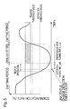
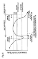
- each diagram the vertical axis corresponds to the communication rate (%) and the horizontal axis corresponds to time (t).
- Each diagram shows an example of a shift in the communication rate and a transition status of activation/release of the energy-saving mode corresponding thereto.
- a forcible turn-off period may be entered immediately at the point when the communication rate falls below the activation threshold value, but as shown in the drawing, the forcible turn-off period may also be entered after a lapse of a predetermined waiting time t_wait (hereinafter referred to as the "activation waiting time").
- the energy-saving control section 24 starts the timer at the point when the communication rate falls below the activation threshold value (corresponding to "timer in operation" in the drawing), and after the timer reaches the above-mentioned activation waiting time, a control for turning off the light of each LED of the status indicating section 12 is performed.
- the energy-saving control section 24 releases the forcible light-off period at the point when the communication rate exceeds the release threshold value such that the light of each LED of the status indicating section 12 is turned on as normal (emitting period). In the beginning, the light of each LED of the status indicating section 12 is turned on as normal (emitting period).
- the energy-saving mode is activated as described above, and the light of each LED of the status indicating section 12 is forcibly turned off (forcible light-off period).
- the energy-saving control section 24 activates the timer to measure the activation waiting time. However, if a change in link status is detected before a lapse of the activation waiting time t_wait, using this as a trigger, the energy-saving control section 24 resets the timer to 0 (reset of timer). After the timer reset, since the communication rate is still below the activation threshold value at that point, the energy-saving control section 24 activates the timer again.
- the energy-saving control section 24 performs a control for turning off the light of each LED of the status indicating section 12. Then, the energy-saving control section 24 releases the forcible turn-off period at the point when the communication rate exceeds the release threshold value such that the light of each LED of the status indicating section 12 is turned on as normal.
- the energy-saving control section 24 activates the timer to measure the activation waiting time.
- the energy-saving control section 24 resets the timer to 0 (reset of timer). Therefore, the light of each LED of the status indicating section 12 continues to be turned on. After the timer reset, since the communication rate exceeds the activation threshold value for a while, the energy-saving control section 24 does not perform an energy-saving control.
- the energy-saving control section 24 activates the timer to measure the activation waiting time. Since the communication rate was still low even after a lapse of a predetermined activation waiting time t_wait , similar to the above-mentioned example in Fig. 4 , the energy-saving control section 24 performs a control for turning off the light of each LED of the status indicating section 12.
- a driver chip 20b and on/off pin 20c correspond to the above-mentioned "LED driving section 20."
- a switching chip (SW) 18a outputs turn-on data for turning on the light of each LED of the status indicating section 12 by serial data.
- the driver chip 20b converts the serial data outputted from the switching chip 18a to parallel data, and further performs a digital/analog conversion to generate a drive signal. This drive signal is supplied to the status indicating section 12 to turn on the light of each LED.
- the above-mentioned on/off pin 20c is provided to the driver chip 20b.
- the driver chip 20b controls the luminance of each LED of the status indicating section 12 based on the control signal outputted from the energy-saving control section 24 to the on/off pin 20c. Specifically, the luminance of each LED is adjusted by controlling the amplitude of the above-mentioned drive signal (signal intensity).
- the light of each LED of the status indicating section is turned off or a relatively low luminance is set such that a power-saving of the communication device is possible.
- this invention is not limited only to the content of the above-mentioned embodiment, but can be carried out with various modifications within the scope of this invention.
- a switching hub has been mentioned as an example of a communication device, but the communication device according to this invention is not limited thereto.
- This invention is applicable to various devices such as a router.
Landscapes
- Engineering & Computer Science (AREA)
- Computer Networks & Wireless Communication (AREA)
- Signal Processing (AREA)
- Theoretical Computer Science (AREA)
- Physics & Mathematics (AREA)
- General Engineering & Computer Science (AREA)
- General Physics & Mathematics (AREA)
- Mobile Radio Communication Systems (AREA)
- Telephone Function (AREA)
- Small-Scale Networks (AREA)
- Transmitters (AREA)
- Remote Monitoring And Control Of Power-Distribution Networks (AREA)
Description
- This invention relates to a power-saving technique in communication devices such as switching hubs and routers.
- Communication devices (network equipment) such as switching hubs and routers often comprise a status indicator (e.g., LED) for indicating the operational status of the device itself. Such status indicators, for example, are recognized visually as the operational status of the communication device by the user (e.g., network administrator). However, in general, it is rare that the user constantly monitors the operational status of the communication device. If the status indicator of the communication device operates while the user is not particularly performing monitoring of the status, power is consumed, and it is undesirable in view of power-saving (energy-saving).
- Prior art to this application includes, for example.
JP2000-051764 A JP2003-037545 A JP2002-347200 A -
- Patent document 1:
JP2000-051764 A - Patent document 2:
JP2003-037545 A - Patent document 3:
JP2002-347200 A -
US 2006/0038506 discloses systems and methods that may be employed for receiving a power consumption signal. -
US 2003/0191854 discloses a method and an apparatus for reducing power consumption in a network linking system. - An object of this invention is to provide a communication device capable of power-saving (energy-saving) and a control technique thereof.
- Various aspects and embodiments of the invention are set out in the appended claims.
- According to this invention, in response to the case when the communication status is changed (e.g., when the communication rate is decreased), the light of the status indicator of the status indicating section is turned off or is set to a relatively low luminance, such that a power-saving of a communication device is possible.
-
-
Fig. 1 is a block diagram showing a communication device. -
Fig. 2 is a status transition diagram relating to an energy-saving mode in a communication device. -
Fig. 3 is a flow chart showing an operational procedure of an energy-saving control in a communication device. -
Fig. 4 is a diagram explaining the relationship between a communication rate and the energy-saving mode. -
Fig. 5 is a diagram explaining the relationship between the communication rate and the energy-saving mode. -
Fig. 6 is a diagram explaining the relationship between the communication rate and the energy-saving mode. -
Fig. 7 is a diagram explaining a circuit configuration example for realizing the control for turning off the light of each LED of the status indicating section. -
- 1
- Communication device
- 10
- Communication port
- 12
- Status indicating section
- 14
- Energy-saving mode indicating LED
- 18
- Switch/PHY circuit
- 20
- LED driving section
- 22
- Switch/PHY monitoring section
- 24
- Energy-saving control section
- 25
- Setting storage section
- 26
- Push switch
- Embodiments of this invention will be described in detail below with reference to the drawings.
-
Fig. 1 is a block diagram of acommunication device 1. As shown inFig. 1 , thecommunication device 1 includes astatus indicating section 12 and an energy-savingmode indicating LED 14, as well as a Switch/PHY circuit (Switch/PHY IC) 18,LED driving section 20, Switch/PHY monitoring section 22, energy-savingcontrol section 24, settingstorage section 25 andPUSH switch 26. The Switch/PHY circuit 18 andLED driving section 20 are often integrally-constituted. The energy-savingcontrol section 24 performs control relating to an energy-saving mode as will be described later, and is built into the Switch/PHY monitoring section 22 in this embodiment. Similarly, in this embodiment, the settingstorage section 25 is also built into the Switch/PHY monitoring section 22. The Switch/PHY monitoring section 22 monitors the status of the Switch/PHY circuit 18 based on the data indicating the current link status or communication volume of thecommunication port 10, which is passed from the Switch/PHY circuit 18. Thepush switch 26 is used for setting the energy-saving mode to be active or not. - In this embodiment, each LED of the
status indicating section 12 corresponds to a "status indicator," the Switch/PHY circuit 18 and Switch/PHY monitoring section 22 correspond to a "communication monitoring section," theLED driving section 20 corresponds to a "status indicator driving section," and the energy-savingcontrol section 24 corresponds to a "lighting control section." -
Fig. 2 is a status transition diagram relating to an energy-saving mode in acommunication device 1. The "energy-saving mode" refers to forcibly turning off the light of thestatus indicating section 12 when a certain condition (activation event) occurs. This energy saving mode is released when another condition (release event) occurs. Namely, thecommunication device 1 transitions the status from a "normal operation" to an "energy-saving mode activation standby" when the energy-saving mode is active. Then, thecommunication device 1 is turned to a status of waiting for a predetermined "activation event" (described later), and with the occurrence of the "activation event," the status transitions to an "energy-saving mode activation" status. During this "energy-saving mode activation," the light of thestatus indicating section 12 is forcibly turned off, and thecommunication device 1 is turned to a status of waiting for a predetermined release event (described later). When the "release event" occurs, thecommunication device 1 transitions to an "energy-saving mode activation standby" status, and thestatus indicating section 12 is turned to a normal lighting status. When the energy-saving mode is changed to be inactive, the status is transitioned from the "energy-saving mode activation" status to a "normal operation" status, and thestatus indicating section 12 is turned to a normal lighting status. The switching of the energy-saving mode can be performed using aPush switch 26. The on/off setting of the energy-saving mode is stored in a settingstorage section 25. -
Fig. 3 is a flow chart showing an operational procedure of an energy-saving control in acommunication device 1. The energy-saving control will be described below along with the flowchart. - The energy-saving
control section 24 determines whether or not the energy-saving mode is currently active (step S10). Specifically, for example, the energy-savingcontrol section 24 has a flag indicating an energy-saving mode when the energy-saving mode is active, and the above determination is made based on this flag. When the energy-saving mode is inactive (step S10; NO), the energy-savingcontrol section 24 returns to the determination process of step S10 (return). - When the energy-saving mode is active (step S10; YES), the energy-saving
control section 24 obtains the current status from the Switch/PHY circuit 18 (step S11). Specifically, the energy-savingcontrol section 24 obtains information relating to the communication volume from the Switch/PHY circuit 18, and based on this, the current communication rate is calculated. For example, the current communication volume is determined as "xx Mbps," and this communication volume is calculated for the percentage with respect to the allowable maximum communication volume (e.g., 100Mbps) in thecommunication device 1. For example, when the current communication volume is 40Mbps and the allowable maximum communication volume is 100Mbps, the communication rate is 40%. The setting of this communication volume is pre-set by, for example, a firmware implemented in thecommunication device 1 and stored in the settingstorage section 25. - Next, the energy-saving
control section 24 determines whether or not the status at that point is an "energy-saving mode activation standby" status (step S12). If the status is in an "energy-saving mode activation standby" status (step S12; YES), the energy-savingcontrol section 24 determines whether or not to activate the energy-saving mode (step S13). Specifically, when the communication rate calculated in step S11 is lower than the pre-set activation threshold value (first threshold value), the energy-savingcontrol section 24 performs a determination with respect to activating the energy-saving mode. The "activation threshold value" refers to a reference value for activating the energy-saving mode when the communication rate decreases, and this is a value that is set appropriately. This activation threshold value, for example, may be set to a value of about 40%. When the communication rate falls below the activation threshold value, this causes an "activation event occurrence" (seeFig. 2 ). Moreover, a determination of an "activation event occurrence" may be made after a lapse of a predetermined time from the point when the communication rate falls below the activation threshold value. Specific examples will be described later. - When the energy-saving mode is to be activated (step S13; YES), the energy-saving
control section 24 outputs a control signal for turning off the light of each LED of thestatus indicating section 12 to the LED driving section 20 (step S14). Namely, the energy-savingcontrol section 24 activates the energy-saving mode. A more specific example of a control for turning off the light of each LED of thestatus indicating section 12 will be described later. - When an activation of the energy-saving mode is not required (step S13; NO), the energy-saving
control section 24 returns to the determination process of step S10 (return). - On the other hand, in the above-mentioned step S12, when the status at that point is an "energy-saving mode in operation" status (step S12; NO), the energy-saving
control section 24 determines whether or not it is necessary to release the energy-saving mode (step S15). Specifically, when the communication rate calculated in step S11 is higher than the pre-set release threshold value (second threshold value), the energy-savingcontrol section 24 performs a determination with respect to releasing the energy-saving mode. The "release threshold value" refers to a reference value for releasing the energy-saving mode when the communication rate increases, which is a value that is set appropriately. This release threshold value, for example, may be set to a value of about 50-60%. When the communication rate exceeds the release threshold value, this causes a "release event occurrence" (seeFig. 2 ). - It is noted that the energy-saving
control section 24 may detect the change in link status (link-up/link-down) based on the current status obtained from the Switch/PHY circuit 18, and when a change in a link status occurs, a determination of a "release event occurrence" may be made. - Each value of the above-mentioned activation threshold value and release threshold value may be set appropriately. For example, both values may be the same. More preferably, the release threshold value is larger than the activation threshold value. Therefore, even when the communication rate rises and falls at a value close to the activation threshold value, the release event does not occur as long as the communication rate does not go beyond the release threshold value. Thus, a frequent repetition of activation/release of the energy-saving mode can be avoided.
- When the energy-saving mode is to be released (step S15; YES), the energy-saving
control section 24 outputs the control signal for turning off the light of each LED of thestatus indicating section 12 to the LED driving section 20 (step S14). Namely, the energy-savingcontrol section 24 releases the energy-saving mode. A more specific example of a control for turning off the light of each LED of thestatus indicating section 12 will be described later. - When a release of the energy-saving mode is not required (step S15; NO), the energy-saving
control section 24 returns to the determination process of step S10 (return). - In the aforementioned serial process, when the Switch/
PHY circuit 18 is holding the communication volume in a communication in a format such as by the number of bytes, this number of bytes, etc. may be obtained as the current status. In that case, when a predetermined number of bytes per unit time (e.g., for 1 sec.) is received, the status may be configured to be changed. Specifically, the activation threshold value (first threshold value) and release threshold value (second threshold value) are set, respectively, by, e.g., the number of bytes. - Next, the relationship between the communication rate and the energy-saving mode will be described with reference to
Figs. 4-6 . In each diagram, the vertical axis corresponds to the communication rate (%) and the horizontal axis corresponds to time (t). Each diagram shows an example of a shift in the communication rate and a transition status of activation/release of the energy-saving mode corresponding thereto. - In an example shown in
Fig. 4 , a forcible turn-off period may be entered immediately at the point when the communication rate falls below the activation threshold value, but as shown in the drawing, the forcible turn-off period may also be entered after a lapse of a predetermined waiting time t_wait (hereinafter referred to as the "activation waiting time"). In such a case, the energy-savingcontrol section 24 starts the timer at the point when the communication rate falls below the activation threshold value (corresponding to "timer in operation" in the drawing), and after the timer reaches the above-mentioned activation waiting time, a control for turning off the light of each LED of thestatus indicating section 12 is performed. Then, the energy-savingcontrol section 24 releases the forcible light-off period at the point when the communication rate exceeds the release threshold value such that the light of each LED of thestatus indicating section 12 is turned on as normal (emitting period). In the beginning, the light of each LED of thestatus indicating section 12 is turned on as normal (emitting period). When the communication rate falls below the activation threshold value at a certain point, the energy-saving mode is activated as described above, and the light of each LED of thestatus indicating section 12 is forcibly turned off (forcible light-off period). - Also in an example shown in
Fig. 5 , in the beginning, the light of each LED of thestatus indicating section 12 is turned on as normal (emitting period), and when the communication rate falls below the activation threshold value at a certain point, the energy-savingcontrol section 24 activates the timer to measure the activation waiting time. However, if a change in link status is detected before a lapse of the activation waiting time t_wait, using this as a trigger, the energy-savingcontrol section 24 resets the timer to 0 (reset of timer). After the timer reset, since the communication rate is still below the activation threshold value at that point, the energy-savingcontrol section 24 activates the timer again. Then, after a lapse of the predetermined activation waiting time t_wait, similar to the example in the above-mentionedFig. 4 , the energy-savingcontrol section 24 performs a control for turning off the light of each LED of thestatus indicating section 12. Then, the energy-savingcontrol section 24 releases the forcible turn-off period at the point when the communication rate exceeds the release threshold value such that the light of each LED of thestatus indicating section 12 is turned on as normal. - Also in an example shown in
Fig. 6 , in the beginning, the light of each LED of thestatus indicating section 12 is turned on as normal (emitting period), and when the communication rate falls below the activation threshold value at a certain point, the energy-savingcontrol section 24 activates the timer to measure the activation waiting time. However, since the communication rate exceeded the release threshold value before a lapse of the activation waiting time t_wait, using this as a trigger, the energy-savingcontrol section 24 resets the timer to 0 (reset of timer). Therefore, the light of each LED of thestatus indicating section 12 continues to be turned on. After the timer reset, since the communication rate exceeds the activation threshold value for a while, the energy-savingcontrol section 24 does not perform an energy-saving control. The timer is activated again. Then, since the communication rate falls below the activation threshold value at a certain point, the energy-savingcontrol section 24 activates the timer to measure the activation waiting time. Since the communication rate was still low even after a lapse of a predetermined activation waiting time t_wait, similar to the above-mentioned example inFig. 4 , the energy-savingcontrol section 24 performs a control for turning off the light of each LED of thestatus indicating section 12. - Next, a circuit configuration example for realizing the control for turning off the light of each LED of the
status indicating section 12 will be explained with reference toFig. 7 . Like symbols are provided to those that are common with the configuration shown in the above-mentionedFig. 1 , and a detailed description with respect thereto will be omitted. - In the circuit configuration example shown in
Fig. 7 , adriver chip 20b and on/offpin 20c correspond to the above-mentioned "LED driving section 20." A switching chip (SW) 18a outputs turn-on data for turning on the light of each LED of thestatus indicating section 12 by serial data. Thedriver chip 20b converts the serial data outputted from theswitching chip 18a to parallel data, and further performs a digital/analog conversion to generate a drive signal. This drive signal is supplied to thestatus indicating section 12 to turn on the light of each LED. The above-mentioned on/offpin 20c is provided to thedriver chip 20b. Thedriver chip 20b controls the luminance of each LED of thestatus indicating section 12 based on the control signal outputted from the energy-savingcontrol section 24 to the on/offpin 20c. Specifically, the luminance of each LED is adjusted by controlling the amplitude of the above-mentioned drive signal (signal intensity). - According to the communication device of this embodiment as described above, in response to when the communication status is changed (e.g., when the communication rate is decreased), the light of each LED of the status indicating section is turned off or a relatively low luminance is set such that a power-saving of the communication device is possible.
- Moreover, this invention is not limited only to the content of the above-mentioned embodiment, but can be carried out with various modifications within the scope of this invention. For example, a switching hub has been mentioned as an example of a communication device, but the communication device according to this invention is not limited thereto. This invention is applicable to various devices such as a router.
Claims (4)
- A communication apparatus (1) comprising:one or more communication ports (10);a communication monitoring section (22) which monitors information communication through the one or more communication ports;a status indicating section (12) including one or more status indicators;characterised in that the apparatus further comprises:a status indicator driving section (20) which is adapted to control a drive signal to be supplied to the status indicating section based on a communication status detected by the communication monitoring section; anda lighting control section (24) which is adapted to start a timer at a point when a communication rate of the communication status obtained by the communication monitoring section falls below a pre-set activation threshold value, wherein the lighting control section outputs a first control command to the status indicator driving section when the timer exceeds an activation waiting time, and wherein the lighting control section outputs a second control command to the status indicator driving section at the point when the communication rate of the communication status exceeds a pre-set release threshold value, andwherein the status indicator driving section controls the drive signal so as to turn off the light of the status indicator when the first control command is provided from the lighting control section and controls the drive signal so as to turn on the light of the status indicator when the second control command is provided from the lighting control section,and wherein the activation waiting time represents a predetermined time between a time when the communication rate falls below the pre-set activation threshold value and a time of outputting the first control command.
- The communication apparatus according to claim 1, wherein the release threshold value is higher than the activation threshold value.
- The communication apparatus according to claim 1, wherein the lighting control section resets the timer to 0 when the link status of the communication status changes from a status in which a link-down is detected to a status in which a link-up is detected when the timer is within the activation waiting time.
- A method of driving a status indicating section in a communication apparatus (1) comprising one or more communication ports (10), a communication monitoring section (22) which monitors information communication through the one or more communication ports, and a status indicating section (12) including one or more status indicators, the method comprising:obtaining the communication status from the communication monitoring section;characterised in that the method further comprises:starting a timer at a point when a communication rate of the communication status falls below a pre-set activation threshold value, controlling a drive signal to be supplied to the status indicating section so as to turn off the light of the status indicator when the timer exceeds an activation waiting time, wherein the activation waiting time represents a predetermined time between a time when the communication rate falls below the pre-set activation threshold value and a time of supplying the drive signal to the status indicating section so as to turn off the light of the status indicator, and further controlling a drive signal to be supplied to the status indicating section so as to turn on the light of the status indicator at the point when the communication rate of the communication status exceeds a pre-set release threshold.
Applications Claiming Priority (2)
| Application Number | Priority Date | Filing Date | Title |
|---|---|---|---|
| JP2007317667 | 2007-12-07 | ||
| PCT/JP2008/068968 WO2009072356A1 (en) | 2007-12-07 | 2008-10-20 | Communication device |
Publications (3)
| Publication Number | Publication Date |
|---|---|
| EP2222035A1 EP2222035A1 (en) | 2010-08-25 |
| EP2222035A4 EP2222035A4 (en) | 2012-05-30 |
| EP2222035B1 true EP2222035B1 (en) | 2014-09-03 |
Family
ID=40717537
Family Applications (1)
| Application Number | Title | Priority Date | Filing Date |
|---|---|---|---|
| EP20080856806 Not-in-force EP2222035B1 (en) | 2007-12-07 | 2008-10-20 | Power saving method and device |
Country Status (4)
| Country | Link |
|---|---|
| US (1) | US8351346B2 (en) |
| EP (1) | EP2222035B1 (en) |
| JP (1) | JP4772150B2 (en) |
| WO (1) | WO2009072356A1 (en) |
Families Citing this family (7)
| Publication number | Priority date | Publication date | Assignee | Title |
|---|---|---|---|---|
| JP4811485B2 (en) * | 2009-03-25 | 2011-11-09 | ブラザー工業株式会社 | Network equipment |
| JP4881408B2 (en) * | 2009-05-13 | 2012-02-22 | 株式会社バッファロー | Network equipment |
| JP5263394B2 (en) * | 2009-06-16 | 2013-08-14 | 富士通オプティカルコンポーネンツ株式会社 | Optical communication apparatus and power saving control method for optical communication apparatus |
| JP5751622B2 (en) * | 2011-05-13 | 2015-07-22 | Necプラットフォームズ株式会社 | Network equipment |
| EP2859733A1 (en) | 2012-06-08 | 2015-04-15 | Thomson Licensing | Apparatus and method for controlling indicator lights in a device |
| JP6142829B2 (en) * | 2014-03-20 | 2017-06-07 | 株式会社デンソー | Power communication device |
| JP2015220613A (en) * | 2014-05-16 | 2015-12-07 | 株式会社東芝 | Wireless receiver |
Family Cites Families (13)
| Publication number | Priority date | Publication date | Assignee | Title |
|---|---|---|---|---|
| JPH10224289A (en) | 1997-02-07 | 1998-08-21 | Nippon Denki Ido Tsushin Kk | Portable radio equipment |
| JP2001352333A (en) * | 2000-06-08 | 2001-12-21 | Matsushita Electric Ind Co Ltd | Network connection equipment |
| KR200202928Y1 (en) | 2000-06-22 | 2000-11-15 | 주식회사이지네트워크 | Hub having power saving circuit |
| JP2002347200A (en) | 2001-05-29 | 2002-12-04 | Matsushita Electric Works Ltd | Laminating method for pattern-printed film |
| US6791942B2 (en) * | 2001-06-20 | 2004-09-14 | General Instrument Corporation | Dynamic ethernet power management |
| JP2003037545A (en) | 2001-07-23 | 2003-02-07 | Nec Corp | Mobile station with short range radio unction and reduction method for its power consumption |
| TW546931B (en) * | 2002-04-03 | 2003-08-11 | Via Tech Inc | Method and relevant device for reducing power consumption of network connecting system |
| JP2004274102A (en) | 2003-03-05 | 2004-09-30 | Hitachi Maxell Ltd | Communication device |
| JP4281409B2 (en) | 2003-05-20 | 2009-06-17 | ソニー株式会社 | Information processing apparatus and method, and program |
| US7190121B2 (en) * | 2004-08-19 | 2007-03-13 | Intel Corporation | Systems and methods to control light-emitting diodes |
| JP2007088668A (en) | 2005-09-21 | 2007-04-05 | Mitsubishi Electric Corp | Network relay device |
| JP2007208578A (en) * | 2006-02-01 | 2007-08-16 | Alaxala Networks Corp | Network connection device |
| DE102006021388A1 (en) * | 2006-05-08 | 2007-11-15 | Fujitsu Siemens Computers Gmbh | Screen device and method for controlling a display device in a power saving state |
-
2008
- 2008-10-20 EP EP20080856806 patent/EP2222035B1/en not_active Not-in-force
- 2008-10-20 US US12/746,523 patent/US8351346B2/en not_active Expired - Fee Related
- 2008-10-20 JP JP2009544611A patent/JP4772150B2/en not_active Expired - Fee Related
- 2008-10-20 WO PCT/JP2008/068968 patent/WO2009072356A1/en not_active Ceased
Also Published As
| Publication number | Publication date |
|---|---|
| EP2222035A4 (en) | 2012-05-30 |
| US8351346B2 (en) | 2013-01-08 |
| EP2222035A1 (en) | 2010-08-25 |
| WO2009072356A1 (en) | 2009-06-11 |
| US20100260058A1 (en) | 2010-10-14 |
| JP4772150B2 (en) | 2011-09-14 |
| JPWO2009072356A1 (en) | 2011-04-21 |
Similar Documents
| Publication | Publication Date | Title |
|---|---|---|
| US8351346B2 (en) | Communication device | |
| US7467312B2 (en) | Arrangement and method for controlling communication of data between processors | |
| KR101120345B1 (en) | Method of maintaining a usb active state without data transfer | |
| US9032227B2 (en) | Wireless communication apparatus and power management method for the same | |
| CA2450358C (en) | Dynamic ethernet power management | |
| US9065685B2 (en) | Network switch employing a proxy to facilitate power savings in a telephone network | |
| CN102387022B (en) | A kind of POE method and apparatus | |
| US20050188232A1 (en) | Method of managing power consumption of a network interface | |
| CN101159649B (en) | A PCI fast bus system and its energy management method | |
| EP2927807B1 (en) | Terminal activation method and terminal | |
| US8686588B2 (en) | Device arrangement comprising an electronic device and a power adapter and method for connecting a power adapter | |
| CN1894989A (en) | Communication unit energy conservation apparatus and method | |
| KR100630929B1 (en) | Electronic system and control method of electronic system | |
| CN101312515A (en) | Timing standby method, system and apparatus | |
| CN101408795A (en) | Display, computer system and method for controlling computer sleep | |
| CN104602327A (en) | Method for controlling power supply and wireless terminal | |
| US20070037547A1 (en) | Changing an operation state and recovering a network of a wlan device | |
| US8514096B2 (en) | Network device | |
| CN102281467A (en) | Standby, timing shutdown and timing boot controlling device of set top box | |
| EP2078448A1 (en) | Method and circuit for controlling an operation of a device | |
| WO2026026357A1 (en) | Power management control system and control method | |
| CN104423530A (en) | Electricity saving control method and device of mobile device, mobile device and host terminal | |
| CN114501599B (en) | Energy-saving broken network setting method based on Internet of things, intelligent equipment and storage medium | |
| WO2006120602A3 (en) | Battery power management in over-discharge situation | |
| CN102082671A (en) | Network device and control method thereof |
Legal Events
| Date | Code | Title | Description |
|---|---|---|---|
| PUAI | Public reference made under article 153(3) epc to a published international application that has entered the european phase |
Free format text: ORIGINAL CODE: 0009012 |
|
| 17P | Request for examination filed |
Effective date: 20100630 |
|
| AK | Designated contracting states |
Kind code of ref document: A1 Designated state(s): AT BE BG CH CY CZ DE DK EE ES FI FR GB GR HR HU IE IS IT LI LT LU LV MC MT NL NO PL PT RO SE SI SK TR |
|
| AX | Request for extension of the european patent |
Extension state: AL BA MK RS |
|
| DAX | Request for extension of the european patent (deleted) | ||
| A4 | Supplementary search report drawn up and despatched |
Effective date: 20120503 |
|
| RIC1 | Information provided on ipc code assigned before grant |
Ipc: H04L 12/40 20060101ALI20120425BHEP Ipc: H04L 12/44 20060101AFI20120425BHEP Ipc: H04L 12/56 20060101ALI20120425BHEP |
|
| 17Q | First examination report despatched |
Effective date: 20121220 |
|
| GRAP | Despatch of communication of intention to grant a patent |
Free format text: ORIGINAL CODE: EPIDOSNIGR1 |
|
| RIC1 | Information provided on ipc code assigned before grant |
Ipc: H04L 12/44 20060101AFI20140221BHEP Ipc: H04L 12/40 20060101ALI20140221BHEP |
|
| INTG | Intention to grant announced |
Effective date: 20140319 |
|
| GRAS | Grant fee paid |
Free format text: ORIGINAL CODE: EPIDOSNIGR3 |
|
| GRAA | (expected) grant |
Free format text: ORIGINAL CODE: 0009210 |
|
| AK | Designated contracting states |
Kind code of ref document: B1 Designated state(s): AT BE BG CH CY CZ DE DK EE ES FI FR GB GR HR HU IE IS IT LI LT LU LV MC MT NL NO PL PT RO SE SI SK TR |
|
| REG | Reference to a national code |
Ref country code: GB Ref legal event code: FG4D |
|
| REG | Reference to a national code |
Ref country code: AT Ref legal event code: REF Ref document number: 686090 Country of ref document: AT Kind code of ref document: T Effective date: 20140915 Ref country code: CH Ref legal event code: EP |
|
| REG | Reference to a national code |
Ref country code: IE Ref legal event code: FG4D |
|
| REG | Reference to a national code |
Ref country code: DE Ref legal event code: R096 Ref document number: 602008034271 Country of ref document: DE Effective date: 20141016 |
|
| REG | Reference to a national code |
Ref country code: AT Ref legal event code: MK05 Ref document number: 686090 Country of ref document: AT Kind code of ref document: T Effective date: 20140903 |
|
| PG25 | Lapsed in a contracting state [announced via postgrant information from national office to epo] |
Ref country code: FI Free format text: LAPSE BECAUSE OF FAILURE TO SUBMIT A TRANSLATION OF THE DESCRIPTION OR TO PAY THE FEE WITHIN THE PRESCRIBED TIME-LIMIT Effective date: 20140903 Ref country code: NO Free format text: LAPSE BECAUSE OF FAILURE TO SUBMIT A TRANSLATION OF THE DESCRIPTION OR TO PAY THE FEE WITHIN THE PRESCRIBED TIME-LIMIT Effective date: 20141203 Ref country code: SE Free format text: LAPSE BECAUSE OF FAILURE TO SUBMIT A TRANSLATION OF THE DESCRIPTION OR TO PAY THE FEE WITHIN THE PRESCRIBED TIME-LIMIT Effective date: 20140903 Ref country code: LT Free format text: LAPSE BECAUSE OF FAILURE TO SUBMIT A TRANSLATION OF THE DESCRIPTION OR TO PAY THE FEE WITHIN THE PRESCRIBED TIME-LIMIT Effective date: 20140903 Ref country code: GR Free format text: LAPSE BECAUSE OF FAILURE TO SUBMIT A TRANSLATION OF THE DESCRIPTION OR TO PAY THE FEE WITHIN THE PRESCRIBED TIME-LIMIT Effective date: 20141204 Ref country code: ES Free format text: LAPSE BECAUSE OF FAILURE TO SUBMIT A TRANSLATION OF THE DESCRIPTION OR TO PAY THE FEE WITHIN THE PRESCRIBED TIME-LIMIT Effective date: 20140903 |
|
| REG | Reference to a national code |
Ref country code: NL Ref legal event code: VDEP Effective date: 20140903 |
|
| REG | Reference to a national code |
Ref country code: LT Ref legal event code: MG4D |
|
| PG25 | Lapsed in a contracting state [announced via postgrant information from national office to epo] |
Ref country code: LV Free format text: LAPSE BECAUSE OF FAILURE TO SUBMIT A TRANSLATION OF THE DESCRIPTION OR TO PAY THE FEE WITHIN THE PRESCRIBED TIME-LIMIT Effective date: 20140903 Ref country code: CY Free format text: LAPSE BECAUSE OF FAILURE TO SUBMIT A TRANSLATION OF THE DESCRIPTION OR TO PAY THE FEE WITHIN THE PRESCRIBED TIME-LIMIT Effective date: 20140903 Ref country code: AT Free format text: LAPSE BECAUSE OF FAILURE TO SUBMIT A TRANSLATION OF THE DESCRIPTION OR TO PAY THE FEE WITHIN THE PRESCRIBED TIME-LIMIT Effective date: 20140903 Ref country code: HR Free format text: LAPSE BECAUSE OF FAILURE TO SUBMIT A TRANSLATION OF THE DESCRIPTION OR TO PAY THE FEE WITHIN THE PRESCRIBED TIME-LIMIT Effective date: 20140903 |
|
| PG25 | Lapsed in a contracting state [announced via postgrant information from national office to epo] |
Ref country code: NL Free format text: LAPSE BECAUSE OF FAILURE TO SUBMIT A TRANSLATION OF THE DESCRIPTION OR TO PAY THE FEE WITHIN THE PRESCRIBED TIME-LIMIT Effective date: 20140903 |
|
| PG25 | Lapsed in a contracting state [announced via postgrant information from national office to epo] |
Ref country code: EE Free format text: LAPSE BECAUSE OF FAILURE TO SUBMIT A TRANSLATION OF THE DESCRIPTION OR TO PAY THE FEE WITHIN THE PRESCRIBED TIME-LIMIT Effective date: 20140903 Ref country code: PT Free format text: LAPSE BECAUSE OF FAILURE TO SUBMIT A TRANSLATION OF THE DESCRIPTION OR TO PAY THE FEE WITHIN THE PRESCRIBED TIME-LIMIT Effective date: 20150105 Ref country code: RO Free format text: LAPSE BECAUSE OF FAILURE TO SUBMIT A TRANSLATION OF THE DESCRIPTION OR TO PAY THE FEE WITHIN THE PRESCRIBED TIME-LIMIT Effective date: 20140903 Ref country code: CZ Free format text: LAPSE BECAUSE OF FAILURE TO SUBMIT A TRANSLATION OF THE DESCRIPTION OR TO PAY THE FEE WITHIN THE PRESCRIBED TIME-LIMIT Effective date: 20140903 Ref country code: SK Free format text: LAPSE BECAUSE OF FAILURE TO SUBMIT A TRANSLATION OF THE DESCRIPTION OR TO PAY THE FEE WITHIN THE PRESCRIBED TIME-LIMIT Effective date: 20140903 Ref country code: IS Free format text: LAPSE BECAUSE OF FAILURE TO SUBMIT A TRANSLATION OF THE DESCRIPTION OR TO PAY THE FEE WITHIN THE PRESCRIBED TIME-LIMIT Effective date: 20150103 |
|
| PG25 | Lapsed in a contracting state [announced via postgrant information from national office to epo] |
Ref country code: PL Free format text: LAPSE BECAUSE OF FAILURE TO SUBMIT A TRANSLATION OF THE DESCRIPTION OR TO PAY THE FEE WITHIN THE PRESCRIBED TIME-LIMIT Effective date: 20140903 |
|
| REG | Reference to a national code |
Ref country code: CH Ref legal event code: PL |
|
| REG | Reference to a national code |
Ref country code: DE Ref legal event code: R097 Ref document number: 602008034271 Country of ref document: DE |
|
| PG25 | Lapsed in a contracting state [announced via postgrant information from national office to epo] |
Ref country code: BE Free format text: LAPSE BECAUSE OF NON-PAYMENT OF DUE FEES Effective date: 20141031 Ref country code: MC Free format text: LAPSE BECAUSE OF FAILURE TO SUBMIT A TRANSLATION OF THE DESCRIPTION OR TO PAY THE FEE WITHIN THE PRESCRIBED TIME-LIMIT Effective date: 20140903 |
|
| PLBE | No opposition filed within time limit |
Free format text: ORIGINAL CODE: 0009261 |
|
| STAA | Information on the status of an ep patent application or granted ep patent |
Free format text: STATUS: NO OPPOSITION FILED WITHIN TIME LIMIT |
|
| REG | Reference to a national code |
Ref country code: IE Ref legal event code: MM4A |
|
| PG25 | Lapsed in a contracting state [announced via postgrant information from national office to epo] |
Ref country code: CH Free format text: LAPSE BECAUSE OF NON-PAYMENT OF DUE FEES Effective date: 20141031 Ref country code: LI Free format text: LAPSE BECAUSE OF NON-PAYMENT OF DUE FEES Effective date: 20141031 Ref country code: DK Free format text: LAPSE BECAUSE OF FAILURE TO SUBMIT A TRANSLATION OF THE DESCRIPTION OR TO PAY THE FEE WITHIN THE PRESCRIBED TIME-LIMIT Effective date: 20140903 |
|
| 26N | No opposition filed |
Effective date: 20150604 |
|
| PG25 | Lapsed in a contracting state [announced via postgrant information from national office to epo] |
Ref country code: IT Free format text: LAPSE BECAUSE OF FAILURE TO SUBMIT A TRANSLATION OF THE DESCRIPTION OR TO PAY THE FEE WITHIN THE PRESCRIBED TIME-LIMIT Effective date: 20140903 |
|
| PG25 | Lapsed in a contracting state [announced via postgrant information from national office to epo] |
Ref country code: IE Free format text: LAPSE BECAUSE OF NON-PAYMENT OF DUE FEES Effective date: 20141020 |
|
| PG25 | Lapsed in a contracting state [announced via postgrant information from national office to epo] |
Ref country code: SI Free format text: LAPSE BECAUSE OF FAILURE TO SUBMIT A TRANSLATION OF THE DESCRIPTION OR TO PAY THE FEE WITHIN THE PRESCRIBED TIME-LIMIT Effective date: 20140903 |
|
| PG25 | Lapsed in a contracting state [announced via postgrant information from national office to epo] |
Ref country code: BG Free format text: LAPSE BECAUSE OF FAILURE TO SUBMIT A TRANSLATION OF THE DESCRIPTION OR TO PAY THE FEE WITHIN THE PRESCRIBED TIME-LIMIT Effective date: 20140903 |
|
| PG25 | Lapsed in a contracting state [announced via postgrant information from national office to epo] |
Ref country code: HU Free format text: LAPSE BECAUSE OF FAILURE TO SUBMIT A TRANSLATION OF THE DESCRIPTION OR TO PAY THE FEE WITHIN THE PRESCRIBED TIME-LIMIT; INVALID AB INITIO Effective date: 20081020 Ref country code: TR Free format text: LAPSE BECAUSE OF FAILURE TO SUBMIT A TRANSLATION OF THE DESCRIPTION OR TO PAY THE FEE WITHIN THE PRESCRIBED TIME-LIMIT Effective date: 20140903 Ref country code: MT Free format text: LAPSE BECAUSE OF FAILURE TO SUBMIT A TRANSLATION OF THE DESCRIPTION OR TO PAY THE FEE WITHIN THE PRESCRIBED TIME-LIMIT Effective date: 20140903 Ref country code: LU Free format text: LAPSE BECAUSE OF NON-PAYMENT OF DUE FEES Effective date: 20141020 Ref country code: BE Free format text: LAPSE BECAUSE OF FAILURE TO SUBMIT A TRANSLATION OF THE DESCRIPTION OR TO PAY THE FEE WITHIN THE PRESCRIBED TIME-LIMIT Effective date: 20140903 |
|
| REG | Reference to a national code |
Ref country code: FR Ref legal event code: PLFP Year of fee payment: 9 |
|
| PGFP | Annual fee paid to national office [announced via postgrant information from national office to epo] |
Ref country code: FR Payment date: 20160919 Year of fee payment: 9 |
|
| PGFP | Annual fee paid to national office [announced via postgrant information from national office to epo] |
Ref country code: DE Payment date: 20161011 Year of fee payment: 9 Ref country code: GB Payment date: 20161019 Year of fee payment: 9 |
|
| REG | Reference to a national code |
Ref country code: DE Ref legal event code: R119 Ref document number: 602008034271 Country of ref document: DE |
|
| GBPC | Gb: european patent ceased through non-payment of renewal fee |
Effective date: 20171020 |
|
| REG | Reference to a national code |
Ref country code: FR Ref legal event code: ST Effective date: 20180629 |
|
| PG25 | Lapsed in a contracting state [announced via postgrant information from national office to epo] |
Ref country code: DE Free format text: LAPSE BECAUSE OF NON-PAYMENT OF DUE FEES Effective date: 20180501 Ref country code: GB Free format text: LAPSE BECAUSE OF NON-PAYMENT OF DUE FEES Effective date: 20171020 |
|
| PG25 | Lapsed in a contracting state [announced via postgrant information from national office to epo] |
Ref country code: FR Free format text: LAPSE BECAUSE OF NON-PAYMENT OF DUE FEES Effective date: 20171031 |