EP2221955A1 - Motor current detection device and air conditioning device - Google Patents
Motor current detection device and air conditioning device Download PDFInfo
- Publication number
- EP2221955A1 EP2221955A1 EP08850949A EP08850949A EP2221955A1 EP 2221955 A1 EP2221955 A1 EP 2221955A1 EP 08850949 A EP08850949 A EP 08850949A EP 08850949 A EP08850949 A EP 08850949A EP 2221955 A1 EP2221955 A1 EP 2221955A1
- Authority
- EP
- European Patent Office
- Prior art keywords
- current
- motor
- unit
- current detecting
- motor current
- Prior art date
- Legal status (The legal status is an assumption and is not a legal conclusion. Google has not performed a legal analysis and makes no representation as to the accuracy of the status listed.)
- Granted
Links
- 238000004378 air conditioning Methods 0.000 title claims abstract description 27
- 238000001514 detection method Methods 0.000 title claims abstract description 8
- 239000003990 capacitor Substances 0.000 claims description 46
- 230000005540 biological transmission Effects 0.000 description 13
- 239000003795 chemical substances by application Substances 0.000 description 10
- 230000000274 adsorptive effect Effects 0.000 description 9
- 230000006870 function Effects 0.000 description 9
- 238000010586 diagram Methods 0.000 description 5
- 230000000694 effects Effects 0.000 description 4
- 238000000638 solvent extraction Methods 0.000 description 4
- 230000002123 temporal effect Effects 0.000 description 4
- 239000003507 refrigerant Substances 0.000 description 3
- 238000001179 sorption measurement Methods 0.000 description 3
- VYPSYNLAJGMNEJ-UHFFFAOYSA-N Silicium dioxide Chemical compound O=[Si]=O VYPSYNLAJGMNEJ-UHFFFAOYSA-N 0.000 description 2
- 239000002274 desiccant Substances 0.000 description 2
- 238000005516 engineering process Methods 0.000 description 2
- 239000000463 material Substances 0.000 description 2
- 229920000642 polymer Polymers 0.000 description 2
- 239000000741 silica gel Substances 0.000 description 2
- 229910002027 silica gel Inorganic materials 0.000 description 2
- NWUYHJFMYQTDRP-UHFFFAOYSA-N 1,2-bis(ethenyl)benzene;1-ethenyl-2-ethylbenzene;styrene Chemical compound C=CC1=CC=CC=C1.CCC1=CC=CC=C1C=C.C=CC1=CC=CC=C1C=C NWUYHJFMYQTDRP-UHFFFAOYSA-N 0.000 description 1
- OKTJSMMVPCPJKN-UHFFFAOYSA-N Carbon Chemical compound [C] OKTJSMMVPCPJKN-UHFFFAOYSA-N 0.000 description 1
- RYGMFSIKBFXOCR-UHFFFAOYSA-N Copper Chemical compound [Cu] RYGMFSIKBFXOCR-UHFFFAOYSA-N 0.000 description 1
- 229910021536 Zeolite Inorganic materials 0.000 description 1
- XAGFODPZIPBFFR-UHFFFAOYSA-N aluminium Chemical compound [Al] XAGFODPZIPBFFR-UHFFFAOYSA-N 0.000 description 1
- 229910052782 aluminium Inorganic materials 0.000 description 1
- 238000007664 blowing Methods 0.000 description 1
- 229910052799 carbon Inorganic materials 0.000 description 1
- 238000006243 chemical reaction Methods 0.000 description 1
- 230000003750 conditioning effect Effects 0.000 description 1
- 238000001816 cooling Methods 0.000 description 1
- 229910052802 copper Inorganic materials 0.000 description 1
- 239000010949 copper Substances 0.000 description 1
- 238000007791 dehumidification Methods 0.000 description 1
- HNPSIPDUKPIQMN-UHFFFAOYSA-N dioxosilane;oxo(oxoalumanyloxy)alumane Chemical compound O=[Si]=O.O=[Al]O[Al]=O HNPSIPDUKPIQMN-UHFFFAOYSA-N 0.000 description 1
- 229920001002 functional polymer Polymers 0.000 description 1
- 238000010438 heat treatment Methods 0.000 description 1
- 239000003456 ion exchange resin Substances 0.000 description 1
- 229920003303 ion-exchange polymer Polymers 0.000 description 1
- 238000000034 method Methods 0.000 description 1
- 238000000465 moulding Methods 0.000 description 1
- 230000037361 pathway Effects 0.000 description 1
- 239000002861 polymer material Substances 0.000 description 1
- 239000010457 zeolite Substances 0.000 description 1
Images







Classifications
-
- H—ELECTRICITY
- H02—GENERATION; CONVERSION OR DISTRIBUTION OF ELECTRIC POWER
- H02M—APPARATUS FOR CONVERSION BETWEEN AC AND AC, BETWEEN AC AND DC, OR BETWEEN DC AND DC, AND FOR USE WITH MAINS OR SIMILAR POWER SUPPLY SYSTEMS; CONVERSION OF DC OR AC INPUT POWER INTO SURGE OUTPUT POWER; CONTROL OR REGULATION THEREOF
- H02M5/00—Conversion of AC power input into AC power output, e.g. for change of voltage, for change of frequency, for change of number of phases
- H02M5/40—Conversion of AC power input into AC power output, e.g. for change of voltage, for change of frequency, for change of number of phases with intermediate conversion into DC
- H02M5/42—Conversion of AC power input into AC power output, e.g. for change of voltage, for change of frequency, for change of number of phases with intermediate conversion into DC by static converters
-
- H—ELECTRICITY
- H02—GENERATION; CONVERSION OR DISTRIBUTION OF ELECTRIC POWER
- H02P—CONTROL OR REGULATION OF ELECTRIC MOTORS, ELECTRIC GENERATORS OR DYNAMO-ELECTRIC CONVERTERS; CONTROLLING TRANSFORMERS, REACTORS OR CHOKE COILS
- H02P27/00—Arrangements or methods for the control of AC motors characterised by the kind of supply voltage
- H02P27/04—Arrangements or methods for the control of AC motors characterised by the kind of supply voltage using variable-frequency supply voltage, e.g. inverter or converter supply voltage
- H02P27/06—Arrangements or methods for the control of AC motors characterised by the kind of supply voltage using variable-frequency supply voltage, e.g. inverter or converter supply voltage using DC to AC converters or inverters
-
- F—MECHANICAL ENGINEERING; LIGHTING; HEATING; WEAPONS; BLASTING
- F25—REFRIGERATION OR COOLING; COMBINED HEATING AND REFRIGERATION SYSTEMS; HEAT PUMP SYSTEMS; MANUFACTURE OR STORAGE OF ICE; LIQUEFACTION SOLIDIFICATION OF GASES
- F25B—REFRIGERATION MACHINES, PLANTS OR SYSTEMS; COMBINED HEATING AND REFRIGERATION SYSTEMS; HEAT PUMP SYSTEMS
- F25B2600/00—Control issues
- F25B2600/02—Compressor control
- F25B2600/021—Inverters therefor
-
- F—MECHANICAL ENGINEERING; LIGHTING; HEATING; WEAPONS; BLASTING
- F25—REFRIGERATION OR COOLING; COMBINED HEATING AND REFRIGERATION SYSTEMS; HEAT PUMP SYSTEMS; MANUFACTURE OR STORAGE OF ICE; LIQUEFACTION SOLIDIFICATION OF GASES
- F25B—REFRIGERATION MACHINES, PLANTS OR SYSTEMS; COMBINED HEATING AND REFRIGERATION SYSTEMS; HEAT PUMP SYSTEMS
- F25B2700/00—Sensing or detecting of parameters; Sensors therefor
-
- F—MECHANICAL ENGINEERING; LIGHTING; HEATING; WEAPONS; BLASTING
- F25—REFRIGERATION OR COOLING; COMBINED HEATING AND REFRIGERATION SYSTEMS; HEAT PUMP SYSTEMS; MANUFACTURE OR STORAGE OF ICE; LIQUEFACTION SOLIDIFICATION OF GASES
- F25B—REFRIGERATION MACHINES, PLANTS OR SYSTEMS; COMBINED HEATING AND REFRIGERATION SYSTEMS; HEAT PUMP SYSTEMS
- F25B2700/00—Sensing or detecting of parameters; Sensors therefor
- F25B2700/15—Power, e.g. by voltage or current
-
- F—MECHANICAL ENGINEERING; LIGHTING; HEATING; WEAPONS; BLASTING
- F25—REFRIGERATION OR COOLING; COMBINED HEATING AND REFRIGERATION SYSTEMS; HEAT PUMP SYSTEMS; MANUFACTURE OR STORAGE OF ICE; LIQUEFACTION SOLIDIFICATION OF GASES
- F25B—REFRIGERATION MACHINES, PLANTS OR SYSTEMS; COMBINED HEATING AND REFRIGERATION SYSTEMS; HEAT PUMP SYSTEMS
- F25B2700/00—Sensing or detecting of parameters; Sensors therefor
- F25B2700/15—Power, e.g. by voltage or current
- F25B2700/151—Power, e.g. by voltage or current of the compressor motor
-
- F—MECHANICAL ENGINEERING; LIGHTING; HEATING; WEAPONS; BLASTING
- F25—REFRIGERATION OR COOLING; COMBINED HEATING AND REFRIGERATION SYSTEMS; HEAT PUMP SYSTEMS; MANUFACTURE OR STORAGE OF ICE; LIQUEFACTION SOLIDIFICATION OF GASES
- F25B—REFRIGERATION MACHINES, PLANTS OR SYSTEMS; COMBINED HEATING AND REFRIGERATION SYSTEMS; HEAT PUMP SYSTEMS
- F25B49/00—Arrangement or mounting of control or safety devices
- F25B49/02—Arrangement or mounting of control or safety devices for compression type machines, plants or systems
- F25B49/022—Compressor control arrangements
-
- F—MECHANICAL ENGINEERING; LIGHTING; HEATING; WEAPONS; BLASTING
- F25—REFRIGERATION OR COOLING; COMBINED HEATING AND REFRIGERATION SYSTEMS; HEAT PUMP SYSTEMS; MANUFACTURE OR STORAGE OF ICE; LIQUEFACTION SOLIDIFICATION OF GASES
- F25B—REFRIGERATION MACHINES, PLANTS OR SYSTEMS; COMBINED HEATING AND REFRIGERATION SYSTEMS; HEAT PUMP SYSTEMS
- F25B49/00—Arrangement or mounting of control or safety devices
- F25B49/02—Arrangement or mounting of control or safety devices for compression type machines, plants or systems
- F25B49/025—Motor control arrangements
-
- H—ELECTRICITY
- H02—GENERATION; CONVERSION OR DISTRIBUTION OF ELECTRIC POWER
- H02M—APPARATUS FOR CONVERSION BETWEEN AC AND AC, BETWEEN AC AND DC, OR BETWEEN DC AND DC, AND FOR USE WITH MAINS OR SIMILAR POWER SUPPLY SYSTEMS; CONVERSION OF DC OR AC INPUT POWER INTO SURGE OUTPUT POWER; CONTROL OR REGULATION THEREOF
- H02M1/00—Details of apparatus for conversion
- H02M1/0003—Details of control, feedback or regulation circuits
- H02M1/0009—Devices or circuits for detecting current in a converter
-
- H—ELECTRICITY
- H02—GENERATION; CONVERSION OR DISTRIBUTION OF ELECTRIC POWER
- H02P—CONTROL OR REGULATION OF ELECTRIC MOTORS, ELECTRIC GENERATORS OR DYNAMO-ELECTRIC CONVERTERS; CONTROLLING TRANSFORMERS, REACTORS OR CHOKE COILS
- H02P2205/00—Indexing scheme relating to controlling arrangements characterised by the control loops
- H02P2205/01—Current loop, i.e. comparison of the motor current with a current reference
Definitions
- the present invention relates to a motor current detecting device.
- the present invention also relates to an air conditioning apparatus comprising the motor current detecting device.
- An air conditioning apparatus comprises a compressor, a fan, and other various devices.
- a motor is often used as the power source for these devices.
- the motor is connected to a motor driver unit (called a “driver” below) composed of a plurality of switching elements, and the motor can be rotated by a drive voltage outputted by turning the switching elements in the driver ON and OFF.
- a motor driver unit called a "driver” below
- Patent Document 1 Japanese Laid-open Patent Application No. 2005-192358
- a motor current detecting device comprises a first wire, an instantaneous current detecting unit, an average current detecting unit, and a calculation unit.
- On the first wire a motor current that has been passed through a motor and a drive current that has been passed through a motor drive unit for driving the motor.
- the instantaneous current detecting unit detects an instantaneous value of the sum of the motor current and the drive current flowing on the first wire.
- the average current detecting unit detects an average value of the sum of the motor current and the drive current flowing on the first wire.
- the calculation unit calculates the motor current on the basis of the detection results of the instantaneous current detecting unit and the average current detecting unit.
- the motor current is calculated using the instantaneous value of the sum of the motor current and the drive current and the average value of the sum of the motor current and the drive current. Therefore, the accurate motor current can be determined.
- the motor current detecting device is the motor current detecting device according to the first aspect of the present invention, wherein the calculation unit determines an offset value in the instantaneous value of the sum of the motor current and the drive current as the drive current, and calculates the motor current by subtracting the offset value in the instantaneous value from the average value of the sum of the motor current and the drive current.
- offset value in the instantaneous value refers to the instantaneous value being substantially near 0A.
- the motor current is determined by subtracting the offset value from the average value of the sum of the motor current and the drive current.
- the motor current detecting device is capable of determining the motor current through a simple calculation.
- the motor current detecting device is the motor current detecting device according to the first or second aspect, further comprising a second wire and a third wire.
- the second wire is a wire for transferring to the calculation unit the instantaneous value of the sum of the motor current and the drive current detected by the instantaneous current detecting unit.
- the third wire is a wire for transferring to the calculation unit the average value of the sum of the motor current and the drive current detected by the average current detecting unit.
- the calculation unit has a first input unit and a second input unit. The first input unit is connected to the second wire, whereby the instantaneous value of the sum of the motor current and the drive current is inputted.
- the second input unit is connected to the third wire, whereby the average value of the sum of the motor current and the drive current is inputted.
- the calculation unit can acquire the average value of the sum of the motor current and the drive current and the instantaneous value of the sum of the motor current and the drive current via the first input unit and the second input unit.
- the motor current detecting device is the motor current detecting device according to the third aspect, further comprising a current detecting unit.
- the current detecting unit detects the sum of the motor current and the drive current flowing on the first wire.
- the instantaneous current detecting unit has first resistors and a first capacitor.
- the first resistors are connected in series between the current detecting unit and the second wire.
- the first capacitor is connected in parallel to the first resistors.
- the average current detecting unit has second resistors and second capacitors.
- the second resistors are connected in series between the current detecting unit and the third wire.
- the second capacitors are connected in parallel to the second resistors.
- a first time constant of the first resistors and the first capacitor is less than a second time constant of the second resistors and the second capacitors.
- the instantaneous current detecting unit and the average current detecting unit are configured from so-called filter circuits composed of resistors and capacitors, and the time constants of the filter circuits are determined so that the instantaneous value of the sum of the motor current and the drive current or the average value of the sum of the motor current and the drive current can be detected.
- the instantaneous value of the sum of the motor current and the drive current and the average value of the sum of the motor current and the drive current can be detected by an instantaneous current detecting unit and an average current detecting unit which are physical means and which have simple configurations.
- the motor current detecting device is the motor current detecting device according to any of the first through fourth aspects, wherein the motor and the motor drive unit are included in a motor device.
- the motor current detecting device can calculate the motor current with precision because the motor current is determined using the instantaneous value of the sum of the motor current and the drive current and the average value of the sum of the motor current and the drive current.
- the motor current detecting device is the motor current detecting device according to any of the first through fifth aspects, further comprising a current leveling unit.
- the current leveling unit levels the drive current before the drive current flows on the first wire.
- the motor current and leveled drive current flow. Consequently, the instantaneous current detecting unit and the average current detecting unit respectively detect the instantaneous value of the sum of the motor current and the leveled drive current and the average value of the sum of the motor current and the leveled drive current, and the calculation unit can therefore calculate an even more precise motor current.
- the motor current detecting device is the motor current detecting device according to the sixth aspect, further comprising a fourth wire. On the fourth wire, the drive current flows.
- the current leveling unit has a third resistor and a third capacitor. The third resistor is connected in series on the fourth wire. The third capacitor is connected to the fourth wire in parallel to the third resistor.
- the current leveling unit in this motor current detecting device is configured from a so-called filter circuit composed of resistor and capacitor.
- the motor current detecting device is capable of leveling the drive current by the current leveling unit having a simple configuration.
- An air conditioning apparatus comprises a motor current detecting device, a fan motor, a fan, and a control unit.
- the motor current detecting device is the motor current detecting device according to any of the first through seventh aspects.
- the fan motor is included in the motor drive unit together with the motor device, and the motor current is passed through the fan motor.
- the fan is driven to rotate by the fan motor.
- the control unit performs control the volume of air sent into a room from the fan on the basis of the motor current calculated by the calculation unit of the motor current detecting device.
- this air conditioning apparatus it is possible to perform control such that the volume of air sent into a room is constant, for example, on the basis of an accurate motor current calculated by the motor current detecting device.
- the motor current is calculated using the instantaneous value of the sum of the motor current and the drive current and the average value of the sum of the motor current and the drive current. Consequently, the accurate motor current can be determined.
- the motor current is determined by subtracting the offset value from the average value of the sum of the motor current and the drive current.
- the motor current detecting device can determine the motor current by a simple calculation.
- the calculation unit can acquire the average value of the sum of the motor current and the drive current and the instantaneous value of the sum of the motor current and the drive current via the first input unit and the second input unit.
- the instantaneous value of the sum of the motor current and the drive current and the average value of the sum of the motor current and the drive current are detected by the instantaneous current detecting unit and the average current detecting unit, which are physical means and which have simple configurations.
- the motor current detecting device With the motor current detecting device according to the fifth aspect, a precise motor current is obtained even in cases in which the motor and the motor drive unit are built into the motor device, because the motor current is determined using the instantaneous value of the sum of the motor current and the drive current and the average value of the sum of the motor current and the drive current.
- the instantaneous current detecting unit and the average current detecting unit respectively detect the instantaneous value of the sum of the motor current and the leveled drive current and the average value of the sum of the motor current and the leveled drive current, and the calculation unit is therefore capable of calculating an even more precise motor current.
- the drive current is leveled by the current leveling unit having a simple configuration.
- the air conditioning apparatus With the air conditioning apparatus according to the eighth aspect, it is possible to perform control such that the volume of air sent into a room is constant, for example, on the basis of an accurate motor current calculated by the motor current detecting device.
- FIG. 1 is a schematic plan view showing the configuration of an air conditioning apparatus 1 according to an embodiment of the present invention.
- the air conditioning apparatus 1 of FIG. 1 is a desiccant-type outdoor air conditioner wherein silica gel or another adsorptive agent is maintained on the surfaces of heat exchangers, and the air supplied to indoor space is subjected to a cooling and dehumidifying operation or a heating and humidifying operation.
- This type of air-conditioning apparatus 1 comprises mainly a casing 2, first and second heat exchangers 3a, 3b, a compressor 4, a compressor motor 5, first and second fans 6a, 6b, a first fan motor 7, a second fan motor device 8, a motor current detecting device 9, and a control unit 11, as shown in FIGS. 1 through 4 and FIG. 8 .
- the first heat exchanger 3a, the second heat exchanger 3b, and the compressor 4 constitute a refrigerant circuit such as the one shown in FIG. 2 .
- the casing 2 has a substantially rectangular parallelepiped shape, inside which are housed the first and second heat exchangers 3a, 3b, the compressor 4, the first and second fans 6a, 6b, and other components.
- a first suction opening 22 for sucking outdoor air OA into the interior of the casing 2
- a second suction opening 23 for sucking room air RA into the interior of the casing 2.
- a first blowout opening 24 for blowing out exhaust air EA to the outdoor
- a second blowout opening 25 for supplying air SA after humidity conditioning to the room.
- a duct that extends into the room is connected to the second blowout opening 25, and the supplying air SA after being humidity-conditioned to the room through this duct.
- a partitioning plate 26 for partitioning the interior of the casing 2 is provided inside the casing 2.
- the interior of the casing 2 is divided by this partitioning plate 26 into an air chamber S1 and a machine chamber S2.
- the first and second heat exchangers 3a, 3b and the partitioning member between the heat exchangers 3a, 3b are disposed in the air chamber S1, and the other devices excluding the first and second heat exchangers 3a, 3b (i.e., the compressor 4, the first and second fans 6a, 6b, etc.) are disposed in the machine chamber S2.
- the first heat exchanger 3a and the second heat exchanger 3b are cross-fin type fin-and-tube heat exchangers, comprising numerous aluminum fins 31 formed into substantially rectangular plate shapes, and copper heat transfer tubes 32 passing through the fins 31 as shown in FIG. 3 .
- An absorptive agent which adsorbs the moisture contained in the air passing through the heat exchangers 3a, 3b is applied by dip molding (dip forming) or the like over the outside surfaces of the fins 31 and the heat transfer tubes 32.
- the adsorptive agent herein can be zeolite, silica gel, active carbon, a hydrophilic or water-absorbing organic macromolecular polymer-based material, an ion-exchange resin-based material having a carboxylic group or sulfonic group, a temperature-sensitive polymer or another functional polymer material, or the like.
- first and second heat exchangers 3a, 3b are connected to each other via an expansion valve 13 as shown in FIG. 2 .
- the first heat exchanger 3a conducts heat exchange with the room air RA taken in through the second suction opening 23
- the second heat exchanger 3b conducts heat exchange with the outdoor air OA taken in through the first suction opening 22.
- the room air RA after heat exchange is exhausted to the outdoors as exhaust air EA, and the outdoor air OA after heat exchange is supplied into the room as supplying air SA.
- the first and second heat exchangers 3a, 3b are controlled by the control unit 11 so as to enable a first state in which the first heat exchanger 3a functions as a condenser and the second heat exchanger 3b functions as an evaporator, or a second state in which the first heat exchanger 3a functions as an evaporator and the second heat exchanger 3b functions as a condenser.
- a first state an adsorptive agent reproducing action is performed for removing moisture from the adsorptive agent when the first heat exchanger 3a functions as a condenser, and an adsorption action is performed for causing moisture to adsorb to the adsorptive agent when the second heat exchanger 3b functions as an evaporator.
- an adsorption action is performed for causing moisture to adsorb to the adsorptive agent when the first heat exchanger 3a functions as an evaporator
- an adsorptive agent reproducing action is performed for removing moisture from the adsorptive agent when the second heat exchanger 3b functions as a condenser.
- the flow channels of the air EA, SA supplied in and out of the room through the heat exchangers 3a, 3b are switched by a switching damper (not shown).
- the switching damper switches the flow channels of the air so that the outdoor air OA or room air RA aore blown out from the first blowout opening port 24 or the second blowout opening port 25 after passing through either the first heat exchanger 3a or the second heat exchanger 3b.
- the compressor 4 is connected to the first heat exchanger 3a and the second heat exchanger 3b via a four-way switching valve 12 as shown in FIG. 2 .
- the compressor 4 compresses refrigerant from the first heat exchanger 3a or second heat exchanger 3b functioning as an evaporator.
- the compressor 4 performing a compressing action is driven by the compressor-use motor 5.
- the compressor-use motor 5 is connected to the compressor 4.
- the compressor-use motor 5 is a brushless DC motor, for example, and is driven to rotate by a driver 51 ( FIG. 8 ) for the compressor-use motor 5.
- the first fan 6a is disposed in a position corresponding to the first blowout opening 24, and the exhaust air EA is blown outside of the casing 2 (specifically, the outdoors) via the first blowout opening 24 as shown in FIG. 1 .
- the second fan 6b is disposed in a position corresponding to the second blowout opening 25, and the supplying air SA is blown outside of the casing 2 (specifically, into the room) via the second blowout opening 25.
- the first fan 6a is driven to rotate by the first fan motor 7 ( FIG. 8 ), and the second fan 6b is driven to rotate by the second fan motor device 8.
- the first fan motor 7 is connected to the first fan 6a. Like the compressor motor 5, the first fan motor 7 is a brushless DC motor for example, and is controlled to rotate by a first motor driver 71 for the first fan motor 7.
- the second fan motor device 8 is connected to the second fan 6b, and is a device including a second fan motor 81 and a second motor driver 82 (equivalent to a motor drive unit) as shown in FIGS. 4 and 8 .
- the second fan motor 81 is a brushless DC motor for example, specifically having a rotor composed of a permanent magnet having a plurality of magnetic poles, and a stator having a drive coil.
- the second motor driver 82 is for driving the second fan motor 81 to rotate and includes a switching element for passing a current through the drive coil of the second fan motor 81.
- the second motor driver 82 configured in this manner outputs to the second fan motor 81 a drive voltage corresponding to the position of the rotor relative to the stator.
- the motor current detecting device 9 is for detecting a motor current Im passed through the second fan motor 81, and the motor current detecting device 9 is mounted on a printed board P1 together with a motor-use power supply device 10a that generates power for supply to the second fan motor 81 (hereinafter called “motor-use power ”) and a drive power supply device 10b that generates power for supply to the second motor driver 82 (hereinafter called “drive-use power”).
- motor-use power a motor-use power supply device 10a that generates power for supply to the second fan motor 81
- drive-use power drive power supply device 10b
- examples of type of the motor-use power supply device 10a and the drive-use power supply device 10b include a dropper power supply and a switching power supply.
- the printed board P1 and the second fan motor device 8 are connected by three harnesses L1, L2, L3 between the interface of the printed board P1 and the interface of the second fan motor device 8.
- Two harnesses L1, L2 of these three harnesses L1 to L3 are harnesses for the power outputted from each of the power supply devices 10a, 10b, and the remaining one harness L3 is a harness for a GND of the second fan motor device 8.
- the configuration of the motor current detecting device 9 is described below mainly using FIG. 4 .
- the motor current detecting device 9 comprises a motor-use power supply wire 90, a drive-use power supply wire 91 (equivalent to a fourth wire), a current leveling unit 92, a GND wire 93 (equivalent to a first wire), a current detecting unit(detector) 94, an instantaneous current detecting unit(detector) 95, an average current detecting unit(detector) 96, an instantaneous current transmission line 97 (equivalent to a second wire), an average current transmission line 98 (equivalent to a third wire), and a calculation unit 99.
- the motor-use power supply wire 90 is a wire joining the output of the motor-use power supply device 10a and the interface of the printed board P1, and a motor-use power supply outputted from the motor-use power supply device 10a is applied thereto.
- the motor power supply is applied to the second fan motor 81 of the second fan motor device 8 via the harness L1. Therefore, the motor current Im passed through the second fan motor 81 flows on the motor-use power supply wire 90.
- the drive-use power supply wire 91 is a wire joining the output of the drive-use power supply device 10b and the interface of the printed board P1, and a drive-use power supply outputted from the drive-use power supply device 10b is applied thereto.
- This drive power supply is applied to the second motor driver 82 of the second fan motor device 8 via the harness L2. Therefore, a drive current Id passed through the second motor driver 82 flows on the drive-use power supply wire 91.
- the current leveling unit 92 levels the drive current Id before it flows on the GND wire 93, i.e., the drive current Id flowing on the drive-use power supply wire 91.
- the current leveling unit 92 is configured from a filter circuit composed of a resistor R1 (equivalent to a third resistor) and a capacitor C1 (equivalent to a third capacitor).
- the resistor R1 is connected in series on the drive-use power supply wire 91, and the capacitor C1 is connected to the drive-use power supply wire 91 in parallel to the resistor R1. More specifically, one end q1 of the capacitor C1 is connected to the drive-use power supply wire 91 on the drive current Id downstream side of the resistor R1, and another end q2 is connected to the GND wire 93.
- the resistance value of the resistor R1 and the capacitance value of the capacitor C I are herein determined as follows, for example. First, in a drive current Id' when the current leveling unit 92 is not disposed, the drive current Id' particularly changes, so a frequency f of the portion that should be leveled is measured ( FIG. 5 ). Then, the resistance value of the resistor R1 and the capacitance value of the capacitor C1 are determined such that this frequency f becomes substantially equal to a time constant of the resistor R1 and the capacitor C1. The drive current Id' is leveled in this manner shown in FIG. 6 by a filter circuit configured from the resistor R1 and capacitor C1 thus determined.
- the GND wire 93 is a wire joining the GND of the power supply devices 10a, 10b and the interface of the printed board P1, and is connected to the GND of the second fan motor device 8 via the harness L3. Therefore, the motor current Im passed through the second fan motor 81 and the drive current Id leveled by the current leveling unit 92 and passed through the second motor driver 82 both flow through the GND wire 93.
- the current flowing the GND wire 93 i.e., the motor current Im and the leveled drive current Id
- a GND current Ig the current flowing the GND wire 93
- the current detecting unit 94 detects the GND current Ig flowing on the GND wire 93, i.e., the sum of the motor current Im and the leveled drive current Id.
- the current detecting unit 94 is mainly configured by a shunt resistor Rs, an op-amp OP1, and other units.
- the shunt resistor Rs is connected in series to the GND wire 93. More specifically, the shunt resistor Rs is connected to the GND wire 93 on the GND current Ig downstream side of the other end q2 of the capacitor C1 in the current leveling unit 92.
- Two input terminals of the op-amp OP1 are connected to both end portions of the shunt resistor Rs, and the output terminal is connected to the instantaneous current detecting unit 95 and the average current detecting unit 96.
- the op-amp OP1 when the voltage inputted via the input terminals is amplified by a predetermined gain, the resulting voltage is outputted to the instantaneous current detecting unit 95 and the average current detecting unit 96.
- the instantaneous current detecting unit 95 detects an instantaneous value of the GND current Ig on the GND wire 93 as detected by the current detecting unit 94, i.e., an instantaneous value of the sum of the motor current Im and the leveled drive current Id.
- the instantaneous current detecting unit 95 is configured from two resistors R2, R3 (equivalent to a first resistor) and one capacitor C2 (equivalent to a first capacitor).
- the two resistors R2, R3 are connected in series between the current detecting unit 94 and the instantaneous current transmission line 97.
- the capacitor C2 is connected in parallel to the resistors R2, R3. More specifically, one end of the capacitor C2 is connected between the two resistors R2, R3, and the other end is connected to GND.
- the average current detecting unit 96 detects the average value of the GND current Ig on the GND wire 93 as detected by the current detecting unit 94, i.e., the average value of the sum of the motor current Im and the leveled drive current Id.
- the average current detecting unit 96 is configured from two resistors R4, R5 (equivalent to a second resistor) and two capacitors C3, C4 (equivalent to a second capacitor).
- the two resistors R4, R5 are connected in series between the current detecting unit 94 and the average current transmission line 98.
- the two capacitors C3, C4 are connected in parallel to the resistors R4, R5, respectively.
- one end of the capacitor C3 is connected between the two resistors R4, R5, and the other end is connected to GND.
- One end of the capacitor C4 is connected between the resistor R5 and the average current transmission line 98, and the other end is connected to GND.
- the resistance values of the resistors R2, R3 and the capacitance value of the capacitor C2 of the instantaneous current detecting unit 95 described above are determined to be values whereby the instantaneous value of the GND current Ig can be detected, and the resistance values of the resistors R4, R5 and the capacitance values of the capacitors C3, C4 of the average current detecting unit 96 are determined to be values whereby the average value of the GND current Ig can be detected.
- the values of the resistors R2 to R5 and of the capacitors C2 to C4 are determined so that the first time constant of the resistors R2, R3 and the capacitor C2 in the instantaneous current detecting component 95 is less than the second time constant of the resistors R4, R5 and the capacitors C3, C4 in the average current detecting unit 96.
- the instantaneous current transmission line 97 is a line for transferring the instantaneous value of the GND current Ig detected by the instantaneous current detecting unit 95 to the calculation unit 99, and for connecting the output of the instantaneous current detecting unit 95 with an input port 99a (equivalent to a first input unit) of the calculation unit 99.
- the average current transmission line 98 is a line for transferring the average value of the GND current Ig detected by the average current detecting unit 96 to the calculation unit 99, and for connecting the output of the average current detecting unit 96 with an input port 99b (equivalent to a second input unit) of the calculation unit 99.
- the calculation unit 99 is a microcomputer configured from RAM, ROM, or another type of memory, and a CPU.
- the calculation unit 99 calculates the motor current Im on the basis of the detection results of the instantaneous current detecting unit 95 and the average current detecting unit 96.
- the calculation unit 99 has two input ports 99a, 99b. One input port 99a of the two input ports 99a, 99b is connected to the instantaneous current transmission line 97, and the instantaneous value of the GND current Ig is inputted.
- the other input port 99b is connected to the average current transmission line 98, and the average value of the GND current Ig is inputted.
- FIG 7 is used herein to describe the manner in which the calculation unit 99 calculates the motor current Im.
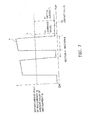
- FIG. 7 is a graph showing temporal changes in the instantaneous value and the average value of the GND current Ig inputted to the input ports 99a, 99b.
- the solid line graph A represents the instantaneous value of the GND current Ig inputted to the input port 99a
- the dashed line graph B represents the average value of the GND current Ig inputted to the input port 99b.
- the average value of the GND current Ig inputted to the input port 99b is substantially constant as shown in FIG.
- the instantaneous value of the GND current Ig inputted to the input port 99a has both sections where the instantaneous value is less than the average value of the GND current Ig and near 0A (section A in FIG. 7 ), and sections where the instantaneous value is greater than the average value of the GND current Ig (section B in FIG. 7 ).
- the reason for this is because the motor current Im is passed through the second fan motor 81 cyclically, whereas the drive current Id stays substantially constant (i.e., in a state near 0A), having been leveled by the current leveling unit 92 ( FIG. 6 ).
- the instantaneous value of the GND current Ig has a section containing only the drive current Id, wherein the motor current Im is not passed through the second fan motor 81, such as in section A.
- the calculation unit 99 determines the instantaneous value of the GND current Ig in a section where the value stays near 0A as in section A, i.e., an offset value Y2 in the instantaneous value of the GND current Ig as the drive current Id.
- the control unit 11 is a microcomputer configured from RAM, ROM, or another type of memory, and a CPU, and is disposed separately from the calculation unit 99 of the motor current detecting device 9 in the present embodiment.
- the control unit 11 is connected to the four-way switching valve 12, the expansion valve 13, the compressor driver 51, and the first motor driver 71 as shown in FIG. 8 , and the control unit 11 performs control for the devices to which it is connected.
- the control unit 11 performs pathway switching control for the four-way switching valve 12, drive control for the compressor driver 51 and the first motor driver 71, and other types of control.
- control unit 11 is also connected to the second fan motor device 8 and the motor current detecting device 9, and the control unit 11 performs a control for these devices. Specifically, the control unit 11 performs control of the volume of air sent into the room from the second fan 6b by performing rotational speed control of the second fan motor 81 on the basis of the motor current Im calculated by the calculation unit 99 of the motor current detecting device 9. For example, the control unit 11 generates a control signal for turning the switching elements in the second motor driver 82 on and off on the basis of the motor current Im so that the air volume into the room is substantially constant, and the control unit 11 outputs the generated control signal to the second fan motor device 8. A drive voltage based on the control signal from the control unit 11 is thereby outputted to the second fan motor 81 from the second motor driver 82 of the second fan motor device 8, and the second fan motor 81 rotates.
- control unit 11 controls the rotational speed of the second fan motor 81 and controls the air volume into the room by using the motor current Im, whereby it is possible to maintain substantial consistency in the air volume which is normally susceptible to the effects of factors such as the length of wire extending into the room from the second blowout opening 25 and the air pressure which varied depending on the width of the room interior.
- the motor current Im is calculated by the calculation unit 99 using the instantaneous value of the sum of the motor current Im and the drive current Id and the average value of the sum of the motor current Im and the drive current Id. Consequently, the accurate motor current Im can be determined.
- the calculation unit 99 determines the offset value Y2 in the instantaneous value of the sum of the motor current Im and the drive current Id (specifically, the instantaneous value where it is substantially near 0A) as the drive current Id, and calculates the motor current Im by subtracting the offset value Y2 of the instantaneous value from the average value Y1 of the sum of the motor current Im and the drive current Id.
- the motor current detecting device 9 can determine the motor current Im by a simple calculation.
- the calculation unit 99 in the motor current detecting device 9 has two input units 99a, 99b.
- the calculation unit 99 can thereby acquire the average value of the sum of the motor current Im and the drive current Id and the instantaneous value of the sum of the motor current Im and the drive current Id via the first input unit 99a and the second input unit 99b.
- the instantaneous current detecting unit 95 and the average current detecting unit 96 in the motor current detecting device 9 are configured from so-called filter circuits composed of resistors R2 to R5 and capacitors C2 to C4.
- the values of the resistors R2 to R5 and the capacitors C2 to C4 are determined so as to fulfill the condition that the first time constant of the instantaneous current detecting unit 95 be less than the second time constant of the average current detecting unit 96.
- the time constants are determined so as to enable detection of the instantaneous value of the sum of the motor current Im and the drive current Id or the average value of the sum of the motor current Im and the drive current Id.
- the instantaneous value of the sum of the motor current Im and the drive current Id and the average value of the sum of the motor current Im and the drive current Id can be detected by the instantaneous current detecting unit 95 and the average current detecting unit 96, which are physical means and which have simple configurations.
- the motor current detecting device 9 can calculate the motor current Im with precision because the motor current Im is determined using the instantaneous value of the sum of the motor current Im and the drive current Id and the average value of the sum of the motor current Im and the drive current Id.
- the motor current detecting device 9 further comprises the current leveling composed 92 for leveling the drive current Id before the drive current flows on the GND wire 93. Therefore, the motor current Im and an leveled drive current Id flow on the GND wire 93.
- the calculation unit 99 can thereby calculate an even more precise motor current Im because the instantaneous current detecting unit 95 and the average current detecting unit 96 respectively detect the instantaneous value and the average value of the sum of the motor current Im and the leveled drive current Id.
- the current leveling unit 92 in the motor current detecting device 9 can be configured from a so-called filter circuit composed of the resistor R1 and the capacitor C1.
- the motor current detecting device 9 is capable of leveling the drive current Id via the current leveling unit 92 having a simple configuration.
- the motor current detecting device 9 can be used for detecting the current of the second fan motor 81 in an air conditioning apparatus 1.
- the control unit 11 can perform control such that the volume of air sent a room is constant, for example, on the basis of an accurate motor current Im calculated by the motor current detecting device 9.
- the air conditioning apparatus 1 was a desiccant-type outdoor air conditioner comprising heat exchangers in the interior.
- the air conditioning apparatus according to the present invention can also be applied to a desiccant air conditioner in which the heat exchangers are disposed separately from the air conditioning apparatus, or an air conditioner using a system other than a desiccant system.
- the instantaneous current detecting unit 95 and the average current detecting unit 96 were configured from hardware composed of resistors R2 to R5 and capacitors C2 to C4.
- the instantaneous current detecting unit 95 and the average current detecting unit 96 may also be configured from software as long as they can respectively detect the instantaneous value and the average value of the GND current Ig.
- the configuration of the instantaneous current detecting unit 95 and the average current detecting unit 96 is not limited to that shown in FIG. 4 and may be any manner of configuration.
- the average current detecting unit 96 is configured from two resistors R4, R5 and two capacitors C3, C4, but may also be configured from one resistor and one capacitor as long as it is capable of detecting the average value of the GND current Ig.
- the motor current detecting device 9 included the current leveling unit 92 for leveling the drive current Id on the drive-use power supply wire 91.
- the motor current detecting device according to the present invention need not include the current leveling unit as long as it can detect the instantaneous value and the average value of the GND current Ig without leveling the drive current Id and can calculate the accurate motor current Im.
- the current leveling unit 92 was configured from filter composed of the resistor R1 and the capacitor C1.
- the current leveling unit may have any manner of configuration as long as it can level the drive current Id before the drive current Id flows on the GND wire 93.
- the calculation unit 99 and the control unit 11 were configured from separate microcomputers.
- the calculation unit 99 and the control unit 11 may be configured from a single microcomputer.
- the single microcomputer can function as the calculation unit 99 or the control unit 11 by reading and executing a motor current calculation program or various device control programs stored in ROM, an HDD, or another type of memory.
- the motor current detecting device 9 detected the motor current Im of the second fan motor 81 in the second fan motor device 8, but the application of the motor current detecting device according to the present invention is not limited to this example.
- the motor current detecting device according to the present invention can also be applied to a case in which the motor and the driver are provided separately, but instead of separately providing a motor current GND wire on which the motor current Im flows and a drive current GND wire on which the drive current Id flows, the motor current Im and the drive current Id flow on a single GND wire, for example.
- the motor current detecting device 9 detected a GND current Ig including the motor current Im passed through the second fan motor 81 and calculated the motor current Im from this GND current Ig in order to control the volume of supplying air SA supplied into the room.
- the objective of the current detection performed by the motor current detecting device according to the present invention need not be the second fan motor 81.
- the motor current detecting device may also be used to detect currents for the first fan motor 7 or the compressor-use motor 5, for example.
- the first fan motor 7 may be included with the first motor driver 71 in a fan motor device, similar to the second fan motor 81.
- a voltage detector 14 may be connected between the output of the motor-use power supply device 10a and GND as shown in FIG. 9 .
- the voltage detector 14 detects the voltage value of the power supply outputted from the motor-use power supply device 10a.
- the voltage value detected by the voltage detector 14 is sent to the control unit 11.
- the control unit 11 can thereby use the detected voltage value and the calculated motor current Im to calculate the motor power of the second fan motor 81. Consequently, the control unit 11 can use this motor power to perform various controls and the like on the second fan motor 81 and the other devices included in the air conditioning apparatus 1.
- a rotational speed detector 15 for detecting the rotational speed of the second fan motor 81 may also be provided as shown in FIG. 10
- This rotational speed detector 15 may be any type of detector, such as a type which is attached directly to the second fan motor device 8 and detects the rotational speed of the second fan motor 81, a type which detects the rotational speed by using an output signal from a Hall element for detecting the position of the rotor relative to the stator in the second fan motor 81, or a type which estimates the position of the rotor on the basis of the drive voltage outputted to the second fan motor 81 by the second motor driver 82 and uses the estimated rotor position to detect the rotational speed.
- the rotational speed detector 15 when the rotational speed detector 15 is not the type which is attached directly to the second fan motor device 8, the rotational speed detector 15 may be mounted either on the printed board P1 or on another printed board different from the printed board P1.
- FIG. 10 shows a case in which the rotational speed detector 15 is mounted on another printed board separate from the printed board P1.
- the rotational speed of the second fan motor 81 as detected by the rotational speed detector 15 is also sent to the control unit 11.
- the control unit 11 can thereby use the detected rotational speed of the second fan motor 81 and the calculated motor current Im to calculate the motor torque of the second fan motor 81. Consequently, the control unit 11 can use this motor torque to perform various controls and the like on the second fan motor 81 and other devices included in the air conditioning apparatus 1.
- the motor current detecting device has the effect of making it possible to precisely determine the motor current, and the motor current detecting device can be applied to an air conditioning apparatus.
Landscapes
- Engineering & Computer Science (AREA)
- Power Engineering (AREA)
- Air Conditioning Control Device (AREA)
- Control Of Motors That Do Not Use Commutators (AREA)
- Control Of Electric Motors In General (AREA)
- Measurement Of Current Or Voltage (AREA)
Abstract
Description
- The present invention relates to a motor current detecting device. The present invention also relates to an air conditioning apparatus comprising the motor current detecting device.
- An air conditioning apparatus comprises a compressor, a fan, and other various devices. A motor is often used as the power source for these devices. The motor is connected to a motor driver unit (called a "driver" below) composed of a plurality of switching elements, and the motor can be rotated by a drive voltage outputted by turning the switching elements in the driver ON and OFF.
- Further, sometimes the rotational speed of the motor is controlled to allow the various types of devices such as the compressor and the fan to operate in appropriate state. A motor current that is passed through the motor is often used for such motor rotational speed control. Here, as a method for detecting the motor current, for example, as disclosed in
Patent Document 1, there is known a technology where a shunt resistor serving as a current flows and where the motor current is detected on the basis of both end voltages of the shunt resistor.
<Patent Document 1> Japanese Laid-open Patent Application No.2005-192358 - Incidentally, other than when the motor and the driver are separately disposed, sometimes the motor and the driver are built into a motor device. However, in such a motor device, when the technology pertaining to
Patent Document 1 is applied to detect the motor current flowing in the motor portion, in terms of the configuration of that motor device, the drive current flowing through the driver ends up flowing in addition to the motor current on the wire where the shunt resistor is connected in series, so obtaining an accurate motor current ends up becoming difficult. - Thus, it is an object of the present invention to provide a motor current detecting device with which an accurate motor current can be obtained and an air conditioning apparatus comprising this motor current detecting device.
- A motor current detecting device according to a first aspect of the present invention comprises a first wire, an instantaneous current detecting unit, an average current detecting unit, and a calculation unit. On the first wire, a motor current that has been passed through a motor and a drive current that has been passed through a motor drive unit for driving the motor. The instantaneous current detecting unit detects an instantaneous value of the sum of the motor current and the drive current flowing on the first wire. The average current detecting unit detects an average value of the sum of the motor current and the drive current flowing on the first wire. The calculation unit calculates the motor current on the basis of the detection results of the instantaneous current detecting unit and the average current detecting unit.
- According to this motor current detecting device, the motor current is calculated using the instantaneous value of the sum of the motor current and the drive current and the average value of the sum of the motor current and the drive current. Therefore, the accurate motor current can be determined.
- The motor current detecting device according to a second aspect of the present invention is the motor current detecting device according to the first aspect of the present invention, wherein the calculation unit determines an offset value in the instantaneous value of the sum of the motor current and the drive current as the drive current, and calculates the motor current by subtracting the offset value in the instantaneous value from the average value of the sum of the motor current and the drive current.
- The phrase "offset value in the instantaneous value" herein refers to the instantaneous value being substantially near 0A. According to this motor current detecting device, the motor current is determined by subtracting the offset value from the average value of the sum of the motor current and the drive current. Thus, the motor current detecting device is capable of determining the motor current through a simple calculation.
- The motor current detecting device according to a third aspect of the present invention is the motor current detecting device according to the first or second aspect, further comprising a second wire and a third wire. The second wire is a wire for transferring to the calculation unit the instantaneous value of the sum of the motor current and the drive current detected by the instantaneous current detecting unit. The third wire is a wire for transferring to the calculation unit the average value of the sum of the motor current and the drive current detected by the average current detecting unit. The calculation unit has a first input unit and a second input unit. The first input unit is connected to the second wire, whereby the instantaneous value of the sum of the motor current and the drive current is inputted. The second input unit is connected to the third wire, whereby the average value of the sum of the motor current and the drive current is inputted.
- According to this motor current detecting device, the calculation unit can acquire the average value of the sum of the motor current and the drive current and the instantaneous value of the sum of the motor current and the drive current via the first input unit and the second input unit.
- The motor current detecting device according to a fourth aspect of the present invention is the motor current detecting device according to the third aspect, further comprising a current detecting unit. The current detecting unit detects the sum of the motor current and the drive current flowing on the first wire. The instantaneous current detecting unit has first resistors and a first capacitor. The first resistors are connected in series between the current detecting unit and the second wire. The first capacitor is connected in parallel to the first resistors. The average current detecting unit has second resistors and second capacitors. The second resistors are connected in series between the current detecting unit and the third wire. The second capacitors are connected in parallel to the second resistors. A first time constant of the first resistors and the first capacitor is less than a second time constant of the second resistors and the second capacitors.
- According to this motor current detecting device, the instantaneous current detecting unit and the average current detecting unit are configured from so-called filter circuits composed of resistors and capacitors, and the time constants of the filter circuits are determined so that the instantaneous value of the sum of the motor current and the drive current or the average value of the sum of the motor current and the drive current can be detected. Thus, the instantaneous value of the sum of the motor current and the drive current and the average value of the sum of the motor current and the drive current can be detected by an instantaneous current detecting unit and an average current detecting unit which are physical means and which have simple configurations.
- The motor current detecting device according to a fifth aspect of the present invention is the motor current detecting device according to any of the first through fourth aspects, wherein the motor and the motor drive unit are included in a motor device.
- When the motor and the motor drive unit are built into the motor device, in terms of the configuration thereof, it is difficult to separately dispose the wire on which the motor current that has been passed through the motor flows and the wire on which the drive current that has been passed through the motor drive unit flows. However, when the motor current detecting device according to the present invention is applied in such a case, the motor current detecting device can calculate the motor current with precision because the motor current is determined using the instantaneous value of the sum of the motor current and the drive current and the average value of the sum of the motor current and the drive current.
- The motor current detecting device according to a sixth aspect of the present invention is the motor current detecting device according to any of the first through fifth aspects, further comprising a current leveling unit. The current leveling unit levels the drive current before the drive current flows on the first wire.
- According to this motor current detecting device, on the first wire, the motor current and leveled drive current flow. Consequently, the instantaneous current detecting unit and the average current detecting unit respectively detect the instantaneous value of the sum of the motor current and the leveled drive current and the average value of the sum of the motor current and the leveled drive current, and the calculation unit can therefore calculate an even more precise motor current.
- The motor current detecting device according to a seventh aspect of the present invention is the motor current detecting device according to the sixth aspect, further comprising a fourth wire. On the fourth wire, the drive current flows. The current leveling unit has a third resistor and a third capacitor. The third resistor is connected in series on the fourth wire. The third capacitor is connected to the fourth wire in parallel to the third resistor.
- The current leveling unit in this motor current detecting device is configured from a so-called filter circuit composed of resistor and capacitor. Thus, the motor current detecting device is capable of leveling the drive current by the current leveling unit having a simple configuration.
- An air conditioning apparatus according to an eighth aspect of the present invention comprises a motor current detecting device, a fan motor, a fan, and a control unit. The motor current detecting device is the motor current detecting device according to any of the first through seventh aspects. The fan motor is included in the motor drive unit together with the motor device, and the motor current is passed through the fan motor. The fan is driven to rotate by the fan motor. The control unit performs control the volume of air sent into a room from the fan on the basis of the motor current calculated by the calculation unit of the motor current detecting device.
- According to this air conditioning apparatus, it is possible to perform control such that the volume of air sent into a room is constant, for example, on the basis of an accurate motor current calculated by the motor current detecting device.
- With the motor current detecting device according to the first aspect, the motor current is calculated using the instantaneous value of the sum of the motor current and the drive current and the average value of the sum of the motor current and the drive current. Consequently, the accurate motor current can be determined.
- With the motor current detecting device according to the second aspect, the motor current is determined by subtracting the offset value from the average value of the sum of the motor current and the drive current. Thus, the motor current detecting device can determine the motor current by a simple calculation.
- With the motor current detecting device according to the third aspect, the calculation unit can acquire the average value of the sum of the motor current and the drive current and the instantaneous value of the sum of the motor current and the drive current via the first input unit and the second input unit.
- With the motor current detecting device according to the fourth aspect, the instantaneous value of the sum of the motor current and the drive current and the average value of the sum of the motor current and the drive current are detected by the instantaneous current detecting unit and the average current detecting unit, which are physical means and which have simple configurations.
- With the motor current detecting device according to the fifth aspect, a precise motor current is obtained even in cases in which the motor and the motor drive unit are built into the motor device, because the motor current is determined using the instantaneous value of the sum of the motor current and the drive current and the average value of the sum of the motor current and the drive current.
- With the motor current detecting device according to the sixth aspect, the instantaneous current detecting unit and the average current detecting unit respectively detect the instantaneous value of the sum of the motor current and the leveled drive current and the average value of the sum of the motor current and the leveled drive current, and the calculation unit is therefore capable of calculating an even more precise motor current.
- With the motor current detecting device according to the seventh aspect, the drive current is leveled by the current leveling unit having a simple configuration.
- With the air conditioning apparatus according to the eighth aspect, it is possible to perform control such that the volume of air sent into a room is constant, for example, on the basis of an accurate motor current calculated by the motor current detecting device.
-
-
FIG. 1 is a schematic plan view showing the configuration of an air conditioning apparatus according to the present embodiment. -
FIG. 2 is a refrigerant circuit diagram of the air conditioning apparatus according to the present embodiment. -
FIG. 3 is a perspective view of the first and second heat exchangers provided to the air conditioning apparatus. -
FIG. 4 is a diagram showing the circuit configuration in a printed board equipped with the motor current detecting device according to the present embodiment, and the schematic configuration of a second fan motor device connected to the printed board. -
FIG. 5 is a graph showing temporal changes in the drive current Id', a motor current Im and a GND current Ig when a current leveling component is not disposed. -
FIG. 6 is a graph showing temporal changes in the drive current Id, the motor current Im and the GND current Ig when the drive current has been leveled using a current leveling unit. -
FIG 7 is a graph showing temporal changes in the instantaneous value and the average value of the GND current Ig. -
FIG. 8 is a block diagram schematically depicting the configuration of the air conditioning apparatus according to the present embodiment. -
FIG 9 is a diagram showing the internal circuit configuration of a printed board equipped with the motor current detecting device according to another embodiment (g), and the schematic configuration of the second fan motor device connected to this printed board. -
FIG 10 is a diagram showing the internal circuit configuration of a printed board equipped with the motor current detecting device according to another embodiment (h), and the schematic configuration of the second fan motor device connected to this printed board. -
- 1
- Air Conditioning Apparatus
- 2
- Casing
- 3a
- First Heat Exchanger
- 3b
- Second Heat Exchanger
- 4
- Compressor
- 5
- Compressor Motor
- 6a
- First Fan
- 6b
- Second Fan
- 7
- First Fan Motor
- 8
- Second Fan Motor Device
- 9
- Motor Current Detection Device
- 10a
- Motor-use Power Supply Device
- 10b
- Drive-use Power Supply Device
- 11
- Control Unit
- 71
- First Motor Driver
- 81
- Second Fan Motor
- 82
- Second Motor Driver
- 90
- Motor Power Supply Wire
- 91
- Drive Power Supply Wire
- 92
- Current Leveling Unit
- 93
- GND Wire
- 94
- Current Detecting Unit
- 95
- Instantaneous Current Detecting Unit
- 96
- Average Current Detecting Unit
- 97
- Instantaneous Current Transmission Line
- 98
- Average Current Transmission Line
- 99
- Calculation Unit
- 99a, 99b
- Input Ports
- R1, R2, R3, R4, R5
- Resistors
- C1, C2, C3, C4
- Capacitors
- Rs
- Shunt Resistor
- OP1
- Op-Amp
- Im
- Motor Current
- Id
- Drive Current
- Ig
- GND Current
- The following is a description, made with reference to the drawings, of a motor current detecting device according to the present invention and an air conditioning apparatus comprising this motor current detecting device.
-
FIG. 1 is a schematic plan view showing the configuration of anair conditioning apparatus 1 according to an embodiment of the present invention. Theair conditioning apparatus 1 ofFIG. 1 is a desiccant-type outdoor air conditioner wherein silica gel or another adsorptive agent is maintained on the surfaces of heat exchangers, and the air supplied to indoor space is subjected to a cooling and dehumidifying operation or a heating and humidifying operation. - This type of air-
conditioning apparatus 1 comprises mainly acasing 2, first andsecond heat exchangers compressor 4, acompressor motor 5, first andsecond fans 6a, 6b, a first fan motor 7, a secondfan motor device 8, a motor current detectingdevice 9, and acontrol unit 11, as shown inFIGS. 1 through 4 andFIG. 8 . Thefirst heat exchanger 3a, thesecond heat exchanger 3b, and thecompressor 4 constitute a refrigerant circuit such as the one shown inFIG. 2 . - The
casing 2 has a substantially rectangular parallelepiped shape, inside which are housed the first andsecond heat exchangers compressor 4, the first andsecond fans 6a, 6b, and other components. InFIG. 1 , in a leftside surface plate 21a of thecasing 2 are formed afirst suction opening 22 for sucking outdoor air OA into the interior of thecasing 2 and a second suction opening 23 for sucking room air RA into the interior of thecasing 2. In a rightside surface plate 21 b of thecasing 2 are formed a first blowout opening 24 for blowing out exhaust air EA to the outdoor and a second blowout opening 25 for supplying air SA after humidity conditioning to the room. A duct that extends into the room is connected to the second blowout opening 25, and the supplying air SA after being humidity-conditioned to the room through this duct. - A
partitioning plate 26 for partitioning the interior of thecasing 2 is provided inside thecasing 2. The interior of thecasing 2 is divided by thispartitioning plate 26 into an air chamber S1 and a machine chamber S2. The first andsecond heat exchangers heat exchangers second heat exchangers compressor 4, the first andsecond fans 6a, 6b, etc.) are disposed in the machine chamber S2. - The
first heat exchanger 3a and thesecond heat exchanger 3b are cross-fin type fin-and-tube heat exchangers, comprising numerous aluminum fins 31 formed into substantially rectangular plate shapes, and copperheat transfer tubes 32 passing through the fins 31 as shown inFIG. 3 . An absorptive agent which adsorbs the moisture contained in the air passing through theheat exchangers heat transfer tubes 32. The adsorptive agent herein can be zeolite, silica gel, active carbon, a hydrophilic or water-absorbing organic macromolecular polymer-based material, an ion-exchange resin-based material having a carboxylic group or sulfonic group, a temperature-sensitive polymer or another functional polymer material, or the like. - These first and
second heat exchangers expansion valve 13 as shown inFIG. 2 . For example, thefirst heat exchanger 3a conducts heat exchange with the room air RA taken in through the second suction opening 23, and thesecond heat exchanger 3b conducts heat exchange with the outdoor air OA taken in through thefirst suction opening 22. The room air RA after heat exchange is exhausted to the outdoors as exhaust air EA, and the outdoor air OA after heat exchange is supplied into the room as supplying air SA. - The first and
second heat exchangers control unit 11 so as to enable a first state in which thefirst heat exchanger 3a functions as a condenser and thesecond heat exchanger 3b functions as an evaporator, or a second state in which thefirst heat exchanger 3a functions as an evaporator and thesecond heat exchanger 3b functions as a condenser. In the first state, an adsorptive agent reproducing action is performed for removing moisture from the adsorptive agent when thefirst heat exchanger 3a functions as a condenser, and an adsorption action is performed for causing moisture to adsorb to the adsorptive agent when thesecond heat exchanger 3b functions as an evaporator. In the second state, an adsorption action is performed for causing moisture to adsorb to the adsorptive agent when thefirst heat exchanger 3a functions as an evaporator, and an adsorptive agent reproducing action is performed for removing moisture from the adsorptive agent when thesecond heat exchanger 3b functions as a condenser. By alternatively performing the adsorption action and the reproducing action in this manner and switching the flow channels of the air EA, SA supplied in and out of the room through theheat exchangers air conditioning apparatus 1 can perform various operations while maintaining dehumidification performance or humidification performance. - The flow channels of the air EA, SA supplied in and out of the room through the
heat exchangers blowout opening port 24 or the secondblowout opening port 25 after passing through either thefirst heat exchanger 3a or thesecond heat exchanger 3b. - The
compressor 4 is connected to thefirst heat exchanger 3a and thesecond heat exchanger 3b via a four-way switching valve 12 as shown inFIG. 2 . Thecompressor 4 compresses refrigerant from thefirst heat exchanger 3a orsecond heat exchanger 3b functioning as an evaporator. Thecompressor 4 performing a compressing action is driven by the compressor-use motor 5. - The compressor-
use motor 5 is connected to thecompressor 4. The compressor-use motor 5 is a brushless DC motor, for example, and is driven to rotate by a driver 51 (FIG. 8 ) for the compressor-use motor 5. - The first fan 6a is disposed in a position corresponding to the
first blowout opening 24, and the exhaust air EA is blown outside of the casing 2 (specifically, the outdoors) via the first blowout opening 24 as shown inFIG. 1 . Thesecond fan 6b is disposed in a position corresponding to the second blowout opening 25, and the supplying air SA is blown outside of the casing 2 (specifically, into the room) via thesecond blowout opening 25. The first fan 6a is driven to rotate by the first fan motor 7 (FIG. 8 ), and thesecond fan 6b is driven to rotate by the secondfan motor device 8. - The first fan motor 7 is connected to the first fan 6a. Like the
compressor motor 5, the first fan motor 7 is a brushless DC motor for example, and is controlled to rotate by afirst motor driver 71 for the first fan motor 7. The secondfan motor device 8 is connected to thesecond fan 6b, and is a device including asecond fan motor 81 and a second motor driver 82 (equivalent to a motor drive unit) as shown inFIGS. 4 and8 . Thesecond fan motor 81 is a brushless DC motor for example, specifically having a rotor composed of a permanent magnet having a plurality of magnetic poles, and a stator having a drive coil. Thesecond motor driver 82 is for driving thesecond fan motor 81 to rotate and includes a switching element for passing a current through the drive coil of thesecond fan motor 81. Thesecond motor driver 82 configured in this manner outputs to the second fan motor 81 a drive voltage corresponding to the position of the rotor relative to the stator. - The motor current detecting
device 9 is for detecting a motor current Im passed through thesecond fan motor 81, and the motor current detectingdevice 9 is mounted on a printed board P1 together with a motor-usepower supply device 10a that generates power for supply to the second fan motor 81 (hereinafter called "motor-use power ") and a drivepower supply device 10b that generates power for supply to the second motor driver 82 (hereinafter called "drive-use power"). Here, examples of type of the motor-usepower supply device 10a and the drive-usepower supply device 10b include a dropper power supply and a switching power supply. The printed board P1 and the secondfan motor device 8 are connected by three harnesses L1, L2, L3 between the interface of the printed board P1 and the interface of the secondfan motor device 8. Two harnesses L1, L2 of these three harnesses L1 to L3 are harnesses for the power outputted from each of thepower supply devices fan motor device 8. - The configuration of the motor current detecting
device 9 according to the present embodiment is described below mainly usingFIG. 4 . The motor current detectingdevice 9 comprises a motor-usepower supply wire 90, a drive-use power supply wire 91 (equivalent to a fourth wire), acurrent leveling unit 92, a GND wire 93 (equivalent to a first wire), a current detecting unit(detector) 94, an instantaneous current detecting unit(detector) 95, an average current detecting unit(detector) 96, an instantaneous current transmission line 97 (equivalent to a second wire), an average current transmission line 98 (equivalent to a third wire), and acalculation unit 99. - The motor-use
power supply wire 90 is a wire joining the output of the motor-usepower supply device 10a and the interface of the printed board P1, and a motor-use power supply outputted from the motor-usepower supply device 10a is applied thereto. The motor power supply is applied to thesecond fan motor 81 of the secondfan motor device 8 via the harness L1. Therefore, the motor current Im passed through thesecond fan motor 81 flows on the motor-usepower supply wire 90. - The drive-use
power supply wire 91 is a wire joining the output of the drive-usepower supply device 10b and the interface of the printed board P1, and a drive-use power supply outputted from the drive-usepower supply device 10b is applied thereto. This drive power supply is applied to thesecond motor driver 82 of the secondfan motor device 8 via the harness L2. Therefore, a drive current Id passed through thesecond motor driver 82 flows on the drive-usepower supply wire 91. - The
current leveling unit 92 levels the drive current Id before it flows on theGND wire 93, i.e., the drive current Id flowing on the drive-usepower supply wire 91. Thecurrent leveling unit 92 is configured from a filter circuit composed of a resistor R1 (equivalent to a third resistor) and a capacitor C1 (equivalent to a third capacitor). The resistor R1 is connected in series on the drive-usepower supply wire 91, and the capacitor C1 is connected to the drive-usepower supply wire 91 in parallel to the resistor R1. More specifically, one end q1 of the capacitor C1 is connected to the drive-usepower supply wire 91 on the drive current Id downstream side of the resistor R1, and another end q2 is connected to theGND wire 93. - The resistance value of the resistor R1 and the capacitance value of the capacitor C I are herein determined as follows, for example. First, in a drive current Id' when the
current leveling unit 92 is not disposed, the drive current Id' particularly changes, so a frequency f of the portion that should be leveled is measured (FIG. 5 ). Then, the resistance value of the resistor R1 and the capacitance value of the capacitor C1 are determined such that this frequency f becomes substantially equal to a time constant of the resistor R1 and the capacitor C1. The drive current Id' is leveled in this manner shown inFIG. 6 by a filter circuit configured from the resistor R1 and capacitor C1 thus determined. - The
GND wire 93 is a wire joining the GND of thepower supply devices fan motor device 8 via the harness L3. Therefore, the motor current Im passed through thesecond fan motor 81 and the drive current Id leveled by thecurrent leveling unit 92 and passed through thesecond motor driver 82 both flow through theGND wire 93. For the sake of convenience in the description, the current flowing the GND wire 93 (i.e., the motor current Im and the leveled drive current Id) will be called a GND current Ig below. - The current detecting
unit 94 detects the GND current Ig flowing on theGND wire 93, i.e., the sum of the motor current Im and the leveled drive current Id. The current detectingunit 94 is mainly configured by a shunt resistor Rs, an op-amp OP1, and other units. The shunt resistor Rs is connected in series to theGND wire 93. More specifically, the shunt resistor Rs is connected to theGND wire 93 on the GND current Ig downstream side of the other end q2 of the capacitor C1 in thecurrent leveling unit 92. Two input terminals of the op-amp OP1 are connected to both end portions of the shunt resistor Rs, and the output terminal is connected to the instantaneous current detectingunit 95 and the average current detectingunit 96. In this op-amp OP1, when the voltage inputted via the input terminals is amplified by a predetermined gain, the resulting voltage is outputted to the instantaneous current detectingunit 95 and the average current detectingunit 96. - The instantaneous current detecting
unit 95 detects an instantaneous value of the GND current Ig on theGND wire 93 as detected by the current detectingunit 94, i.e., an instantaneous value of the sum of the motor current Im and the leveled drive current Id. The instantaneous current detectingunit 95 is configured from two resistors R2, R3 (equivalent to a first resistor) and one capacitor C2 (equivalent to a first capacitor). The two resistors R2, R3 are connected in series between the current detectingunit 94 and the instantaneouscurrent transmission line 97. The capacitor C2 is connected in parallel to the resistors R2, R3. More specifically, one end of the capacitor C2 is connected between the two resistors R2, R3, and the other end is connected to GND. - The average current detecting
unit 96 detects the average value of the GND current Ig on theGND wire 93 as detected by the current detectingunit 94, i.e., the average value of the sum of the motor current Im and the leveled drive current Id. The average current detectingunit 96 is configured from two resistors R4, R5 (equivalent to a second resistor) and two capacitors C3, C4 (equivalent to a second capacitor). The two resistors R4, R5 are connected in series between the current detectingunit 94 and the averagecurrent transmission line 98. The two capacitors C3, C4 are connected in parallel to the resistors R4, R5, respectively. More specifically, one end of the capacitor C3 is connected between the two resistors R4, R5, and the other end is connected to GND. One end of the capacitor C4 is connected between the resistor R5 and the averagecurrent transmission line 98, and the other end is connected to GND. - The resistance values of the resistors R2, R3 and the capacitance value of the capacitor C2 of the instantaneous current detecting
unit 95 described above are determined to be values whereby the instantaneous value of the GND current Ig can be detected, and the resistance values of the resistors R4, R5 and the capacitance values of the capacitors C3, C4 of the average current detectingunit 96 are determined to be values whereby the average value of the GND current Ig can be detected. More specifically, the values of the resistors R2 to R5 and of the capacitors C2 to C4 are determined so that the first time constant of the resistors R2, R3 and the capacitor C2 in the instantaneous current detectingcomponent 95 is less than the second time constant of the resistors R4, R5 and the capacitors C3, C4 in the average current detectingunit 96. - The instantaneous
current transmission line 97 is a line for transferring the instantaneous value of the GND current Ig detected by the instantaneous current detectingunit 95 to thecalculation unit 99, and for connecting the output of the instantaneous current detectingunit 95 with aninput port 99a (equivalent to a first input unit) of thecalculation unit 99. - The average
current transmission line 98 is a line for transferring the average value of the GND current Ig detected by the average current detectingunit 96 to thecalculation unit 99, and for connecting the output of the average current detectingunit 96 with aninput port 99b (equivalent to a second input unit) of thecalculation unit 99. - The
calculation unit 99 is a microcomputer configured from RAM, ROM, or another type of memory, and a CPU. Thecalculation unit 99 calculates the motor current Im on the basis of the detection results of the instantaneous current detectingunit 95 and the average current detectingunit 96. Thecalculation unit 99 has twoinput ports input port 99a of the twoinput ports current transmission line 97, and the instantaneous value of the GND current Ig is inputted. Theother input port 99b is connected to the averagecurrent transmission line 98, and the average value of the GND current Ig is inputted. In thiscalculation unit 99, when the instantaneous value and average value of the GND current Ig are acquired via theinput ports -
FIG 7 is used herein to describe the manner in which thecalculation unit 99 calculates the motor current Im.FIG. 7 is a graph showing temporal changes in the instantaneous value and the average value of the GND current Ig inputted to theinput ports FIG. 7 , the solid line graph A represents the instantaneous value of the GND current Ig inputted to theinput port 99a, and the dashed line graph B represents the average value of the GND current Ig inputted to theinput port 99b. The average value of the GND current Ig inputted to theinput port 99b is substantially constant as shown inFIG. 7 , while the instantaneous value of the GND current Ig inputted to theinput port 99a has both sections where the instantaneous value is less than the average value of the GND current Ig and near 0A (section A inFIG. 7 ), and sections where the instantaneous value is greater than the average value of the GND current Ig (section B inFIG. 7 ). The reason for this is because the motor current Im is passed through thesecond fan motor 81 cyclically, whereas the drive current Id stays substantially constant (i.e., in a state near 0A), having been leveled by the current leveling unit 92 (FIG. 6 ). Therefore, the instantaneous value of the GND current Ig has a section containing only the drive current Id, wherein the motor current Im is not passed through thesecond fan motor 81, such as in section A. Thecalculation unit 99 then determines the instantaneous value of the GND current Ig in a section where the value stays near 0A as in section A, i.e., an offset value Y2 in the instantaneous value of the GND current Ig as the drive current Id. Thecalculation unit 99 calculates the motor current Im by subtracting the drive current Id, i.e. the offset value Y2 in the instantaneous value from the average value Y1 of the GND current Ig (Im = Y1 - Y2). - The
control unit 11 is a microcomputer configured from RAM, ROM, or another type of memory, and a CPU, and is disposed separately from thecalculation unit 99 of the motor current detectingdevice 9 in the present embodiment. Thecontrol unit 11 is connected to the four-way switching valve 12, theexpansion valve 13, thecompressor driver 51, and thefirst motor driver 71 as shown inFIG. 8 , and thecontrol unit 11 performs control for the devices to which it is connected. For example, thecontrol unit 11 performs pathway switching control for the four-way switching valve 12, drive control for thecompressor driver 51 and thefirst motor driver 71, and other types of control. - Particularly, the
control unit 11 according to the present embodiment is also connected to the secondfan motor device 8 and the motor current detectingdevice 9, and thecontrol unit 11 performs a control for these devices. Specifically, thecontrol unit 11 performs control of the volume of air sent into the room from thesecond fan 6b by performing rotational speed control of thesecond fan motor 81 on the basis of the motor current Im calculated by thecalculation unit 99 of the motor current detectingdevice 9. For example, thecontrol unit 11 generates a control signal for turning the switching elements in thesecond motor driver 82 on and off on the basis of the motor current Im so that the air volume into the room is substantially constant, and thecontrol unit 11 outputs the generated control signal to the secondfan motor device 8. A drive voltage based on the control signal from thecontrol unit 11 is thereby outputted to thesecond fan motor 81 from thesecond motor driver 82 of the secondfan motor device 8, and thesecond fan motor 81 rotates. - As described above, the
control unit 11 controls the rotational speed of thesecond fan motor 81 and controls the air volume into the room by using the motor current Im, whereby it is possible to maintain substantial consistency in the air volume which is normally susceptible to the effects of factors such as the length of wire extending into the room from the second blowout opening 25 and the air pressure which varied depending on the width of the room interior. - With the motor current detecting
device 9 according to the present embodiment, the motor current Im is calculated by thecalculation unit 99 using the instantaneous value of the sum of the motor current Im and the drive current Id and the average value of the sum of the motor current Im and the drive current Id. Consequently, the accurate motor current Im can be determined. - With the motor current detecting
device 9 according to the present embodiment, thecalculation unit 99 determines the offset value Y2 in the instantaneous value of the sum of the motor current Im and the drive current Id (specifically, the instantaneous value where it is substantially near 0A) as the drive current Id, and calculates the motor current Im by subtracting the offset value Y2 of the instantaneous value from the average value Y1 of the sum of the motor current Im and the drive current Id. Thus, the motor current detectingdevice 9 can determine the motor current Im by a simple calculation. - The
calculation unit 99 in the motor current detectingdevice 9 has twoinput units calculation unit 99 can thereby acquire the average value of the sum of the motor current Im and the drive current Id and the instantaneous value of the sum of the motor current Im and the drive current Id via thefirst input unit 99a and thesecond input unit 99b. - The instantaneous current detecting
unit 95 and the average current detectingunit 96 in the motor current detectingdevice 9 are configured from so-called filter circuits composed of resistors R2 to R5 and capacitors C2 to C4. The values of the resistors R2 to R5 and the capacitors C2 to C4 are determined so as to fulfill the condition that the first time constant of the instantaneous current detectingunit 95 be less than the second time constant of the average current detectingunit 96. In other words, the time constants are determined so as to enable detection of the instantaneous value of the sum of the motor current Im and the drive current Id or the average value of the sum of the motor current Im and the drive current Id. Thus, the instantaneous value of the sum of the motor current Im and the drive current Id and the average value of the sum of the motor current Im and the drive current Id can be detected by the instantaneous current detectingunit 95 and the average current detectingunit 96, which are physical means and which have simple configurations. - When the
second fan motor 81 and thesecond motor driver 82 are built into the secondfan motor device 8, it is difficult to separately dispose the wire on which the motor current Im that has been passed through thesecond fan motor 81 and the wire on which the drive current Id that has been passed through thesecond motor driver 82 flow. However, when the motor current detectingdevice 9 according to the present embodiment is applied in such a case, the motor current detectingdevice 9 can calculate the motor current Im with precision because the motor current Im is determined using the instantaneous value of the sum of the motor current Im and the drive current Id and the average value of the sum of the motor current Im and the drive current Id. - The motor current detecting
device 9 according to the present embodiment further comprises the current leveling composed 92 for leveling the drive current Id before the drive current flows on theGND wire 93. Therefore, the motor current Im and an leveled drive current Id flow on theGND wire 93. Thecalculation unit 99 can thereby calculate an even more precise motor current Im because the instantaneous current detectingunit 95 and the average current detectingunit 96 respectively detect the instantaneous value and the average value of the sum of the motor current Im and the leveled drive current Id. - Particularly, the
current leveling unit 92 in the motor current detectingdevice 9 can be configured from a so-called filter circuit composed of the resistor R1 and the capacitor C1. Thus, the motor current detectingdevice 9 is capable of leveling the drive current Id via thecurrent leveling unit 92 having a simple configuration. - Furthermore, the motor current detecting
device 9 can be used for detecting the current of thesecond fan motor 81 in anair conditioning apparatus 1. Thus, with theair conditioning apparatus 1 using the motor current detectingdevice 9, thecontrol unit 11 can perform control such that the volume of air sent a room is constant, for example, on the basis of an accurate motor current Im calculated by the motor current detectingdevice 9. - In the embodiment described above, an example was described of a case in which the
air conditioning apparatus 1 was a desiccant-type outdoor air conditioner comprising heat exchangers in the interior. However, the air conditioning apparatus according to the present invention can also be applied to a desiccant air conditioner in which the heat exchangers are disposed separately from the air conditioning apparatus, or an air conditioner using a system other than a desiccant system. - In the embodiment described above, a case was described in which the instantaneous current detecting
unit 95 and the average current detectingunit 96 were configured from hardware composed of resistors R2 to R5 and capacitors C2 to C4. However, the instantaneous current detectingunit 95 and the average current detectingunit 96 may also be configured from software as long as they can respectively detect the instantaneous value and the average value of the GND current Ig. - In the case that the instantaneous current detecting
unit 95 and the average current detectingunit 96 are configured from hardware, the configuration of the instantaneous current detectingunit 95 and the average current detectingunit 96 is not limited to that shown inFIG. 4 and may be any manner of configuration. For example, inFIG. 4 , the average current detectingunit 96 is configured from two resistors R4, R5 and two capacitors C3, C4, but may also be configured from one resistor and one capacitor as long as it is capable of detecting the average value of the GND current Ig. - In the embodiment described above, a case was described in which the motor current detecting
device 9 included thecurrent leveling unit 92 for leveling the drive current Id on the drive-usepower supply wire 91. However, the motor current detecting device according to the present invention need not include the current leveling unit as long as it can detect the instantaneous value and the average value of the GND current Ig without leveling the drive current Id and can calculate the accurate motor current Im. - In the embodiment described above, a case was described in which the
current leveling unit 92 was configured from filter composed of the resistor R1 and the capacitor C1. However, the current leveling unit may have any manner of configuration as long as it can level the drive current Id before the drive current Id flows on theGND wire 93. - In the embodiment described above, an example of a case was described in which the
calculation unit 99 and thecontrol unit 11 were configured from separate microcomputers. However, thecalculation unit 99 and thecontrol unit 11 may be configured from a single microcomputer. In this case, the single microcomputer can function as thecalculation unit 99 or thecontrol unit 11 by reading and executing a motor current calculation program or various device control programs stored in ROM, an HDD, or another type of memory. - In the embodiment described above, a case was described in which the motor current detecting
device 9 detected the motor current Im of thesecond fan motor 81 in the secondfan motor device 8, but the application of the motor current detecting device according to the present invention is not limited to this example. The motor current detecting device according to the present invention can also be applied to a case in which the motor and the driver are provided separately, but instead of separately providing a motor current GND wire on which the motor current Im flows and a drive current GND wire on which the drive current Id flows, the motor current Im and the drive current Id flow on a single GND wire, for example. - In the embodiment described above, a case was described in which the motor current detecting
device 9 detected a GND current Ig including the motor current Im passed through thesecond fan motor 81 and calculated the motor current Im from this GND current Ig in order to control the volume of supplying air SA supplied into the room. However, the objective of the current detection performed by the motor current detecting device according to the present invention need not be thesecond fan motor 81. The motor current detecting device may also be used to detect currents for the first fan motor 7 or the compressor-use motor 5, for example. - The first fan motor 7 may be included with the
first motor driver 71 in a fan motor device, similar to thesecond fan motor 81. - In the embodiment described above, a
voltage detector 14 may be connected between the output of the motor-usepower supply device 10a and GND as shown inFIG. 9 . Thevoltage detector 14 detects the voltage value of the power supply outputted from the motor-usepower supply device 10a. The voltage value detected by thevoltage detector 14 is sent to thecontrol unit 11. Thecontrol unit 11 can thereby use the detected voltage value and the calculated motor current Im to calculate the motor power of thesecond fan motor 81. Consequently, thecontrol unit 11 can use this motor power to perform various controls and the like on thesecond fan motor 81 and the other devices included in theair conditioning apparatus 1. - In the embodiment described above, a
rotational speed detector 15 for detecting the rotational speed of thesecond fan motor 81 may also be provided as shown inFIG. 10 Thisrotational speed detector 15 may be any type of detector, such as a type which is attached directly to the secondfan motor device 8 and detects the rotational speed of thesecond fan motor 81, a type which detects the rotational speed by using an output signal from a Hall element for detecting the position of the rotor relative to the stator in thesecond fan motor 81, or a type which estimates the position of the rotor on the basis of the drive voltage outputted to thesecond fan motor 81 by thesecond motor driver 82 and uses the estimated rotor position to detect the rotational speed. Of the types described above, when therotational speed detector 15 is not the type which is attached directly to the secondfan motor device 8, therotational speed detector 15 may be mounted either on the printed board P1 or on another printed board different from the printed board P1.FIG. 10 shows a case in which therotational speed detector 15 is mounted on another printed board separate from the printed board P1. The rotational speed of thesecond fan motor 81 as detected by therotational speed detector 15 is also sent to thecontrol unit 11. - The
control unit 11 can thereby use the detected rotational speed of thesecond fan motor 81 and the calculated motor current Im to calculate the motor torque of thesecond fan motor 81. Consequently, thecontrol unit 11 can use this motor torque to perform various controls and the like on thesecond fan motor 81 and other devices included in theair conditioning apparatus 1. - The motor current detecting device according to the present invention has the effect of making it possible to precisely determine the motor current, and the motor current detecting device can be applied to an air conditioning apparatus.
Claims (8)
- A motor current detecting device (9) comprising:a first wire (93) on which a motor current that has been passed through a motor (81) and a drive current that has been passed through a motor drive unit (82) for driving the motor (81);an instantaneous current detecting unit (95) for detecting an instantaneous value of the sum of the motor current and the drive current flowing on the first wire (93);an average electric current detecting unit (96) for detecting an average value of the sum of the motor current and the drive current flowing on the first wire (93); anda calculation unit (99) for calculating the motor current on the basis of the detection results of the instantaneous current detecting unit (95) and the average current detecting unit (96).
- The motor current detecting device (9) according to claim 1, wherein
the calculation unit (99):determines an offset value in the instantaneous value of the sum of the motor current and the drive current as the drive current; andcalculates the motor current by subtracting the offset value in the instantaneous value from the average value of the sum of the motor current and the drive current. - The motor current detecting device (9) according to claim 1 or 2, further comprising:a second wire (97) for transferring to the calculation unit (99) the instantaneous value of the sum of the motor current and the drive current as detected by the instantaneous current detecting unit (95); anda third wire (98) for transferring to the calculation unit (99) the average value of the sum of the motor current and the drive current as detected by the average current detecting unit (96); whereinthe calculation unit (99) has:a first input unit (99a) connected to the second wire (97), whereby the instantaneous value of the sum of the motor current and the drive current is inputted; anda second input unit (99b) connected to the third wire (98), whereby the average value of the sum of the motor current and the drive current is inputted.
- The motor current detecting device (9) according to claim 3, further comprising:a current detecting unit (94) for detecting the sum of the motor current and the drive current flowing on the first wire (93); whereinthe instantaneous current detecting unit (95) has:first resistors (R2, R3) connected in series between the current detecting unit (94) and the second wire (97); anda first capacitor (C2) connected in parallel to the first resistors (R2, R3);the average current detecting unit (96) has:second resistors (R4, R5) connected in series between the current detecting unit (94) and the third wire (98); andsecond capacitors (C3, C4) connected in parallel to the second resistors (R4, R5);anda first time constant of the first resistors (R2, R3) and the first capacitor (C2) is less than a second time constant of the second resistors (R4, R5) and the second capacitors (C3, C4).
- The motor current detecting device (9) according to any of claims 1 through 4, wherein the motor (81) and the motor drive unit (82) are included in a motor device (83).
- The motor current detecting device (9) according to any of claims 1 through 5, further comprising:a current leveling unit (92) for leveling the drive current before the drive current flows on the first wire (93).
- The motor current detecting device (9) according to claim 6, further comprising:a fourth wire (91) on which the drive current flows; whereinthe current leveling unit (92) has a third resistor (R1) connected in series on the fourth wire (91), and a third capacitor (C1) connected to the fourth wire (91) in parallel to the third resistor (R1).
- An air conditioning apparatus (1) comprising:the motor current detecting device (9) according to any of claims 1 through 7;a fan motor (81) that is included in the motor device (83) together with the motor drive unit (82) and through which the motor current is passed;a fan (6b) that is driven to rotate by the fan motor (81); anda control unit (11) that performs control of the volume of air sent into a room from the fan (6b) on the basis of the motor current that has been calculated by the calculation unit (99) of the motor current detecting device (9).
Applications Claiming Priority (2)
| Application Number | Priority Date | Filing Date | Title |
|---|---|---|---|
| JP2007298474A JP4412392B2 (en) | 2007-11-16 | 2007-11-16 | Motor current detector and air conditioner |
| PCT/JP2008/070647 WO2009063927A1 (en) | 2007-11-16 | 2008-11-13 | Motor current detection device and air conditioning device |
Publications (3)
| Publication Number | Publication Date |
|---|---|
| EP2221955A1 true EP2221955A1 (en) | 2010-08-25 |
| EP2221955A4 EP2221955A4 (en) | 2017-07-19 |
| EP2221955B1 EP2221955B1 (en) | 2018-10-03 |
Family
ID=40638774
Family Applications (1)
| Application Number | Title | Priority Date | Filing Date |
|---|---|---|---|
| EP08850949.2A Not-in-force EP2221955B1 (en) | 2007-11-16 | 2008-11-13 | Motor current detection device and air conditioning device |
Country Status (7)
| Country | Link |
|---|---|
| US (1) | US9093915B2 (en) |
| EP (1) | EP2221955B1 (en) |
| JP (1) | JP4412392B2 (en) |
| KR (1) | KR101088725B1 (en) |
| CN (1) | CN101861695B (en) |
| AU (1) | AU2008321885B8 (en) |
| WO (1) | WO2009063927A1 (en) |
Cited By (1)
| Publication number | Priority date | Publication date | Assignee | Title |
|---|---|---|---|---|
| EP3226409A1 (en) * | 2016-03-28 | 2017-10-04 | Mitsubishi Heavy Industries, Ltd. | Power converting device and air conditioner |
Families Citing this family (6)
| Publication number | Priority date | Publication date | Assignee | Title |
|---|---|---|---|---|
| JP4301341B2 (en) * | 2007-11-16 | 2009-07-22 | ダイキン工業株式会社 | Motor current calculation device and air conditioner |
| CN104459270A (en) * | 2013-09-20 | 2015-03-25 | 天津中电华利电器科技集团有限公司 | Instantaneous current detecting device |
| JP6433656B2 (en) * | 2013-12-18 | 2018-12-05 | 三菱重工サーマルシステムズ株式会社 | Current value detection apparatus and current value detection method |
| KR101691793B1 (en) * | 2015-07-10 | 2017-01-09 | 엘지전자 주식회사 | Motor driving apparatus and home appliance including the same |
| KR102569439B1 (en) | 2017-09-25 | 2023-08-22 | 존슨 컨트롤스 테크놀러지 컴퍼니 | Variable speed drive input current control |
| CN109142938B (en) * | 2018-07-17 | 2021-03-16 | 格力电器(武汉)有限公司 | Method and equipment for detecting quality of air conditioner |
Family Cites Families (17)
| Publication number | Priority date | Publication date | Assignee | Title |
|---|---|---|---|---|
| DE3517694A1 (en) * | 1984-05-21 | 1985-11-21 | Mitsubishi Electric Corp | CONTROL CIRCUIT FOR AN INVERTER |
| JPH04207986A (en) * | 1990-11-30 | 1992-07-29 | Hitachi Ltd | inverter device |
| TW328190B (en) * | 1994-06-14 | 1998-03-11 | Toshiba Co Ltd | Control device of brushless motor and method of fault detection and air conditioner |
| JP3023647B2 (en) * | 1994-11-18 | 2000-03-21 | 株式会社三社電機製作所 | Inverter for grid connection |
| JP3695889B2 (en) * | 1997-04-15 | 2005-09-14 | 株式会社東芝 | Inverter device |
| JPH11341878A (en) * | 1998-05-29 | 1999-12-10 | Matsushita Electric Ind Co Ltd | Motor control device |
| JP3610897B2 (en) | 2000-09-14 | 2005-01-19 | 三菱電機株式会社 | INVERTER DEVICE, COMPRESSOR DRIVE DEVICE, REFRIGERATION / AIR CONDITIONER, INVERTER DEVICE CONTROL METHOD |
| US6931239B2 (en) * | 2001-07-30 | 2005-08-16 | Hitachi Kokusai Electric Inc. | Peak limiter and multi-carrier amplification apparatus |
| EP2113999A3 (en) * | 2001-09-25 | 2010-01-06 | Daikin Industries, Ltd. | Phase current detection apparatus |
| US7221121B2 (en) * | 2001-11-23 | 2007-05-22 | Danfoss Drives A/S | Frequency converter for different mains voltages |
| JP4396270B2 (en) | 2003-12-26 | 2010-01-13 | 株式会社豊田自動織機 | Inverter device and motor control method |
| GB0415511D0 (en) * | 2004-07-10 | 2004-08-11 | Trw Ltd | Motor drive voltage-boost control |
| JP2007037275A (en) * | 2005-07-27 | 2007-02-08 | Hitachi Ltd | Motor drive device also serving as a charge control device |
| EP1753108A3 (en) * | 2005-08-10 | 2009-06-17 | International Rectifier Corporation | Method and apparatus for sensing brushless DC motor average current from overcurrent protection circuitry |
| CN100428621C (en) * | 2006-01-13 | 2008-10-22 | 海尔集团公司 | A brushless DC motor frequency conversion control device |
| JP4759422B2 (en) * | 2006-03-27 | 2011-08-31 | 日立アプライアンス株式会社 | Power converter system and washing machine using the same |
| TWI321896B (en) * | 2006-09-26 | 2010-03-11 | Sunplus Technology Co Ltd | Torque compensation method and system for dc brushless motor |
-
2007
- 2007-11-16 JP JP2007298474A patent/JP4412392B2/en not_active Expired - Fee Related
-
2008
- 2008-11-13 CN CN2008801160706A patent/CN101861695B/en not_active Expired - Fee Related
- 2008-11-13 EP EP08850949.2A patent/EP2221955B1/en not_active Not-in-force
- 2008-11-13 US US12/742,117 patent/US9093915B2/en active Active
- 2008-11-13 WO PCT/JP2008/070647 patent/WO2009063927A1/en not_active Ceased
- 2008-11-13 KR KR1020107011496A patent/KR101088725B1/en not_active Expired - Fee Related
- 2008-11-13 AU AU2008321885A patent/AU2008321885B8/en not_active Ceased
Non-Patent Citations (1)
| Title |
|---|
| See references of WO2009063927A1 * |
Cited By (1)
| Publication number | Priority date | Publication date | Assignee | Title |
|---|---|---|---|---|
| EP3226409A1 (en) * | 2016-03-28 | 2017-10-04 | Mitsubishi Heavy Industries, Ltd. | Power converting device and air conditioner |
Also Published As
| Publication number | Publication date |
|---|---|
| AU2008321885B8 (en) | 2012-08-09 |
| US9093915B2 (en) | 2015-07-28 |
| WO2009063927A1 (en) | 2009-05-22 |
| CN101861695B (en) | 2013-03-13 |
| JP4412392B2 (en) | 2010-02-10 |
| US20100275627A1 (en) | 2010-11-04 |
| KR101088725B1 (en) | 2011-12-02 |
| KR20100071112A (en) | 2010-06-28 |
| JP2009124907A (en) | 2009-06-04 |
| AU2008321885B2 (en) | 2012-07-12 |
| EP2221955A4 (en) | 2017-07-19 |
| EP2221955B1 (en) | 2018-10-03 |
| CN101861695A (en) | 2010-10-13 |
| AU2008321885A1 (en) | 2009-05-22 |
Similar Documents
| Publication | Publication Date | Title |
|---|---|---|
| US9093915B2 (en) | Motor current detecting device and air conditioning apparatus | |
| EP2767772B1 (en) | Humidity control device | |
| WO2014057617A1 (en) | Humidity control and ventilation device | |
| CN101790665B (en) | Humidity controller | |
| AU2008320210B2 (en) | Humidity control apparatus | |
| US8400083B2 (en) | Current detecting device, air conditioning apparatus, correction constant calculating system and correction constant calculating method | |
| WO2007004446A1 (en) | Ventilator | |
| EP2221956B1 (en) | Motor current calculation device and air conditioning device | |
| JP2007010229A (en) | Ventilation equipment | |
| US9228751B2 (en) | Humidity controlling ventilator | |
| KR20130075614A (en) | Duct type air conditioner and method for controlling the same | |
| US9228753B2 (en) | Ventilation system | |
| JP4434254B2 (en) | Current detector and air conditioner | |
| JP2016156573A (en) | Air supply/exhaust type ventilator | |
| WO2007004559A1 (en) | Humidity control device | |
| JP2008145092A (en) | Humidity control device | |
| JP4458156B2 (en) | Signal correction device and air conditioner | |
| JP2002162052A (en) | Air conditioners and indoor heat exchangers | |
| JP2009195065A (en) | Power calculation device, air conditioner, and power calculation method |
Legal Events
| Date | Code | Title | Description |
|---|---|---|---|
| PUAI | Public reference made under article 153(3) epc to a published international application that has entered the european phase |
Free format text: ORIGINAL CODE: 0009012 |
|
| 17P | Request for examination filed |
Effective date: 20100610 |
|
| AK | Designated contracting states |
Kind code of ref document: A1 Designated state(s): AT BE BG CH CY CZ DE DK EE ES FI FR GB GR HR HU IE IS IT LI LT LU LV MC MT NL NO PL PT RO SE SI SK TR |
|
| AX | Request for extension of the european patent |
Extension state: AL BA MK RS |
|
| DAX | Request for extension of the european patent (deleted) | ||
| RA4 | Supplementary search report drawn up and despatched (corrected) |
Effective date: 20170620 |
|
| RIC1 | Information provided on ipc code assigned before grant |
Ipc: H02P 27/06 20060101AFI20170613BHEP Ipc: H02M 1/00 20070101ALI20170613BHEP |
|
| REG | Reference to a national code |
Ref country code: DE Ref legal event code: R079 Ref document number: 602008057273 Country of ref document: DE Free format text: PREVIOUS MAIN CLASS: H02P0006160000 Ipc: H02M0005420000 |
|
| GRAP | Despatch of communication of intention to grant a patent |
Free format text: ORIGINAL CODE: EPIDOSNIGR1 |
|
| RIC1 | Information provided on ipc code assigned before grant |
Ipc: F25B 49/02 20060101ALI20180424BHEP Ipc: H02M 1/00 20060101ALI20180424BHEP Ipc: H02M 5/42 20060101AFI20180424BHEP Ipc: H02P 27/06 20060101ALI20180424BHEP |
|
| STAA | Information on the status of an ep patent application or granted ep patent |
Free format text: STATUS: GRANT OF PATENT IS INTENDED |
|
| INTG | Intention to grant announced |
Effective date: 20180531 |
|
| GRAS | Grant fee paid |
Free format text: ORIGINAL CODE: EPIDOSNIGR3 |
|
| GRAA | (expected) grant |
Free format text: ORIGINAL CODE: 0009210 |
|
| STAA | Information on the status of an ep patent application or granted ep patent |
Free format text: STATUS: THE PATENT HAS BEEN GRANTED |
|
| AK | Designated contracting states |
Kind code of ref document: B1 Designated state(s): AT BE BG CH CY CZ DE DK EE ES FI FR GB GR HR HU IE IS IT LI LT LU LV MC MT NL NO PL PT RO SE SI SK TR |
|
| REG | Reference to a national code |
Ref country code: GB Ref legal event code: FG4D |
|
| REG | Reference to a national code |
Ref country code: CH Ref legal event code: EP Ref country code: AT Ref legal event code: REF Ref document number: 1049701 Country of ref document: AT Kind code of ref document: T Effective date: 20181015 |
|
| REG | Reference to a national code |
Ref country code: IE Ref legal event code: FG4D Ref country code: DE Ref legal event code: R096 Ref document number: 602008057273 Country of ref document: DE |
|
| REG | Reference to a national code |
Ref country code: NL Ref legal event code: MP Effective date: 20181003 |
|
| REG | Reference to a national code |
Ref country code: LT Ref legal event code: MG4D |
|
| REG | Reference to a national code |
Ref country code: AT Ref legal event code: MK05 Ref document number: 1049701 Country of ref document: AT Kind code of ref document: T Effective date: 20181003 |
|
| PG25 | Lapsed in a contracting state [announced via postgrant information from national office to epo] |
Ref country code: NL Free format text: LAPSE BECAUSE OF FAILURE TO SUBMIT A TRANSLATION OF THE DESCRIPTION OR TO PAY THE FEE WITHIN THE PRESCRIBED TIME-LIMIT Effective date: 20181003 |
|
| PG25 | Lapsed in a contracting state [announced via postgrant information from national office to epo] |
Ref country code: FI Free format text: LAPSE BECAUSE OF FAILURE TO SUBMIT A TRANSLATION OF THE DESCRIPTION OR TO PAY THE FEE WITHIN THE PRESCRIBED TIME-LIMIT Effective date: 20181003 Ref country code: NO Free format text: LAPSE BECAUSE OF FAILURE TO SUBMIT A TRANSLATION OF THE DESCRIPTION OR TO PAY THE FEE WITHIN THE PRESCRIBED TIME-LIMIT Effective date: 20190103 Ref country code: IS Free format text: LAPSE BECAUSE OF FAILURE TO SUBMIT A TRANSLATION OF THE DESCRIPTION OR TO PAY THE FEE WITHIN THE PRESCRIBED TIME-LIMIT Effective date: 20190203 Ref country code: AT Free format text: LAPSE BECAUSE OF FAILURE TO SUBMIT A TRANSLATION OF THE DESCRIPTION OR TO PAY THE FEE WITHIN THE PRESCRIBED TIME-LIMIT Effective date: 20181003 Ref country code: ES Free format text: LAPSE BECAUSE OF FAILURE TO SUBMIT A TRANSLATION OF THE DESCRIPTION OR TO PAY THE FEE WITHIN THE PRESCRIBED TIME-LIMIT Effective date: 20181003 Ref country code: LV Free format text: LAPSE BECAUSE OF FAILURE TO SUBMIT A TRANSLATION OF THE DESCRIPTION OR TO PAY THE FEE WITHIN THE PRESCRIBED TIME-LIMIT Effective date: 20181003 Ref country code: HR Free format text: LAPSE BECAUSE OF FAILURE TO SUBMIT A TRANSLATION OF THE DESCRIPTION OR TO PAY THE FEE WITHIN THE PRESCRIBED TIME-LIMIT Effective date: 20181003 Ref country code: CZ Free format text: LAPSE BECAUSE OF FAILURE TO SUBMIT A TRANSLATION OF THE DESCRIPTION OR TO PAY THE FEE WITHIN THE PRESCRIBED TIME-LIMIT Effective date: 20181003 Ref country code: LT Free format text: LAPSE BECAUSE OF FAILURE TO SUBMIT A TRANSLATION OF THE DESCRIPTION OR TO PAY THE FEE WITHIN THE PRESCRIBED TIME-LIMIT Effective date: 20181003 Ref country code: PL Free format text: LAPSE BECAUSE OF FAILURE TO SUBMIT A TRANSLATION OF THE DESCRIPTION OR TO PAY THE FEE WITHIN THE PRESCRIBED TIME-LIMIT Effective date: 20181003 Ref country code: BG Free format text: LAPSE BECAUSE OF FAILURE TO SUBMIT A TRANSLATION OF THE DESCRIPTION OR TO PAY THE FEE WITHIN THE PRESCRIBED TIME-LIMIT Effective date: 20190103 |
|
| PG25 | Lapsed in a contracting state [announced via postgrant information from national office to epo] |
Ref country code: PT Free format text: LAPSE BECAUSE OF FAILURE TO SUBMIT A TRANSLATION OF THE DESCRIPTION OR TO PAY THE FEE WITHIN THE PRESCRIBED TIME-LIMIT Effective date: 20190203 Ref country code: GR Free format text: LAPSE BECAUSE OF FAILURE TO SUBMIT A TRANSLATION OF THE DESCRIPTION OR TO PAY THE FEE WITHIN THE PRESCRIBED TIME-LIMIT Effective date: 20190104 Ref country code: SE Free format text: LAPSE BECAUSE OF FAILURE TO SUBMIT A TRANSLATION OF THE DESCRIPTION OR TO PAY THE FEE WITHIN THE PRESCRIBED TIME-LIMIT Effective date: 20181003 |
|
| REG | Reference to a national code |
Ref country code: CH Ref legal event code: PL |
|
| REG | Reference to a national code |
Ref country code: DE Ref legal event code: R097 Ref document number: 602008057273 Country of ref document: DE |
|
| PG25 | Lapsed in a contracting state [announced via postgrant information from national office to epo] |
Ref country code: LU Free format text: LAPSE BECAUSE OF NON-PAYMENT OF DUE FEES Effective date: 20181113 Ref country code: IT Free format text: LAPSE BECAUSE OF FAILURE TO SUBMIT A TRANSLATION OF THE DESCRIPTION OR TO PAY THE FEE WITHIN THE PRESCRIBED TIME-LIMIT Effective date: 20181003 Ref country code: DK Free format text: LAPSE BECAUSE OF FAILURE TO SUBMIT A TRANSLATION OF THE DESCRIPTION OR TO PAY THE FEE WITHIN THE PRESCRIBED TIME-LIMIT Effective date: 20181003 |
|
| PLBE | No opposition filed within time limit |
Free format text: ORIGINAL CODE: 0009261 |
|
| STAA | Information on the status of an ep patent application or granted ep patent |
Free format text: STATUS: NO OPPOSITION FILED WITHIN TIME LIMIT |
|
| REG | Reference to a national code |
Ref country code: BE Ref legal event code: MM Effective date: 20181130 |
|
| REG | Reference to a national code |
Ref country code: IE Ref legal event code: MM4A |
|
| PG25 | Lapsed in a contracting state [announced via postgrant information from national office to epo] |
Ref country code: CH Free format text: LAPSE BECAUSE OF NON-PAYMENT OF DUE FEES Effective date: 20181130 Ref country code: MC Free format text: LAPSE BECAUSE OF FAILURE TO SUBMIT A TRANSLATION OF THE DESCRIPTION OR TO PAY THE FEE WITHIN THE PRESCRIBED TIME-LIMIT Effective date: 20181003 Ref country code: LI Free format text: LAPSE BECAUSE OF NON-PAYMENT OF DUE FEES Effective date: 20181130 Ref country code: EE Free format text: LAPSE BECAUSE OF FAILURE TO SUBMIT A TRANSLATION OF THE DESCRIPTION OR TO PAY THE FEE WITHIN THE PRESCRIBED TIME-LIMIT Effective date: 20181003 Ref country code: RO Free format text: LAPSE BECAUSE OF FAILURE TO SUBMIT A TRANSLATION OF THE DESCRIPTION OR TO PAY THE FEE WITHIN THE PRESCRIBED TIME-LIMIT Effective date: 20181003 Ref country code: SK Free format text: LAPSE BECAUSE OF FAILURE TO SUBMIT A TRANSLATION OF THE DESCRIPTION OR TO PAY THE FEE WITHIN THE PRESCRIBED TIME-LIMIT Effective date: 20181003 |
|
| 26N | No opposition filed |
Effective date: 20190704 |
|
| PG25 | Lapsed in a contracting state [announced via postgrant information from national office to epo] |
Ref country code: SI Free format text: LAPSE BECAUSE OF FAILURE TO SUBMIT A TRANSLATION OF THE DESCRIPTION OR TO PAY THE FEE WITHIN THE PRESCRIBED TIME-LIMIT Effective date: 20181003 Ref country code: IE Free format text: LAPSE BECAUSE OF NON-PAYMENT OF DUE FEES Effective date: 20181113 |
|
| PG25 | Lapsed in a contracting state [announced via postgrant information from national office to epo] |
Ref country code: BE Free format text: LAPSE BECAUSE OF NON-PAYMENT OF DUE FEES Effective date: 20181130 |
|
| PG25 | Lapsed in a contracting state [announced via postgrant information from national office to epo] |
Ref country code: MT Free format text: LAPSE BECAUSE OF NON-PAYMENT OF DUE FEES Effective date: 20181113 |
|
| PG25 | Lapsed in a contracting state [announced via postgrant information from national office to epo] |
Ref country code: TR Free format text: LAPSE BECAUSE OF FAILURE TO SUBMIT A TRANSLATION OF THE DESCRIPTION OR TO PAY THE FEE WITHIN THE PRESCRIBED TIME-LIMIT Effective date: 20181003 |
|
| PG25 | Lapsed in a contracting state [announced via postgrant information from national office to epo] |
Ref country code: HU Free format text: LAPSE BECAUSE OF FAILURE TO SUBMIT A TRANSLATION OF THE DESCRIPTION OR TO PAY THE FEE WITHIN THE PRESCRIBED TIME-LIMIT; INVALID AB INITIO Effective date: 20081113 Ref country code: CY Free format text: LAPSE BECAUSE OF FAILURE TO SUBMIT A TRANSLATION OF THE DESCRIPTION OR TO PAY THE FEE WITHIN THE PRESCRIBED TIME-LIMIT Effective date: 20181003 |
|
| PGFP | Annual fee paid to national office [announced via postgrant information from national office to epo] |
Ref country code: GB Payment date: 20220930 Year of fee payment: 15 |
|
| PGFP | Annual fee paid to national office [announced via postgrant information from national office to epo] |
Ref country code: FR Payment date: 20221010 Year of fee payment: 15 |
|
| PGFP | Annual fee paid to national office [announced via postgrant information from national office to epo] |
Ref country code: DE Payment date: 20220621 Year of fee payment: 15 |
|
| P01 | Opt-out of the competence of the unified patent court (upc) registered |
Effective date: 20230525 |
|
| REG | Reference to a national code |
Ref country code: DE Ref legal event code: R119 Ref document number: 602008057273 Country of ref document: DE |
|
| GBPC | Gb: european patent ceased through non-payment of renewal fee |
Effective date: 20231113 |
|
| PG25 | Lapsed in a contracting state [announced via postgrant information from national office to epo] |
Ref country code: DE Free format text: LAPSE BECAUSE OF NON-PAYMENT OF DUE FEES Effective date: 20240601 |
|
| PG25 | Lapsed in a contracting state [announced via postgrant information from national office to epo] |
Ref country code: GB Free format text: LAPSE BECAUSE OF NON-PAYMENT OF DUE FEES Effective date: 20231113 |
|
| PG25 | Lapsed in a contracting state [announced via postgrant information from national office to epo] |
Ref country code: FR Free format text: LAPSE BECAUSE OF NON-PAYMENT OF DUE FEES Effective date: 20231130 |
|
| PG25 | Lapsed in a contracting state [announced via postgrant information from national office to epo] |
Ref country code: GB Free format text: LAPSE BECAUSE OF NON-PAYMENT OF DUE FEES Effective date: 20231113 Ref country code: FR Free format text: LAPSE BECAUSE OF NON-PAYMENT OF DUE FEES Effective date: 20231130 Ref country code: DE Free format text: LAPSE BECAUSE OF NON-PAYMENT OF DUE FEES Effective date: 20240601 |