EP2221820A2 - Disc apparatus - Google Patents
Disc apparatus Download PDFInfo
- Publication number
- EP2221820A2 EP2221820A2 EP10153040A EP10153040A EP2221820A2 EP 2221820 A2 EP2221820 A2 EP 2221820A2 EP 10153040 A EP10153040 A EP 10153040A EP 10153040 A EP10153040 A EP 10153040A EP 2221820 A2 EP2221820 A2 EP 2221820A2
- Authority
- EP
- European Patent Office
- Prior art keywords
- disc
- motor
- moved
- chassis
- traverse chassis
- Prior art date
- Legal status (The legal status is an assumption and is not a legal conclusion. Google has not performed a legal analysis and makes no representation as to the accuracy of the status listed.)
- Granted
Links
- 230000003287 optical effect Effects 0.000 claims description 7
- 230000003028 elevating effect Effects 0.000 description 5
- 230000004048 modification Effects 0.000 description 2
- 238000012986 modification Methods 0.000 description 2
- 238000004519 manufacturing process Methods 0.000 description 1
- 230000002035 prolonged effect Effects 0.000 description 1
Images



Classifications
-
- G—PHYSICS
- G11—INFORMATION STORAGE
- G11B—INFORMATION STORAGE BASED ON RELATIVE MOVEMENT BETWEEN RECORD CARRIER AND TRANSDUCER
- G11B17/00—Guiding record carriers not specifically of filamentary or web form, or of supports therefor
- G11B17/02—Details
- G11B17/022—Positioning or locking of single discs
- G11B17/028—Positioning or locking of single discs of discs rotating during transducing operation
- G11B17/0288—Positioning or locking of single discs of discs rotating during transducing operation by means for moving the turntable or the clamper towards the disk
-
- G—PHYSICS
- G11—INFORMATION STORAGE
- G11B—INFORMATION STORAGE BASED ON RELATIVE MOVEMENT BETWEEN RECORD CARRIER AND TRANSDUCER
- G11B17/00—Guiding record carriers not specifically of filamentary or web form, or of supports therefor
- G11B17/02—Details
- G11B17/04—Feeding or guiding single record carrier to or from transducer unit
- G11B17/05—Feeding or guiding single record carrier to or from transducer unit specially adapted for discs not contained within cartridges
- G11B17/053—Indirect insertion, i.e. with external loading means
- G11B17/056—Indirect insertion, i.e. with external loading means with sliding loading means
Definitions
- the disc tray is ejected in a case that clamp is not normally performed.
- the disc tray is also ejected in a case that a jam occurs in an elevating mechanism for transmitting the drive force of the motor to the traverse chassis. In this case, the user needs to perform operation of closing the disc tray again.
Landscapes
- Feeding And Guiding Record Carriers (AREA)
Abstract
Description
- This invention relates to a disc apparatus including a traverse chassis provided with a turn table.
- Various disc apparatus each including a disc tray on which a disc is placed, a main chassis provided with the disc tray so that the disc tray can move forward and backward, a traverse chassis provided with a turn table, and a motor for moving up and down the traverse chassis between an upper position and a lower position have been known (For example, refer to
Patent Documents 1 to 4). -
Patent Document 1 discloses a disc apparatus wherein a disc tray moves forward and backward in a state in which a traverse chassis is disposed in a lower position. In the disc apparatus, the traverse chassis is moved up to an upper position by a motor in a state in which the disc tray is housed in a main chassis. At this time, a turn table rises and thus a disc placed on the disc tray is clamped by the turn table and a clamper. In the disc apparatus, in a case that a clamp of the disc is not normally performed, the disc tray is ejected from the main chassis. -
Patent Document 2 discloses a disc apparatus wherein when a clamp state of a disc is released (unclamped), in a case that unclamp cannot be performed at a predetermined voltage, the unclamp is performed at a higher voltage than the predetermined voltage. - Patent Document 3 discloses a disc apparatus wherein, in a case that the necessary time for ejecting or housing a disc is prolonged, an applied voltage to a motor for driving a disc tray is increased.
-
Patent Document 4 discloses a disc apparatus wherein, in a case that a disc tray comes in contact with an obstacle when a disc tray is ejected, the disc tray is housed. - [Patent Document 1] Japanese Patent Publication No.
2007-213687 A - [Patent Document 2] Japanese Patent Publication No.
2007-58904 A - [Patent Document 3] Japanese Patent Publication No.
2008-34030 A - [Patent Document 4] Japanese Patent Publication No.
2008-84365 A - However, in the conventional disc apparatus disclosed in
Patent Document 1, the disc tray is ejected in a case that clamp is not normally performed. Thus, for example, there is a problem in that the disc tray is also ejected in a case that a jam occurs in an elevating mechanism for transmitting the drive force of the motor to the traverse chassis. In this case, the user needs to perform operation of closing the disc tray again. -
Patent Documents 2 to 4 do not disclose or suggest an operation of the disc apparatus in a case that clamp is not normally performed. - It is therefore one aspect of the present invention is to provide a disc apparatus capable of clamping a disc in a case that a jam occurs in an elevating mechanism.
- It is therefore another aspect of the present invention is to provide a disc apparatus capable of saving user's operation for accommodating or ejecting a disc tray again in a case that a jam occurs.
- According to one aspect of the invention, there is provided a disc apparatus, including:
- a main chassis;
- a disc tray, ejectably accommodated in the main chassis, and configured to mount a disc thereon;
- a motor configured to rotate in a first direction and a second direction opposite to the first direction;
- a traverse chassis, having a turn table for clamping the disc, and configured to be moved between a first position and a second position, wherein the traverse chassis is moved toward the first position by a rotation of the motor in the first direction and toward the second position by a rotation of the motor in the second direction;
- a detector configured to detect that the traverse chassis is disposed in a first position; and
- a controller configured to allow the motor to rotate,
wherein, in a case that the detector does not detect that the traverse chassis is disposed in the first position during the controller allows the motor to rotate in the first direction for a first time period, the controller allows the motor to rotate in the second direction for a second time period, and to rotate in the first direction again after an elapse of the second time period. - The disc apparatus may be configured such that a voltage supplied to the motor during the second time period is higher than a voltage supplied to the motor during that the traverse chassis is moved to the first position.
- The disc apparatus may be configured such that the disc is clamped when the traverse chassis is disposed in the first position, and is released when the traverse chassis is disposed in the second position, and the traverse chassis is moved to the first position after the disc tray is accommodated in the main chassis, and is moved to the second position before the disc tray is ejected from the main chassis.
- The disc apparatus may be configured such that the disc tray is ejected, in a case that the detector does not detect that the traverse chassis is disposed in the first position, after that the motor rotates in the first direction again after the elapse of the second time period.
- The disc apparatus may be configured such that the disc tray is moved into the main chassis by the rotation of the motor in the first direction and is moved so as to be ejected from the main chassis by the rotation of the motor in the second direction, in a condition that the traverse chassis is disposed in the second position.
- The disc apparatus may further includes an optical pickup, provided in the traverse chassis, and configured to be moved by a rotation of the motor in a condition that the disc is clamped.
- The disc apparatus may be configured such that the disc is released when the traverse chassis is disposed in the first position, and is clamped when the traverse chassis is disposed in the second position, and the traverse chassis is moved to the first position before the disc tray is ejected from the main chassis, and is moved to the second position after the disc tray is accommodated in the main chassis.
-
-
Fig. 1 is a plan view of a disc apparatus according to one embodiment of the invention. -
Fig. 2 is a side view showing a state in which a traverse chassis of the disc apparatus shown inFig. 1 is disposed in an upper position. -
Fig. 3 is a plan view of the disc apparatus shown inFig. 1 in a state that a disc tray and a beam part are omitted. -
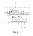
Fig. 4 is a front view of the disc apparatus shown inFig. 1 . -
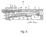
Fig. 5 is a side view showing a state in which the traverse chassis of the disc apparatus shown inFig. 1 is disposed in a lower position. -
Fig. 6A is a timing chart when the disc tray of the disc apparatus according to the embodiment of the invention is housed normally. -
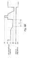
Fig. 6B is a timing chart when a clamp of a disc placed on the disc tray of the disc apparatus according to the embodiment of the invention is failed. - Exemplified embodiments of the invention are described below in detail with reference to the accompanying drawings.
- A configuration of a
disc apparatus 100 according to the embodiment of the invention will be discussed with reference toFigs. 1 to 4 . - As shown in
Fig. 1 , thedisc apparatus 100 according to the embodiment includes adisc tray 1 where a disc such as a CD, a DVD, etc., (not shown) is placed, amain chassis 2 provided with thedisc tray 1 so that the disc tray can be moved forward and backward, a traverse chassis 3 provided so as to be able to be moved up and down between an upper position and a lower position in themain chassis 2, and aslide member 4 provided so as be able to move in an arrow X1 direction and an arrow X2 direction. An arrow Y1 direction shown inFig. 1 is a direction in which the disc tray is moved backward, and an arrow Y2 shown inFig. 1 is a direction in which the disc tray is moved forward. The arrow X1 direction is orthogonal to the arrow Y1 direction, and the arrow X2 direction is opposite to the arrow X1 direction. - In a state in which the traverse chassis 3 is disposed in the lower position, the
disc tray 1 is moved in the arrow Y1 direction and is housed in themain chassis 2, and thedisc tray 1 moves in the arrow Y2 direction and is ejected from themain chassis 2. Thedisc tray 1 has a lower face formed withguide grooves rack gear 13. Each of theguide grooves rack gear 13 is formed so as to extend in the arrow Y1 direction. Thedisc tray 1 is also formed with arecess 14 on which a disc is placed and anopening 15 where a turn table 35 described later is disposed, as shown inFig. 2 . - The traverse chassis 3 is attached to the
main chassis 2 through an elastic member 5 on the arrow Y1 direction side. The traverse chassis 3 is disposed below thedisc tray 1. Themain chassis 2 is formed with abeam part 21 extending in the arrow X1 direction (seeFig, 1 ) above thedisc tray 1. Thebeam part 21 is provided with aclamper 22 for clamping a disc. Agear 23 is attached to themain chassis 2 rotatably, as shown inFig. 3 . Thegear 23 includes agear part 23a engaging with agear 33 described later and agear part 23b capable of engaging with both of therack gear 13 of the disc tray 1 (seeFig. 1 ) and agear part 4b of theslide member 4 described later. - The traverse chassis 3 is provided with a
motor 31 for moving up and down the traverse chassis 3,gears 32 and 33 for transmitting a drive force of themotor 31, and anoptical pickup 34 for reading data from the disc and writing data to the disc. The gear 32 includes a gear part (not shown) engaging with a rotation shaft of themotor 31, agear part 32a meshing with arack gear 34c described later, and agear part 32b engaging with thegear 33. - The
optical pickup 34 is attached to a movingmember 34b capable of being moved along aguide shaft 34a. Therack gear 34c is attached to the movingmember 34b, Therack gear 34c is formed with anengagement part 34d projecting upward in an end part on the arrow Y2 direction side and is formed with anengagement part 34e projecting downward through anopening 3a in an end part on the arrow Y1 direction side, as shown inFig. 2 . - The traverse chassis 3 is also provided with a turn table 35 for clamping a disc, a
spindle motor 35a for driving the turn table 35, and a printedboard 36 formed with a controller for controlling themotor 31. The printedboard 36 is provided with apush switch 36a in the end part on the arrow Y2 direction side. Thepush switch 36a is an example of a detector of the invention. The traverse chassis 3 is also formed with a pair ofprojection parts 3b in the end part on the arrow Y2 direction side. - The
slide member 4 is provided in the vicinity of the end part on the arrow Y2 direction side of themain chassis 2 and is placed below the disc tray - 1. The
slide member 4 is formed with aguide groove 4a for engaging theengagement part 34d of therack gear 34c and agear part 4b extending in the arrow X1 direction, as shown inFig. 3 . Theguide groove 4a has a horizontal groove part extending in the arrow X2 direction and inclined groove part extending in a direction crossing both of the arrow X2 direction and the arrow Y1 direction. - The
slide member 4 is also formed with anengagement part 4c inserted into theguide groove 11 and anengagement part 4d inserted into theguide groove 12. Theengagement part 4c and theengagement part 4d project upward as shown inFig. 4 . Theslide member 4 is also formed withguide grooves 4e into which theprojections 3b of the traverse chassis 3 are inserted. Each of theguide grooves 4e has an upper horizontal groove part extending in the arrow X1 direction, an inclined groove part extending so as be inclined downward, and a lower horizontal groove part extending in the arrow X1 direction. - In the
disc apparatus 100, thegears slide member 4 constitute an elevating mechanism. - Next, the operation of the
disc apparatus 100 according to the embodiment will be discussed with reference toFigs. 1 to 6 . - First, the
motor 31 rotates in a reverse direction, whereby the gear 32 rotates in a B direction as shown inFig. 3 . Accordingly, therack gear 34c engaging with thegear part 32a of the gear 32 moves in the arrow Y2 direction. At this time, thegear part 23b also rotates in the same direction as the gear 32; however, engagement of thegear part 4b of theslide member 4 and the rack gear 13 (seeFig. 1 ) of thedisc tray 1 with thegear part 23b is released and thus theslide member 4 and thedisc tray 1 is not moved. - When the
rack gear 34c moves to the vicinity of the end part on the arrow Y2 direction side, theengagement part 34d of therack gear 34c comes in contact with theguide groove 4a of theslide member 4. Accordingly, theslide member 4 is moved in the arrow X2 direction and thegear part 4b of theslide member 4 engages with thegear part 23b. Thegear part 23b rotates in the B direction, whereby theslide member 4 is moved in the arrow X2 direction. - At this time, the
engagement part 34d of therack gear 34c is guided by theguide groove 4a of theslide member 4 and is moved in the arrow Y2 direction, thus engaging of therack gear 34c with thegear part 32a is released. Theengagement part 34e of therack gear 34c comes in contact with thepush switch 36a (seeFig. 2 ), whereby thepush switch 36a is turned on. - When the
slide member 4 is moved in the arrow X2 direction, theprojections 3b of the traverse chassis 3 are guided by theguide grooves 4e (seeFig. 4 ) of theslide member 4 and traverse chassis 3 is moved down to the lower position as shown inFig. 5 . - When the
slide member 4 is moved to the vicinity of the end part on the arrow X2 direction side, theengagement parts Fig. 1 ) of theslide member 4 come in contact with the inclined groove parts of theguide grooves disc tray 1 respectively. Accordingly, thedisc tray 1 is moved in the arrow Y2 direction, and therack gear 13 of thedisc tray 1 engages with thegear part 23b (seeFig. 3 ). Thegear part 23b rotates in the B direction, whereby thedisc tray 1 is moved in the arrow Y2 direction. - At this time, the
engagement parts slide member 4 are guided by theguide grooves disc tray 1 and theslide member 4 is moved in the arrow X2 direction, thus engagement of thegear part 4b of theslide member 4 with thegear part 23b is released. Thus, thedisc tray 1 is ejected from themain chassis 2. - First, a tray conveying voltage V1 is supplied to the
motor 31, as shown inFig. 6A . Accordingly, themotor 31 rotates in a normal direction opposite to the reverse direction, and thus thegear part 23b rotates in an A direction opposite to the B direction (seeFig. 3 ). At this time, the rack gear 13 (seeFig. 1 ) of thedisc tray 1 engages with thegear part 23b and thus thedisc tray 1 is moved in the arrow Y1 direction. At this time, since engagement of thegear part 4b of theslide member 4 with thegear part 23b is released, theslide member 4 is not moved. Although thegear part 32a also rotates in the A direction, engagement of therack gear 34c with thegear part 32a is released. Thus, therack gear 34c is not moved. - When the
slide member 4 is moved to the vicinity of the end part on the arrow Y1 direction side, theengagement parts slide member 4 come in contact with the inclined groove parts of theguide grooves 11 and 12 (seeFig. 1 ) of thedisc tray 1 respectively. Accordingly, theslide member 4 is moved in the arrow X1 direction and thegear part 4b of theslide member 4 engages with thegear part 23b. Thegear part 23b rotates in the A direction, whereby theslide member 4 is moved in the arrow X1 direction. - At this time, the
guide grooves disc tray 1 are guided by theengagement parts slide member 4 and thedisc tray 1 is moved in the arrow Y1 direction. Thus, engagement of therack gear 13 of thedisc tray 1 with thegear part 23b is released. - Next, a clamp voltage V2 is supplied to the
motor 31 as shown inFig. 6A . Accordingly, themotor 31 continuously rotates in the normal direction and thus thegear part 23b rotates in the A direction (seeFig. 3 ). Accordingly, theslide member 4 is moved in the arrow X1 direction and thus theprojections 3b of the traverse chassis 3 are guided by theguide groove 4e (seeFig. 4 ) of theslide member 4 and the traverse chassis 3 is moved up to the upper position. - When the
slide member 4 is moved to the vicinity of the end part on the arrow X1 direction side, theengagement part 34d of therack gear 34c is guided by theguide groove 4a (seeFig. 3 ) of theslide member 4 and therack gear 34c moves in the arrow Y1 direction. Accordingly, therack gear 34c and thegear part 32a engage with each other. - At this time, the
guide groove 4a of theslide member 4 is guided by theengagement part 34d of therack gear 34c and theslide member 4 is moved in the arrow X1 direction and thus engagement of thegear part 4b of theslide member 4 with thegear part 23b is released. - In a case that a disc is placed on the recess 14 (see
Fig. 2 ) of thedisc tray 1, the disc is clamped by the turn table 35 and theclamper 22. Theengagement part 34e of therack gear 34c is separated from thepush switch 36a. That is, thepush switch 36a has a function of detecting the traverse chassis 3 moving up to the upper position. Accordingly, as shown inFig. 6A , thepush switch 36a is turned off and thus it is determined that clamping the disc normally terminates and supply of the clamp voltage V2 to themotor 31 is stopped. Thus, thedisc tray 1 is housed in themain chassis 2. - Then, the
motor 31 rotates, whereby theoptical pickup 34 moves in the arrow Y1 direction or the arrow Y2 direction and reading data from and/or writing data to the disc is performed. - In the
disc apparatus 100 according to the embodiment, as shown inFig. 6B , in a case that thepush switch 36a is not turned off although a predetermined time period T has elapsed since the clamp voltage V2 was supplied, it is determined that clamping of the disc ends in failure. The motor applied voltage is once set to 0 to stop the clamp operation and then a voltage V3 is supplied to themotor 31, whereby themotor 31 temporarily rotates in the reverse direction in a reverse time period. The reverse time period is shorter than a time period in which a cover provided in front of thedisc tray 1 is opened by thedisc tray 1 moved in the arrow Y2 direction and pushing the cover. The reverse time may be set based on a gap between thedisc tray 1 and the cover. In this embodiment, the reverse time period is 0.05 seconds. - Then, a retry voltage V4 higher than the clamp voltage V2 is supplied to the
motor 31. Then, in a case that thepush switch 36a is turned off within a predetermined time period, it is determined that clamping of the disc normally ends and supplying the retry voltage V4 to themotor 31 is stopped. When clamping of the disc ends in failure in a case that the retry voltage V4 is applied, thedisc tray 1 is ejected from themain chassis 2. - According to the embodiment, in a case that it is determined that clamping of the disc ends in failure, the
motor 31 is temporarily backward turned and then the retry voltage V4 is supplied to themotor 31, as described above. According to the configuration, in a case that clamping of the disc ends in failure because of the jam in the elevating mechanism (theguide grooves 4e of theslide member 4 and theprojections 3b of the traverse chassis 3), themotor 31 temporarily rotates in the reverse direction, whereby the jam occurring in the elevating mechanism is eliminated and then the traverse chassis 3 can be moved up, so that the disc can be clamped. - According to the embodiment, the retry voltage V4 higher than the clamp voltage V2 is supplied to the
motor 31, whereby the traverse chassis 3 can be moved up by a larger force than a force when the clamp is failed first, so that the disc can be easily clamped. - According to the embodiment, in a case that the retry voltage V4 is applied, when clamping of the disc ends in failure, the
disc tray 1 is ejected from themain chassis 2. According to the configuration, in a case that clamping of the disc ends in failure because the disc gets caught as the disc is not placed at a correct position of therecess 14, thedisc tray 1 is ejected. Thus, damage to the disc can be suppressed as compared with the case where disc clamping is repeatedly retried or the case where the clamp voltage is made higher. - In the embodiment, the
motor 31 moves theoptical pickup 34, moves up the traverse chassis 3, and moves thedisc tray 1. In so doing, the manufacturing cost can be reduced as compared with a case where a plurality of motors for driving theoptical pickup 34, the traverse chassis 3, and thedisc tray 1 are provided, - Although the present invention has been shown and described with reference to specific preferred embodiments, various changes and modifications will be apparent to those skilled in the art from the teachings herein. Such changes and modifications as are obvious are deemed to come within the spirit, scope and contemplation of the invention as defined in the appended claims.
- For example, the
motor 31 is temporarily backward turned and then the retry voltage V4 higher than the clamp voltage V2 is supplied to themotor 31 in the above described embodiment, but the retry voltage V4 may be the same as the clamp voltage V2 or may be lower than the clamp voltage V2. - In the embodiment described above, in a case that the
push switch 36a is not turned off although the predetermined time period T has elapsed since the clamp voltage V2 was supplied, it is determined that clamping the disc ends in failure. However, in a case that thepush switch 36a is not turned off although a predetermined time period has elapsed since the tray conveying voltage V1 was supplied, it may be determined that clamping the disc ends in failure. - In the embodiment described above, the
motor 31 rotates in the reverse direction when the jam occurs during the disc housing operation. However, in a case that the jam occurs during the disc ejecting operation, themotor 31 may rotate in the normal direction. In this case, the detector detects that the traverse chassis 3 is disposed in the lower position. - The disclosures of Japanese Patent Application No.
2009-026946 filed February 9, 2009
Claims (7)
- A disc apparatus, comprising:a main chassis;a disc tray, ejectably accommodated in the main chassis, and configured to mount a disc thereon;a motor configured to rotate in a first direction and a second direction opposite to the first direction;a traverse chassis, having a turn table for clamping the disc, and configured to be moved between a first position and a second position, wherein the traverse chassis is moved toward the first position by a rotation of the motor in the first direction and toward the second position by a rotation of the motor in the second direction;a detector configured to detect that the traverse chassis is disposed in a first position; anda controller configured to allow the motor to rotate,wherein, in a case that the detector does not detect that the traverse chassis is disposed in the first position during the controller allows the motor to rotate in the first direction for a first time period, the controller allows the motor to rotate in the second direction for a second time period, and to rotate in the first direction again after an elapse of the second time period.
- The disc apparatus as set forth in Claim 1, wherein:a voltage supplied to the motor during the second time period is higher than a voltage supplied to the motor during that the traverse chassis is moved to the first position.
- The disc apparatus as set forth in Claim 1, wherein:the disc is clamped when the traverse chassis is disposed in the first position, and is released when the traverse chassis is disposed in the second position, andthe traverse chassis is moved to the first position after the disc tray is accommodated in the main chassis, and is moved to the second position before the disc tray is ejected from the main chassis.
- The disc apparatus as set forth in Claim 3, wherein:the disc tray is ejected, in a case that the detector does not detect that the traverse chassis is disposed in the first position, after that the motor rotates in the first direction again after the elapse of the second time period.
- The disc apparatus as set forth in Claim 3, wherein:the disc tray is moved into the main chassis by the rotation of the motor in the first direction and is moved so as to be ejected from the main chassis by the rotation of the motor in the second direction, in a condition that the traverse chassis is disposed in the second position.
- The disc apparatus as set forth in Claim 1, further comprising:an optical pickup, provided in the traverse chassis, and configured to be moved by a rotation of the motor in a condition that the disc is clamped.
- The disc apparatus as set forth in Claim 1, wherein:the disc is released when the traverse chassis is disposed in the first position, and is clamped when the traverse chassis is disposed in the second position, andthe traverse chassis is moved to the first position before the disc tray is ejected from the main chassis, and is moved to the second position after the disc tray is accommodated in the main chassis.
Applications Claiming Priority (1)
| Application Number | Priority Date | Filing Date | Title |
|---|---|---|---|
| JP2009026946A JP5426893B2 (en) | 2009-02-09 | 2009-02-09 | Disk unit |
Publications (3)
| Publication Number | Publication Date |
|---|---|
| EP2221820A2 true EP2221820A2 (en) | 2010-08-25 |
| EP2221820A3 EP2221820A3 (en) | 2012-07-11 |
| EP2221820B1 EP2221820B1 (en) | 2014-11-05 |
Family
ID=42153794
Family Applications (1)
| Application Number | Title | Priority Date | Filing Date |
|---|---|---|---|
| EP10153040.0A Not-in-force EP2221820B1 (en) | 2009-02-09 | 2010-02-09 | Disc apparatus |
Country Status (3)
| Country | Link |
|---|---|
| US (1) | US20100205620A1 (en) |
| EP (1) | EP2221820B1 (en) |
| JP (1) | JP5426893B2 (en) |
Families Citing this family (3)
| Publication number | Priority date | Publication date | Assignee | Title |
|---|---|---|---|---|
| JP5956872B2 (en) * | 2012-08-28 | 2016-07-27 | 船井電機株式会社 | Optical disk device |
| JP6064442B2 (en) * | 2012-08-28 | 2017-01-25 | 船井電機株式会社 | Optical disk device |
| JP6115677B2 (en) * | 2016-06-17 | 2017-04-19 | 船井電機株式会社 | Optical disk device |
Citations (5)
| Publication number | Priority date | Publication date | Assignee | Title |
|---|---|---|---|---|
| JP2007058904A (en) | 2005-08-22 | 2007-03-08 | Funai Electric Co Ltd | Disk device |
| JP2007213687A (en) | 2006-02-09 | 2007-08-23 | Funai Electric Co Ltd | Disk device |
| JP2008034030A (en) | 2006-07-28 | 2008-02-14 | Funai Electric Co Ltd | Disk device |
| JP2008084365A (en) | 2006-09-26 | 2008-04-10 | Funai Electric Co Ltd | Disk device |
| JP2009026946A (en) | 2007-07-19 | 2009-02-05 | Alps Electric Co Ltd | Surface mounted electronic circuit unit |
Family Cites Families (20)
| Publication number | Priority date | Publication date | Assignee | Title |
|---|---|---|---|---|
| JPH07141743A (en) * | 1993-11-12 | 1995-06-02 | Nakamichi Corp | Disc player tray drive |
| KR100258935B1 (en) * | 1997-07-29 | 2000-06-15 | 윤종용 | Apparatus and method for controlling transfer the disc tray |
| EP1041564B1 (en) * | 1997-12-24 | 2004-08-04 | Teac Corporation | Disk apparatus |
| JP2001023273A (en) * | 1999-07-12 | 2001-01-26 | Hitachi Ltd | Disk drive |
| JP2001202677A (en) * | 2000-01-20 | 2001-07-27 | Pioneer Electronic Corp | Information recording medium playback device |
| JP4452392B2 (en) * | 2000-09-29 | 2010-04-21 | セイコーエプソン株式会社 | Tape printer |
| JP3883871B2 (en) * | 2002-01-17 | 2007-02-21 | アルパイン株式会社 | Disk unit |
| JP3841723B2 (en) * | 2002-05-24 | 2006-11-01 | パイオニア株式会社 | Information recording medium transport device |
| JP4245468B2 (en) * | 2003-12-10 | 2009-03-25 | 三菱電機株式会社 | Optical disk device |
| JP2005235261A (en) * | 2004-02-17 | 2005-09-02 | Alpine Electronics Inc | Method and device for ejecting disk |
| JP2007058896A (en) * | 2005-08-22 | 2007-03-08 | Funai Electric Co Ltd | Disk device |
| JP2007092506A (en) * | 2005-09-02 | 2007-04-12 | Yuki Ando | Automatic door device |
| JP4804171B2 (en) * | 2006-02-28 | 2011-11-02 | 株式会社クボタ | Pump, pump gate, and pump control method |
| CN101034574B (en) * | 2006-03-10 | 2011-08-24 | 鸿富锦精密工业(深圳)有限公司 | Read head drive device and drive method for optical disc drive |
| JP2007287283A (en) * | 2006-04-19 | 2007-11-01 | Toshiba Corp | Disk drive device |
| CN101563728B (en) * | 2006-12-14 | 2012-01-11 | 皇家飞利浦电子股份有限公司 | Disk drive and disk tray control mechanism |
| JP4301314B2 (en) * | 2007-03-28 | 2009-07-22 | 船井電機株式会社 | Optical disk device |
| JP4349448B2 (en) * | 2007-07-30 | 2009-10-21 | 船井電機株式会社 | Disc recording / playback device |
| CN101587722B (en) * | 2008-05-21 | 2011-04-13 | 建兴电子科技股份有限公司 | Control method of feeding or retreating CD driver |
| JP2010040130A (en) * | 2008-08-07 | 2010-02-18 | Teac Corp | Optical disk device |
-
2009
- 2009-02-09 JP JP2009026946A patent/JP5426893B2/en not_active Expired - Fee Related
-
2010
- 2010-02-09 EP EP10153040.0A patent/EP2221820B1/en not_active Not-in-force
- 2010-02-11 US US12/704,153 patent/US20100205620A1/en not_active Abandoned
Patent Citations (5)
| Publication number | Priority date | Publication date | Assignee | Title |
|---|---|---|---|---|
| JP2007058904A (en) | 2005-08-22 | 2007-03-08 | Funai Electric Co Ltd | Disk device |
| JP2007213687A (en) | 2006-02-09 | 2007-08-23 | Funai Electric Co Ltd | Disk device |
| JP2008034030A (en) | 2006-07-28 | 2008-02-14 | Funai Electric Co Ltd | Disk device |
| JP2008084365A (en) | 2006-09-26 | 2008-04-10 | Funai Electric Co Ltd | Disk device |
| JP2009026946A (en) | 2007-07-19 | 2009-02-05 | Alps Electric Co Ltd | Surface mounted electronic circuit unit |
Also Published As
| Publication number | Publication date |
|---|---|
| JP2010182388A (en) | 2010-08-19 |
| EP2221820B1 (en) | 2014-11-05 |
| US20100205620A1 (en) | 2010-08-12 |
| EP2221820A3 (en) | 2012-07-11 |
| JP5426893B2 (en) | 2014-02-26 |
Similar Documents
| Publication | Publication Date | Title |
|---|---|---|
| US7356825B2 (en) | Disk carrying apparatus | |
| US7665100B2 (en) | Disk drive | |
| US6618341B1 (en) | Disk loading device having a drive mechanism to move a disk retaining member adjacent to a disk insertion slot | |
| US6654334B1 (en) | Disk loading device having a manual drive member for moving a drive mechanism in an eject direction | |
| JPWO2005101401A1 (en) | Disk unit | |
| EP2221820B1 (en) | Disc apparatus | |
| US7200851B2 (en) | Disk drive | |
| US20080301723A1 (en) | Optical disc apparatus | |
| US7334242B2 (en) | Method and device for ejecting disc | |
| US20040139453A1 (en) | Disk tray, and disk device having the disk tray | |
| JP4155191B2 (en) | Disk unit | |
| US20050028178A1 (en) | Tray carrying-in starting mechanism for disk drive | |
| JP2005327431A5 (en) | ||
| US20070169135A1 (en) | Disk drive device | |
| CN202153431U (en) | Disc discrimination device | |
| JP4285164B2 (en) | Disk drive device | |
| JP4821352B2 (en) | Disk unit | |
| JP4553205B2 (en) | Detection method of disc transport abnormality | |
| JP4124364B2 (en) | Recording / playback device | |
| JP5929750B2 (en) | Disk drive | |
| JP4821334B2 (en) | Disk unit | |
| WO2002080166A1 (en) | Disk tray position sensing mechanism and disk apparatus comprising this disk tray position sensing mechanism | |
| JP2006338820A (en) | Disk driving apparatus | |
| JP2007293962A (en) | Loading mechanism of disk device | |
| JPH10106100A (en) | Disc playback device |
Legal Events
| Date | Code | Title | Description |
|---|---|---|---|
| PUAI | Public reference made under article 153(3) epc to a published international application that has entered the european phase |
Free format text: ORIGINAL CODE: 0009012 |
|
| AK | Designated contracting states |
Kind code of ref document: A2 Designated state(s): AT BE BG CH CY CZ DE DK EE ES FI FR GB GR HR HU IE IS IT LI LT LU LV MC MK MT NL NO PL PT RO SE SI SK SM TR |
|
| AX | Request for extension of the european patent |
Extension state: AL BA RS |
|
| PUAL | Search report despatched |
Free format text: ORIGINAL CODE: 0009013 |
|
| AK | Designated contracting states |
Kind code of ref document: A3 Designated state(s): AT BE BG CH CY CZ DE DK EE ES FI FR GB GR HR HU IE IS IT LI LT LU LV MC MK MT NL NO PL PT RO SE SI SK SM TR |
|
| AX | Request for extension of the european patent |
Extension state: AL BA RS |
|
| RIC1 | Information provided on ipc code assigned before grant |
Ipc: G11B 17/056 20060101ALI20120601BHEP Ipc: G11B 17/028 20060101AFI20120601BHEP |
|
| 17P | Request for examination filed |
Effective date: 20130111 |
|
| 17Q | First examination report despatched |
Effective date: 20131118 |
|
| GRAP | Despatch of communication of intention to grant a patent |
Free format text: ORIGINAL CODE: EPIDOSNIGR1 |
|
| INTG | Intention to grant announced |
Effective date: 20140520 |
|
| GRAS | Grant fee paid |
Free format text: ORIGINAL CODE: EPIDOSNIGR3 |
|
| GRAA | (expected) grant |
Free format text: ORIGINAL CODE: 0009210 |
|
| AK | Designated contracting states |
Kind code of ref document: B1 Designated state(s): AT BE BG CH CY CZ DE DK EE ES FI FR GB GR HR HU IE IS IT LI LT LU LV MC MK MT NL NO PL PT RO SE SI SK SM TR |
|
| REG | Reference to a national code |
Ref country code: GB Ref legal event code: FG4D |
|
| REG | Reference to a national code |
Ref country code: CH Ref legal event code: EP |
|
| REG | Reference to a national code |
Ref country code: AT Ref legal event code: REF Ref document number: 694976 Country of ref document: AT Kind code of ref document: T Effective date: 20141115 |
|
| REG | Reference to a national code |
Ref country code: IE Ref legal event code: FG4D |
|
| REG | Reference to a national code |
Ref country code: DE Ref legal event code: R096 Ref document number: 602010019903 Country of ref document: DE Effective date: 20141224 |
|
| REG | Reference to a national code |
Ref country code: AT Ref legal event code: MK05 Ref document number: 694976 Country of ref document: AT Kind code of ref document: T Effective date: 20141105 |
|
| REG | Reference to a national code |
Ref country code: NL Ref legal event code: VDEP Effective date: 20141105 |
|
| REG | Reference to a national code |
Ref country code: LT Ref legal event code: MG4D |
|
| PG25 | Lapsed in a contracting state [announced via postgrant information from national office to epo] |
Ref country code: FI Free format text: LAPSE BECAUSE OF FAILURE TO SUBMIT A TRANSLATION OF THE DESCRIPTION OR TO PAY THE FEE WITHIN THE PRESCRIBED TIME-LIMIT Effective date: 20141105 Ref country code: PT Free format text: LAPSE BECAUSE OF FAILURE TO SUBMIT A TRANSLATION OF THE DESCRIPTION OR TO PAY THE FEE WITHIN THE PRESCRIBED TIME-LIMIT Effective date: 20150305 Ref country code: NL Free format text: LAPSE BECAUSE OF FAILURE TO SUBMIT A TRANSLATION OF THE DESCRIPTION OR TO PAY THE FEE WITHIN THE PRESCRIBED TIME-LIMIT Effective date: 20141105 Ref country code: LT Free format text: LAPSE BECAUSE OF FAILURE TO SUBMIT A TRANSLATION OF THE DESCRIPTION OR TO PAY THE FEE WITHIN THE PRESCRIBED TIME-LIMIT Effective date: 20141105 Ref country code: ES Free format text: LAPSE BECAUSE OF FAILURE TO SUBMIT A TRANSLATION OF THE DESCRIPTION OR TO PAY THE FEE WITHIN THE PRESCRIBED TIME-LIMIT Effective date: 20141105 Ref country code: NO Free format text: LAPSE BECAUSE OF FAILURE TO SUBMIT A TRANSLATION OF THE DESCRIPTION OR TO PAY THE FEE WITHIN THE PRESCRIBED TIME-LIMIT Effective date: 20150205 Ref country code: IS Free format text: LAPSE BECAUSE OF FAILURE TO SUBMIT A TRANSLATION OF THE DESCRIPTION OR TO PAY THE FEE WITHIN THE PRESCRIBED TIME-LIMIT Effective date: 20150305 |
|
| PG25 | Lapsed in a contracting state [announced via postgrant information from national office to epo] |
Ref country code: LV Free format text: LAPSE BECAUSE OF FAILURE TO SUBMIT A TRANSLATION OF THE DESCRIPTION OR TO PAY THE FEE WITHIN THE PRESCRIBED TIME-LIMIT Effective date: 20141105 Ref country code: GR Free format text: LAPSE BECAUSE OF FAILURE TO SUBMIT A TRANSLATION OF THE DESCRIPTION OR TO PAY THE FEE WITHIN THE PRESCRIBED TIME-LIMIT Effective date: 20150206 Ref country code: SE Free format text: LAPSE BECAUSE OF FAILURE TO SUBMIT A TRANSLATION OF THE DESCRIPTION OR TO PAY THE FEE WITHIN THE PRESCRIBED TIME-LIMIT Effective date: 20141105 Ref country code: AT Free format text: LAPSE BECAUSE OF FAILURE TO SUBMIT A TRANSLATION OF THE DESCRIPTION OR TO PAY THE FEE WITHIN THE PRESCRIBED TIME-LIMIT Effective date: 20141105 Ref country code: PL Free format text: LAPSE BECAUSE OF FAILURE TO SUBMIT A TRANSLATION OF THE DESCRIPTION OR TO PAY THE FEE WITHIN THE PRESCRIBED TIME-LIMIT Effective date: 20141105 Ref country code: CY Free format text: LAPSE BECAUSE OF FAILURE TO SUBMIT A TRANSLATION OF THE DESCRIPTION OR TO PAY THE FEE WITHIN THE PRESCRIBED TIME-LIMIT Effective date: 20141105 Ref country code: HR Free format text: LAPSE BECAUSE OF FAILURE TO SUBMIT A TRANSLATION OF THE DESCRIPTION OR TO PAY THE FEE WITHIN THE PRESCRIBED TIME-LIMIT Effective date: 20141105 |
|
| PG25 | Lapsed in a contracting state [announced via postgrant information from national office to epo] |
Ref country code: EE Free format text: LAPSE BECAUSE OF FAILURE TO SUBMIT A TRANSLATION OF THE DESCRIPTION OR TO PAY THE FEE WITHIN THE PRESCRIBED TIME-LIMIT Effective date: 20141105 Ref country code: RO Free format text: LAPSE BECAUSE OF FAILURE TO SUBMIT A TRANSLATION OF THE DESCRIPTION OR TO PAY THE FEE WITHIN THE PRESCRIBED TIME-LIMIT Effective date: 20141105 Ref country code: DK Free format text: LAPSE BECAUSE OF FAILURE TO SUBMIT A TRANSLATION OF THE DESCRIPTION OR TO PAY THE FEE WITHIN THE PRESCRIBED TIME-LIMIT Effective date: 20141105 Ref country code: SK Free format text: LAPSE BECAUSE OF FAILURE TO SUBMIT A TRANSLATION OF THE DESCRIPTION OR TO PAY THE FEE WITHIN THE PRESCRIBED TIME-LIMIT Effective date: 20141105 Ref country code: CZ Free format text: LAPSE BECAUSE OF FAILURE TO SUBMIT A TRANSLATION OF THE DESCRIPTION OR TO PAY THE FEE WITHIN THE PRESCRIBED TIME-LIMIT Effective date: 20141105 |
|
| REG | Reference to a national code |
Ref country code: DE Ref legal event code: R097 Ref document number: 602010019903 Country of ref document: DE |
|
| PLBE | No opposition filed within time limit |
Free format text: ORIGINAL CODE: 0009261 |
|
| STAA | Information on the status of an ep patent application or granted ep patent |
Free format text: STATUS: NO OPPOSITION FILED WITHIN TIME LIMIT |
|
| PG25 | Lapsed in a contracting state [announced via postgrant information from national office to epo] |
Ref country code: LU Free format text: LAPSE BECAUSE OF FAILURE TO SUBMIT A TRANSLATION OF THE DESCRIPTION OR TO PAY THE FEE WITHIN THE PRESCRIBED TIME-LIMIT Effective date: 20150209 |
|
| REG | Reference to a national code |
Ref country code: CH Ref legal event code: PL |
|
| 26N | No opposition filed |
Effective date: 20150806 |
|
| GBPC | Gb: european patent ceased through non-payment of renewal fee |
Effective date: 20150209 |
|
| PG25 | Lapsed in a contracting state [announced via postgrant information from national office to epo] |
Ref country code: MC Free format text: LAPSE BECAUSE OF FAILURE TO SUBMIT A TRANSLATION OF THE DESCRIPTION OR TO PAY THE FEE WITHIN THE PRESCRIBED TIME-LIMIT Effective date: 20141105 Ref country code: CH Free format text: LAPSE BECAUSE OF NON-PAYMENT OF DUE FEES Effective date: 20150228 Ref country code: LI Free format text: LAPSE BECAUSE OF NON-PAYMENT OF DUE FEES Effective date: 20150228 |
|
| REG | Reference to a national code |
Ref country code: IE Ref legal event code: MM4A |
|
| PG25 | Lapsed in a contracting state [announced via postgrant information from national office to epo] |
Ref country code: IT Free format text: LAPSE BECAUSE OF FAILURE TO SUBMIT A TRANSLATION OF THE DESCRIPTION OR TO PAY THE FEE WITHIN THE PRESCRIBED TIME-LIMIT Effective date: 20141105 |
|
| REG | Reference to a national code |
Ref country code: FR Ref legal event code: PLFP Year of fee payment: 7 |
|
| PG25 | Lapsed in a contracting state [announced via postgrant information from national office to epo] |
Ref country code: IE Free format text: LAPSE BECAUSE OF NON-PAYMENT OF DUE FEES Effective date: 20150209 Ref country code: GB Free format text: LAPSE BECAUSE OF NON-PAYMENT OF DUE FEES Effective date: 20150209 |
|
| PG25 | Lapsed in a contracting state [announced via postgrant information from national office to epo] |
Ref country code: SI Free format text: LAPSE BECAUSE OF FAILURE TO SUBMIT A TRANSLATION OF THE DESCRIPTION OR TO PAY THE FEE WITHIN THE PRESCRIBED TIME-LIMIT Effective date: 20141105 |
|
| PGFP | Annual fee paid to national office [announced via postgrant information from national office to epo] |
Ref country code: FR Payment date: 20160108 Year of fee payment: 7 |
|
| PG25 | Lapsed in a contracting state [announced via postgrant information from national office to epo] |
Ref country code: MT Free format text: LAPSE BECAUSE OF FAILURE TO SUBMIT A TRANSLATION OF THE DESCRIPTION OR TO PAY THE FEE WITHIN THE PRESCRIBED TIME-LIMIT Effective date: 20141105 |
|
| PGFP | Annual fee paid to national office [announced via postgrant information from national office to epo] |
Ref country code: DE Payment date: 20170131 Year of fee payment: 8 |
|
| PG25 | Lapsed in a contracting state [announced via postgrant information from national office to epo] |
Ref country code: BG Free format text: LAPSE BECAUSE OF FAILURE TO SUBMIT A TRANSLATION OF THE DESCRIPTION OR TO PAY THE FEE WITHIN THE PRESCRIBED TIME-LIMIT Effective date: 20141105 Ref country code: HU Free format text: LAPSE BECAUSE OF FAILURE TO SUBMIT A TRANSLATION OF THE DESCRIPTION OR TO PAY THE FEE WITHIN THE PRESCRIBED TIME-LIMIT; INVALID AB INITIO Effective date: 20100209 Ref country code: SM Free format text: LAPSE BECAUSE OF FAILURE TO SUBMIT A TRANSLATION OF THE DESCRIPTION OR TO PAY THE FEE WITHIN THE PRESCRIBED TIME-LIMIT Effective date: 20141105 |
|
| REG | Reference to a national code |
Ref country code: DE Ref legal event code: R084 Ref document number: 602010019903 Country of ref document: DE |
|
| PG25 | Lapsed in a contracting state [announced via postgrant information from national office to epo] |
Ref country code: TR Free format text: LAPSE BECAUSE OF FAILURE TO SUBMIT A TRANSLATION OF THE DESCRIPTION OR TO PAY THE FEE WITHIN THE PRESCRIBED TIME-LIMIT Effective date: 20141105 |
|
| PG25 | Lapsed in a contracting state [announced via postgrant information from national office to epo] |
Ref country code: BE Free format text: LAPSE BECAUSE OF FAILURE TO SUBMIT A TRANSLATION OF THE DESCRIPTION OR TO PAY THE FEE WITHIN THE PRESCRIBED TIME-LIMIT Effective date: 20141105 |
|
| REG | Reference to a national code |
Ref country code: FR Ref legal event code: ST Effective date: 20171031 |
|
| PG25 | Lapsed in a contracting state [announced via postgrant information from national office to epo] |
Ref country code: FR Free format text: LAPSE BECAUSE OF NON-PAYMENT OF DUE FEES Effective date: 20170228 |
|
| PG25 | Lapsed in a contracting state [announced via postgrant information from national office to epo] |
Ref country code: MK Free format text: LAPSE BECAUSE OF FAILURE TO SUBMIT A TRANSLATION OF THE DESCRIPTION OR TO PAY THE FEE WITHIN THE PRESCRIBED TIME-LIMIT Effective date: 20141105 |
|
| REG | Reference to a national code |
Ref country code: DE Ref legal event code: R119 Ref document number: 602010019903 Country of ref document: DE |
|
| PG25 | Lapsed in a contracting state [announced via postgrant information from national office to epo] |
Ref country code: DE Free format text: LAPSE BECAUSE OF NON-PAYMENT OF DUE FEES Effective date: 20180901 |