EP2221700A2 - Self Regulating Power Conditioner for Energy Harvesting Applications - Google Patents
Self Regulating Power Conditioner for Energy Harvesting Applications Download PDFInfo
- Publication number
- EP2221700A2 EP2221700A2 EP10152515A EP10152515A EP2221700A2 EP 2221700 A2 EP2221700 A2 EP 2221700A2 EP 10152515 A EP10152515 A EP 10152515A EP 10152515 A EP10152515 A EP 10152515A EP 2221700 A2 EP2221700 A2 EP 2221700A2
- Authority
- EP
- European Patent Office
- Prior art keywords
- power
- sensor node
- exemplary embodiment
- sensor
- available
- Prior art date
- Legal status (The legal status is an assumption and is not a legal conclusion. Google has not performed a legal analysis and makes no representation as to the accuracy of the status listed.)
- Granted
Links
Images






Classifications
-
- G—PHYSICS
- G05—CONTROLLING; REGULATING
- G05B—CONTROL OR REGULATING SYSTEMS IN GENERAL; FUNCTIONAL ELEMENTS OF SUCH SYSTEMS; MONITORING OR TESTING ARRANGEMENTS FOR SUCH SYSTEMS OR ELEMENTS
- G05B9/00—Safety arrangements
- G05B9/02—Safety arrangements electric
-
- G—PHYSICS
- G05—CONTROLLING; REGULATING
- G05B—CONTROL OR REGULATING SYSTEMS IN GENERAL; FUNCTIONAL ELEMENTS OF SUCH SYSTEMS; MONITORING OR TESTING ARRANGEMENTS FOR SUCH SYSTEMS OR ELEMENTS
- G05B2219/00—Program-control systems
- G05B2219/20—Pc systems
- G05B2219/21—Pc I-O input output
- G05B2219/21151—Activate output only if power sufficient
Definitions
- This disclosure relates to monitoring systems for aircraft.
- Fig. 1 is an illustration of an exemplary embodiment of an aircraft monitoring system.
- Fig. 2 is a schematic illustration of the aircraft monitoring system of Fig. 1 .
- Fig. 3 is a schematic illustration of an exemplary embodiment of sensor nodes of the aircraft monitoring system of Fig. 2 .
- Figs. 4a and 4b are flow chart illustrations of an exemplary embodiment of a method of operating the sensor nodes of Fig. 3 .
- Figs. 5a and 5b are flow chart illustrations of an exemplary embodiment of a method of operating the sensor nodes of Fig. 3 .
- Fig. 6 is a schematic illustration of an exemplary embodiment of an aircraft monitoring system.
- Fig. 7 is a schematic illustration of an exemplary embodiment of an aircraft monitoring system.
- Fig. 8 is a flow chart illustration of a method of operating an aircraft monitoring system.
- Figs. 9a and 9b are flow chart illustrations of an exemplary embodiment of a method of operating the sensor nodes of Fig. 3 .
- Figs. 10a and 10b are flow chart illustrations of an exemplary embodiment of a method of operating the sensor nodes of Fig. 3 .
- Figs. 11a and 11b are flow chart illustrations of an exemplary embodiment of a method of operating the sensor nodes of Fig. 3 .
- an exemplary embodiment of a system 100 for monitoring an aircraft includes one or more sensors nodes 102 that are operably coupled to a central controller 104 by a network 106.
- the sensor nodes 102 are distributed within an aircraft 108 for monitoring one or more operational states of the aircraft that may, for example, include stresses, strains, temperatures, and pressures.
- one or more of the sensor nodes 102 communicate the operational states of the aircraft 108 to the central controller 106 that is housed within the aircraft using, for example, a network 106 that may, for example, include a hard wired, fiber optic, infra red, radio frequency, acoustic, or other communication pathway.
- each sensor node 102 includes a power supply 102a that is adapted to scavange energy from the immediate environment.
- the power supply 102a may, for example, scavenge electromagnetic energy, vibrational energy, heat energy, and/or wind energy from the immediate environment.
- the power supply 102a is operably coupled, and supplies power, to a communication link 102b, a switch 102c, a micro-controller 102d, a signal conditioner 102e, a sensor 102f, a switch 102g, and a switch 102h.
- the communication link 102b is also operably coupled to the switch 102c and adapted to transmit and receive communication signals between the sensor node 102 and the network 106. In this manner, the sensor node 102 may communicate with other sensor nodes and the central controller 104.
- the switch 102c is also operably coupled to the communication link 102b and the micro-controller 102d and adapted to be controlled by the micro-controller to thereby communications between the communication link and the micro-controller.
- the micro-controller 102d may operate the switch to prevent communication between the communication link and the micro-controller
- the switch 102c may, for example, be a mechanical, electrical, or a logical switch.
- the micro-controller 102d is also operably coupled to the communication link 102b, the switch 102c, the signal conditioner 102e, the sensor 102f, and the switch 102g for monitoring and controlling the operation of each.
- the micro-controller 102d may include, for example, a conventional general purpose programmable controller.
- the signal conditioner 102e is also operably coupled to the micro-controller 102d and the sensor 102 and adapted to condition signals transmitted by the sensor before they are further processed by the micro-controller.
- the signal conditioner 102e may, for example, include one or more conventional signal processing elements such as, for example, filters, amplifiers, and analog to digital converters.
- the senor 102f is also operably coupled to the signal conditioner 102e and the switch 102g and adapted to sense one or more operating conditions of the aircraft 108 in the immediate environment.
- the sensor 102f may include, for example, one or more of the following: a strain gauge, a stress sensor, a temperature gauge, a pressure gauge, a radiation detector, a radar detector, a chemical detector, a corrosion detector, and/or a detector of electromagnetic energy.
- the switch 102g is also operably coupled to the micro-controller 102d and the sensor 102f and adapted to control the operation of the sensor under the controller of the micro-controller. In this manner, in the event that the micro-controller 102d determines that the sensor 102f should not operate such as, for example, if the sensor node 102 lacks sufficient power, the micro-controller may operate the switch 102g to prevent power from being supplied by the power supply 102a to the sensor.
- the switch 102h is also operably coupled to the micro-controller 102d and the communication link 102b and adapted to control the operation of the communication link under the controlled of the micro-controller.
- the micro-controller 102d determines that the communication link 102b should not operate such as, for example, if the sensor node 102 lacks sufficient power
- the micro-controller may operate the switch 102h to prevent power from being supplied by the power supply 102a to the communication link.
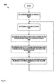
- one or more of the sensor nodes 102 of the system 100 implement a method 400 of operating in which, in 402, the sensor node determines if there is any power available to the sensor node. If there is any power available to the sensor node 102, then the sensor node determines if there is enough power available to the sensor node to permit the sensor node to execute at least one operation in 404.
- the sensor node 102 gets a listing of the possible operations given the amount of available power in 406.
- the sensor node 102 then gets a listing of the current and next operational states for the sensor node in 408.
- the sensor node 102 determines if the next operational states of the sensor node are included in the possible operations given the amount of available power in 410. If the next operational states of the sensor node 102 are included in the possible operations given the amount of available power, then the sensor node executes the next operational states that are possible to execute given the amount of available power in 412.
- one or more of the sensor nodes 102 of the system 100 implement a method 500 of operating in which, in 502, the sensor node determines if there is any power available to the sensor node. If there is any power available to the sensor node 102, then the sensor node determines if there is enough power available to the sensor node to permit the sensor node to execute at least one operation in 504.
- the sensor node 102 gets a listing of the possible operations given the amount of available power in 506.
- the sensor node 102 then gets a listing of the current and next operational states for the sensor node in 508.
- the sensor node 102 determines if the next operational states of the sensor node are included in the possible operations given the amount of available power in 510. If the next operational states of the sensor node 102 are included in the possible operations given the amount of available power, then the sensor node executes the next operational states, based upon their pre-determined priority, that are possible to execute given the amount of available power in 512.
- one factor used to weigh the priority of the next operational state is based on power usage.
- power usage is defined as (Power In - Power Out ) divided by (Energy Inertia).
- Power In is the power available from the power supply.
- Power Out is the power used by the sensor node for operations such as, for example, sensing an operating condition or communicating the sensed operating condition through the communication network.
- Energy Inertia is a factor indicating how much energy is required to change from one operation to another.
- an exemplary embodiment of a system 600 for monitoring an aircraft is substantially identical in design and operation as the system 100 with the addition of a power dispenser and conditioner 602 that is operably coupled to a source of raw power 604, a power manager 606, and a power allocator 608.
- the source of raw power 608 may include one or more of the power supplies 102a of one or more of the sensor nodes 102.
- the power dispenser and conditioner 602 is adapted to receive time varying raw power, P(t) raw , from the source of raw power 604, condition the raw power, and then transmit time varying available power, P(t) svail , to the power allocator 608.
- the power dispenser and conditioner 602 includes one or more elements for conditioning the raw power such as, for example, a rectifier, a filter, and a voltage regulator.
- the power manager 606 includes a power monitor 606a and a power controller 606b,
- the power monitor 606a is operably coupled to the output of the power dispenser and conditioner 602 for monitoring the available power, P(t) avail .
- the power monitor 606a is also operably coupled to the power controller 606b for communicating the available power, P(t) avail , to the power controller.
- the power controller 606b is also operably coupled to the power allocator 608 for controlling the operation of the power allocator.
- the power allocator 608 includes one or more allocators 608i that are each coupled to one or more elements of the sensor node 102 for controllably supplying power to the corresponding elements of the sensor node. In this manner, the power manager 606 and the power allocator 608 collectively determine the power available to the sensor node 102 and then allocate the available power to the elements of the sensor node.
- the system 600 may implement one or more aspects of the methods 400 and 500, described and illustrated above with reference to Figs. 4a , 4b , 5a , and 5b .
- the elements and functionality of the power dispenser and conditioner 602, the raw power source 604, the power manager 606, and the power allocator 608 may be provided within one or more of the sensor nodes 102 and/or provided within the central controller 104.
- an exemplary embodiment of a system 700 for monitoring an aircraft is substantially identical in design and operation as the system 600 except that the power allocator 608 is omitted and the functionality formerly provided by the power allocator is provided by the micro-controller 102d within the sensor nodes 102.
- the power controller 606b is operably coupled to the micro-controller 102d of the sensor node 102 for directing the allocation of the available power by the micro-controller to the elements of the sensor node.
- the system 700 may implement one or more aspects of the methods 400 and 500, described and illustrated above with reference to Figs. 4a , 4b , 5a , and 5b .
- the elements and functionality of the power dispenser and conditioner 602, the raw power source 604, and the power manager 606 may be provided within one or more of the sensor nodes 102 and/or provided within the central controller 104.
- one or more of the systems 100, 600, and 700 may implement a method 800 of operating in which, in 802, the sensor nodes 102 are placed into a default mode of operation which may, for example, include a sleep mode in which the sensor node is inactive, a fully active mode in which the sensor node is fully active, or one or more intermediate active modes in which the sensor node has functionality that is less than in the fully active mode.
- the system, 100, 600, or 700 will then determine the amount of power available to the system.
- the system, 100, 600, or 700 will then determine the available operational states of the sensor nodes 102 of the system given the amount of power available to the system.
- the system, 100, 600, or 700 will then determine the quality of the possible monitoring of the aircraft 108 given the available operational states of the sensor nodes 102 of the system given the amount of power available to the system.
- the quality of the possible monitoring of the aircraft 108 may be a function of what monitoring is adequate based upon the operating envelope and actual operating condition of the aircraft. For example, when the aircraft 108 is cruising at high altitudes with minimal turbulence, the level of detail and sampling rate in the monitored conditions may be less than when the aircraft is climbing to, or diving from, altitude with heavy turbulence.
- the system, 100, 600, or 700 will then modify the operational states of the sensor nodes 102 in order to optimize one or more of: 1) the available operational states of the sensor nodes, 2) the volume of data collected by the sensor nodes, 3) the sampling rate of the data collected by the sensor nodes, 4) the communication throughput of data within the network 106, and/or 5) the quality of the possible monitoring.
- the switches, 102c, 102g and 102h may be operated by the micro-controller 102d to place the sensor node 102 in a sleep mode by not permitting operation of the communication link 102b and the sensor 102f. In this manner, the use of power by the sensor node 102 is minimized.
- the sensor node 102 may be operated in a sleep mode of operation that may, for example, include a range of sleeping mode that may vary from a deep sleep to a light sleep.
- a sleep mode of operation the sensor node 102 may be completely asleep and then may be awakened by a watch dog timer, or other alert.
- a light sleep mode of operation some of the functionality of the sensor node 102 may be reduced.
- the functionality of the sensor node 102 will range from a standby mode, to a light sleep, to a deep sleep.
- one or more of the elements and functionality of the power dispenser and conditioner 602, the raw power source 604, the power manager 606, and the power allocator 608 may be provided within a sensor node 102, within one or more groups of sensor nodes, and/or within the central controller 104.
- one or more of the elements and functionality of the raw power source 604 may be provided within a single sensor node 102, within one or more groups of sensor nodes, or by all of the sensor nodes.
- the power supply 102a in each of the sensor nodes 102 within one of the systems, 100, 600 or 700 is a solar cell, then the level of solar energy at each sensor node 102 will vary as a function of its location on the aircraft 108.
- the allocation of power within the sensor nodes 102 of the systems, 100, 600 and 700 will determine the mapping of the power generated by the sensor nodes and then allocate power among the sensor nodes in order to optimize the operation of the systems in monitoring the aircraft 108.
- one or more of the sensor nodes 102 may provide one or more of the elements and functionality of the central controller 104.
- one or more of the systems 100, 600 and 700 may be operated to provide an optimal quality of the possible monitoring of the aircraft 108 by placing one or more determined sensor nodes 102 into a sleep mode, even in the presence of adequate power to operate the determined sensor nodes if the systems determine that the optimal quality of the possible monitoring of the aircraft can still be achieved.
- the determined sensor nodes 102 placed into a sleep mode may do one or more of: store power or store data within the determined sensor node.
- data may be warehoused within a sensor node 102 for later use and/or power may be stored within the sensor node for later use.
- one or more of the systems 100, 600 and 700 may be operated to place one or more determined sensor nodes 102 into a sleep mode if the data for the determined sensor node may be extrapolated using the data available for adjacent sensor nodes.
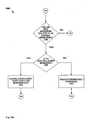
- one or more of the sensor nodes 102 of the system 100 implement a method 900 of operating in which, in 902, the sensor node determines if there is any power available to the sensor node. If there is any power available to the sensor node 102, then the sensor node determines if the power available to the sensor node is increasing or decreasing in 904.
- the sensor node 102 gets a listing of the possible operations given the amount of available power in 906. The sensor node 102 then gets a listing of the current and next operational states for the sensor node in 908.
- the sensor node 102 determines if the next operational states of the sensor node are included in the possible operations given the amount of available power in 910. If the next operational states of the sensor node 102 are included in the possible operations given the amount of available power, then the sensor node executes the next operational states that are possible to execute given the amount of available power in 912.
- the sensor node 102 discontinues operations in 914.
- one or more of the sensor nodes 102 of the system 100 implement a method 1000 of operating in which, in 1002, the sensor node determines if there is any power available to the sensor node. If there is any power available to the sensor node 102, then the sensor node gets a listing of the possible operations given the amount of available power in 1004. The sensor node 102 then gets a listing of the current and next operational states for the sensor node in 1006.
- the sensor node 102 determines if the next operational states of the sensor node are included in the possible operations given the amount of available power in 1008. If the next operational states of the sensor node 102 are included in the possible operations given the amount of available power, then the sensor node determines if the power available to the sensor node is increasing or decreasing in 1010.
- the sensor node executes the next operational states that are possible at an increased rate of execution in 1012.
- the operational states that may be executed at an increased rate of execution in 1012 may, for example, includes a sampling rate of data and/or a communication rate of data by the sensor node 102.
- the sensor node executes the next operational states that are possible at a baseline rate of execution in 1014.
- the sensor node may decrease the rate of execution.
- one or more of the sensor nodes 102 of the system 100 implement a method 1100 of operating in which, in 1102, the sensor node determines if there is any power available to the sensor node. If there is any power available to the sensor node 102, then the sensor node gets a listing of the possible operations given the amount of available power in 1104. The sensor node 102 then gets a listing of the current and next operational states for the sensor node in 1106.
- the sensor node 102 determines if the next operational states of the sensor node are included in the possible operations given the amount of available power in 1108. If the next operational states of the sensor node 102 are included in the possible operations given the amount of available power, then the sensor node determines if the power available to the sensor node is increasing or decreasing in 1110.
- the sensor node executes the next operational states that are possible in parallel in 1112. Alternatively, if the power available to the sensor node 102 is not increasing, then the sensor node executes the next operational states that are possible in series in 1114.
Landscapes
- Physics & Mathematics (AREA)
- General Physics & Mathematics (AREA)
- Engineering & Computer Science (AREA)
- Automation & Control Theory (AREA)
- Arrangements For Transmission Of Measured Signals (AREA)
- Testing Or Calibration Of Command Recording Devices (AREA)
- Air Conditioning Control Device (AREA)
Abstract
Description
- This application is related to
U.S. patent application no. 12/365,687, filed on February 4, 2009 - This disclosure relates to monitoring systems for aircraft.
-
Fig. 1 is an illustration of an exemplary embodiment of an aircraft monitoring system. -
Fig. 2 is a schematic illustration of the aircraft monitoring system ofFig. 1 . -
Fig. 3 is a schematic illustration of an exemplary embodiment of sensor nodes of the aircraft monitoring system ofFig. 2 . -
Figs. 4a and4b are flow chart illustrations of an exemplary embodiment of a method of operating the sensor nodes ofFig. 3 . -
Figs. 5a and5b are flow chart illustrations of an exemplary embodiment of a method of operating the sensor nodes ofFig. 3 . -
Fig. 6 is a schematic illustration of an exemplary embodiment of an aircraft monitoring system. -
Fig. 7 is a schematic illustration of an exemplary embodiment of an aircraft monitoring system. -
Fig. 8 is a flow chart illustration of a method of operating an aircraft monitoring system. -
Figs. 9a and9b are flow chart illustrations of an exemplary embodiment of a method of operating the sensor nodes ofFig. 3 . -
Figs. 10a and10b are flow chart illustrations of an exemplary embodiment of a method of operating the sensor nodes ofFig. 3 . -
Figs. 11a and11b are flow chart illustrations of an exemplary embodiment of a method of operating the sensor nodes ofFig. 3 . - In the drawings and description that follows, like parts are marked throughout the specification and drawings with the same reference numerals, respectively. The drawings are not necessarily to scale. Certain features of the invention may be shown exaggerated in scale or in somewhat schematic form and some details of conventional elements may not be shown in the interest of clarity and conciseness. The present invention is susceptible to embodiments of different forms. Specific embodiments are described in detail and are shown in the drawings, with the understanding that the present disclosure is to be considered an exemplification of the principles of the invention, and is not intended to limit the invention to that illustrated and described herein. It is to be fully recognized that the different teachings of the embodiments discussed below may be employed separately or in any suitable combination to produce desired results. The various characteristics mentioned above, as well as other features and characteristics described in more detail below, will be readily apparent to those skilled in the art upon reading the following detailed description of the embodiments, and by referring to the accompanying drawings.
- Referring to
Figs. 1-3 , an exemplary embodiment of asystem 100 for monitoring an aircraft includes one ormore sensors nodes 102 that are operably coupled to acentral controller 104 by anetwork 106. In an exemplary embodiment, thesensor nodes 102 are distributed within anaircraft 108 for monitoring one or more operational states of the aircraft that may, for example, include stresses, strains, temperatures, and pressures. In an exemplary embodiment, one or more of thesensor nodes 102 communicate the operational states of theaircraft 108 to thecentral controller 106 that is housed within the aircraft using, for example, anetwork 106 that may, for example, include a hard wired, fiber optic, infra red, radio frequency, acoustic, or other communication pathway. - In an exemplary embodiment, each
sensor node 102 includes apower supply 102a that is adapted to scavange energy from the immediate environment. In an exemplary embodiment, thepower supply 102a may, for example, scavenge electromagnetic energy, vibrational energy, heat energy, and/or wind energy from the immediate environment. In an exemplary embodiment, thepower supply 102a is operably coupled, and supplies power, to acommunication link 102b, aswitch 102c, a micro-controller 102d, asignal conditioner 102e, asensor 102f, a switch 102g, and aswitch 102h. - In an exemplary embodiment, the
communication link 102b is also operably coupled to theswitch 102c and adapted to transmit and receive communication signals between thesensor node 102 and thenetwork 106. In this manner, thesensor node 102 may communicate with other sensor nodes and thecentral controller 104. - In an exemplary embodiment, the
switch 102c is also operably coupled to thecommunication link 102b and the micro-controller 102d and adapted to be controlled by the micro-controller to thereby communications between the communication link and the micro-controller. In this manner, in the event that the micro-controller 102d determines that communication should not occur between thecommunication link 102b and the micro-controller such as, for example, if thesensor node 102 lacks sufficient power, the micro-controller may operate the switch to prevent communication between the communication link and the micro-controller, In an exemplary embodiment, theswitch 102c may, for example, be a mechanical, electrical, or a logical switch. - In an exemplary embodiment, the micro-controller 102d is also operably coupled to the
communication link 102b, theswitch 102c, thesignal conditioner 102e, thesensor 102f, and the switch 102g for monitoring and controlling the operation of each. In an exemplary embodiment, the micro-controller 102d may include, for example, a conventional general purpose programmable controller. - In an exemplary embodiment, the
signal conditioner 102e is also operably coupled to the micro-controller 102d and thesensor 102 and adapted to condition signals transmitted by the sensor before they are further processed by the micro-controller. In an exemplary embodiment, thesignal conditioner 102e may, for example, include one or more conventional signal processing elements such as, for example, filters, amplifiers, and analog to digital converters. - In an exemplary embodiment, the
sensor 102f is also operably coupled to thesignal conditioner 102e and the switch 102g and adapted to sense one or more operating conditions of theaircraft 108 in the immediate environment. In an exemplary embodiment, thesensor 102f may include, for example, one or more of the following: a strain gauge, a stress sensor, a temperature gauge, a pressure gauge, a radiation detector, a radar detector, a chemical detector, a corrosion detector, and/or a detector of electromagnetic energy. - In an exemplary embodiment, the switch 102g is also operably coupled to the micro-controller 102d and the
sensor 102f and adapted to control the operation of the sensor under the controller of the micro-controller. In this manner, in the event that the micro-controller 102d determines that thesensor 102f should not operate such as, for example, if thesensor node 102 lacks sufficient power, the micro-controller may operate the switch 102g to prevent power from being supplied by thepower supply 102a to the sensor. - In an exemplary embodiment, the
switch 102h is also operably coupled to the micro-controller 102d and thecommunication link 102b and adapted to control the operation of the communication link under the controlled of the micro-controller. In this manner, in the event that the micro-controller 102d determines that thecommunication link 102b should not operate such as, for example, if thesensor node 102 lacks sufficient power, the micro-controller may operate theswitch 102h to prevent power from being supplied by thepower supply 102a to the communication link. - Referring now to
Figs. 4a and4b , in an exemplary embodiment, one or more of thesensor nodes 102 of thesystem 100 implement amethod 400 of operating in which, in 402, the sensor node determines if there is any power available to the sensor node. If there is any power available to thesensor node 102, then the sensor node determines if there is enough power available to the sensor node to permit the sensor node to execute at least one operation in 404. - If there is enough power available to permit the
sensor node 102 to execute at least one operation, then the sensor node gets a listing of the possible operations given the amount of available power in 406. Thesensor node 102 then gets a listing of the current and next operational states for the sensor node in 408. - The
sensor node 102 then determines if the next operational states of the sensor node are included in the possible operations given the amount of available power in 410. If the next operational states of thesensor node 102 are included in the possible operations given the amount of available power, then the sensor node executes the next operational states that are possible to execute given the amount of available power in 412. - Referring now to
Figs. 5a and5b , in an exemplary embodiment, one or more of thesensor nodes 102 of thesystem 100 implement amethod 500 of operating in which, in 502, the sensor node determines if there is any power available to the sensor node. If there is any power available to thesensor node 102, then the sensor node determines if there is enough power available to the sensor node to permit the sensor node to execute at least one operation in 504. - If there is enough power available to permit the
sensor node 102 to execute at least one operation, then the sensor gets a listing of the possible operations given the amount of available power in 506. Thesensor node 102 then gets a listing of the current and next operational states for the sensor node in 508. - The
sensor node 102 then determines if the next operational states of the sensor node are included in the possible operations given the amount of available power in 510. If the next operational states of thesensor node 102 are included in the possible operations given the amount of available power, then the sensor node executes the next operational states, based upon their pre-determined priority, that are possible to execute given the amount of available power in 512. - In an exemplary embodiment, one factor used to weigh the priority of the next operational state is based on power usage. In this embodiment, power usage is defined as (PowerIn - PowerOut) divided by (Energy Inertia). PowerIn is the power available from the power supply. PowerOut is the power used by the sensor node for operations such as, for example, sensing an operating condition or communicating the sensed operating condition through the communication network. Energy Inertia is a factor indicating how much energy is required to change from one operation to another.
- Referring now to
Fig. 6 , an exemplary embodiment of asystem 600 for monitoring an aircraft is substantially identical in design and operation as thesystem 100 with the addition of a power dispenser andconditioner 602 that is operably coupled to a source ofraw power 604, apower manager 606, and apower allocator 608. - In an exemplary embodiment, the source of
raw power 608 may include one or more of thepower supplies 102a of one or more of thesensor nodes 102. In an exemplary embodiment, the power dispenser andconditioner 602 is adapted to receive time varying raw power, P(t)raw, from the source ofraw power 604, condition the raw power, and then transmit time varying available power, P(t)svail, to thepower allocator 608. In an exemplary embodiment, the power dispenser andconditioner 602 includes one or more elements for conditioning the raw power such as, for example, a rectifier, a filter, and a voltage regulator. - In an exemplary embodiment, the
power manager 606 includes apower monitor 606a and apower controller 606b, In an exemplary embodiment, thepower monitor 606a is operably coupled to the output of the power dispenser andconditioner 602 for monitoring the available power, P(t)avail. In an exemplary embodiment, thepower monitor 606a is also operably coupled to thepower controller 606b for communicating the available power, P(t)avail, to the power controller. In an exemplary embodiment, thepower controller 606b is also operably coupled to thepower allocator 608 for controlling the operation of the power allocator. - In an exemplary embodiment, the
power allocator 608 includes one or more allocators 608i that are each coupled to one or more elements of thesensor node 102 for controllably supplying power to the corresponding elements of the sensor node. In this manner, thepower manager 606 and thepower allocator 608 collectively determine the power available to thesensor node 102 and then allocate the available power to the elements of the sensor node. - In an exemplary embodiment, the
system 600 may implement one or more aspects of themethods Figs. 4a ,4b ,5a , and5b . In an exemplary embodiment, the elements and functionality of the power dispenser andconditioner 602, theraw power source 604, thepower manager 606, and thepower allocator 608 may be provided within one or more of thesensor nodes 102 and/or provided within thecentral controller 104. - Referring now to
Fig. 7 , an exemplary embodiment of asystem 700 for monitoring an aircraft is substantially identical in design and operation as thesystem 600 except that thepower allocator 608 is omitted and the functionality formerly provided by the power allocator is provided by themicro-controller 102d within thesensor nodes 102. - In particular, in the
system 700, thepower controller 606b is operably coupled to themicro-controller 102d of thesensor node 102 for directing the allocation of the available power by the micro-controller to the elements of the sensor node. - In an exemplary embodiment, the
system 700 may implement one or more aspects of themethods Figs. 4a ,4b ,5a , and5b . In an exemplary embodiment, the elements and functionality of the power dispenser andconditioner 602, theraw power source 604, and thepower manager 606 may be provided within one or more of thesensor nodes 102 and/or provided within thecentral controller 104. - Referring now to
Fig. 8 , in an exemplary embodiment, one or more of thesystems method 800 of operating in which, in 802, thesensor nodes 102 are placed into a default mode of operation which may, for example, include a sleep mode in which the sensor node is inactive, a fully active mode in which the sensor node is fully active, or one or more intermediate active modes in which the sensor node has functionality that is less than in the fully active mode. In 804, the system, 100, 600, or 700, will then determine the amount of power available to the system. In an exemplary embodiment, in 806, the system, 100, 600, or 700, will then determine the available operational states of thesensor nodes 102 of the system given the amount of power available to the system. - In an exemplary embodiment, in 808, the system, 100, 600, or 700, will then determine the quality of the possible monitoring of the
aircraft 108 given the available operational states of thesensor nodes 102 of the system given the amount of power available to the system. In an exemplary embodiment, the quality of the possible monitoring of theaircraft 108 may be a function of what monitoring is adequate based upon the operating envelope and actual operating condition of the aircraft. For example, when theaircraft 108 is cruising at high altitudes with minimal turbulence, the level of detail and sampling rate in the monitored conditions may be less than when the aircraft is climbing to, or diving from, altitude with heavy turbulence. - In an exemplary embodiment, in 810, the system, 100, 600, or 700, will then modify the operational states of the
sensor nodes 102 in order to optimize one or more of: 1) the available operational states of the sensor nodes, 2) the volume of data collected by the sensor nodes, 3) the sampling rate of the data collected by the sensor nodes, 4) the communication throughput of data within thenetwork 106, and/or 5) the quality of the possible monitoring. - In an exemplary embodiment, during the operation of the systems, 100, 600 and/or 700, the switches, 102c, 102g and 102h, may be operated by the
micro-controller 102d to place thesensor node 102 in a sleep mode by not permitting operation of thecommunication link 102b and thesensor 102f. In this manner, the use of power by thesensor node 102 is minimized. - In an exemplary embodiment, during the operation of the systems, 100, 600 and/or 700, the
sensor node 102 may be operated in a sleep mode of operation that may, for example, include a range of sleeping mode that may vary from a deep sleep to a light sleep. In an exemplary embodiment, in a deep sleep mode of operation, thesensor node 102 may be completely asleep and then may be awakened by a watch dog timer, or other alert. In an exemplary embodiment, in a light sleep mode of operation, some of the functionality of thesensor node 102 may be reduced. In an exemplary embodiment, in one or more intermediate sleeping modes of operation, the functionality of thesensor node 102 will range from a standby mode, to a light sleep, to a deep sleep. - In an exemplary embodiment, in one or more of the
systems conditioner 602, theraw power source 604, thepower manager 606, and thepower allocator 608 may be provided within asensor node 102, within one or more groups of sensor nodes, and/or within thecentral controller 104. - In an exemplary embodiment, in one or more of the systems, 100, 600 and 700, one or more of the elements and functionality of the
raw power source 604 may be provided within asingle sensor node 102, within one or more groups of sensor nodes, or by all of the sensor nodes. For example, if thepower supply 102a in each of thesensor nodes 102 within one of the systems, 100, 600 or 700, is a solar cell, then the level of solar energy at eachsensor node 102 will vary as a function of its location on theaircraft 108. In an exemplary embodiment, the allocation of power within thesensor nodes 102 of the systems, 100, 600 and 700, will determine the mapping of the power generated by the sensor nodes and then allocate power among the sensor nodes in order to optimize the operation of the systems in monitoring theaircraft 108. - In an exemplary embodiment, in one or more of the
systems sensor nodes 102 may provide one or more of the elements and functionality of thecentral controller 104. - In an exemplary embodiment, one or more of the
systems aircraft 108 by placing one or moredetermined sensor nodes 102 into a sleep mode, even in the presence of adequate power to operate the determined sensor nodes if the systems determine that the optimal quality of the possible monitoring of the aircraft can still be achieved. In this manner, thedetermined sensor nodes 102 placed into a sleep mode may do one or more of: store power or store data within the determined sensor node. In this manner, data may be warehoused within asensor node 102 for later use and/or power may be stored within the sensor node for later use. - In an exemplary embodiment, one or more of the
systems determined sensor nodes 102 into a sleep mode if the data for the determined sensor node may be extrapolated using the data available for adjacent sensor nodes. - Referring now to
Figs. 9a and9b , in an exemplary embodiment, one or more of thesensor nodes 102 of thesystem 100 implement amethod 900 of operating in which, in 902, the sensor node determines if there is any power available to the sensor node. If there is any power available to thesensor node 102, then the sensor node determines if the power available to the sensor node is increasing or decreasing in 904. - If the power available to the
sensor node 102 is increasing, then the sensor node gets a listing of the possible operations given the amount of available power in 906. Thesensor node 102 then gets a listing of the current and next operational states for the sensor node in 908. - The
sensor node 102 then determines if the next operational states of the sensor node are included in the possible operations given the amount of available power in 910. If the next operational states of thesensor node 102 are included in the possible operations given the amount of available power, then the sensor node executes the next operational states that are possible to execute given the amount of available power in 912. - Alternatively, if the power available to the
sensor node 102 is not increasing, or is increasing at a rate below a predetermined value, then the sensor node discontinues operations in 914. - Referring now to
Figs. 10a and10b , in an exemplary embodiment, one or more of thesensor nodes 102 of thesystem 100 implement amethod 1000 of operating in which, in 1002, the sensor node determines if there is any power available to the sensor node. If there is any power available to thesensor node 102, then the sensor node gets a listing of the possible operations given the amount of available power in 1004. Thesensor node 102 then gets a listing of the current and next operational states for the sensor node in 1006. - The
sensor node 102 then determines if the next operational states of the sensor node are included in the possible operations given the amount of available power in 1008. If the next operational states of thesensor node 102 are included in the possible operations given the amount of available power, then the sensor node determines if the power available to the sensor node is increasing or decreasing in 1010. - If the power available to the
sensor node 102 is increasing, then the sensor node executes the next operational states that are possible at an increased rate of execution in 1012. In an exemplary embodiment, the operational states that may be executed at an increased rate of execution in 1012 may, for example, includes a sampling rate of data and/or a communication rate of data by thesensor node 102. - Alternatively, if the power available to the
sensor node 102 is not increasing, then the sensor node executes the next operational states that are possible at a baseline rate of execution in 1014. In an exemplary embodiment, if the power available to the sensor node is not increasing, or is increasing at a rate below a predetermined minimum rate, the sensor node may decrease the rate of execution. - Referring now to
Figs. 11a and11b , in an exemplary embodiment, one or more of thesensor nodes 102 of thesystem 100 implement amethod 1100 of operating in which, in 1102, the sensor node determines if there is any power available to the sensor node. If there is any power available to thesensor node 102, then the sensor node gets a listing of the possible operations given the amount of available power in 1104. Thesensor node 102 then gets a listing of the current and next operational states for the sensor node in 1106. - The
sensor node 102 then determines if the next operational states of the sensor node are included in the possible operations given the amount of available power in 1108. If the next operational states of thesensor node 102 are included in the possible operations given the amount of available power, then the sensor node determines if the power available to the sensor node is increasing or decreasing in 1110. - If the power available to the
sensor node 102 is increasing, then the sensor node executes the next operational states that are possible in parallel in 1112. Alternatively, if the power available to thesensor node 102 is not increasing, then the sensor node executes the next operational states that are possible in series in 1114. - It is understood that variations may be made in the above without departing from the scope of the invention. While specific embodiments have been shown and described, modifications can be made by one skilled in the art without departing from the spirit or teaching of this invention. The embodiments as described are exemplary only and are not limiting. One or more elements of the exemplary embodiments may be combined, in whole or in part, with one or more elements of one or more of the other exemplary embodiments. Many variations and modifications are possible and are within the scope of the invention. Accordingly, the scope of protection is not limited to the embodiments described, but is only limited by the claims that follow, the scope of which shall include all equivalents of the subject matter of the claims.
Claims (7)
- A method of operating a system for monitoring one or more operating conditions of a structure, comprising:providing power at sensors positioned around the structure;determining if the power provided to one or more of the sensors is increasing; andcontrolling the operation of the sensors as a function of whether or not the power provided to one or more of the sensors in increasing.
- The method of claim 1, further comprising one or more of the sensors executing one or more operations if the amount of available power to the one or more sensors is increasing.
- The method of claim or claim 2, further comprising one or more of the sensors executing one or more operations at an increased rate of execution if the amount of available power to the one or more of the sensors is increasing.
- The method of any one of the preceding claims, further comprising one or more of the sensors executing a plurality of operations in parallel if the amount of available power to the one or more sensors is increasing.
- The method of any one of the preceding claims, further comprising one or more of the sensors discontinuing execution of operations if the amount of available power to the one or more sensors is not increasing.
- The method of any one of the preceding claims, further comprising one or more of the sensors executing one or more operations at a baseline rate of execution if the amount of available power to the one or more sensors is not increasing.
- The method of any one of the preceding claims, further comprising one or more of the sensors executing operations in series if the amount of available power to the one or more sensors is not increasing.
Applications Claiming Priority (1)
| Application Number | Priority Date | Filing Date | Title |
|---|---|---|---|
| US12/365,687 US8294597B2 (en) | 2009-02-04 | 2009-02-04 | Self regulating power conditioner for energy harvesting applications |
Publications (3)
| Publication Number | Publication Date |
|---|---|
| EP2221700A2 true EP2221700A2 (en) | 2010-08-25 |
| EP2221700A3 EP2221700A3 (en) | 2013-10-23 |
| EP2221700B1 EP2221700B1 (en) | 2018-04-11 |
Family
ID=42232907
Family Applications (1)
| Application Number | Title | Priority Date | Filing Date |
|---|---|---|---|
| EP10152515.2A Active EP2221700B1 (en) | 2009-02-04 | 2010-02-03 | Self Regulating Power Conditioner for Energy Harvesting Applications |
Country Status (2)
| Country | Link |
|---|---|
| US (1) | US8294597B2 (en) |
| EP (1) | EP2221700B1 (en) |
Family Cites Families (7)
| Publication number | Priority date | Publication date | Assignee | Title |
|---|---|---|---|---|
| GB2303979B (en) * | 1995-08-02 | 2000-03-29 | Mitsubishi Electric Corp | A control system and control method for uninterruptible power supply |
| US6816758B2 (en) * | 2001-04-26 | 2004-11-09 | The Boeing Company | Programmable controller for remotely controlling input power through a switch to a load and an associated method of operation |
| JP3671891B2 (en) * | 2001-10-04 | 2005-07-13 | オムロン株式会社 | Sensor network system management method, sensor network system management program, recording medium storing sensor network system management program, and sensor network system management apparatus |
| US7573396B2 (en) * | 2004-09-21 | 2009-08-11 | Saf-T-Glo Limited | Air craft emergency lighting system |
| US8073554B2 (en) * | 2006-12-20 | 2011-12-06 | Nortel Networks Limited | System and method for providing power management in a sensor network |
| US7849344B2 (en) * | 2007-07-20 | 2010-12-07 | International Business Machines Corporation | Method for improving accuracy in providing information pertaining to battery power capacity |
| US8098143B2 (en) * | 2008-12-10 | 2012-01-17 | Lockheed Martin Corporation | Power aware techniques for energy harvesting remote sensor system |
-
2009
- 2009-02-04 US US12/365,687 patent/US8294597B2/en active Active
-
2010
- 2010-02-03 EP EP10152515.2A patent/EP2221700B1/en active Active
Non-Patent Citations (1)
| Title |
|---|
| None |
Also Published As
| Publication number | Publication date |
|---|---|
| US20100194600A1 (en) | 2010-08-05 |
| EP2221700A3 (en) | 2013-10-23 |
| EP2221700B1 (en) | 2018-04-11 |
| US8294597B2 (en) | 2012-10-23 |
Similar Documents
| Publication | Publication Date | Title |
|---|---|---|
| EP2197151A1 (en) | Power aware techniques for energy harvesting remote sensor systems | |
| JP7075014B2 (en) | Field device | |
| US20190101879A1 (en) | Power Aware Techniques For Energy Harvesting Remote Sensor Systems | |
| US9621371B2 (en) | Wireless sensor device with wireless remote programming | |
| CN103982939A (en) | Heating energy-saving control method and device based on human body induction | |
| EP3396812B1 (en) | Battery management device, battery management system, and battery management method | |
| JP2009064438A (en) | Process monitoring system, process monitoring method, and data transmission method | |
| EP2840453B1 (en) | Communication system containing field devices and method for controlling the system | |
| JP5915627B2 (en) | Process control system | |
| CN103003773A (en) | A method in a wireless process control system for reducing power consumption, and a controller and computer program products | |
| GB2602022A (en) | Determining a status of a tyre monitoring device | |
| EP2219386B1 (en) | Power free remote sensor system data transmission | |
| EP2221700B1 (en) | Self Regulating Power Conditioner for Energy Harvesting Applications | |
| EP3416431B1 (en) | Battery use management for wireless networks | |
| CN103327581A (en) | Communication method and device for greenhouse wireless monitoring | |
| EP2219385B1 (en) | Methods for anti-collision and multiple access in rfid communications | |
| CN204479974U (en) | A kind of heating equipment controller | |
| JP2021026743A (en) | Wireless sensor device, sensor information collection system, and sensor information collection method | |
| KR20230072896A (en) | United management system for monitoring device and method for operating for the same | |
| KR20120009906A (en) | Production control method considering supply and demand in smart industry and system that performs it |
Legal Events
| Date | Code | Title | Description |
|---|---|---|---|
| PUAI | Public reference made under article 153(3) epc to a published international application that has entered the european phase |
Free format text: ORIGINAL CODE: 0009012 |
|
| AK | Designated contracting states |
Kind code of ref document: A2 Designated state(s): AT BE BG CH CY CZ DE DK EE ES FI FR GB GR HR HU IE IS IT LI LT LU LV MC MK MT NL NO PL PT RO SE SI SK SM TR |
|
| AX | Request for extension of the european patent |
Extension state: AL BA RS |
|
| PUAL | Search report despatched |
Free format text: ORIGINAL CODE: 0009013 |
|
| AK | Designated contracting states |
Kind code of ref document: A3 Designated state(s): AT BE BG CH CY CZ DE DK EE ES FI FR GB GR HR HU IE IS IT LI LT LU LV MC MK MT NL NO PL PT RO SE SI SK SM TR |
|
| AX | Request for extension of the european patent |
Extension state: AL BA RS |
|
| RIC1 | Information provided on ipc code assigned before grant |
Ipc: G05B 9/02 20060101ALI20130913BHEP Ipc: G05B 23/02 20060101AFI20130913BHEP |
|
| 17P | Request for examination filed |
Effective date: 20140124 |
|
| 17Q | First examination report despatched |
Effective date: 20150625 |
|
| STAA | Information on the status of an ep patent application or granted ep patent |
Free format text: STATUS: EXAMINATION IS IN PROGRESS |
|
| GRAP | Despatch of communication of intention to grant a patent |
Free format text: ORIGINAL CODE: EPIDOSNIGR1 |
|
| STAA | Information on the status of an ep patent application or granted ep patent |
Free format text: STATUS: GRANT OF PATENT IS INTENDED |
|
| INTG | Intention to grant announced |
Effective date: 20180115 |
|
| GRAS | Grant fee paid |
Free format text: ORIGINAL CODE: EPIDOSNIGR3 |
|
| GRAA | (expected) grant |
Free format text: ORIGINAL CODE: 0009210 |
|
| STAA | Information on the status of an ep patent application or granted ep patent |
Free format text: STATUS: THE PATENT HAS BEEN GRANTED |
|
| AK | Designated contracting states |
Kind code of ref document: B1 Designated state(s): AT BE BG CH CY CZ DE DK EE ES FI FR GB GR HR HU IE IS IT LI LT LU LV MC MK MT NL NO PL PT RO SE SI SK SM TR |
|
| REG | Reference to a national code |
Ref country code: GB Ref legal event code: FG4D |
|
| REG | Reference to a national code |
Ref country code: CH Ref legal event code: EP |
|
| REG | Reference to a national code |
Ref country code: AT Ref legal event code: REF Ref document number: 988685 Country of ref document: AT Kind code of ref document: T Effective date: 20180415 |
|
| REG | Reference to a national code |
Ref country code: IE Ref legal event code: FG4D |
|
| REG | Reference to a national code |
Ref country code: DE Ref legal event code: R096 Ref document number: 602010049787 Country of ref document: DE |
|
| REG | Reference to a national code |
Ref country code: NL Ref legal event code: MP Effective date: 20180411 |
|
| REG | Reference to a national code |
Ref country code: LT Ref legal event code: MG4D |
|
| PG25 | Lapsed in a contracting state [announced via postgrant information from national office to epo] |
Ref country code: NL Free format text: LAPSE BECAUSE OF FAILURE TO SUBMIT A TRANSLATION OF THE DESCRIPTION OR TO PAY THE FEE WITHIN THE PRESCRIBED TIME-LIMIT Effective date: 20180411 |
|
| PG25 | Lapsed in a contracting state [announced via postgrant information from national office to epo] |
Ref country code: PL Free format text: LAPSE BECAUSE OF FAILURE TO SUBMIT A TRANSLATION OF THE DESCRIPTION OR TO PAY THE FEE WITHIN THE PRESCRIBED TIME-LIMIT Effective date: 20180411 Ref country code: LT Free format text: LAPSE BECAUSE OF FAILURE TO SUBMIT A TRANSLATION OF THE DESCRIPTION OR TO PAY THE FEE WITHIN THE PRESCRIBED TIME-LIMIT Effective date: 20180411 Ref country code: BG Free format text: LAPSE BECAUSE OF FAILURE TO SUBMIT A TRANSLATION OF THE DESCRIPTION OR TO PAY THE FEE WITHIN THE PRESCRIBED TIME-LIMIT Effective date: 20180711 Ref country code: FI Free format text: LAPSE BECAUSE OF FAILURE TO SUBMIT A TRANSLATION OF THE DESCRIPTION OR TO PAY THE FEE WITHIN THE PRESCRIBED TIME-LIMIT Effective date: 20180411 Ref country code: SE Free format text: LAPSE BECAUSE OF FAILURE TO SUBMIT A TRANSLATION OF THE DESCRIPTION OR TO PAY THE FEE WITHIN THE PRESCRIBED TIME-LIMIT Effective date: 20180411 Ref country code: NO Free format text: LAPSE BECAUSE OF FAILURE TO SUBMIT A TRANSLATION OF THE DESCRIPTION OR TO PAY THE FEE WITHIN THE PRESCRIBED TIME-LIMIT Effective date: 20180711 Ref country code: ES Free format text: LAPSE BECAUSE OF FAILURE TO SUBMIT A TRANSLATION OF THE DESCRIPTION OR TO PAY THE FEE WITHIN THE PRESCRIBED TIME-LIMIT Effective date: 20180411 |
|
| PG25 | Lapsed in a contracting state [announced via postgrant information from national office to epo] |
Ref country code: GR Free format text: LAPSE BECAUSE OF FAILURE TO SUBMIT A TRANSLATION OF THE DESCRIPTION OR TO PAY THE FEE WITHIN THE PRESCRIBED TIME-LIMIT Effective date: 20180712 Ref country code: HR Free format text: LAPSE BECAUSE OF FAILURE TO SUBMIT A TRANSLATION OF THE DESCRIPTION OR TO PAY THE FEE WITHIN THE PRESCRIBED TIME-LIMIT Effective date: 20180411 Ref country code: LV Free format text: LAPSE BECAUSE OF FAILURE TO SUBMIT A TRANSLATION OF THE DESCRIPTION OR TO PAY THE FEE WITHIN THE PRESCRIBED TIME-LIMIT Effective date: 20180411 |
|
| REG | Reference to a national code |
Ref country code: AT Ref legal event code: MK05 Ref document number: 988685 Country of ref document: AT Kind code of ref document: T Effective date: 20180411 |
|
| PG25 | Lapsed in a contracting state [announced via postgrant information from national office to epo] |
Ref country code: PT Free format text: LAPSE BECAUSE OF FAILURE TO SUBMIT A TRANSLATION OF THE DESCRIPTION OR TO PAY THE FEE WITHIN THE PRESCRIBED TIME-LIMIT Effective date: 20180813 |
|
| REG | Reference to a national code |
Ref country code: DE Ref legal event code: R097 Ref document number: 602010049787 Country of ref document: DE |
|
| PG25 | Lapsed in a contracting state [announced via postgrant information from national office to epo] |
Ref country code: SK Free format text: LAPSE BECAUSE OF FAILURE TO SUBMIT A TRANSLATION OF THE DESCRIPTION OR TO PAY THE FEE WITHIN THE PRESCRIBED TIME-LIMIT Effective date: 20180411 Ref country code: CZ Free format text: LAPSE BECAUSE OF FAILURE TO SUBMIT A TRANSLATION OF THE DESCRIPTION OR TO PAY THE FEE WITHIN THE PRESCRIBED TIME-LIMIT Effective date: 20180411 Ref country code: RO Free format text: LAPSE BECAUSE OF FAILURE TO SUBMIT A TRANSLATION OF THE DESCRIPTION OR TO PAY THE FEE WITHIN THE PRESCRIBED TIME-LIMIT Effective date: 20180411 Ref country code: EE Free format text: LAPSE BECAUSE OF FAILURE TO SUBMIT A TRANSLATION OF THE DESCRIPTION OR TO PAY THE FEE WITHIN THE PRESCRIBED TIME-LIMIT Effective date: 20180411 Ref country code: AT Free format text: LAPSE BECAUSE OF FAILURE TO SUBMIT A TRANSLATION OF THE DESCRIPTION OR TO PAY THE FEE WITHIN THE PRESCRIBED TIME-LIMIT Effective date: 20180411 Ref country code: DK Free format text: LAPSE BECAUSE OF FAILURE TO SUBMIT A TRANSLATION OF THE DESCRIPTION OR TO PAY THE FEE WITHIN THE PRESCRIBED TIME-LIMIT Effective date: 20180411 |
|
| PLBE | No opposition filed within time limit |
Free format text: ORIGINAL CODE: 0009261 |
|
| STAA | Information on the status of an ep patent application or granted ep patent |
Free format text: STATUS: NO OPPOSITION FILED WITHIN TIME LIMIT |
|
| PG25 | Lapsed in a contracting state [announced via postgrant information from national office to epo] |
Ref country code: SM Free format text: LAPSE BECAUSE OF FAILURE TO SUBMIT A TRANSLATION OF THE DESCRIPTION OR TO PAY THE FEE WITHIN THE PRESCRIBED TIME-LIMIT Effective date: 20180411 |
|
| 26N | No opposition filed |
Effective date: 20190114 |
|
| PG25 | Lapsed in a contracting state [announced via postgrant information from national office to epo] |
Ref country code: SI Free format text: LAPSE BECAUSE OF FAILURE TO SUBMIT A TRANSLATION OF THE DESCRIPTION OR TO PAY THE FEE WITHIN THE PRESCRIBED TIME-LIMIT Effective date: 20180411 |
|
| REG | Reference to a national code |
Ref country code: CH Ref legal event code: PL |
|
| PG25 | Lapsed in a contracting state [announced via postgrant information from national office to epo] |
Ref country code: MC Free format text: LAPSE BECAUSE OF FAILURE TO SUBMIT A TRANSLATION OF THE DESCRIPTION OR TO PAY THE FEE WITHIN THE PRESCRIBED TIME-LIMIT Effective date: 20180411 Ref country code: LU Free format text: LAPSE BECAUSE OF NON-PAYMENT OF DUE FEES Effective date: 20190203 |
|
| REG | Reference to a national code |
Ref country code: BE Ref legal event code: MM Effective date: 20190228 |
|
| REG | Reference to a national code |
Ref country code: IE Ref legal event code: MM4A |
|
| PG25 | Lapsed in a contracting state [announced via postgrant information from national office to epo] |
Ref country code: LI Free format text: LAPSE BECAUSE OF NON-PAYMENT OF DUE FEES Effective date: 20190228 Ref country code: CH Free format text: LAPSE BECAUSE OF NON-PAYMENT OF DUE FEES Effective date: 20190228 |
|
| PG25 | Lapsed in a contracting state [announced via postgrant information from national office to epo] |
Ref country code: IE Free format text: LAPSE BECAUSE OF NON-PAYMENT OF DUE FEES Effective date: 20190203 |
|
| PG25 | Lapsed in a contracting state [announced via postgrant information from national office to epo] |
Ref country code: BE Free format text: LAPSE BECAUSE OF NON-PAYMENT OF DUE FEES Effective date: 20190228 |
|
| PG25 | Lapsed in a contracting state [announced via postgrant information from national office to epo] |
Ref country code: TR Free format text: LAPSE BECAUSE OF FAILURE TO SUBMIT A TRANSLATION OF THE DESCRIPTION OR TO PAY THE FEE WITHIN THE PRESCRIBED TIME-LIMIT Effective date: 20180411 |
|
| PG25 | Lapsed in a contracting state [announced via postgrant information from national office to epo] |
Ref country code: MT Free format text: LAPSE BECAUSE OF NON-PAYMENT OF DUE FEES Effective date: 20190203 |
|
| PG25 | Lapsed in a contracting state [announced via postgrant information from national office to epo] |
Ref country code: CY Free format text: LAPSE BECAUSE OF FAILURE TO SUBMIT A TRANSLATION OF THE DESCRIPTION OR TO PAY THE FEE WITHIN THE PRESCRIBED TIME-LIMIT Effective date: 20180411 |
|
| PG25 | Lapsed in a contracting state [announced via postgrant information from national office to epo] |
Ref country code: IS Free format text: LAPSE BECAUSE OF FAILURE TO SUBMIT A TRANSLATION OF THE DESCRIPTION OR TO PAY THE FEE WITHIN THE PRESCRIBED TIME-LIMIT Effective date: 20180811 |
|
| PG25 | Lapsed in a contracting state [announced via postgrant information from national office to epo] |
Ref country code: HU Free format text: LAPSE BECAUSE OF FAILURE TO SUBMIT A TRANSLATION OF THE DESCRIPTION OR TO PAY THE FEE WITHIN THE PRESCRIBED TIME-LIMIT; INVALID AB INITIO Effective date: 20100203 |
|
| PG25 | Lapsed in a contracting state [announced via postgrant information from national office to epo] |
Ref country code: MK Free format text: LAPSE BECAUSE OF FAILURE TO SUBMIT A TRANSLATION OF THE DESCRIPTION OR TO PAY THE FEE WITHIN THE PRESCRIBED TIME-LIMIT Effective date: 20180411 |
|
| P01 | Opt-out of the competence of the unified patent court (upc) registered |
Effective date: 20230613 |
|
| PGFP | Annual fee paid to national office [announced via postgrant information from national office to epo] |
Ref country code: GB Payment date: 20260227 Year of fee payment: 17 |
|
| PGFP | Annual fee paid to national office [announced via postgrant information from national office to epo] |
Ref country code: DE Payment date: 20260227 Year of fee payment: 17 |
|
| PGFP | Annual fee paid to national office [announced via postgrant information from national office to epo] |
Ref country code: IT Payment date: 20260219 Year of fee payment: 17 |
|
| PGFP | Annual fee paid to national office [announced via postgrant information from national office to epo] |
Ref country code: FR Payment date: 20260225 Year of fee payment: 17 |