EP2221513A1 - System and method for controlling the torque transferable by a mechanical drive employing an oil-bath clutch. - Google Patents
System and method for controlling the torque transferable by a mechanical drive employing an oil-bath clutch. Download PDFInfo
- Publication number
- EP2221513A1 EP2221513A1 EP10153739A EP10153739A EP2221513A1 EP 2221513 A1 EP2221513 A1 EP 2221513A1 EP 10153739 A EP10153739 A EP 10153739A EP 10153739 A EP10153739 A EP 10153739A EP 2221513 A1 EP2221513 A1 EP 2221513A1
- Authority
- EP
- European Patent Office
- Prior art keywords
- clutch
- variable
- value
- speed drive
- torque
- Prior art date
- Legal status (The legal status is an assumption and is not a legal conclusion. Google has not performed a legal analysis and makes no representation as to the accuracy of the status listed.)
- Granted
Links
Images



Classifications
-
- F—MECHANICAL ENGINEERING; LIGHTING; HEATING; WEAPONS; BLASTING
- F16—ENGINEERING ELEMENTS AND UNITS; GENERAL MEASURES FOR PRODUCING AND MAINTAINING EFFECTIVE FUNCTIONING OF MACHINES OR INSTALLATIONS; THERMAL INSULATION IN GENERAL
- F16H—GEARING
- F16H61/00—Control functions within control units of change-speed- or reversing-gearings for conveying rotary motion ; Control of exclusively fluid gearing, friction gearing, gearings with endless flexible members or other particular types of gearing
- F16H61/66—Control functions within control units of change-speed- or reversing-gearings for conveying rotary motion ; Control of exclusively fluid gearing, friction gearing, gearings with endless flexible members or other particular types of gearing specially adapted for continuously variable gearings
- F16H61/662—Control functions within control units of change-speed- or reversing-gearings for conveying rotary motion ; Control of exclusively fluid gearing, friction gearing, gearings with endless flexible members or other particular types of gearing specially adapted for continuously variable gearings with endless flexible members
- F16H61/66272—Control functions within control units of change-speed- or reversing-gearings for conveying rotary motion ; Control of exclusively fluid gearing, friction gearing, gearings with endless flexible members or other particular types of gearing specially adapted for continuously variable gearings with endless flexible members characterised by means for controlling the torque transmitting capability of the gearing
-
- F—MECHANICAL ENGINEERING; LIGHTING; HEATING; WEAPONS; BLASTING
- F16—ENGINEERING ELEMENTS AND UNITS; GENERAL MEASURES FOR PRODUCING AND MAINTAINING EFFECTIVE FUNCTIONING OF MACHINES OR INSTALLATIONS; THERMAL INSULATION IN GENERAL
- F16H—GEARING
- F16H61/00—Control functions within control units of change-speed- or reversing-gearings for conveying rotary motion ; Control of exclusively fluid gearing, friction gearing, gearings with endless flexible members or other particular types of gearing
- F16H61/66—Control functions within control units of change-speed- or reversing-gearings for conveying rotary motion ; Control of exclusively fluid gearing, friction gearing, gearings with endless flexible members or other particular types of gearing specially adapted for continuously variable gearings
- F16H2061/6604—Special control features generally applicable to continuously variable gearings
- F16H2061/661—Conjoint control of CVT and drive clutch
-
- F—MECHANICAL ENGINEERING; LIGHTING; HEATING; WEAPONS; BLASTING
- F16—ENGINEERING ELEMENTS AND UNITS; GENERAL MEASURES FOR PRODUCING AND MAINTAINING EFFECTIVE FUNCTIONING OF MACHINES OR INSTALLATIONS; THERMAL INSULATION IN GENERAL
- F16H—GEARING
- F16H61/00—Control functions within control units of change-speed- or reversing-gearings for conveying rotary motion ; Control of exclusively fluid gearing, friction gearing, gearings with endless flexible members or other particular types of gearing
- F16H61/66—Control functions within control units of change-speed- or reversing-gearings for conveying rotary motion ; Control of exclusively fluid gearing, friction gearing, gearings with endless flexible members or other particular types of gearing specially adapted for continuously variable gearings
- F16H2061/6604—Special control features generally applicable to continuously variable gearings
- F16H2061/6618—Protecting CVTs against overload by limiting clutch capacity, e.g. torque fuse
Definitions
- the present invention relates to a system and method for controlling the torque transferable by a mechanical drive.
- the present invention may be used to particular advantage, though not exclusively, in small, i.e. low-power, work vehicles (mechanical shovels, excavators, tractors, etc.).
- a common problem of work vehicles mechanical shovels, excavators, tractors, etc.
- low-power engines are that, when moving a heavy load, of gravel for example, persistent acceleration by the driver may result in even serious damage to drive components between the engine and the drive-wheel axle.
- the main object of the present invention is therefore to provide a system and method for fully safeguarding the mechanical component parts of the mechanical drive.
- the present invention employs a clutch assembly whose release/engagement percentage can be determined and controlled electronically, and which advantageously, though not necessarily, comprises an oil-bath clutch.
- the mechanical drive considered also comprises a variable-speed drive, which advantageously, though not necessarily, comprises two pulleys connected by a chain.
- the clutch assembly may be located up- or downstream from the variable-speed drive.
- a further embodiment of the present invention comprises a first clutch assembly upstream from the variable-speed drive, and a second clutch assembly downstream from the variable-speed drive.
- Number 10 in Figure 1 indicates as a whole a drive between an engine 11 and a rear axle 12 of a vehicle (only shown partly).
- Drive 10 comprises in known manner a number of mechanical devices arranged in series.
- a clutch 13 (advantageously, though not necessarily, an oil-bath clutch) is located downstream from engine 1, and is followed by a variable-speed drive 14 which transmits power from an input shaft 15 to an output shaft 16 (parallel to input shaft 15) fitted with a measuring device 17 for measuring the output torque from variable-speed drive 14.
- variable-speed drive 14 comprises two pulleys 14A, 14B connected mechanically by a chain 18 and each comprising two half-pulleys 14A*, 14A** and 14B*, 14B**.
- Half-pulleys 14A*, 14A** are coaxial with input shaft 15, and half-pulleys 14B*, 14B** are coaxial with output shaft 16.
- Half-pulleys 14A*, 14A** and 14B*, 14B** are movable in respective two-way directions (F1) and (F2).
- each pulley 14A, 14B has a hydraulic actuator 19, 20, which pushes the two half-pulleys 14A*, 14A**, 14B*, 14B** against each other to adjust the velocity ratio of shafts 15 and 16 in known manner.
- half-pulley 14A* is fitted to a shaft 21 fitted with a gear 22 that meshes with a sun gear 23 of an epicyclic gear train 24.
- half-pulley 14B* is fitted to a shaft 25 fitted with a gear 26 that meshes with a planet carrier 27 forming part of epicyclic gear train 24.
- gears 22 and 26 combine in known manner in epicyclic gear train 24 to rotate a pinion 28 that meshes with a bevel gear 29 that transmits motion to a differential 30 and therefore to rear axle 12 fitted with the rear wheels (not shown) of the vehicle.
- Clutch 13 is operated in known manner by an actuator 31 that determines the (percentage) "degree of engagement” of clutch 13 (see below); and the way in which clutch 13 is engaged in turn determines the travelling direction (forward/reverse) of the vehicle.
- Actuators 19, 20 of variable-speed drive 14, actuator 31 of clutch 31, and measuring device 17 for measuring the output torque of variable-speed drive 14 are connected functionally to an electronic central control unit (CC) which, as will be seen, forms part of a control system 100 implementing a control method for controlling the torque transferable by drive 10.
- electronic central control unit (CC) therefore imparts commands to the control devices of actuators 19, 20, 31 to set drive 10 according to user requirements and the intrinsic capacity of drive 10.
- An alternative embodiment has only one actuator, which controls the variable-speed drive and moves the two pulleys 14A, 14B inversely (i.e. as one tightens, the other slackens).
- the y axis shows the input speed of variable-speed drive 14 measured on input shaft 15, and the x axis the maximum torques from pulley 14A of variable-speed drive 14.
- Velocity ratio ( ⁇ ) may of course be adjusted by appropriately operating actuators 19 and 20 controlled by electronic central control unit (CC).
- Curves (C1), (C2), (C3), (C4), (C5), (C6) are interpreted, for example, as follows :
- the system may be said to directly measure a pressure (Pf) as opposed to torque.
- Pressure (Pf) is then converted to a torque on the basis of a physical law provided by the supplier; at which point, the resulting torque may be "transferred" upstream or downstream of variable-speed drive 14 using velocity ratio ( ⁇ ).
- FIG. 3 shows the basic principles of the control method according to the present invention.
- a start value ( ⁇ 1) of the velocity ratio between the pulleys of variable-speed drive 14, and a start value (v1) of the speed of input shaft 15 are recorded on a tractor (TT) .
- Tmax a maximum permissible torque value for variable-speed drive 14 in those work conditions.
- the maximum permissible torque value (Tmax) is converted to a maximum permissible pressure value (Pfmax) .
- Electronic central control unit (CC) compares the pressure value (Pf) recorded on tractor (TT) with the maximum permissible pressure value (Pfmax). If (Pf) is greater than (Pfmax), the work pressure (Pclutch) of clutch 13 is set to a theoretical value (Pclutch*) which theoretically produces a pressure (Pf) of variable-speed drive 14 lower than or at most equal to (Pfmax).
- clutch 13 is partly released (and set to pressure value (Pclutch*)) and begins “slipping", thus transmitting less torque to variable-speed drive 14.
- BLST subtraction block
- CLPID proportional-integral-derivative controller
- the feedback signal reprocessed by controller (CLPID) is sent to an adding block (BLSS), where it is added to theoretical value (Pclutch*) and sent to clutch 13 of tractor (TT).
- control logic were to maintain a (Pclutch) value giving a variable-speed-drive 14 pressure of (Pfmax), the user would be unaware of the condition, and clutch 13 would be damaged. So, to solve the problem, the control logic, as opposed to limiting variable-speed-drive 14 pressure (Pfmax), controls (Pf) using clutch 13 as an actuator.
- FIG. 5 which has an additional block (TPM) (Torque Pressure Management) which represents a control logic that controls the setpoint of (Pf) taking into account the user request, the measured slip ratio, and the measured (Pf) value.
- TPM Torque Pressure Management
- (Pfsetpoint) is controlled to give the user the impression the system is limiting. This is done by gradually reducing (Pfsetpoint) (thus reducing the slip ratio) if user request exceeds the capacity of the system. After a given time, if the load is still too high, clutch 13 is released, and the user is requested to reset the operation (i.e. to release the accelerator pedal).
- Figure 6 shows a flow chart of the logic operations performed by the control system to achieve the above.
- the system is initialized by making (Pfsetpoint) equal to (Pfmax), which means that, when initialized, the system always has maximum pull capacity.
- the first thing checked in the control loop is the measured value of (Pf), i.e. the torque to variable-speed drive 14. If (Pf) is over 75% of permissible torque (Pfmax), the system proceeds to check slip of clutch 13.
- the velocity ratio ( ⁇ ) of variable-speed drive 14 is that requested by the user.
- variable-speed drive 14 is that requested by the user.
- (Pfsetpoint) is reduced by an intermediate reduction factor to make even less pull capacity available to the user.
- the requested velocity ratio ( ⁇ ) is the minimum ratio, thus bypassing user request.
- variable-speed drive 14 is the minimum ratio, thus bypassing user request.
- slip control If the slip control is active (measured (Pf) value over 75% of the permissible value), it is only deactivated if (Pf) is found to have fallen below 75% of the permissible value for more than 800 ms.
- the control logic bypasses the user velocity ratio request and assigns a minimum velocity ratio target.
- variable-speed drive 14 can only be moved if there is movement at the two pulleys 14A and 14B, i.e. only as clutch 13 is engaged.
- variable-speed drive 14 is not at minimum velocity ratio ( ⁇ )
- clutch 13 will be reengaged with variable-speed drive 14 at a high velocity ratio ( ⁇ ), thus possibly resulting in stalling of engine 11 ( Figure 1 ).
- variable-speed drive 14 to the minimum velocity ratio ( ⁇ ) , to ensure the most favourable start condition of variable-speed drive 14 at the next startup.
- the main advantage of the system and method described lies in perfectly controlling the torque transferable by a mechanical drive, and in fully safeguarding the component parts of the mechanical drive itself.
Landscapes
- Engineering & Computer Science (AREA)
- General Engineering & Computer Science (AREA)
- Mechanical Engineering (AREA)
- Hydraulic Clutches, Magnetic Clutches, Fluid Clutches, And Fluid Joints (AREA)
- Lubricants (AREA)
- General Details Of Gearings (AREA)
- Control Of Transmission Device (AREA)
Abstract
- at least a first actuator (19, 20) which acts on a variable-speed drive (14);
- at least a second actuator (31) which acts on a clutch (13) to determine the degree of engagement/release of the clutch (13); and
- a measuring device (17) for measuring the torque to or from the variable-speed drive (14).
Description
- The present invention relates to a system and method for controlling the torque transferable by a mechanical drive.
- The present invention may be used to particular advantage, though not exclusively, in small, i.e. low-power, work vehicles (mechanical shovels, excavators, tractors, etc.).
- A common problem of work vehicles (mechanical shovels, excavators, tractors, etc.) with low-power engines is that, when moving a heavy load, of gravel for example, persistent acceleration by the driver may result in even serious damage to drive components between the engine and the drive-wheel axle.
- It is therefore an object of the present invention to provide a system and method for controlling the torque transferable by a mechanical drive.
- The main object of the present invention is therefore to provide a system and method for fully safeguarding the mechanical component parts of the mechanical drive.
- The present invention employs a clutch assembly whose release/engagement percentage can be determined and controlled electronically, and which advantageously, though not necessarily, comprises an oil-bath clutch.
- The mechanical drive considered also comprises a variable-speed drive, which advantageously, though not necessarily, comprises two pulleys connected by a chain.
- The clutch assembly may be located up- or downstream from the variable-speed drive.
- A further embodiment of the present invention comprises a first clutch assembly upstream from the variable-speed drive, and a second clutch assembly downstream from the variable-speed drive.
- According to the present invention, there are therefore provided a system and method for controlling the torque transferable by a mechanical drive, as claimed in
Claim 1 or in any one of the Claims depending directly or indirectly onClaim 1. - A preferred, non-limiting embodiment of the present invention will be described by way of example with reference to the accompanying drawings, in which:
-
Figure 1 shows an overall diagram of a mechanical drive forming part of a system which is the main object of the present invention; -
Figure 2 shows a graph of the input speed to a variable-speed drive along the x axis, and the maximum torque from the variable-speed drive, parameterized according to the velocity ratios of the variable-speed drive, along the y axis; -
Figure 3 shows a schematic of the basic principles of the control method, which is a further object of the present invention; -
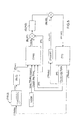
Figure 4 shows a control diagram similar to that inFigure 3 , but with additional operating blocks; -
Figure 5 shows a control diagram similar to that inFigure 4 , but with an additional block representing control logic that takes into account certain operating parameters; -
Figure 6 shows a block diagram of the control method of the system. -
Number 10 inFigure 1 indicates as a whole a drive between anengine 11 and arear axle 12 of a vehicle (only shown partly). -
Drive 10 comprises in known manner a number of mechanical devices arranged in series. - More specifically, a clutch 13 (advantageously, though not necessarily, an oil-bath clutch) is located downstream from
engine 1, and is followed by a variable-speed drive 14 which transmits power from aninput shaft 15 to an output shaft 16 (parallel to input shaft 15) fitted with a measuring device 17 for measuring the output torque from variable-speed drive 14. - More specifically, variable-
speed drive 14 comprises twopulleys pulleys 14A*, 14A** and 14B*, 14B**. - Half-
pulleys 14A*, 14A** are coaxial withinput shaft 15, and half-pulleys 14B*, 14B** are coaxial withoutput shaft 16. - Half-
pulleys 14A*, 14A** and 14B*, 14B** are movable in respective two-way directions (F1) and (F2). - To do so, each
pulley hydraulic actuator pulleys 14A*, 14A**, 14B*, 14B** against each other to adjust the velocity ratio ofshafts - More specifically, half-
pulley 14A* is fitted to ashaft 21 fitted with agear 22 that meshes with asun gear 23 of anepicyclic gear train 24. - Similarly, half-
pulley 14B* is fitted to ashaft 25 fitted with agear 26 that meshes with aplanet carrier 27 forming part ofepicyclic gear train 24. - The two motions of
gears epicyclic gear train 24 to rotate apinion 28 that meshes with abevel gear 29 that transmits motion to a differential 30 and therefore to rearaxle 12 fitted with the rear wheels (not shown) of the vehicle. - Clutch 13 is operated in known manner by an
actuator 31 that determines the (percentage) "degree of engagement" of clutch 13 (see below); and the way in whichclutch 13 is engaged in turn determines the travelling direction (forward/reverse) of the vehicle. -
Actuators speed drive 14,actuator 31 ofclutch 31, and measuring device 17 for measuring the output torque of variable-speed drive 14 are connected functionally to an electronic central control unit (CC) which, as will be seen, forms part of acontrol system 100 implementing a control method for controlling the torque transferable bydrive 10. As described in detail below, electronic central control unit (CC) therefore imparts commands to the control devices ofactuators drive 10 according to user requirements and the intrinsic capacity ofdrive 10. - An alternative embodiment has only one actuator, which controls the variable-speed drive and moves the two
pulleys - In the
Figure 2 graph, the y axis shows the input speed of variable-speed drive 14 measured oninput shaft 15, and the x axis the maximum torques frompulley 14A of variable-speed drive 14. - The
Figure 2 graph also shows a number of curves (C1), (C2), (C3), (C4), (C5), (C6) parameterized with respect to the velocity ratio τ=(N2/N1), where N1 is the number of revolutions ofpulley 14A, and N2 the number of revolutions ofpulley 14B. - Velocity ratio (τ) may of course be adjusted by appropriately operating
actuators - Curves (C1), (C2), (C3), (C4), (C5), (C6) are interpreted, for example, as follows :
- assuming a speed of 2000 rpm of
shaft 15 and a velocity ratio (τ)=0.41 (curve (C1)), this means the useful diameter ofpulley 14A is small with respect to that ofpulley 14B, which means that, in the example considered, no more than 90 Nm (obviously minus a safety factor) can "pass" throughpulley 14A; otherwise,pulley 14A may be even irreparably damaged; - assuming the same speed of 2000 rpm of
shaft 15, but a velocity ratio (τ) of variable-speed drive 14 of 0.69, for example, (curve (C2)), the torque that can "pass" throughpulley 14A increases to roughly 115 Nm, which is as to be expected, since increasing velocity ratio (τ) also increases the useful diameter ofpulley 14A. - More specifically, the system may be said to directly measure a pressure (Pf) as opposed to torque.
- Pressure (Pf) is then converted to a torque on the basis of a physical law provided by the supplier; at which point, the resulting torque may be "transferred" upstream or downstream of variable-
speed drive 14 using velocity ratio (τ). -
Figure 3 shows the basic principles of the control method according to the present invention. - A start value (τ1) of the velocity ratio between the pulleys of variable-
speed drive 14, and a start value (v1) of the speed ofinput shaft 15 are recorded on a tractor (TT) . - Using a graph of the type shown in
Figure 2 , and entering values (τ1) and (v1), a maximum permissible torque value (Tmax) for variable-speed drive 14 in those work conditions is obtained. - In a block (BLC), the maximum permissible torque value (Tmax) is converted to a maximum permissible pressure value (Pfmax) .
- Electronic central control unit (CC) then compares the pressure value (Pf) recorded on tractor (TT) with the maximum permissible pressure value (Pfmax). If (Pf) is greater than (Pfmax), the work pressure (Pclutch) of
clutch 13 is set to a theoretical value (Pclutch*) which theoretically produces a pressure (Pf) of variable-speed drive 14 lower than or at most equal to (Pfmax). - Accordingly,
clutch 13 is partly released (and set to pressure value (Pclutch*)) and begins "slipping", thus transmitting less torque to variable-speed drive 14. - In
Figure 4 , a subtraction block (BLST) is added to theFigure 3 control diagram, and is followed by a PID (proportional-integral-derivative) controller (CLPID). - The feedback signal reprocessed by controller (CLPID) is sent to an adding block (BLSS), where it is added to theoretical value (Pclutch*) and sent to
clutch 13 of tractor (TT). - This feedback serves to compensate for any errors in calculating theoretical value (Pclutch*).
- If the control logic were to maintain a (Pclutch) value giving a variable-speed-
drive 14 pressure of (Pfmax), the user would be unaware of the condition, andclutch 13 would be damaged. So, to solve the problem, the control logic, as opposed to limiting variable-speed-drive 14 pressure (Pfmax), controls (Pf) usingclutch 13 as an actuator. - All this is shown in
Figure 5 , which has an additional block (TPM) (Torque Pressure Management) which represents a control logic that controls the setpoint of (Pf) taking into account the user request, the measured slip ratio, and the measured (Pf) value. - In the example shown, (Pfsetpoint) is controlled to give the user the impression the system is limiting. This is done by gradually reducing (Pfsetpoint) (thus reducing the slip ratio) if user request exceeds the capacity of the system. After a given time, if the load is still too high,
clutch 13 is released, and the user is requested to reset the operation (i.e. to release the accelerator pedal). -
Figure 6 shows a flow chart of the logic operations performed by the control system to achieve the above. - The system is initialized by making (Pfsetpoint) equal to (Pfmax), which means that, when initialized, the system always has maximum pull capacity.
- The first thing checked in the control loop is the measured value of (Pf), i.e. the torque to variable-
speed drive 14. If (Pf) is over 75% of permissible torque (Pfmax), the system proceeds to check slip ofclutch 13. - If the previous condition is met, the current engagement ratio of
clutch 13 is checked. - If the current engagement ratio of
clutch 13 is over 70%, (Pfsetpoint) is made equal to the maximum value (or increased if it was previously reduced) to regain full "pull" capacity of the system. - The velocity ratio (τ) of variable-
speed drive 14 is that requested by the user. - If the current engagement ratio of
clutch 13 ranges between 30% and 70%, (Pfsetpoint) is reduced by a low reduction factor to make less pull capacity available to the user. The requested velocity ratio (τ) of variable-speed drive 14 is that requested by the user. - If the engagement ratio ranges between 2.5% and 30%, (Pfsetpoint) is reduced by an intermediate reduction factor to make even less pull capacity available to the user. The requested velocity ratio (τ) is the minimum ratio, thus bypassing user request.
- If the engagement ratio is less than 2.5%, (Pfsetpoint) is reduced by a high reduction factor to make even less torque available to the user. The requested velocity ratio (τ) of variable-
speed drive 14 is the minimum ratio, thus bypassing user request. - If (Pfsetpoint) becomes less than (Pfmin), the clutch is released by the control logic to prevent it from overheating, and a control panel issues an "Rp" ("Release Pedal") user message, i.e. the system tells the user to release the control pedal and possibly start another sequence.
- Conversely, if the measured (Pf) value is less than 75% of (Pfmax), then (Pfsetpoint), if not already the maximum permissible, is increased by a given factor until it reaches the maximum value (this occurs, for example, when, after a period in which the slip control is active, the load ceases, thus returning the resisting torque, and therefore (Pf), to below 75% of the permissible value.
- If the slip control is active (measured (Pf) value over 75% of the permissible value), it is only deactivated if (Pf) is found to have fallen below 75% of the permissible value for more than 800 ms.
- As shown in the
Figure 6 flow chart, if the clutch engagement ratio is less than 30%, the control logic bypasses the user velocity ratio request and assigns a minimum velocity ratio target. - This assignment derives from a design constraint in the system. That is, variable-
speed drive 14 can only be moved if there is movement at the twopulleys - Obviously, if
clutch 13 is released (thus cutting off motion to variable-speed drive 14) when variable-speed drive 14 is not at minimum velocity ratio (τ), it follows that, at the next startup, clutch 13 will be reengaged with variable-speed drive 14 at a high velocity ratio (τ), thus possibly resulting in stalling of engine 11 (Figure 1 ). - To prevent this, as the torque control releases clutch 13 (engagement ratio of less than 30%), the system sets variable-
speed drive 14 to the minimum velocity ratio (τ) , to ensure the most favourable start condition of variable-speed drive 14 at the next startup. - The main advantage of the system and method described lies in perfectly controlling the torque transferable by a mechanical drive, and in fully safeguarding the component parts of the mechanical drive itself.
Claims (15)
- A system (100) for controlling the torque transferable by a mechanical drive (10) between an engine (11) and a shaft (12) of a vehicle; said mechanical drive (10) comprising:- a clutch (13); and- a variable-speed drive (14) for transmitting motion between an input shaft (15) and an output shaft (16);
said system (100) being characterized by comprising:- first actuating means (19, 20) which act on at least one member (14A, 14B) of said variable-speed drive (14);- second actuating means (31) which act on at least a clutch (13); said second actuating means (31) determining the degree of engagement/release of said clutch (13); and- measuring means (17) for measuring the torque to or from said variable-speed drive (14);
said first and second actuating means (19, 20, 31) and said measuring means (17) being controlled by an electronic central control unit ((CC)) to protect said variable-speed drive (14) and/or said clutch (13) from mechanical overloading of the mechanical drive (10). - A method of controlling the torque transferable by a mechanical drive, the method being characterized by:- recording torque transmission on a variable-speed drive; and- setting the degree of release/engagement of a clutch as a function of said torque transmission recorded on the variable-speed drive.
- A method as claimed in Claim 2, characterized in that:- an initial value (τ1) of the velocity ratio between the pulleys of the variable-speed drive, and an initial value (v1) of the speed of the input shaft of the variable-speed drive are recorded;- from values (τ1) and (v1), a maximum permissible torque value (Tmax) is obtained for the variable-speed drive in those work conditions;- in a block (BLC), the maximum permissible torque value (Tmax) is converted to a maximum permissible pressure value (Pfmax);- electronic means ((CC)) compare a recorded pressure value (Pf) and the maximum permissible pressure value (Pfmax);- if the value of (Pf) is greater than (Pfmax), the work pressure (Pclutch) of the clutch is set to a theoretical value (Pclutch*) which theoretically produces a pressure (Pf) on the variable-speed drive lower than or at most equal to the value of (Pfmax); the clutch is therefore partly released (and set to a pressure value (Pclutch*)) and begins "slipping", thus transmitting less torque to the variable-speed drive.
- A method as claimed in Claim 3, characterized by comprising:- an operation performed by a subtraction block (BLST) and followed by an operation performed by a PID (proportional-integral-derivative) controller (CLPID);- the feedback signal reprocessed by the controller (CLPID) is sent to an adding block (BLSS), where it is added to the theoretical value (Pclutch*) and sent to the clutch;- the control logic, as opposed to limiting variable-speed-drive pressure (Pfmax), controls (Pf) using the clutch as an actuator.
- A method as claimed in Claim 4, characterized by comprising:- a further operation performed in a block (TPM) (Torque Pressure Management) which represents a control logic that controls (Pfsetpoint) taking into account the user request, the measured slip ratio, and the measured (Pf) value.
- A method as claimed in Claim 5, characterized in that:- (Pfsetpoint) is controlled to give the user the impression the system is limiting; this is done by gradually reducing (Pfsetpoint) if user request exceeds the capacity of the system; and, after a given time, if the load is still too high, the clutch is released, and the user is requested to reset the operation
- A method as claimed in Claim 2, characterized in that:- the system is initialized by making (Pfsetpoint) equal to (Pfmax);- if (Pf) is over 75% of permissible torque (Pfmax), the system proceeds to check slip of the clutch;- if the previous condition is met, the current engagement ratio of the clutch is checked;- if the current engagement ratio of the clutch is over 70%, (Pfsetpoint) is made equal to the maximum value (or increased if it was previously reduced) to regain full "pull" capacity of the system; in which case, the velocity ratio (τ) of the variable-speed drive is that requested by the user.
- A method as claimed in Claim 2, characterized in that:- if the current engagement ratio of the clutch ranges between 30% and 70%, (Pfsetpoint) is reduced by a low reduction factor to make less pull capacity available to the user; and the requested velocity ratio (τ) of the variable-speed drive is that requested by the user.
- A method as claimed in Claim 2, characterized in that:- if the engagement ratio ranges between 2.5% and 30%, (Pfsetpoint) is reduced by an intermediate reduction factor to make even less pull capacity available to the user; and the requested velocity ratio (τ) is the minimum ratio, thus bypassing user request.
- A method as claimed in Claim 2, characterized in that:- if the engagement ratio is less than 2.5%, (Pfsetpoint) is reduced by a high reduction factor to make even less torque available to the user; and the requested velocity ratio (τ) of the variable-speed drive is the minimum ratio, thus bypassing user request.
- A method as claimed in any one of Claims 9-12,
characterized in that :- if (Pfsetpoint) becomes less than (Pfmin), the clutch is released by the control logic to prevent it from overheating, and a control panel issues an "Rp" ("Release Pedal") user message, i.e. the system tells the user to release the control pedal and possibly start another sequence. - A method as claimed in Claim 2, characterized in that:- if the measured (Pf) value is less than 75% of (Pfmax), then (Pfsetpoint), if not already the maximum permissible, is increased by a given factor to the maximum value.
- A method as claimed in Claim 2, characterized in that:- if the slip control is active (measured (Pf) value over 75% of the permissible value), it is only deactivated if (Pf) is found to have fallen below 75% of the permissible value for more than a given time lapse.
- A method as claimed in Claim 15, characterized in that:- if the clutch engagement ratio is less than 30%, the control logic bypasses the user velocity ratio request and assigns a minimum velocity ratio target.
- A method as claimed in Claim 2, characterized in that:- as the torque control releases the clutch (with an engagement ratio below a given value), the variable-speed drive is set to the minimum velocity ratio (τ), to ensure favourable start conditions of the variable-speed drive at the next startup.
Priority Applications (2)
| Application Number | Priority Date | Filing Date | Title |
|---|---|---|---|
| AT10153739T ATE557217T1 (en) | 2009-02-20 | 2010-02-16 | METHOD FOR CONTROLLING THE TORQUE TRANSMITTED BY A MECHANICAL DRIVE WITH A WET CLUTCH |
| EP10153739A EP2221513B1 (en) | 2009-02-20 | 2010-02-16 | Method for controlling the torque transferable by a mechanical drive employing an oil-bath clutch. |
Applications Claiming Priority (2)
| Application Number | Priority Date | Filing Date | Title |
|---|---|---|---|
| IT000097A ITBO20090097A1 (en) | 2009-02-20 | 2009-02-20 | EQUIPMENT AND RELATED METHOD OF CONTROL OF THE TORQUE TRANSMISSIBLE IN A MECHANICAL TRANSMISSION USING A CLUTCH IN OIL BATH |
| EP10153739A EP2221513B1 (en) | 2009-02-20 | 2010-02-16 | Method for controlling the torque transferable by a mechanical drive employing an oil-bath clutch. |
Publications (2)
| Publication Number | Publication Date |
|---|---|
| EP2221513A1 true EP2221513A1 (en) | 2010-08-25 |
| EP2221513B1 EP2221513B1 (en) | 2012-05-09 |
Family
ID=41076703
Family Applications (1)
| Application Number | Title | Priority Date | Filing Date |
|---|---|---|---|
| EP10153739A Active EP2221513B1 (en) | 2009-02-20 | 2010-02-16 | Method for controlling the torque transferable by a mechanical drive employing an oil-bath clutch. |
Country Status (4)
| Country | Link |
|---|---|
| US (1) | US8403810B2 (en) |
| EP (1) | EP2221513B1 (en) |
| AT (1) | ATE557217T1 (en) |
| IT (1) | ITBO20090097A1 (en) |
Families Citing this family (1)
| Publication number | Priority date | Publication date | Assignee | Title |
|---|---|---|---|---|
| CN106422442A (en) * | 2016-11-24 | 2017-02-22 | 无锡市通用机械厂有限公司 | Center driving device with overload protection function |
Citations (2)
| Publication number | Priority date | Publication date | Assignee | Title |
|---|---|---|---|---|
| US6179739B1 (en) | 1998-12-30 | 2001-01-30 | Hamilton Sunstrand Corporation | Continuously variable transmission with control arrangement and method for preventing transmission belt slippage |
| US20070184936A1 (en) | 2006-02-06 | 2007-08-09 | Fuji Jukogyo Kabushiki Kaisha | Control apparatus for vehicle |
Family Cites Families (5)
| Publication number | Priority date | Publication date | Assignee | Title |
|---|---|---|---|---|
| CH669287A5 (en) * | 1986-03-25 | 1989-02-28 | Carl Geisser | TOOL FOR MOUNTING CABLE END SLEEVES, CABLE END SLEEVE MAGAZINE AND DEVICE FOR THE PRODUCTION THEREOF. |
| US6171212B1 (en) * | 1997-08-26 | 2001-01-09 | Luk Getriebe Systeme Gmbh | Method of and apparatus for controlling the operation of a clutch in the power train of a motor vehicle |
| JP3498901B2 (en) * | 1998-12-25 | 2004-02-23 | 日産自動車株式会社 | Control device for belt-type continuously variable transmission |
| ITBO20080597A1 (en) * | 2008-09-30 | 2010-04-01 | Cnh Italia Spa | CONTROL OF A CONTINUOUS VARIABLE TRANSMISSION |
| JP5171799B2 (en) * | 2008-12-18 | 2013-03-27 | 日産自動車株式会社 | Control device for belt type continuously variable transmission |
-
2009
- 2009-02-20 IT IT000097A patent/ITBO20090097A1/en unknown
-
2010
- 2010-02-16 AT AT10153739T patent/ATE557217T1/en active
- 2010-02-16 EP EP10153739A patent/EP2221513B1/en active Active
- 2010-02-19 US US12/709,342 patent/US8403810B2/en not_active Expired - Fee Related
Patent Citations (2)
| Publication number | Priority date | Publication date | Assignee | Title |
|---|---|---|---|---|
| US6179739B1 (en) | 1998-12-30 | 2001-01-30 | Hamilton Sunstrand Corporation | Continuously variable transmission with control arrangement and method for preventing transmission belt slippage |
| US20070184936A1 (en) | 2006-02-06 | 2007-08-09 | Fuji Jukogyo Kabushiki Kaisha | Control apparatus for vehicle |
Also Published As
| Publication number | Publication date |
|---|---|
| US8403810B2 (en) | 2013-03-26 |
| EP2221513B1 (en) | 2012-05-09 |
| ATE557217T1 (en) | 2012-05-15 |
| ITBO20090097A1 (en) | 2010-08-21 |
| US20100216595A1 (en) | 2010-08-26 |
Similar Documents
| Publication | Publication Date | Title |
|---|---|---|
| CN111795083B (en) | Transmission Clutch Brake Control System | |
| CN107499305B (en) | System and method for controlling backlash in a vehicle powertrain | |
| EP2072365B1 (en) | Work machine including an internal combustion machine and an infinitely variable transmission coupled with the internal combustion engine | |
| EP2068043B1 (en) | Working machine and method | |
| US20120101678A1 (en) | Control apparatus for vehicle | |
| WO2014020685A1 (en) | Vehicle transmission controller | |
| US9944285B2 (en) | Hybrid vehicle and lash mitigation strategy | |
| CN102410365A (en) | Gear shifting and protection control strategy of wet clutch for continuously variable transmission | |
| WO2007074374A2 (en) | Method for controlling engine braking in a vehicle powertrain | |
| CN112744210A (en) | Power control system with transmission instantaneous power boost function | |
| CN108025639B (en) | Drivetrain implementing automatic direction change braking | |
| CN103238010A (en) | How to adjust the working pressure of the transmission | |
| US10174694B2 (en) | Method of optimizing vehicle performance based on countershaft acceleration | |
| EP2169276A1 (en) | Control of a continuously variable transmission | |
| US9752304B2 (en) | Work vehicle and method of controlling work vehicle | |
| US10011282B2 (en) | Prime mover arrangement and method for controlling speed and torque output of a prime mover arrangement | |
| EP2221513B1 (en) | Method for controlling the torque transferable by a mechanical drive employing an oil-bath clutch. | |
| CN108025749B (en) | Transmission system implementing automatic direction change braking | |
| US6945907B2 (en) | Method and apparatus for controlling the operation of a motor vehicle drive train | |
| JP2020536199A (en) | Vehicle launch control method | |
| JPWO2011010548A1 (en) | Vehicle control device | |
| WO2026074946A1 (en) | Work vehicle |
Legal Events
| Date | Code | Title | Description |
|---|---|---|---|
| PUAI | Public reference made under article 153(3) epc to a published international application that has entered the european phase |
Free format text: ORIGINAL CODE: 0009012 |
|
| AK | Designated contracting states |
Kind code of ref document: A1 Designated state(s): AT BE BG CH CY CZ DE DK EE ES FI FR GB GR HR HU IE IS IT LI LT LU LV MC MK MT NL NO PL PT RO SE SI SK SM TR |
|
| AX | Request for extension of the european patent |
Extension state: AL BA RS |
|
| RAP1 | Party data changed (applicant data changed or rights of an application transferred) |
Owner name: CNH ITALIA S.P.A. |
|
| RAP1 | Party data changed (applicant data changed or rights of an application transferred) |
Owner name: CNH ITALIA S.P.A. |
|
| 17P | Request for examination filed |
Effective date: 20110225 |
|
| GRAP | Despatch of communication of intention to grant a patent |
Free format text: ORIGINAL CODE: EPIDOSNIGR1 |
|
| RTI1 | Title (correction) |
Free format text: METHOD FOR CONTROLLING THE TORQUE TRANSFERABLE BY A MECHANICAL DRIVE EMPLOYING AN OIL-BATH CLUTCH. |
|
| GRAS | Grant fee paid |
Free format text: ORIGINAL CODE: EPIDOSNIGR3 |
|
| GRAA | (expected) grant |
Free format text: ORIGINAL CODE: 0009210 |
|
| AK | Designated contracting states |
Kind code of ref document: B1 Designated state(s): AT BE BG CH CY CZ DE DK EE ES FI FR GB GR HR HU IE IS IT LI LT LU LV MC MK MT NL NO PL PT RO SE SI SK SM TR |
|
| REG | Reference to a national code |
Ref country code: GB Ref legal event code: FG4D |
|
| REG | Reference to a national code |
Ref country code: AT Ref legal event code: REF Ref document number: 557217 Country of ref document: AT Kind code of ref document: T Effective date: 20120515 Ref country code: CH Ref legal event code: EP |
|
| REG | Reference to a national code |
Ref country code: IE Ref legal event code: FG4D |
|
| REG | Reference to a national code |
Ref country code: DE Ref legal event code: R096 Ref document number: 602010001322 Country of ref document: DE Effective date: 20120705 |
|
| REG | Reference to a national code |
Ref country code: NL Ref legal event code: VDEP Effective date: 20120509 |
|
| REG | Reference to a national code |
Ref country code: LT Ref legal event code: MG4D Effective date: 20120509 |
|
| PG25 | Lapsed in a contracting state [announced via postgrant information from national office to epo] |
Ref country code: SE Free format text: LAPSE BECAUSE OF FAILURE TO SUBMIT A TRANSLATION OF THE DESCRIPTION OR TO PAY THE FEE WITHIN THE PRESCRIBED TIME-LIMIT Effective date: 20120509 Ref country code: LT Free format text: LAPSE BECAUSE OF FAILURE TO SUBMIT A TRANSLATION OF THE DESCRIPTION OR TO PAY THE FEE WITHIN THE PRESCRIBED TIME-LIMIT Effective date: 20120509 Ref country code: PL Free format text: LAPSE BECAUSE OF FAILURE TO SUBMIT A TRANSLATION OF THE DESCRIPTION OR TO PAY THE FEE WITHIN THE PRESCRIBED TIME-LIMIT Effective date: 20120509 Ref country code: NO Free format text: LAPSE BECAUSE OF FAILURE TO SUBMIT A TRANSLATION OF THE DESCRIPTION OR TO PAY THE FEE WITHIN THE PRESCRIBED TIME-LIMIT Effective date: 20120809 Ref country code: CY Free format text: LAPSE BECAUSE OF FAILURE TO SUBMIT A TRANSLATION OF THE DESCRIPTION OR TO PAY THE FEE WITHIN THE PRESCRIBED TIME-LIMIT Effective date: 20120509 Ref country code: FI Free format text: LAPSE BECAUSE OF FAILURE TO SUBMIT A TRANSLATION OF THE DESCRIPTION OR TO PAY THE FEE WITHIN THE PRESCRIBED TIME-LIMIT Effective date: 20120509 Ref country code: IS Free format text: LAPSE BECAUSE OF FAILURE TO SUBMIT A TRANSLATION OF THE DESCRIPTION OR TO PAY THE FEE WITHIN THE PRESCRIBED TIME-LIMIT Effective date: 20120909 |
|
| REG | Reference to a national code |
Ref country code: AT Ref legal event code: MK05 Ref document number: 557217 Country of ref document: AT Kind code of ref document: T Effective date: 20120509 |
|
| PG25 | Lapsed in a contracting state [announced via postgrant information from national office to epo] |
Ref country code: GR Free format text: LAPSE BECAUSE OF FAILURE TO SUBMIT A TRANSLATION OF THE DESCRIPTION OR TO PAY THE FEE WITHIN THE PRESCRIBED TIME-LIMIT Effective date: 20120810 Ref country code: LV Free format text: LAPSE BECAUSE OF FAILURE TO SUBMIT A TRANSLATION OF THE DESCRIPTION OR TO PAY THE FEE WITHIN THE PRESCRIBED TIME-LIMIT Effective date: 20120509 Ref country code: PT Free format text: LAPSE BECAUSE OF FAILURE TO SUBMIT A TRANSLATION OF THE DESCRIPTION OR TO PAY THE FEE WITHIN THE PRESCRIBED TIME-LIMIT Effective date: 20120910 Ref country code: SI Free format text: LAPSE BECAUSE OF FAILURE TO SUBMIT A TRANSLATION OF THE DESCRIPTION OR TO PAY THE FEE WITHIN THE PRESCRIBED TIME-LIMIT Effective date: 20120509 Ref country code: HR Free format text: LAPSE BECAUSE OF FAILURE TO SUBMIT A TRANSLATION OF THE DESCRIPTION OR TO PAY THE FEE WITHIN THE PRESCRIBED TIME-LIMIT Effective date: 20120509 |
|
| PG25 | Lapsed in a contracting state [announced via postgrant information from national office to epo] |
Ref country code: BE Free format text: LAPSE BECAUSE OF FAILURE TO SUBMIT A TRANSLATION OF THE DESCRIPTION OR TO PAY THE FEE WITHIN THE PRESCRIBED TIME-LIMIT Effective date: 20120509 |
|
| PG25 | Lapsed in a contracting state [announced via postgrant information from national office to epo] |
Ref country code: AT Free format text: LAPSE BECAUSE OF FAILURE TO SUBMIT A TRANSLATION OF THE DESCRIPTION OR TO PAY THE FEE WITHIN THE PRESCRIBED TIME-LIMIT Effective date: 20120509 Ref country code: EE Free format text: LAPSE BECAUSE OF FAILURE TO SUBMIT A TRANSLATION OF THE DESCRIPTION OR TO PAY THE FEE WITHIN THE PRESCRIBED TIME-LIMIT Effective date: 20120509 Ref country code: SK Free format text: LAPSE BECAUSE OF FAILURE TO SUBMIT A TRANSLATION OF THE DESCRIPTION OR TO PAY THE FEE WITHIN THE PRESCRIBED TIME-LIMIT Effective date: 20120509 Ref country code: CZ Free format text: LAPSE BECAUSE OF FAILURE TO SUBMIT A TRANSLATION OF THE DESCRIPTION OR TO PAY THE FEE WITHIN THE PRESCRIBED TIME-LIMIT Effective date: 20120509 Ref country code: NL Free format text: LAPSE BECAUSE OF FAILURE TO SUBMIT A TRANSLATION OF THE DESCRIPTION OR TO PAY THE FEE WITHIN THE PRESCRIBED TIME-LIMIT Effective date: 20120509 Ref country code: DK Free format text: LAPSE BECAUSE OF FAILURE TO SUBMIT A TRANSLATION OF THE DESCRIPTION OR TO PAY THE FEE WITHIN THE PRESCRIBED TIME-LIMIT Effective date: 20120509 Ref country code: RO Free format text: LAPSE BECAUSE OF FAILURE TO SUBMIT A TRANSLATION OF THE DESCRIPTION OR TO PAY THE FEE WITHIN THE PRESCRIBED TIME-LIMIT Effective date: 20120509 |
|
| PLBE | No opposition filed within time limit |
Free format text: ORIGINAL CODE: 0009261 |
|
| STAA | Information on the status of an ep patent application or granted ep patent |
Free format text: STATUS: NO OPPOSITION FILED WITHIN TIME LIMIT |
|
| 26N | No opposition filed |
Effective date: 20130212 |
|
| PG25 | Lapsed in a contracting state [announced via postgrant information from national office to epo] |
Ref country code: ES Free format text: LAPSE BECAUSE OF FAILURE TO SUBMIT A TRANSLATION OF THE DESCRIPTION OR TO PAY THE FEE WITHIN THE PRESCRIBED TIME-LIMIT Effective date: 20120820 |
|
| REG | Reference to a national code |
Ref country code: DE Ref legal event code: R097 Ref document number: 602010001322 Country of ref document: DE Effective date: 20130212 |
|
| PG25 | Lapsed in a contracting state [announced via postgrant information from national office to epo] |
Ref country code: BG Free format text: LAPSE BECAUSE OF FAILURE TO SUBMIT A TRANSLATION OF THE DESCRIPTION OR TO PAY THE FEE WITHIN THE PRESCRIBED TIME-LIMIT Effective date: 20120809 |
|
| PG25 | Lapsed in a contracting state [announced via postgrant information from national office to epo] |
Ref country code: MC Free format text: LAPSE BECAUSE OF NON-PAYMENT OF DUE FEES Effective date: 20130228 |
|
| REG | Reference to a national code |
Ref country code: IE Ref legal event code: MM4A |
|
| PG25 | Lapsed in a contracting state [announced via postgrant information from national office to epo] |
Ref country code: IE Free format text: LAPSE BECAUSE OF NON-PAYMENT OF DUE FEES Effective date: 20130216 |
|
| REG | Reference to a national code |
Ref country code: DE Ref legal event code: R082 Ref document number: 602010001322 Country of ref document: DE Representative=s name: PATENTANWAELTE WALLACH, KOCH & PARTNER, DE |
|
| PG25 | Lapsed in a contracting state [announced via postgrant information from national office to epo] |
Ref country code: MT Free format text: LAPSE BECAUSE OF FAILURE TO SUBMIT A TRANSLATION OF THE DESCRIPTION OR TO PAY THE FEE WITHIN THE PRESCRIBED TIME-LIMIT Effective date: 20120509 |
|
| REG | Reference to a national code |
Ref country code: DE Ref legal event code: R081 Ref document number: 602010001322 Country of ref document: DE Owner name: CNH INDUSTRIAL ITALIA S.P.A., IT Free format text: FORMER OWNER: CNH ITALIA S.P.A., TURIN, IT Effective date: 20140623 Ref country code: DE Ref legal event code: R082 Ref document number: 602010001322 Country of ref document: DE Representative=s name: PATENTANWAELTE WALLACH, KOCH & PARTNER, DE Effective date: 20140623 Ref country code: DE Ref legal event code: R082 Ref document number: 602010001322 Country of ref document: DE Representative=s name: PATENTANWAELTE WALLACH, KOCH, DR. HAIBACH, FEL, DE Effective date: 20140623 |
|
| REG | Reference to a national code |
Ref country code: CH Ref legal event code: PL |
|
| PG25 | Lapsed in a contracting state [announced via postgrant information from national office to epo] |
Ref country code: LI Free format text: LAPSE BECAUSE OF NON-PAYMENT OF DUE FEES Effective date: 20140228 Ref country code: CH Free format text: LAPSE BECAUSE OF NON-PAYMENT OF DUE FEES Effective date: 20140228 |
|
| REG | Reference to a national code |
Ref country code: FR Ref legal event code: CD Owner name: CNH INDUSTRIAL ITALIA S.P.A. Effective date: 20150313 |
|
| PG25 | Lapsed in a contracting state [announced via postgrant information from national office to epo] |
Ref country code: SM Free format text: LAPSE BECAUSE OF FAILURE TO SUBMIT A TRANSLATION OF THE DESCRIPTION OR TO PAY THE FEE WITHIN THE PRESCRIBED TIME-LIMIT Effective date: 20120509 |
|
| PG25 | Lapsed in a contracting state [announced via postgrant information from national office to epo] |
Ref country code: TR Free format text: LAPSE BECAUSE OF FAILURE TO SUBMIT A TRANSLATION OF THE DESCRIPTION OR TO PAY THE FEE WITHIN THE PRESCRIBED TIME-LIMIT Effective date: 20120509 |
|
| PG25 | Lapsed in a contracting state [announced via postgrant information from national office to epo] |
Ref country code: LU Free format text: LAPSE BECAUSE OF NON-PAYMENT OF DUE FEES Effective date: 20130216 Ref country code: HU Free format text: LAPSE BECAUSE OF FAILURE TO SUBMIT A TRANSLATION OF THE DESCRIPTION OR TO PAY THE FEE WITHIN THE PRESCRIBED TIME-LIMIT; INVALID AB INITIO Effective date: 20100216 Ref country code: MK Free format text: LAPSE BECAUSE OF FAILURE TO SUBMIT A TRANSLATION OF THE DESCRIPTION OR TO PAY THE FEE WITHIN THE PRESCRIBED TIME-LIMIT Effective date: 20120509 |
|
| REG | Reference to a national code |
Ref country code: FR Ref legal event code: PLFP Year of fee payment: 7 |
|
| REG | Reference to a national code |
Ref country code: FR Ref legal event code: PLFP Year of fee payment: 8 |
|
| REG | Reference to a national code |
Ref country code: FR Ref legal event code: PLFP Year of fee payment: 9 |
|
| PGFP | Annual fee paid to national office [announced via postgrant information from national office to epo] |
Ref country code: GB Payment date: 20200219 Year of fee payment: 11 |
|
| REG | Reference to a national code |
Ref country code: DE Ref legal event code: R082 Ref document number: 602010001322 Country of ref document: DE Representative=s name: MEISSNER BOLTE PATENTANWAELTE RECHTSANWAELTE P, DE |
|
| REG | Reference to a national code |
Ref country code: DE Ref legal event code: R084 Ref document number: 602010001322 Country of ref document: DE |
|
| GBPC | Gb: european patent ceased through non-payment of renewal fee |
Effective date: 20210216 |
|
| PG25 | Lapsed in a contracting state [announced via postgrant information from national office to epo] |
Ref country code: GB Free format text: LAPSE BECAUSE OF NON-PAYMENT OF DUE FEES Effective date: 20210216 |
|
| PGFP | Annual fee paid to national office [announced via postgrant information from national office to epo] |
Ref country code: FR Payment date: 20240227 Year of fee payment: 15 |
|
| PG25 | Lapsed in a contracting state [announced via postgrant information from national office to epo] |
Ref country code: FR Free format text: LAPSE BECAUSE OF NON-PAYMENT OF DUE FEES Effective date: 20250228 |
|
| PGFP | Annual fee paid to national office [announced via postgrant information from national office to epo] |
Ref country code: DE Payment date: 20260220 Year of fee payment: 17 |
|
| PGFP | Annual fee paid to national office [announced via postgrant information from national office to epo] |
Ref country code: IT Payment date: 20260220 Year of fee payment: 17 |