EP2221246A2 - Variable geometry aerofoil - Google Patents
Variable geometry aerofoil Download PDFInfo
- Publication number
- EP2221246A2 EP2221246A2 EP10152953A EP10152953A EP2221246A2 EP 2221246 A2 EP2221246 A2 EP 2221246A2 EP 10152953 A EP10152953 A EP 10152953A EP 10152953 A EP10152953 A EP 10152953A EP 2221246 A2 EP2221246 A2 EP 2221246A2
- Authority
- EP
- European Patent Office
- Prior art keywords
- geometry
- aerofoil
- composite material
- surface part
- support structure
- Prior art date
- Legal status (The legal status is an assumption and is not a legal conclusion. Google has not performed a legal analysis and makes no representation as to the accuracy of the status listed.)
- Granted
Links
Images


Classifications
-
- B—PERFORMING OPERATIONS; TRANSPORTING
- B64—AIRCRAFT; AVIATION; COSMONAUTICS
- B64C—AEROPLANES; HELICOPTERS
- B64C3/00—Wings
- B64C3/38—Adjustment of complete wings or parts thereof
- B64C3/44—Varying camber
- B64C3/48—Varying camber by relatively-movable parts of wing structures
-
- B—PERFORMING OPERATIONS; TRANSPORTING
- B64—AIRCRAFT; AVIATION; COSMONAUTICS
- B64C—AEROPLANES; HELICOPTERS
- B64C9/00—Adjustable control surfaces or members, e.g. rudders
-
- B—PERFORMING OPERATIONS; TRANSPORTING
- B64—AIRCRAFT; AVIATION; COSMONAUTICS
- B64C—AEROPLANES; HELICOPTERS
- B64C11/00—Propellers, e.g. of ducted type; Features common to propellers and rotors for rotorcraft
- B64C11/16—Blades
- B64C11/20—Constructional features
-
- B—PERFORMING OPERATIONS; TRANSPORTING
- B64—AIRCRAFT; AVIATION; COSMONAUTICS
- B64C—AEROPLANES; HELICOPTERS
- B64C27/00—Rotorcraft; Rotors peculiar thereto
- B64C27/54—Mechanisms for controlling blade adjustment or movement relative to rotor head, e.g. lag-lead movement
- B64C27/58—Transmitting means, e.g. interrelated with initiating means or means acting on blades
- B64C27/59—Transmitting means, e.g. interrelated with initiating means or means acting on blades mechanical
- B64C27/615—Transmitting means, e.g. interrelated with initiating means or means acting on blades mechanical including flaps mounted on blades
-
- B—PERFORMING OPERATIONS; TRANSPORTING
- B64—AIRCRAFT; AVIATION; COSMONAUTICS
- B64C—AEROPLANES; HELICOPTERS
- B64C27/00—Rotorcraft; Rotors peculiar thereto
- B64C27/54—Mechanisms for controlling blade adjustment or movement relative to rotor head, e.g. lag-lead movement
- B64C27/72—Means acting on blades
-
- F—MECHANICAL ENGINEERING; LIGHTING; HEATING; WEAPONS; BLASTING
- F01—MACHINES OR ENGINES IN GENERAL; ENGINE PLANTS IN GENERAL; STEAM ENGINES
- F01D—NON-POSITIVE DISPLACEMENT MACHINES OR ENGINES, e.g. STEAM TURBINES
- F01D5/00—Blades; Blade-carrying members; Heating, heat-insulating, cooling or antivibration means on the blades or the members
- F01D5/12—Blades
- F01D5/14—Form or construction
- F01D5/148—Blades with variable camber, e.g. by ejection of fluid
-
- F—MECHANICAL ENGINEERING; LIGHTING; HEATING; WEAPONS; BLASTING
- F05—INDEXING SCHEMES RELATING TO ENGINES OR PUMPS IN VARIOUS SUBCLASSES OF CLASSES F01-F04
- F05D—INDEXING SCHEME FOR ASPECTS RELATING TO NON-POSITIVE-DISPLACEMENT MACHINES OR ENGINES, GAS-TURBINES OR JET-PROPULSION PLANTS
- F05D2300/00—Materials; Properties thereof
- F05D2300/50—Intrinsic material properties or characteristics
- F05D2300/501—Elasticity
-
- F—MECHANICAL ENGINEERING; LIGHTING; HEATING; WEAPONS; BLASTING
- F05—INDEXING SCHEMES RELATING TO ENGINES OR PUMPS IN VARIOUS SUBCLASSES OF CLASSES F01-F04
- F05D—INDEXING SCHEME FOR ASPECTS RELATING TO NON-POSITIVE-DISPLACEMENT MACHINES OR ENGINES, GAS-TURBINES OR JET-PROPULSION PLANTS
- F05D2300/00—Materials; Properties thereof
- F05D2300/60—Properties or characteristics given to material by treatment or manufacturing
- F05D2300/603—Composites; e.g. fibre-reinforced
-
- Y—GENERAL TAGGING OF NEW TECHNOLOGICAL DEVELOPMENTS; GENERAL TAGGING OF CROSS-SECTIONAL TECHNOLOGIES SPANNING OVER SEVERAL SECTIONS OF THE IPC; TECHNICAL SUBJECTS COVERED BY FORMER USPC CROSS-REFERENCE ART COLLECTIONS [XRACs] AND DIGESTS
- Y02—TECHNOLOGIES OR APPLICATIONS FOR MITIGATION OR ADAPTATION AGAINST CLIMATE CHANGE
- Y02T—CLIMATE CHANGE MITIGATION TECHNOLOGIES RELATED TO TRANSPORTATION
- Y02T50/00—Aeronautics or air transport
- Y02T50/10—Drag reduction
-
- Y—GENERAL TAGGING OF NEW TECHNOLOGICAL DEVELOPMENTS; GENERAL TAGGING OF CROSS-SECTIONAL TECHNOLOGIES SPANNING OVER SEVERAL SECTIONS OF THE IPC; TECHNICAL SUBJECTS COVERED BY FORMER USPC CROSS-REFERENCE ART COLLECTIONS [XRACs] AND DIGESTS
- Y02—TECHNOLOGIES OR APPLICATIONS FOR MITIGATION OR ADAPTATION AGAINST CLIMATE CHANGE
- Y02T—CLIMATE CHANGE MITIGATION TECHNOLOGIES RELATED TO TRANSPORTATION
- Y02T50/00—Aeronautics or air transport
- Y02T50/30—Wing lift efficiency
-
- Y—GENERAL TAGGING OF NEW TECHNOLOGICAL DEVELOPMENTS; GENERAL TAGGING OF CROSS-SECTIONAL TECHNOLOGIES SPANNING OVER SEVERAL SECTIONS OF THE IPC; TECHNICAL SUBJECTS COVERED BY FORMER USPC CROSS-REFERENCE ART COLLECTIONS [XRACs] AND DIGESTS
- Y02—TECHNOLOGIES OR APPLICATIONS FOR MITIGATION OR ADAPTATION AGAINST CLIMATE CHANGE
- Y02T—CLIMATE CHANGE MITIGATION TECHNOLOGIES RELATED TO TRANSPORTATION
- Y02T50/00—Aeronautics or air transport
- Y02T50/60—Efficient propulsion technologies, e.g. for aircraft
Definitions
- This invention relates to a structure which in use is subject to fluid flow. More particularly but not exclusively the invention relates to an aerofoil device especially of an aircraft, such as a rotor blade of a rotary wing aircraft such as a helicopter, or a wing of a non-rotary wing aircraft.
- the invention has application to other aerofoil devices, such as for examples only, propellers and turbine blades, and yet more generally to any device which in use is subject to fluid flow and there is a requirement to vary the geometry of at least a part of the device in use, to affect fluid flow.
- Aerofoil devices which have ailerons, trim tabs and flaps at the trailing edge of a main body of the aerofoil, which provide airflow control surfaces to vary the effective camber of the aerofoil.
- control surfaces are separate from a main aerofoil body and are moveable relative the main aerofoil body by one or more actuators, which when the control surface is moved to a desired position relative to the main aerofoil structure, serve to maintain the control surface in that position.
- FIG 2a A main aerofoil device, indicated at 15, has at the trailing edge 22 thereof, a control surface i.e.
- bi-stable composite material for an outer surface part of the device.
- the geometry of such material may be changed between one stable geometry and another by some actuator.
- such proposals have presented practical difficulties in achieving reliable changes between bi-stable geometries, whilst ensuring that the bi-stable outer surface part material is able to provide enough structural stiffness to withstand geometrical distortions due to dynamic fluid loads experienced in use as the fluid flows over the outer surface part.
- the support structure is preferably internal of the device, and includes a plurality of support members of the composite material.
- the fibres of the composite material may be glass or carbon fibres, or other suitable fibres which may even not yet be developed, whilst the matrix material is preferably a material which is unaffected by hygrothermal changes which may be experienced in use, such as for example an epoxy resin.
- the support structure for the outer surface part may include an anchor to which one end of the or each member of the composite material, is held.
- the anchor for the or each composite material member may be provided by a respective recess in a spar of the device, and one end of the composite material member or members may be secured in the or the respective recesses by any desired fixing means, such as for example a bonding agent.
- both of the upper and lower surface skins extend continuously beyond the main body each to provide respectively, an upper outer surface part and a lower outer surface part of the device, and the support structure is located at least in part between the upper outer surface part provided by the upper surface skin and the lower outer surface part provided by the lower surface skin.
- the or each outer surface part which is supported by the support structure is at a trailing edge of the aerofoil device.
- the aerofoil device may be one of an aircraft wing and a rotor blade which extends substantially straight among its span, and the outer surface part or together the upper and lower outer surface parts, may provide a control surface being an aileron, trim tab, or flap.
- the upper camber surface 24 of the aerofoil device 15 its provided by an upper surface skin 24a which, in this example, extends continuously from at or adjacent the leading edge 21 of the aerofoil device 15, to the trailing edge 22 and beyond to provide an upper outer surface part 24b of the control surface 30.
- the lower camber surface 25 of the aerofoil device 15 is provided by a lower surface skin 25a which also extends, in this example, continuously from at or adjacent the leading edge 21 of the aerofoil device 15, to the trailing edge 22 and beyond to provide a lower outer surface part 25b of the control surface 30.
- the one ends of the support members 32 may be retained in their respective recesses 33a of the spar 33 by any desired fixing device, or as in the example, the one ends may be bonded in the recesses 33a with a suitable bonding agent for example.
- End parts of the upper and lower outer surface parts 24b, 25b provided by the upper and lower surface skins 24, 25 of the aerofoil device 15, and the opposite ends 32b of the composite material members 32 are received by a channel of the trailing edge member 34.
- the trailing edge member 34 may be secured to the end parts of each of the upper and lower outer surface parts 24b, 25b e.g. by a bonding agent.
- the opposite ends 32b of each of the composite material members 32 may be held to each other where received by the trailing edge member 34, or may simply be retained by being trapped between the upper and lower outer surface parts 24b, 25b.
- the actuating device 50 may include a motive unit 52 such as for examples only, an electric motor, a hydraulic or pneumatic fluid motor or actuator, or a piezoelectric device, and a pair of pulling elements, in the example, connecting flexible cables 54, 55.
- the flexible cables 54, 55 are each connected at one end to the motive device 52 such that either cable 54, 55 can selectively be pulled by appropriate operation of the motive unit 52.
- the pulling elements could be rigid or semi-rigid elements, or may be part rigid and part flexible along their lengths. Where rigid, the necessary force to change the members 32 from one stable state to another, may be applied by pushing instead of pulling.
- One of the cables 54 extends via a first actuation path, towards the trailing edge 22 of the aerofoil device 15, and then the upper cable 54 is guided closely beneath the upper outer surface part 24b of the control surface 30.
- the other cable 55 a lower cable, similarly extends via a second actuation path, towards the trailing edge 22 of the aerofoil device 15, and then the lower cable 55 is guided closely above the lower outer surface part 25b of the control surface 30.
- the configuration of the infernal support structure 31 as shown in figures 3a , 3b and figure 5 is purely illustrative and exemplary. Any number of support members 32 necessary to effect a variation in the geometry of the upper and lower outer surface parts 24b, 25b of the control surface 30 may be provided, and these may be of different length and configuration to the members 32 shown and described. Also, any appropriate number of members 32 may be selected to achieve the necessary stiffness of the upper and lower outer surface parts 24b, 25b to resist geometrical distortion when experiencing dynamic fluid loads, which could otherwise effect an undesirable change of geometry of the support members 32 other than under or controller pilot control.
- control surface 30 extends along part of the span of the blade 15. Where the span extent of the control surface 30 is long, the actuating apparatus 50 may have more than one upper and lower cable 54, 55 or other pulling members along the span, to apply the necessary forces to the supporting structure to effect the variation in geometry of the upper and lower outer surface parts 24b, 25b of the control surface 30 along its entice length.
- control surface 30 is a tab e.g. as suggested in figure 6
- a plurality of independently actuable such tabs along the span length, each having a variable geometry in accordance with the invention, may be utilised.
Landscapes
- Engineering & Computer Science (AREA)
- Aviation & Aerospace Engineering (AREA)
- Mechanical Engineering (AREA)
- General Engineering & Computer Science (AREA)
- Structures Of Non-Positive Displacement Pumps (AREA)
- Toys (AREA)
- Wind Motors (AREA)
- Moulding By Coating Moulds (AREA)
Abstract
Description
- This invention relates to a structure which in use is subject to fluid flow. More particularly but not exclusively the invention relates to an aerofoil device especially of an aircraft, such as a rotor blade of a rotary wing aircraft such as a helicopter, or a wing of a non-rotary wing aircraft.
- However the invention has application to other aerofoil devices, such as for examples only, propellers and turbine blades, and yet more generally to any device which in use is subject to fluid flow and there is a requirement to vary the geometry of at least a part of the device in use, to affect fluid flow.
- Rotor blades for example, have a main body with an outer surface including an upper camber surface and a lower camber surface, and a leading edge and a trailing edge, a blade tip and a root end. The trailing edge particularly of the blade may have attached to it, a control surface, such as for example only, a flap, the position of which is variable to affect fluid flow over the device, for example to improve the performance of the blade, during the transition between hover and forward flight. For example the flap may be lowered from its usual raised position when the helicopter is in forward flight, to a lowered position to improve performance in hover.
- Aerofoil devices are known which have ailerons, trim tabs and flaps at the trailing edge of a main body of the aerofoil, which provide airflow control surfaces to vary the effective camber of the aerofoil. Typically such control surfaces are separate from a main aerofoil body and are moveable relative the main aerofoil body by one or more actuators, which when the control surface is moved to a desired position relative to the main aerofoil structure, serve to maintain the control surface in that position. An example of such a prior art aerofoil is illustrated in
figure 2a . A main aerofoil device, indicated at 15, has at thetrailing edge 22 thereof, a control surface i.e. aflap 30 which is pivoted to themain body 15a of theaerofoil structure 15, and is moveable up and down to change the effective camber of the aerofoil for different flight conditions. Thecontrol surface 30 is pivoted by an actuator which also serves to maintain the position of thecontrol surface 30, and hence the effective camber, in a selected position. - It has been proposed to utilise for an aerofoil device control surface, bi-stable composite material for an outer surface part of the device. The geometry of such material may be changed between one stable geometry and another by some actuator. However hithertofore, such proposals have presented practical difficulties in achieving reliable changes between bi-stable geometries, whilst ensuring that the bi-stable outer surface part material is able to provide enough structural stiffness to withstand geometrical distortions due to dynamic fluid loads experienced in use as the fluid flows over the outer surface part.
- According to a first aspect of the invention we provide a device which in use is subject to fluid flow, the device including an outer surface part the geometry of which is variable to affect the fluid flow, the device including a support structure which supports the outer surface part, the support structure including a member of composite material the geometry of which is changeable by an actuating apparatus between a first stable geometry and a second stable geometry to effect variation in the geometry of the outer surface part.
- The present invention, by using the composite material with the bi-stable geometry for a support member of the internal support structure rather than outer surface part of the device, provides greater design flexibility both to ensure reliable changes in geometry between the first and second stable geometry of the composite material member and hence more reliable effecting of variation in the geometry of the outer surface part, whilst providing sufficient stiffness to the outer surface part to withstand geometrical distortions due to dynamic fluid loads experienced in use as the fluid flows over the outer surface part.
- However the invention enjoys the advantage that the composite material member of the device maintains the first or second stable geometry without any influence from the actuating apparatus and when the geometry is changed to the second or first stable geometry respectively.
- As the actuating apparatus used in the present invention is not required to maintain the geometry of the device, power is not required to maintain the geometry, and lighter apparatus may be provided which may require less components than conventional actuating apparatus.
- This contrasts with conventional aerofoils, for example as shown in
figure 2a , in which an actuator serves not only to vary the aerofoil geometry by moving a control surface, but to maintain the aerofoil geometry by holding the control surface in a selected position. - Although any actuating apparatus which is capable of changing the geometry of the composite material member may be used, such as a mechanical actuator, a piezoelectric actuated actuator, or an electrical actuator for examples only, in each case preferably the actuating apparatus effects changes between the first and second stable geometries by applying a mechanical force to a part of the composite material member.
- In order to ensure that the support structure provides sufficient structural stiffness to the outer surface part to withstand geometrical distortions due to dynamic fluid loads experienced in use as the fluid flows over the outer surface part, the support structure is preferably internal of the device, and includes a plurality of support members of the composite material.
- In one example the composite material of the or each support member is a laminated composite material including a plurality of laminate layers of fibres embedded in set matrix material, at least one of the laminate layers including a region of fibres which were stressed prior to the matrix material setting. The fibres of the laminate layers of the or each of the members of composite material, are preferably substantially aligned within that layer, and any fibres which are pre-stressed fibres in the or each member preferably extend in a common direction to establish a unidirectional stress field in the internal support structure.
- By establishing a unidirectional stress field, the composite material member or members will, upon changing from one stable geometry to the other stable geometry, buckle rather than warp, so as to achieve maximum variation in the geometry of the outer surface part supported by the support structure.
- Thus where there are a plurality of composite material members, the geometries of each of the members may be changed by an actuating apparatus force acting in a single direction, and the plurality of members together may provide the desired stiffness to the outer surface part.
- The fibres of the composite material may be glass or carbon fibres, or other suitable fibres which may even not yet be developed, whilst the matrix material is preferably a material which is unaffected by hygrothermal changes which may be experienced in use, such as for example an epoxy resin. The support structure for the outer surface part may include an anchor to which one end of the or each member of the composite material, is held. The anchor for the or each composite material member may be provided by a respective recess in a spar of the device, and one end of the composite material member or members may be secured in the or the respective recesses by any desired fixing means, such as for example a bonding agent.
- Where the internal support structure includes a plurality of composite material members, the opposite ends of each member to the one ends held by the anchor, may be held together in a manner to permit of differential movement of the members at the opposite ends. As the opposite ends are not rigidly fixed relative to one another (like the one ends), the composite material members will not provide resistance to a change in geometry of others of the composite material members.
- Where the or each composite material member includes fibres which are all substantially aligned with a unidirectional pre-sfiress field, the or each member may extend from the anchor in the direction of the stress field.
- The invention has particularly but not exclusively been developed for an aerofoil device which includes a main body which has an upper camber surface and a lower camber surface, and a leading edge and a trailing edge. The upper and lower camber surfaces may be provided at least in part by respective upper and lower surface skins, at least one of the upper and lower surface skins extending continuously beyond the main body to provide at least a part of the outer surface part of the device.
- When the outer surface part is supported by the internal support structure with one geometry, the respective extending upper and/or lower surface of the aerofoil device thus may have a first effective camber and when the outer surface part is supported with another geometry, the respective upper and/or lower surface of the aerofoil device may have a second alternative effective camber.
- Unlike a conventional aerofoil device in which a control surface e.g. such as a flap, is pivoted to the main aerofoil body and is thus a separate component attached to the main body, using the present invention the upper and/or lower surface skin of the main body is an integral part of the control surface.
- The skin will need to be sufficiently flexible to permit of the variations in the geometry of the outer surface part.
- Desirably both of the upper and lower surface skins extend continuously beyond the main body each to provide respectively, an upper outer surface part and a lower outer surface part of the device, and the support structure is located at least in part between the upper outer surface part provided by the upper surface skin and the lower outer surface part provided by the lower surface skin.
- In one proposal, the or each outer surface part which is supported by the support structure is at a trailing edge of the aerofoil device. The aerofoil device may be one of an aircraft wing and a rotor blade which extends substantially straight among its span, and the outer surface part or together the upper and lower outer surface parts, may provide a control surface being an aileron, trim tab, or flap.
- The outer surface part or together the upper and lower outer surface parts, may thus extend along a span of the aerofoil.
- In another example, the aerofoil device may be one of a turbine blade and a propeller which includes a twist along its span.
- According to a second aspect of the invention we provide a method of operating an aircraft which includes a device of the first aspect of the invention which is an aerofoil device being one of an aircraft wing and a rotor blade which extends substantially straight along its span, the aerofoil inducing a main body which has an upper camber surface and a lower camber surface, and a leading edge and a trailing edge and in which the upper and lower camber surfaces are provided at least in part by respective upper and lower surface skins, at least one of the upper and lower surface skins extending continuously beyond the main body to provide at least a part of the outer surface part,of the device, the method including, in flight, effecting a variation in the geometry of the upper and lower outer surface parts of the aerofoil device, to affect airflow over the aerofoil device, by operating the actuating apparatus thereby to change the geometry of the member or members of composite material of the internal support structure which supports the upper and lower outer surface parts, from a first stable geometry to a second stable geometry.
- Where the aerofoil device is a rotor blade of a rotary wing aircraft, the variation in the geometry of the upper and lower outer surface parts may be effected for different flight conditions; e.g. one geometry may be adapted for hover and another for forward flight; e.g. during the transition between hover and forward fight.
- According to a third aspect of the invention we provide an aircraft having a device according to the first aspect of the invention, the device being one of a wing and a rotor blade which extends substantially straight along its span.
- Embodiments of the invention will now be described with reference to the accompanying drawings in which:-
-
FIGURE 1 is an illustrative perspective view of a rotary wing aircraft having a rotary wing device in accordance with the present invention; -
FIGURES 2a and 2b are illustrative cross sections through respectively, a rotary wing device of a prior art rotary wing device and a rotary wing device in accordance with the present invention; -
FIGURES 3a and3b are illustrations showing the alternative positions of a control surface at a trailing edge of the structure offigure 2b achieved by an internal support structure with bi-stable members; -
FIGURE 4a illustrates a step in a method of pre-stressing a composite material; -
FIGURE 4b is a side illustration of a bi-stable member in two alternative stable states; -
FIGURE 5 is a more detailed sectional view, similar tofigure 2b ; -
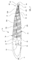
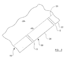
FIGURE 6 is an illustrative plan view of part of the rotary wing offigure 5 . - Referring to
figure 1 , a rotary wing aircraft i.e. ahelicopter 10 includes abody 12 housing a power source e.g. an engine E, for rotating a main sustainingrotor system 14 about a generally upright axis A, to generate lift and as desired to move theaircraft 10 though the air, or to permit theaircraft 10 to hover. Thehelicopter 10 of the example also includes a tail rotor system T. - The main sustaining
rotor system 14 in this example, includes five rotary wings orblades 15, one of which is illustrated in cross section infigure 2b . Eachrotor blade 15 is an aerofoil device which is substantival straight along its span from aroot end 19 where theblade 15 is connected to arotary hub 18 which is rotated through a transmission by the aircraft engine E, to ablade trip 20. - Each
blade 15 is an aerofoil device, including a leadingedge 21 and atrailing edge 22, and theblade 15 generates lift as air flows chord wise over anupper camber surface 24 and alower camber surface 25 between the leading andtrailing edges - Conventionally, such
aerofoil devices 15 include control surfaces which are moveable relative to amain rotor body 15a, to vary the geometry of the aerofoil device15 and thus affect airflow over theaerofoil device 15. Infigure 2a , such a conventional arrangement is illustrated in which at thetrailing edge 22 of therotor blade 15, a control surface separate to a mainrotor blade body 15a, is provided, indicated at 30. Thecontrol surface 30 is moveable between raised and lowered positions by an actuator such as a motor, linear or rotary hydraulic actuator, or even a piezoelectric type of actuator, which is provided internally of the mainrotor blade body 15a. Thus the geometry or effective camber of theblade 15 is varied by moving thecontrol surface 30, although the actual geometries of themain rotor body 15a and of thecontrol surface 30 themselves do not vary, only the relative position of thecontrol surface 30 to themain rotor body 15a. -
Such control surfaces 30 are moveable to affect airflow over the aerofoil device15 to suit different flight conditions thus to optimise e.g. lift or speed as desired. The present invention has particularly been devised to facilitate the varying of therotor 15 geometry in the transition when thehelicopter 10 is changing between hover (when thecontrol surface 30 may be lowered for maximum lift) and forward flight (when thecontrol surface 30 may rise to minimise drag). - An
aerofoil device 15 in accordance with the present invention is illustrated infigure 2b . in the figure it can be seen that thecontrol surface 30 has a first lowered position and a second raised position. However thecontrol surface 30 is not separate from amain rotor body 15a: Rather, the geometry of upper and lower outer surface parts of thecontrol surface 30 is varied between the lowered and raised positions shown. - In
figure 5 more detail of theaerofoil device 15 can be seen. Theupper camber surface 24 of theaerofoil device 15 its provided by anupper surface skin 24a which, in this example, extends continuously from at or adjacent the leadingedge 21 of theaerofoil device 15, to the trailingedge 22 and beyond to provide an upperouter surface part 24b of thecontrol surface 30. Thelower camber surface 25 of theaerofoil device 15 is provided by alower surface skin 25a which also extends, in this example, continuously from at or adjacent the leadingedge 21 of theaerofoil device 15, to the trailingedge 22 and beyond to provide a lowerouter surface part 25b of thecontrol surface 30. - Of course to permit the
control surface 30 to move between its raised and lowered positions, the upper and lowerouter surface parts edge 22, or the upper andlower skins figure 6 at S. - Between the upper and lower
outer surface parts internal support structure 31 which supports the upper and lowerouter surface parts control surface 30, and whichinternal support structure 31 effects the variation in geometry of the upper and lowerouter surface parts control surface 30. Referring also tofigures 3a and3b it can be seen that internally within thecontrol surface 30, theinternal support structure 31 includes a plurality ofsupport members 32. Thesesupport members 32 are each made of an intelligent responsive composite material, theinternal support structure 31 in this examples, including at least sixsuch support members 32 each of which extends from one end, where thesupport members 32 are each fixed to an anchor of thesupport structure 31, provided by arespective recess 33a in aspar 33 of themain rotor body 15a, to an opposite end indicated at 32b. Thespar 33 preferably extends for the full span length of theblade 15, but could be local only to thecontrol surface 30 as required. - The one ends of the
support members 32 may be retained in theirrespective recesses 33a of thespar 33 by any desired fixing device, or as in the example, the one ends may be bonded in therecesses 33a with a suitable bonding agent for example. - The
control surface 30 includes in this example, a trailingedge member 34 which receives the opposite ends 32b of each of thesupport members 32 to thespar 33, in a manner as described below. - The bi-stable composite material of the
support members 32 naturally and inherently adopt one of two bi-stable conditions, one of these being shown infigure 3a and the other infigure 3b . - Such composite materials themselves are generally known.
- In the present example the
members 32 are made from a plurality of laminated layers (seefigure 4a ) 35a, 35b, 35c, 35d, which are bonded together. Eachlayer - It can be seen that the fibres in each of the
layers layers 35b, 35c extend generally orthogonally to the fibres in the outer twolayers layers figure 4a , opposite edge regions R1 and R2, are pre-stressed i.e. the fibres in these regions R1 and R2 were stressed lengthwise prior to being embedded in the set matrix material. - By pre-stressing the fibres in the
outer layers composite material member 32 adopting a cambered configuration e.g. as indicated in full lines infigure 4b . However the configuration of thecomposite material member 32 can be changed to the cambered configuration indicated infigure 4b by dotted lines, by applying an actuating (mechanical) force to themember 32, to cause buckling of the member. The unidirectional stress field ensures that themember 32 buckles as described along its length, rather than for example, warps, for example with a twist. - Each of the six
support members 32 are arranged one on top of each other between the upper and lowerouter surfaces control surface 30, so that themembers 32 extend from thespar 33 or other anchor to which their one ends are anchored, with their respective unidirectional stress fields aligned, i.e. the direction of the pre-stressed fibres aligned, to their opposite ends 32b to the trailingedge member 34. - End parts of the upper and lower
outer surface parts aerofoil device 15, and the opposite ends 32b of thecomposite material members 32, are received by a channel of the trailingedge member 34. The trailingedge member 34 may be secured to the end parts of each of the upper and lowerouter surface parts composite material members 32 may be held to each other where received by the trailingedge member 34, or may simply be retained by being trapped between the upper and lowerouter surface parts composite material members 32 are held to each other, differential movement or slipping between the opposite ends 32b of themembers 32 in their extension directions, must be permitted, as themembers 32 change geometry between the bi-stable configurations, i.e. between thefigure 3a andfigure 3b stable geometries. - This may be achieved using an elastic bonding agent, or some other holding means which permits such differential movement.
- It will be appreciated that upon the
composite material members 32 changing their geometries, this will effect a variation in geometry in each of the upper and lowerouter surface parts aerofoil device 15. - The
control surface 30 needs to be moved i.e. thecomposite material members 32 need to be moved between their bi-stable geometries, by an actuating apparatus, but as the first and second geometries of thecomposite material members 32 are stable i.e. the material buckles between one geometry and the other and maintains that geometry until forced to buckle in the opposite direction, the actuating apparatus is not required to hold thecontrol surface 30 in either of its raised or lowered positions. - As the
control surface 30 is not separate from themain structure 19 but thecontrol surface 30 is required to move between its raised and lowered positions as thecomposite material members 32 buckle between their bi-stable states, the upper and lower surface skins 24, 25, at least in the region where thecontrol surface 30 is adjacent to themain body 15 of theaerofoil device 15, i.e. the region, referenced 45, needs to accommodate variations in geometry and thus the upper and lower surface skins 24, 25 in theregion 45 need to be constructed to permit of moving of thecontrol surface 30 between its upper and lower positions. - In another example, the material of one or other of the upper and lower
outer surface parts support members 32, but it is the provision of the support structure ofmembers 32, internally of thecontrol surface 30 which provides reliability for varying the geometry of the upper/lowerouter surface parts outer surface parts control surface 30 experiences dynamic fluid loads in use. - An example of a suitable actuating apparatus which may be provided to vary the geometry of the
control surface 30 will now be described with reference tofigure 5 . - The
main body 15a of the aerofoil device 15 (which in this example is a helicopter rotor blade 15) includes an internal honeycomb structure over most of its volume between theleading edge 21 and the trailingedge 22. In another aerofoil device, such as a fixed wing of the aircraft, the wing may accommodate fuel storage tanks and/or other equipment. - In the case of a
rotor devices 15 though, it is desirable that therotor device 15 is balanced at a position about 25% of the chord length. Accordingly the actuating apparatus to be described and illustrated at 50, or at least the components of theapparatus 50 which contain the most weight, are accommodated towards the leadingedge 21 of therotor device 15, in a suitable hollow 51 distant chord-wise from thecontrol surface 30, at a position so as not to compromise the balance of therotor 15. - The
actuating device 50 may include amotive unit 52 such as for examples only, an electric motor, a hydraulic or pneumatic fluid motor or actuator, or a piezoelectric device, and a pair of pulling elements, in the example, connectingflexible cables flexible cables motive device 52 such that eithercable motive unit 52. In another example, the pulling elements could be rigid or semi-rigid elements, or may be part rigid and part flexible along their lengths. Where rigid, the necessary force to change themembers 32 from one stable state to another, may be applied by pushing instead of pulling. - One of the
cables 54, an upper cable, extends via a first actuation path, towards the trailingedge 22 of theaerofoil device 15, and then theupper cable 54 is guided closely beneath the upperouter surface part 24b of thecontrol surface 30. Theother cable 55, a lower cable, similarly extends via a second actuation path, towards the trailingedge 22 of theaerofoil device 15, and then thelower cable 55 is guided closely above the lowerouter surface part 25b of thecontrol surface 30. - Each of the
cables edge member 34 as indicated at C. - It will be appreciated that when the
motive unit 52 is operated to pull theupper cable 54, a mechanical force will be imparted to each of thecomposite material members 32 and the stable geometry shown infigure 3a , with thecontrol surface 30 in a raised condition, will be attained. By operating themotive unit 52 to pull thelower cable 55, a mechanical force will be imparted to each of thecomposite material members 32 and the other stable geometry shown infigure 3b , with thecontrol surface 30 in a lowered position will be attained. Of course when pulling eithercable motive unit 52, theother cable support members 32. - The
actuating apparatus 50 may be operated by a controller which may be automatically responsive to helicopter 12 operating conditions, and/or to pilot/operator control, to operate theactuating apparatus 50 to effect a change incontrol surface 30 position between the raised and lowered positions by moving thesupport members 32 between their first and second stable geometries. - Many modifications may be made without departing from the scope of the invention. For example the configuration of the
infernal support structure 31 as shown infigures 3a ,3b andfigure 5 is purely illustrative and exemplary. Any number ofsupport members 32 necessary to effect a variation in the geometry of the upper and lowerouter surface parts control surface 30 may be provided, and these may be of different length and configuration to themembers 32 shown and described. Also, any appropriate number ofmembers 32 may be selected to achieve the necessary stiffness of the upper and lowerouter surface parts support members 32 other than under or controller pilot control. - As can be seen from
figure 6 , thecontrol surface 30 extends along part of the span of theblade 15. Where the span extent of thecontrol surface 30 is long, theactuating apparatus 50 may have more than one upper andlower cable outer surface parts control surface 30 along its entice length. - Where the span extent of the
control surface 30 is small, so that the control surface is a tab e.g. as suggested infigure 6 , a plurality of independently actuable such tabs along the span length, each having a variable geometry in accordance with the invention, may be utilised. - The invention has been described particularly in relation to varying the geometry of upper and lower
outer surface parts control surface 30 at a trailingedge 22 of ahelicopter rotor blade 15, but as will be understood from the introduction to this specification, the invention has much wider application induing to control surfaces at aleading edge 21 of anaerofoil 15, and generally to a wing of an aerofoil of a non-rotary wing aircraft such as a fixed wing. The aircraft may be operated by a pilot or may be an un-manned aircraft. - The aorofoil need not be a
wing 15, but could be a rotor blade of the tail rotor system T of thehelicopter 15, or could be any other aerofoil or other device over which fluid flows in use, such as a propeller or turbine blade. - Instead of providing a trailing
edge member 34, or in addition, if desired the aerofoilouter surface skin support structure 31, or the opposite ends 32b of the compositematerial support members 32 may be un-enclosed at the trailingedge 22 of theaerofoil 15 by any skin ortrading edge member 34. - For further example the invention may be utilised to change the configuration of a surface part of an air intake or exhaust, or of an air flow cowling. The invention may be utilised for a device which is a fairing of a vehicle, e.g. a lorry tractor unit, to vary the geometry of an outer surface part of the fairing using a support structure having one or more composite material members the geometry of which can be changed between bi-stable states for optimum performance depending upon whether the tractor unit is towing a trailer or not.
- Thus whereas in the example described in which the invention is applied to a
control surface 30 having both an upperouter surface part 24b and a lowerouter surface part 25b, the invention may be applied to a device which has only a single outer surface part. - The invention is applicable not only to single main sustaining rotor helicopters such as shown in
figure 1 , but tandem sustaining rotor helicopters too. - The features disclosed in the foregoing description, or the following claims, or the accompanying drawings, expressed in their specific forms or in terms of a means for performing the disclosed function, or a method or process for attaining the disclosed result, as appropriate, may, separately, or in any combination of such features, be utilised for realising the invention in diverse forms thereof.
Claims (15)
- A device (15) which in use is subject to fluid flow, the device (15) including an outer surface part (24b, 25b) the geometry of which is variable to affect the fluid flow, the device (15) including a support structure (31) which supports the outer surface part, the support structure (31) being internal of the device (15) and including a plurality of support members (32) of composite material, the geometry of the support structure (31) being changeable by an actuating apparatus (50) between a first stable geometry and a second stable geometry to effect variation in the geometry of the outer surface part (24b, 25b), the support members (32) providing structural stiffness to the outer surface part (24b, 25b).
- A device according to claim 1 characterised in that the composite material of the structure (31) maintains the first or second stable geometry without any influence from the actuator apparatus (50) when the geometry is changed to the second or first stable geometry respectively.
- A device according to claim 1 or claim 2 characterised in that the actuating apparatus (50) effects changes between the first and second stable geometries by applying a mechanical force to a part of the composite material member.
- A device according to any one of the preceding claims characterised in that the composite material of each support member (32) is a laminated composite material including a plurality of laminate layers (35a - 35d) of fibres embedded in set matrix material, at least one of the laminate layers (35a - 35d) including a region (R1, R2) of fibres (35b, 35d) which were stressed prior to the matrix material setting, the fibres of the laminate layers of each of the support members (32) of composite material being substantially aligned within that layer, and any fibres (35b, 35d) which are pre-stressed fibres in the or each member (32) extend in a common direction and establish a unidirectional stress field in the internal support structure.
- A device according to claim 4 wherein the fibres are glass or carbon fibres and the matrix material is a material such as an epoxy resin, which is unaffected by hygrothermal changes.
- A device according to any one of the preceding claims characterised in that the support structure (31) of the outer surface part (24b, 25b) includes an anchor (33a) to which one end of each member (32) of the composite material, is held, the opposites ends of each support member being held together in a manner to permit of differential movement of the members (32) at the opposite ends.
- A device according to claim 6 where dependent upon claim 4, characterised in that each support member (32) extends from the anchor (33a) in the direction of the unidirectional stress field.
- A device according to any one of the preceding claims characterised in that the device (15) is an aerofoil device including a main body (15a) which has an upper camber surface (24) and a lower camber surface (25), and a leading edge (21) and a trailing edge (22), and the upper and lower camber surfaces (24, 25) are provided at least in part by respective upper and lower surface skins, at least one of the upper and lower surface skins (24, 25) extending continuously beyond the main body (1 5a) to provide at least a part of the outer surface part (24b, 25b) of the device (15).
- A device according to claim 8 characterised in that both of the upper and lower surface skins (24, 25) extend continuously beyond the main body (15a) each to provide respectively, an upper outer surface part (24b) and a lower outer surface part (25b) of the device (15), and the support structure (31) is located at least in part between the upper outer surface part (24b) provided by the upper surface skin and the lower outer surface part (25b) provided by the lower skin.
- A device according to claim 8 or claim 9 characterised in that the or each outer surface part (24b, 25b) which is supported by the support structure (31) is at a trailing edge (22) of the aerofoil device (15).
- A device according to any one of claims 8 to 10 which is one of an aircraft wing and a rotor blade (15) which extends substantially straight along its span, the outer surface part or together the upper and lower outer surface parts, providing a control surface being an aileron, trim tab, or flap which extends along part of a span of the aerofoil.
- A device according to any one of claims 1 to 10 which is one of a turbine blade and a propeller which includes a twist along its span.
- A method of operating an aircraft (10) which includes an aerofoil device (15) according to claim 11, the method including, in flight, effecting a variation in the geometry of the upper and lower outer surface parts (24b, 25b) of the aerofoil device (15), to affect air flow over the aerofoil device (15), by operating the actuating apparatus (50) thereby to change the geometry of support members (32) of composite material of the internal support structure (31) which supports the upper and lower outer surface parts (24b, 25b), from a first stable geometry to a second stable geometry.
- A method according to claim 13 characterised in that the aerofoil device is a rotor (15) blade of a rotary wing aircraft (10), and the variation in the geometry of the upper and lower outer surface parts (24b, 25b) is effected so that one geometry is adopted for hover and another for forward flight.
- An aircraft (10) having a device (15) according to any one of claims 1 to 12, the device (15) being one of a wing and a rotor blade which extends substantially straight along its span.
Priority Applications (1)
| Application Number | Priority Date | Filing Date | Title |
|---|---|---|---|
| EP16189998.4A EP3124376B1 (en) | 2009-02-20 | 2010-02-08 | Device which is subject to fluid flow |
Applications Claiming Priority (1)
| Application Number | Priority Date | Filing Date | Title |
|---|---|---|---|
| GB0902914.1A GB2467945B (en) | 2009-02-20 | 2009-02-20 | Device which is subject to fluid flow |
Related Child Applications (2)
| Application Number | Title | Priority Date | Filing Date |
|---|---|---|---|
| EP16189998.4A Division EP3124376B1 (en) | 2009-02-20 | 2010-02-08 | Device which is subject to fluid flow |
| EP16189998.4A Division-Into EP3124376B1 (en) | 2009-02-20 | 2010-02-08 | Device which is subject to fluid flow |
Publications (3)
| Publication Number | Publication Date |
|---|---|
| EP2221246A2 true EP2221246A2 (en) | 2010-08-25 |
| EP2221246A3 EP2221246A3 (en) | 2013-04-10 |
| EP2221246B1 EP2221246B1 (en) | 2016-11-02 |
Family
ID=40565472
Family Applications (2)
| Application Number | Title | Priority Date | Filing Date |
|---|---|---|---|
| EP16189998.4A Active EP3124376B1 (en) | 2009-02-20 | 2010-02-08 | Device which is subject to fluid flow |
| EP10152953.5A Active EP2221246B1 (en) | 2009-02-20 | 2010-02-08 | Variable geometry aerofoil |
Family Applications Before (1)
| Application Number | Title | Priority Date | Filing Date |
|---|---|---|---|
| EP16189998.4A Active EP3124376B1 (en) | 2009-02-20 | 2010-02-08 | Device which is subject to fluid flow |
Country Status (9)
| Country | Link |
|---|---|
| US (1) | US8191826B2 (en) |
| EP (2) | EP3124376B1 (en) |
| JP (1) | JP5598699B2 (en) |
| KR (1) | KR101729611B1 (en) |
| CN (1) | CN101811574B (en) |
| BR (2) | BR122019024196B8 (en) |
| CA (1) | CA2693641C (en) |
| GB (1) | GB2467945B (en) |
| RU (1) | RU2519602C2 (en) |
Cited By (3)
| Publication number | Priority date | Publication date | Assignee | Title |
|---|---|---|---|---|
| US20100181415A1 (en) * | 2007-06-28 | 2010-07-22 | Eurocopter Deutschland Gmbh | Rotor blade for a rotary wing aircraft |
| WO2012049500A1 (en) * | 2010-10-14 | 2012-04-19 | The University Of Bristol | A material, devices and structures including a material, and a method of forming a material |
| IT201800006527A1 (en) * | 2018-06-20 | 2019-12-20 | METHOD FOR THE REALIZATION OF PRESTRESSED SHELLS WITH CONTROLLED BISTABILITY; |
Families Citing this family (13)
| Publication number | Priority date | Publication date | Assignee | Title |
|---|---|---|---|---|
| US9944356B1 (en) * | 2009-03-25 | 2018-04-17 | Alexander T. Wigley | Shape shifting foils |
| EP2514669B1 (en) * | 2011-04-18 | 2014-09-10 | Claverham Limited | Active gurney flap |
| US8968437B2 (en) * | 2012-05-02 | 2015-03-03 | Michael J Kline | Jet engine with deflector |
| CN103085973A (en) * | 2012-12-26 | 2013-05-08 | 赵秋顺 | Carbon fiber rotary wing |
| CN103085967A (en) * | 2012-12-26 | 2013-05-08 | 赵秋顺 | Composite carbon fiber screw propeller |
| US9789956B2 (en) * | 2014-09-19 | 2017-10-17 | The Boeing Company | Vortex generators responsive to ambient conditions |
| GB2537630B (en) * | 2015-04-21 | 2020-11-04 | Agustawestland Ltd | An aerofoil |
| US20180319492A1 (en) * | 2015-11-09 | 2018-11-08 | Sikorsky Aircraft Corporation | Rotor blade structures |
| IT201600086511A1 (en) | 2016-08-22 | 2018-02-22 | Gen Electric | Air intake systems and related assembly methods |
| CN106516079B (en) * | 2016-10-28 | 2019-06-14 | 北京电子工程总体研究所(航天科工防御技术研究开发中心) | A kind of combined type aircraft based on MEMS |
| CN109515737B (en) * | 2018-03-16 | 2022-04-19 | 陕西飞机工业(集团)有限公司 | Aircraft wing surface leveling device |
| US11427306B2 (en) * | 2019-03-20 | 2022-08-30 | The Boeing Company | Piezoelectric thrust vector control for dual-mode unmanned aerial vehicle |
| RU2723567C1 (en) * | 2019-11-18 | 2020-06-16 | федеральное государственное бюджетное образовательное учреждение высшего образования "Пермский национальный исследовательский политехнический университет" | Propeller blade with controlled geometry of profile |
Family Cites Families (14)
| Publication number | Priority date | Publication date | Assignee | Title |
|---|---|---|---|---|
| US1856578A (en) * | 1929-05-15 | 1932-05-03 | Miquel Gabriel | Aeroplane |
| FR1334446A (en) * | 1961-06-28 | 1963-08-09 | Bolkow Entwicklungen Kg | Joint without friction |
| FR2765187B1 (en) * | 1997-06-25 | 1999-08-27 | Onera (Off Nat Aerospatiale) | BLADE PROFILE FOR AIRCRAFT ROTATING AIRCRAFT AND BLADE FOR ROTATING AIRCRAFT WITH SUCH A PROFILE |
| DE19808196C2 (en) * | 1998-02-27 | 2003-06-05 | Eurocopter Deutschland | Rotor blade for a helicopter |
| US6220550B1 (en) * | 1998-03-31 | 2001-04-24 | Continuum Dynamics, Inc. | Actuating device with multiple stable positions |
| RU2156207C2 (en) * | 1998-07-10 | 2000-09-20 | Казанский государственный технический университет им. А.Н. Туполева | Method of change of shaft of profile of flying vehicle lifting surfaces |
| DK1603798T3 (en) * | 2003-03-03 | 2011-02-14 | Flexsys Inc | Adaptable and flexible blade and rotor system |
| ATE429120T1 (en) * | 2003-04-17 | 2009-05-15 | Nokia Corp | BISTABLE SWIVEL LIMB AND MOBILE STATION THEREFOR &X9; |
| US6942455B2 (en) * | 2003-06-12 | 2005-09-13 | Sikorsky Aircraft Corporation | Strain isolated trim tab |
| DE102004056537B4 (en) * | 2004-11-23 | 2010-09-09 | Eads Deutschland Gmbh | Arrangement for reducing the aerodynamic noise on an additional wing of an aircraft |
| JP4568906B2 (en) * | 2004-12-16 | 2010-10-27 | 独立行政法人 宇宙航空研究開発機構 | Aircraft wing, aircraft wing composite, and manufacturing method thereof |
| US7321185B2 (en) * | 2005-03-04 | 2008-01-22 | United States Of America As Represented By The Administrator Of The National Aeronautics And Space Administration | Active multistable twisting device |
| GB0519502D0 (en) * | 2005-09-24 | 2005-11-02 | Rolls Royce Plc | Vane assembly |
| FR2898865B1 (en) * | 2006-03-27 | 2008-05-30 | Cetim Cermat Ass Loi De 1901 | AERODYNAMIC OR HYDRODYNAMIC PROFILE THAT CAN BE DEFORMED IN CONTINUOUS AND CONTROLLED MANNER |
-
2009
- 2009-02-20 GB GB0902914.1A patent/GB2467945B/en active Active
-
2010
- 2010-02-08 EP EP16189998.4A patent/EP3124376B1/en active Active
- 2010-02-08 EP EP10152953.5A patent/EP2221246B1/en active Active
- 2010-02-17 US US12/706,829 patent/US8191826B2/en active Active
- 2010-02-19 CA CA2693641A patent/CA2693641C/en active Active
- 2010-02-19 KR KR1020100015091A patent/KR101729611B1/en active Active
- 2010-02-19 RU RU2010105910/11A patent/RU2519602C2/en active
- 2010-02-20 CN CN201010114807.XA patent/CN101811574B/en active Active
- 2010-02-22 BR BR122019024196A patent/BR122019024196B8/en active IP Right Grant
- 2010-02-22 JP JP2010036194A patent/JP5598699B2/en active Active
- 2010-02-22 BR BRPI1000973A patent/BRPI1000973B8/en active IP Right Grant
Non-Patent Citations (1)
| Title |
|---|
| None |
Cited By (5)
| Publication number | Priority date | Publication date | Assignee | Title |
|---|---|---|---|---|
| US20100181415A1 (en) * | 2007-06-28 | 2010-07-22 | Eurocopter Deutschland Gmbh | Rotor blade for a rotary wing aircraft |
| WO2012049500A1 (en) * | 2010-10-14 | 2012-04-19 | The University Of Bristol | A material, devices and structures including a material, and a method of forming a material |
| IT201800006527A1 (en) * | 2018-06-20 | 2019-12-20 | METHOD FOR THE REALIZATION OF PRESTRESSED SHELLS WITH CONTROLLED BISTABILITY; | |
| WO2019244096A1 (en) * | 2018-06-20 | 2019-12-26 | Universita' Degli Studi Di Roma "La Sapienza" | Method for the realisation of prestressed shells with a controlled bistability |
| US11880636B2 (en) | 2018-06-20 | 2024-01-23 | Universita' Degli Studi Di Roma “La Sapienza” | Method for making prestressed shells having tunable bistability |
Also Published As
| Publication number | Publication date |
|---|---|
| CN101811574A (en) | 2010-08-25 |
| EP2221246A3 (en) | 2013-04-10 |
| EP3124376A1 (en) | 2017-02-01 |
| GB2467945A (en) | 2010-08-25 |
| JP2010208624A (en) | 2010-09-24 |
| US8191826B2 (en) | 2012-06-05 |
| BR122019024196B8 (en) | 2023-02-07 |
| CA2693641C (en) | 2016-07-12 |
| BRPI1000973A2 (en) | 2013-11-26 |
| KR20100095394A (en) | 2010-08-30 |
| BRPI1000973B8 (en) | 2022-12-13 |
| GB2467945B (en) | 2014-03-05 |
| JP5598699B2 (en) | 2014-10-01 |
| CN101811574B (en) | 2015-03-11 |
| RU2010105910A (en) | 2011-08-27 |
| BRPI1000973B1 (en) | 2020-08-04 |
| GB0902914D0 (en) | 2009-04-08 |
| EP2221246B1 (en) | 2016-11-02 |
| CA2693641A1 (en) | 2010-08-20 |
| US20100213320A1 (en) | 2010-08-26 |
| KR101729611B1 (en) | 2017-04-24 |
| EP3124376B1 (en) | 2019-04-24 |
| BR122019024196B1 (en) | 2021-01-19 |
| RU2519602C2 (en) | 2014-06-20 |
Similar Documents
| Publication | Publication Date | Title |
|---|---|---|
| EP2221246B1 (en) | Variable geometry aerofoil | |
| US10654557B2 (en) | Morphing skin for an aircraft | |
| US5887828A (en) | Seamless mission adaptive control surface | |
| EP3000722B1 (en) | Aircraft | |
| EP4116188B1 (en) | Aerofoil of an aerodynamic surface | |
| CA3016039C (en) | Edge morphing arrangement for an airfoil | |
| US20070114327A1 (en) | Wing load alleviation apparatus and method | |
| US8944365B2 (en) | Mission-adaptive rotor blade | |
| CN107719634A (en) | Variable Geometry Wing for aircraft | |
| WO2010119280A1 (en) | High lift devices for aircraft | |
| US8128020B2 (en) | Active twisting of an aircraft lifting surface via modulated clamping of substructure | |
| WO2016170341A1 (en) | Helicopter aerofoil with trailing edge flap | |
| US9604722B1 (en) | Mission-adaptive rotor blade |
Legal Events
| Date | Code | Title | Description |
|---|---|---|---|
| PUAI | Public reference made under article 153(3) epc to a published international application that has entered the european phase |
Free format text: ORIGINAL CODE: 0009012 |
|
| AK | Designated contracting states |
Kind code of ref document: A2 Designated state(s): AT BE BG CH CY CZ DE DK EE ES FI FR GB GR HR HU IE IS IT LI LT LU LV MC MK MT NL NO PL PT RO SE SI SK SM TR |
|
| PUAL | Search report despatched |
Free format text: ORIGINAL CODE: 0009013 |
|
| AK | Designated contracting states |
Kind code of ref document: A3 Designated state(s): AT BE BG CH CY CZ DE DK EE ES FI FR GB GR HR HU IE IS IT LI LT LU LV MC MK MT NL NO PL PT RO SE SI SK SM TR |
|
| RIC1 | Information provided on ipc code assigned before grant |
Ipc: B64C 11/20 20060101ALI20130301BHEP Ipc: B64C 3/48 20060101AFI20130301BHEP Ipc: B64C 27/615 20060101ALI20130301BHEP Ipc: B64C 27/72 20060101ALI20130301BHEP |
|
| 17P | Request for examination filed |
Effective date: 20131010 |
|
| RBV | Designated contracting states (corrected) |
Designated state(s): AT BE BG CH CY CZ DE DK EE ES FI FR GB GR HR HU IE IS IT LI LT LU LV MC MK MT NL NO PL PT RO SE SI SK SM TR |
|
| GRAP | Despatch of communication of intention to grant a patent |
Free format text: ORIGINAL CODE: EPIDOSNIGR1 |
|
| INTG | Intention to grant announced |
Effective date: 20160519 |
|
| GRAS | Grant fee paid |
Free format text: ORIGINAL CODE: EPIDOSNIGR3 |
|
| GRAA | (expected) grant |
Free format text: ORIGINAL CODE: 0009210 |
|
| AK | Designated contracting states |
Kind code of ref document: B1 Designated state(s): AT BE BG CH CY CZ DE DK EE ES FI FR GB GR HR HU IE IS IT LI LT LU LV MC MK MT NL NO PL PT RO SE SI SK SM TR |
|
| REG | Reference to a national code |
Ref country code: GB Ref legal event code: FG4D |
|
| REG | Reference to a national code |
Ref country code: AT Ref legal event code: REF Ref document number: 841544 Country of ref document: AT Kind code of ref document: T Effective date: 20161115 Ref country code: CH Ref legal event code: EP |
|
| REG | Reference to a national code |
Ref country code: IE Ref legal event code: FG4D |
|
| REG | Reference to a national code |
Ref country code: DE Ref legal event code: R096 Ref document number: 602010037576 Country of ref document: DE |
|
| REG | Reference to a national code |
Ref country code: FR Ref legal event code: PLFP Year of fee payment: 8 |
|
| PG25 | Lapsed in a contracting state [announced via postgrant information from national office to epo] |
Ref country code: LV Free format text: LAPSE BECAUSE OF FAILURE TO SUBMIT A TRANSLATION OF THE DESCRIPTION OR TO PAY THE FEE WITHIN THE PRESCRIBED TIME-LIMIT Effective date: 20161102 |
|
| RAP2 | Party data changed (patent owner data changed or rights of a patent transferred) |
Owner name: AGUSTAWESTLAND LIMITED |
|
| REG | Reference to a national code |
Ref country code: NL Ref legal event code: MP Effective date: 20161102 |
|
| REG | Reference to a national code |
Ref country code: LT Ref legal event code: MG4D |
|
| REG | Reference to a national code |
Ref country code: AT Ref legal event code: MK05 Ref document number: 841544 Country of ref document: AT Kind code of ref document: T Effective date: 20161102 |
|
| PG25 | Lapsed in a contracting state [announced via postgrant information from national office to epo] |
Ref country code: SE Free format text: LAPSE BECAUSE OF FAILURE TO SUBMIT A TRANSLATION OF THE DESCRIPTION OR TO PAY THE FEE WITHIN THE PRESCRIBED TIME-LIMIT Effective date: 20161102 Ref country code: NO Free format text: LAPSE BECAUSE OF FAILURE TO SUBMIT A TRANSLATION OF THE DESCRIPTION OR TO PAY THE FEE WITHIN THE PRESCRIBED TIME-LIMIT Effective date: 20170202 Ref country code: LT Free format text: LAPSE BECAUSE OF FAILURE TO SUBMIT A TRANSLATION OF THE DESCRIPTION OR TO PAY THE FEE WITHIN THE PRESCRIBED TIME-LIMIT Effective date: 20161102 Ref country code: NL Free format text: LAPSE BECAUSE OF FAILURE TO SUBMIT A TRANSLATION OF THE DESCRIPTION OR TO PAY THE FEE WITHIN THE PRESCRIBED TIME-LIMIT Effective date: 20161102 Ref country code: GR Free format text: LAPSE BECAUSE OF FAILURE TO SUBMIT A TRANSLATION OF THE DESCRIPTION OR TO PAY THE FEE WITHIN THE PRESCRIBED TIME-LIMIT Effective date: 20170203 |
|
| PG25 | Lapsed in a contracting state [announced via postgrant information from national office to epo] |
Ref country code: AT Free format text: LAPSE BECAUSE OF FAILURE TO SUBMIT A TRANSLATION OF THE DESCRIPTION OR TO PAY THE FEE WITHIN THE PRESCRIBED TIME-LIMIT Effective date: 20161102 Ref country code: IS Free format text: LAPSE BECAUSE OF FAILURE TO SUBMIT A TRANSLATION OF THE DESCRIPTION OR TO PAY THE FEE WITHIN THE PRESCRIBED TIME-LIMIT Effective date: 20170302 Ref country code: PT Free format text: LAPSE BECAUSE OF FAILURE TO SUBMIT A TRANSLATION OF THE DESCRIPTION OR TO PAY THE FEE WITHIN THE PRESCRIBED TIME-LIMIT Effective date: 20170302 Ref country code: HR Free format text: LAPSE BECAUSE OF FAILURE TO SUBMIT A TRANSLATION OF THE DESCRIPTION OR TO PAY THE FEE WITHIN THE PRESCRIBED TIME-LIMIT Effective date: 20161102 Ref country code: ES Free format text: LAPSE BECAUSE OF FAILURE TO SUBMIT A TRANSLATION OF THE DESCRIPTION OR TO PAY THE FEE WITHIN THE PRESCRIBED TIME-LIMIT Effective date: 20161102 Ref country code: FI Free format text: LAPSE BECAUSE OF FAILURE TO SUBMIT A TRANSLATION OF THE DESCRIPTION OR TO PAY THE FEE WITHIN THE PRESCRIBED TIME-LIMIT Effective date: 20161102 Ref country code: PL Free format text: LAPSE BECAUSE OF FAILURE TO SUBMIT A TRANSLATION OF THE DESCRIPTION OR TO PAY THE FEE WITHIN THE PRESCRIBED TIME-LIMIT Effective date: 20161102 Ref country code: BE Free format text: LAPSE BECAUSE OF NON-PAYMENT OF DUE FEES Effective date: 20170228 |
|
| PG25 | Lapsed in a contracting state [announced via postgrant information from national office to epo] |
Ref country code: SK Free format text: LAPSE BECAUSE OF FAILURE TO SUBMIT A TRANSLATION OF THE DESCRIPTION OR TO PAY THE FEE WITHIN THE PRESCRIBED TIME-LIMIT Effective date: 20161102 Ref country code: CZ Free format text: LAPSE BECAUSE OF FAILURE TO SUBMIT A TRANSLATION OF THE DESCRIPTION OR TO PAY THE FEE WITHIN THE PRESCRIBED TIME-LIMIT Effective date: 20161102 Ref country code: RO Free format text: LAPSE BECAUSE OF FAILURE TO SUBMIT A TRANSLATION OF THE DESCRIPTION OR TO PAY THE FEE WITHIN THE PRESCRIBED TIME-LIMIT Effective date: 20161102 Ref country code: DK Free format text: LAPSE BECAUSE OF FAILURE TO SUBMIT A TRANSLATION OF THE DESCRIPTION OR TO PAY THE FEE WITHIN THE PRESCRIBED TIME-LIMIT Effective date: 20161102 Ref country code: EE Free format text: LAPSE BECAUSE OF FAILURE TO SUBMIT A TRANSLATION OF THE DESCRIPTION OR TO PAY THE FEE WITHIN THE PRESCRIBED TIME-LIMIT Effective date: 20161102 |
|
| REG | Reference to a national code |
Ref country code: DE Ref legal event code: R097 Ref document number: 602010037576 Country of ref document: DE |
|
| PG25 | Lapsed in a contracting state [announced via postgrant information from national office to epo] |
Ref country code: SM Free format text: LAPSE BECAUSE OF FAILURE TO SUBMIT A TRANSLATION OF THE DESCRIPTION OR TO PAY THE FEE WITHIN THE PRESCRIBED TIME-LIMIT Effective date: 20161102 Ref country code: BG Free format text: LAPSE BECAUSE OF FAILURE TO SUBMIT A TRANSLATION OF THE DESCRIPTION OR TO PAY THE FEE WITHIN THE PRESCRIBED TIME-LIMIT Effective date: 20170202 Ref country code: BE Free format text: LAPSE BECAUSE OF FAILURE TO SUBMIT A TRANSLATION OF THE DESCRIPTION OR TO PAY THE FEE WITHIN THE PRESCRIBED TIME-LIMIT Effective date: 20161102 |
|
| PLBE | No opposition filed within time limit |
Free format text: ORIGINAL CODE: 0009261 |
|
| STAA | Information on the status of an ep patent application or granted ep patent |
Free format text: STATUS: NO OPPOSITION FILED WITHIN TIME LIMIT |
|
| PG25 | Lapsed in a contracting state [announced via postgrant information from national office to epo] |
Ref country code: MC Free format text: LAPSE BECAUSE OF FAILURE TO SUBMIT A TRANSLATION OF THE DESCRIPTION OR TO PAY THE FEE WITHIN THE PRESCRIBED TIME-LIMIT Effective date: 20161102 |
|
| REG | Reference to a national code |
Ref country code: CH Ref legal event code: PL |
|
| 26N | No opposition filed |
Effective date: 20170803 |
|
| PG25 | Lapsed in a contracting state [announced via postgrant information from national office to epo] |
Ref country code: LI Free format text: LAPSE BECAUSE OF NON-PAYMENT OF DUE FEES Effective date: 20170228 Ref country code: CH Free format text: LAPSE BECAUSE OF NON-PAYMENT OF DUE FEES Effective date: 20170228 |
|
| REG | Reference to a national code |
Ref country code: IE Ref legal event code: MM4A |
|
| PG25 | Lapsed in a contracting state [announced via postgrant information from national office to epo] |
Ref country code: SI Free format text: LAPSE BECAUSE OF FAILURE TO SUBMIT A TRANSLATION OF THE DESCRIPTION OR TO PAY THE FEE WITHIN THE PRESCRIBED TIME-LIMIT Effective date: 20161102 |
|
| PG25 | Lapsed in a contracting state [announced via postgrant information from national office to epo] |
Ref country code: LU Free format text: LAPSE BECAUSE OF NON-PAYMENT OF DUE FEES Effective date: 20170208 |
|
| REG | Reference to a national code |
Ref country code: FR Ref legal event code: PLFP Year of fee payment: 9 |
|
| PG25 | Lapsed in a contracting state [announced via postgrant information from national office to epo] |
Ref country code: IE Free format text: LAPSE BECAUSE OF NON-PAYMENT OF DUE FEES Effective date: 20170208 |
|
| PG25 | Lapsed in a contracting state [announced via postgrant information from national office to epo] |
Ref country code: MT Free format text: LAPSE BECAUSE OF NON-PAYMENT OF DUE FEES Effective date: 20170208 |
|
| PG25 | Lapsed in a contracting state [announced via postgrant information from national office to epo] |
Ref country code: HU Free format text: LAPSE BECAUSE OF FAILURE TO SUBMIT A TRANSLATION OF THE DESCRIPTION OR TO PAY THE FEE WITHIN THE PRESCRIBED TIME-LIMIT; INVALID AB INITIO Effective date: 20100208 |
|
| PG25 | Lapsed in a contracting state [announced via postgrant information from national office to epo] |
Ref country code: CY Free format text: LAPSE BECAUSE OF NON-PAYMENT OF DUE FEES Effective date: 20161102 |
|
| PG25 | Lapsed in a contracting state [announced via postgrant information from national office to epo] |
Ref country code: MK Free format text: LAPSE BECAUSE OF FAILURE TO SUBMIT A TRANSLATION OF THE DESCRIPTION OR TO PAY THE FEE WITHIN THE PRESCRIBED TIME-LIMIT Effective date: 20161102 |
|
| PG25 | Lapsed in a contracting state [announced via postgrant information from national office to epo] |
Ref country code: TR Free format text: LAPSE BECAUSE OF FAILURE TO SUBMIT A TRANSLATION OF THE DESCRIPTION OR TO PAY THE FEE WITHIN THE PRESCRIBED TIME-LIMIT Effective date: 20161102 |
|
| REG | Reference to a national code |
Ref country code: DE Ref legal event code: R081 Ref document number: 602010037576 Country of ref document: DE Owner name: LEONARDO UK LTD, GB Free format text: FORMER OWNER: WESTLAND HELICOPTERS LTD., YEOVIL, SOMERSET, GB |
|
| REG | Reference to a national code |
Ref country code: GB Ref legal event code: 732E Free format text: REGISTERED BETWEEN 20220609 AND 20220615 |
|
| P01 | Opt-out of the competence of the unified patent court (upc) registered |
Effective date: 20230530 |
|
| PGFP | Annual fee paid to national office [announced via postgrant information from national office to epo] |
Ref country code: GB Payment date: 20260127 Year of fee payment: 17 |
|
| PGFP | Annual fee paid to national office [announced via postgrant information from national office to epo] |
Ref country code: DE Payment date: 20260218 Year of fee payment: 17 |
|
| PGFP | Annual fee paid to national office [announced via postgrant information from national office to epo] |
Ref country code: IT Payment date: 20260219 Year of fee payment: 17 |
|
| PGFP | Annual fee paid to national office [announced via postgrant information from national office to epo] |
Ref country code: FR Payment date: 20260218 Year of fee payment: 17 |