EP2221237A1 - Methods and systems involving electromagnetic torsion bars for vehicle power steering systems - Google Patents
Methods and systems involving electromagnetic torsion bars for vehicle power steering systems Download PDFInfo
- Publication number
- EP2221237A1 EP2221237A1 EP09015433A EP09015433A EP2221237A1 EP 2221237 A1 EP2221237 A1 EP 2221237A1 EP 09015433 A EP09015433 A EP 09015433A EP 09015433 A EP09015433 A EP 09015433A EP 2221237 A1 EP2221237 A1 EP 2221237A1
- Authority
- EP
- European Patent Office
- Prior art keywords
- shaft
- magnet
- actuator assembly
- assembly
- torsion bar
- Prior art date
- Legal status (The legal status is an assumption and is not a legal conclusion. Google has not performed a legal analysis and makes no representation as to the accuracy of the status listed.)
- Granted
Links
- 238000000034 method Methods 0.000 title description 4
- 230000004907 flux Effects 0.000 claims description 10
- 230000005355 Hall effect Effects 0.000 claims description 3
- 230000004044 response Effects 0.000 description 6
- 230000008859 change Effects 0.000 description 3
- 238000006073 displacement reaction Methods 0.000 description 3
- 230000000694 effects Effects 0.000 description 3
- 238000004519 manufacturing process Methods 0.000 description 3
- 230000008901 benefit Effects 0.000 description 2
- 230000003993 interaction Effects 0.000 description 2
- 230000008878 coupling Effects 0.000 description 1
- 238000010168 coupling process Methods 0.000 description 1
- 238000005859 coupling reaction Methods 0.000 description 1
- 230000004048 modification Effects 0.000 description 1
- 238000012986 modification Methods 0.000 description 1
- 238000004806 packaging method and process Methods 0.000 description 1
- 239000013589 supplement Substances 0.000 description 1
- 239000002699 waste material Substances 0.000 description 1
Images


Classifications
-
- B—PERFORMING OPERATIONS; TRANSPORTING
- B62—LAND VEHICLES FOR TRAVELLING OTHERWISE THAN ON RAILS
- B62D—MOTOR VEHICLES; TRAILERS
- B62D6/00—Arrangements for automatically controlling steering depending on driving conditions sensed and responded to, e.g. control circuits
- B62D6/08—Arrangements for automatically controlling steering depending on driving conditions sensed and responded to, e.g. control circuits responsive only to driver input torque
- B62D6/10—Arrangements for automatically controlling steering depending on driving conditions sensed and responded to, e.g. control circuits responsive only to driver input torque characterised by means for sensing or determining torque
-
- B—PERFORMING OPERATIONS; TRANSPORTING
- B62—LAND VEHICLES FOR TRAVELLING OTHERWISE THAN ON RAILS
- B62D—MOTOR VEHICLES; TRAILERS
- B62D5/00—Power-assisted or power-driven steering
- B62D5/06—Power-assisted or power-driven steering fluid, i.e. using a pressurised fluid for most or all the force required for steering a vehicle
- B62D5/08—Power-assisted or power-driven steering fluid, i.e. using a pressurised fluid for most or all the force required for steering a vehicle characterised by type of steering valve used
- B62D5/083—Rotary valves
- B62D5/0835—Rotary valves characterised by means for actively influencing the deflection angle of the valve, e.g. depending on driving parameters
-
- G—PHYSICS
- G01—MEASURING; TESTING
- G01L—MEASURING FORCE, STRESS, TORQUE, WORK, MECHANICAL POWER, MECHANICAL EFFICIENCY, OR FLUID PRESSURE
- G01L3/00—Measuring torque, work, mechanical power, or mechanical efficiency, in general
- G01L3/02—Rotary-transmission dynamometers
- G01L3/04—Rotary-transmission dynamometers wherein the torque-transmitting element comprises a torsionally-flexible shaft
- G01L3/10—Rotary-transmission dynamometers wherein the torque-transmitting element comprises a torsionally-flexible shaft involving electric or magnetic means for indicating
- G01L3/101—Rotary-transmission dynamometers wherein the torque-transmitting element comprises a torsionally-flexible shaft involving electric or magnetic means for indicating involving magnetic or electromagnetic means
- G01L3/104—Rotary-transmission dynamometers wherein the torque-transmitting element comprises a torsionally-flexible shaft involving electric or magnetic means for indicating involving magnetic or electromagnetic means involving permanent magnets
-
- H—ELECTRICITY
- H02—GENERATION; CONVERSION OR DISTRIBUTION OF ELECTRIC POWER
- H02K—DYNAMO-ELECTRIC MACHINES
- H02K49/00—Dynamo-electric clutches; Dynamo-electric brakes
- H02K49/06—Dynamo-electric clutches; Dynamo-electric brakes of the synchronous type
-
- H—ELECTRICITY
- H02—GENERATION; CONVERSION OR DISTRIBUTION OF ELECTRIC POWER
- H02K—DYNAMO-ELECTRIC MACHINES
- H02K49/00—Dynamo-electric clutches; Dynamo-electric brakes
- H02K49/10—Dynamo-electric clutches; Dynamo-electric brakes of the permanent-magnet type
- H02K49/104—Magnetic couplings consisting of only two coaxial rotary elements, i.e. the driving element and the driven element
- H02K49/106—Magnetic couplings consisting of only two coaxial rotary elements, i.e. the driving element and the driven element with a radial air gap
Definitions
- Power steering systems in vehicles use actuators to provide assist and sometime include capabilities such as variable effort steering and torque overlay to provide a desired response in the systems.
- actuators use a torsion bar disposed within a valve to control the valve or other input measuring device as a function of torque, and to a provide tactile feedback to the driver at the hand wheel.
- actuators include an actuator assembly including, a polar assembly including an inner tooth and an outer tooth, and a magnet disposed between the inner tooth and the outer tooth, the magnet operative to interact with the polar assembly to induce an electromagnetic torsion bar operative to impart a torque on a first shaft connected to the magnet.
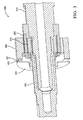
- FIG. 1 illustrates an exemplary embodiment of the magnetic torsion bar of an actuator assembly.
- FIGs. 2A-2D illustrate exemplary graphs of behavior of embodiments of magnetic torsion bars.
- FIG. 3 illustrates an alternate exemplary embodiment of a magnetic torsion bar of an actuator assembly.
- FIG. 4 illustrates another alternate exemplary embodiment of a magnetic torsion bar of an actuator assembly.
- FIG. 5 illustrates another alternate exemplary embodiment of a magnetic torsion bar of an actuator assembly.
- FIG. 6 illustrates another exemplary embodiment of a magnetic torsion bar of an actuator assembly.
- Power steering systems may incorporate a torsion bar in hydraulic and electric actuators.
- the torsion bar typically provides a means to measure driver torque by sensing the deflection of the torsion bar.
- the torsion bar also provides the necessary torque coupling between the driver the rest of the steering system, thus providing a desired tactile "feel" to the user.
- Hydraulic and electric actuators may be magnetically actuated.
- a magnetically actuated actuator includes a ring magnet and poles that rotate when a magnetic flux is induced.
- FIG. 1 illustrates the magnetic torsion bar assembly 200 of a typical electric or hydraulic steering system.
- the magnetic torsion bar assembly 200 includes a steering shaft 214 connected to a handwheel (not shown) and a ring magnet 209.
- the ring magnet 209 includes magnetic poles 208 and 210.
- Inner teeth 204 and outer teeth 206 are connected to an output shaft 212.
- the magnetic portion 200 includes 15 pairs of teeth, however other embodiments may include other teeth arrangements.
- a pair of teeth includes an inner tooth 204 and an outer tooth 206.
- the magnet 209 may be a single piece ring magnet with 15 pairs of poles.
- the magnetic pole 208 and 210 pairs may be fabricated using multiple magnets attached in a desirable pattern. Each pair of poles includes a north pole and a south pole.
- a driver input from a handwheel connected to the steering shaft 214 rotates the steering shaft 214.
- the steering shaft 214 rotates the ring magnet 209. Flux forces in the ring magnet 209 impart a torque on the inner teeth 204 and the outer teeth 206.
- the torque rotates the inner teeth 204 and the outer teeth 206 and rotates the connected output shaft 212.
- the assembly 200 include a mechanical torsion bar 218 disposed in a center cavity of the steering shaft 214.
- the torsion bar is connected to the output shaft 212 and the steering shaft 214.
- the torsion bar imparts a torque on the handwheel that provides a tactile response to the driver.
- the torsion bar ensures that the valve opening for a hydraulic power steering system is controlled as a function of the driver torque.
- the deflection of the torsion bar is usually sensed with an electrical device.
- One disadvantage of an actuator assembly that uses a torsion bar is that the fabrication of the actuator assembly may be costly. For example, the center of the valve body is machined to align with the center of the torsion bar and a center of the magnetic actuator portion.
- the actuator assembly is machined or assembled to high tolerances that result in costly production procedures and waste.
- the non-linear or variable stiffness characteristics are difficult to implement using a mechanical torsion bar.
- the assembly 200 and the additional embodiments described below may be more easily fabricated without a torsion bar 218. If the torsion bar 218 is removed, a new method for providing the function of a torsion bar 218 is desired.
- the assembly 200 allows the torque response of a torsion bar 218 to be imparted by the magnetic actuator portion.
- the assembly 200 may include the torsion bar 218 to supplement its behavior with non-linear or variable stiffness characteristics.
- the magnetic interaction between the ring magnet 209 and the inner teeth 204 and outer teeth 206 is designed to impart a torque response similar to the mechanical torsion bar of previous systems.
- the torque used to replicate a mechanical torsion bar is called an electromagnetic torsion bar.
- the mechanical torsion bar may be removed from the actuator. This simplifies the fabrication of the actuator.
- FIG. 2A illustrates a comparison of the torque induced by a mechanical torsion bar (Tbar) and the torque induced by an electromagnetic torsion bar.
- the EM torque curves represent the torque induced in rotating the magnetic actuator portion, and the Tbar torque curve represents the torque induced by a mechanical torsion bar.
- the range of motion of the torsion bar is limited to a maximum range of about +/- 4 degrees via the use of travel stops.
- the use of electromagnetic torque to approximate the torque induced by a mechanical torsion bar over this range effectively allows a mechanical torsion bar to be removed or supplemented using this device.
- FIG. 3 illustrates an exemplary embodiment of magnetic actuator portion 400 having an electromagnetic torsion bar.
- the magnetic actuator portion 400 is similar in structure and operation to the magnetic actuator portion 200 described above.
- Determining the torque applied to upper input shaft 214 described above is desirable.
- the use of a separate torque sensing unit is undesirable because it adds a component to the system increasing cost and the use of space.
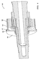
- FIG. 4 includes a magnetic sensor 407, an outer yoke portion 402, an inner yoke portion 411, and a plate portion 403.
- the plate portion 403 and the inner yoke portion 411 are connected to the shaft 412.
- the outer yoke portion 402 and the plate portion 411 define an airgap 405.
- the airgap 405 is a cavity that contains the magnetic sensor 407 that includes a magneto-sensitive element, such as, for example a Hall Effect sensor.
- the airgap 405 may contain a number of magneto-sensitive elements.
- the senor 407 detects a relative angular displacement between the ring magnet 209 and the teeth by sensing a change in flux as the ring magnet 209 rotates.
- the relative angular displacement may be converted to a torque value.
- the use of a magneto-sensitive element allows the torque to be determined without using a separate sensing unit.
- An advantage of the embodiment of FIG. 4 is that the packaging size of the actuator is reduced.
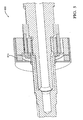
- FIG. 5 illustrates an embodiment of a magnetic actuator portion 500.
- the magnetic actuator portion 500 is similar to the magnetic actuator portion 400 described above.
- the magnetic actuator portion 500 includes an outer housing portion 502.
- the outer housing portion 502 remains stationary relative to the rotation of the magnetic and shaft portions of the magnetic actuator portion 500.
- the outer housing portion 502 includes an upper outer housing portion 511 and a lower outer housing portion 503 that partially define an airgap 505.
- the airgap provides a cavity for the position sensor 407 that operates as described above.
- the relative angular displacement may be converted to a torque value.
- a change in stiffness felt at the handwheel by a user is desirable as the user rotates a handwheel through a range of motion.
- a system may be designed to have a non-linear stiffness characteristic with a stiff tactile feel when the handwheel is centered during high-speed driving, and a more compliant tactile feel when steering at higher efforts off-center, typically encountered during parking and low speed maneuvers. This is accomplished by designing the shape of the curve in Figure 2A to a desired target stiffness.
- driving conditions such as vehicle speed.
- Variable stiffness as a function of driving conditions is complex to achieve using a mechanical torsion bar.
- the variable stiffness function may be incorporated into the magnetic actuator portion using a coil.
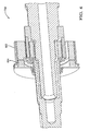
- FIG. 6 illustrates an exemplary embodiment of a magnetic actuator portion 600 that includes a coil 614.
- the magnetic actuator portion 600 is similar to the magnetic actuator portion 200 (of FIG. 1 ).
- the coil 614 induces a secondary field in the magnetic actuator portion 600.
- Figure 2C illustrates a behavior of the interaction force between the pole piece and the ring magnet (illustrated above).
- the coil When the coil is energized, it imparts an additional electromagnetic force between the pole piece and the ring magnet with the resulting response shown in Figure 2C as a function of current.
- the variable stiffness behavior of the system is realized between travel stops as shown in Figure 2D .
- the torque overlay behavior of the system is realized between travel stops as shown in Figure 2B .
- the magnetic torque created by the coil may be designed to produce a different effect by choosing a different operating point on the magnetic torque curve as shown in Figure 2C .
- the mechanical center is placed to be the same as the magnetic center of the plot in Figure 2C and thus realizes a variable torque overlay device between typical travel stops as shown in Figure 2B .
- the use of an electromagnetic torsion bar simplifies the application of torque overlay.
- the current command used to operate the actuator changes the stiffness of the actuator as felt by a user as the actuator rotates.
- the change in stiffness may be controlled by manipulating the cogging torque thereby varying the torque of the electromagnetic torsion bar.
- FIG. 6 illustrates an embodiment of a magnetic actuator portion 700 that includes the coil 614 (of FIG. 5 ) and the outer housing 502 (of FIG. 4 ).
- the magnetic actuator and torque sensing portion 700 is similar to the magnetic torsion bar and torque sensing portion 500 described above and uses the coil 614.
Landscapes
- Engineering & Computer Science (AREA)
- Physics & Mathematics (AREA)
- Chemical & Material Sciences (AREA)
- Combustion & Propulsion (AREA)
- Transportation (AREA)
- Mechanical Engineering (AREA)
- Electromagnetism (AREA)
- General Physics & Mathematics (AREA)
- Power Steering Mechanism (AREA)
- Steering Control In Accordance With Driving Conditions (AREA)
Abstract
Description
- Power steering systems in vehicles use actuators to provide assist and sometime include capabilities such as variable effort steering and torque overlay to provide a desired response in the systems.
- Many actuators use a torsion bar disposed within a valve to control the valve or other input measuring device as a function of torque, and to a provide tactile feedback to the driver at the hand wheel.
- The above described and other features are exemplified by the following Figures and Description in which actuators are disclosed that include an actuator assembly including, a polar assembly including an inner tooth and an outer tooth, and a magnet disposed between the inner tooth and the outer tooth, the magnet operative to interact with the polar assembly to induce an electromagnetic torsion bar operative to impart a torque on a first shaft connected to the magnet.
- Referring now to the Figures wherein like elements are numbered alike:
-
FIG. 1 illustrates an exemplary embodiment of the magnetic torsion bar of an actuator assembly. -
FIGs. 2A-2D illustrate exemplary graphs of behavior of embodiments of magnetic torsion bars. -
FIG. 3 illustrates an alternate exemplary embodiment of a magnetic torsion bar of an actuator assembly. -
FIG. 4 illustrates another alternate exemplary embodiment of a magnetic torsion bar of an actuator assembly. -
FIG. 5 illustrates another alternate exemplary embodiment of a magnetic torsion bar of an actuator assembly. -
FIG. 6 illustrates another exemplary embodiment of a magnetic torsion bar of an actuator assembly. - Power steering systems may incorporate a torsion bar in hydraulic and electric actuators. The torsion bar typically provides a means to measure driver torque by sensing the deflection of the torsion bar. In addition, the torsion bar also provides the necessary torque coupling between the driver the rest of the steering system, thus providing a desired tactile "feel" to the user. Hydraulic and electric actuators may be magnetically actuated. For example, a magnetically actuated actuator includes a ring magnet and poles that rotate when a magnetic flux is induced.
-
FIG. 1 illustrates the magnetictorsion bar assembly 200 of a typical electric or hydraulic steering system. The magnetictorsion bar assembly 200 includes asteering shaft 214 connected to a handwheel (not shown) and aring magnet 209. Thering magnet 209 includesmagnetic poles Inner teeth 204 andouter teeth 206 are connected to anoutput shaft 212. - The
magnetic portion 200 includes 15 pairs of teeth, however other embodiments may include other teeth arrangements. A pair of teeth includes aninner tooth 204 and anouter tooth 206. Themagnet 209 may be a single piece ring magnet with 15 pairs of poles. Alternatively, themagnetic pole - In operation, a driver input from a handwheel connected to the
steering shaft 214 rotates thesteering shaft 214. Thesteering shaft 214 rotates thering magnet 209. Flux forces in thering magnet 209 impart a torque on theinner teeth 204 and theouter teeth 206. The torque rotates theinner teeth 204 and theouter teeth 206 and rotates the connectedoutput shaft 212. - The
assembly 200 include amechanical torsion bar 218 disposed in a center cavity of thesteering shaft 214. The torsion bar is connected to theoutput shaft 212 and thesteering shaft 214. The torsion bar imparts a torque on the handwheel that provides a tactile response to the driver. In addition, the torsion bar ensures that the valve opening for a hydraulic power steering system is controlled as a function of the driver torque. In an electric power steering system, the deflection of the torsion bar is usually sensed with an electrical device. One disadvantage of an actuator assembly that uses a torsion bar is that the fabrication of the actuator assembly may be costly. For example, the center of the valve body is machined to align with the center of the torsion bar and a center of the magnetic actuator portion. The actuator assembly is machined or assembled to high tolerances that result in costly production procedures and waste. In certain applications, it may be desirable to have a non-linear or variable stiffness characteristic for improved steering feel and performance. The non-linear or variable stiffness characteristics are difficult to implement using a mechanical torsion bar. - The
assembly 200 and the additional embodiments described below may be more easily fabricated without atorsion bar 218. If thetorsion bar 218 is removed, a new method for providing the function of atorsion bar 218 is desired. Theassembly 200 allows the torque response of atorsion bar 218 to be imparted by the magnetic actuator portion. Alternatively, theassembly 200 may include thetorsion bar 218 to supplement its behavior with non-linear or variable stiffness characteristics. - The magnetic interaction between the
ring magnet 209 and theinner teeth 204 andouter teeth 206 is designed to impart a torque response similar to the mechanical torsion bar of previous systems. The torque used to replicate a mechanical torsion bar is called an electromagnetic torsion bar. - By using the electromagnetic torsion bar to impart a similar torque as the mechanical torsion bar, the mechanical torsion bar may be removed from the actuator. This simplifies the fabrication of the actuator.
-
FIG. 2A illustrates a comparison of the torque induced by a mechanical torsion bar (Tbar) and the torque induced by an electromagnetic torsion bar. The EM torque curves represent the torque induced in rotating the magnetic actuator portion, and the Tbar torque curve represents the torque induced by a mechanical torsion bar. - Typically, the range of motion of the torsion bar is limited to a maximum range of about +/- 4 degrees via the use of travel stops. Thus, the use of electromagnetic torque to approximate the torque induced by a mechanical torsion bar over this range effectively allows a mechanical torsion bar to be removed or supplemented using this device.
-
FIG. 3 illustrates an exemplary embodiment ofmagnetic actuator portion 400 having an electromagnetic torsion bar. Themagnetic actuator portion 400 is similar in structure and operation to themagnetic actuator portion 200 described above. - Determining the torque applied to
upper input shaft 214 described above is desirable. The use of a separate torque sensing unit is undesirable because it adds a component to the system increasing cost and the use of space. -
FIG. 4 includes amagnetic sensor 407, anouter yoke portion 402, aninner yoke portion 411, and aplate portion 403. Theplate portion 403 and theinner yoke portion 411 are connected to theshaft 412. Theouter yoke portion 402 and theplate portion 411 define anairgap 405. Theairgap 405 is a cavity that contains themagnetic sensor 407 that includes a magneto-sensitive element, such as, for example a Hall Effect sensor. Theairgap 405 may contain a number of magneto-sensitive elements. - In operation, the
sensor 407 detects a relative angular displacement between thering magnet 209 and the teeth by sensing a change in flux as thering magnet 209 rotates. The relative angular displacement may be converted to a torque value. The use of a magneto-sensitive element allows the torque to be determined without using a separate sensing unit. An advantage of the embodiment ofFIG. 4 is that the packaging size of the actuator is reduced. -
FIG. 5 illustrates an embodiment of amagnetic actuator portion 500. Themagnetic actuator portion 500 is similar to themagnetic actuator portion 400 described above. Themagnetic actuator portion 500 includes anouter housing portion 502. Theouter housing portion 502 remains stationary relative to the rotation of the magnetic and shaft portions of themagnetic actuator portion 500. Theouter housing portion 502 includes an upperouter housing portion 511 and a lowerouter housing portion 503 that partially define anairgap 505. The airgap provides a cavity for theposition sensor 407 that operates as described above. The relative angular displacement may be converted to a torque value. - In some steering systems a change in stiffness felt at the handwheel by a user is desirable as the user rotates a handwheel through a range of motion. For example, a system may be designed to have a non-linear stiffness characteristic with a stiff tactile feel when the handwheel is centered during high-speed driving, and a more compliant tactile feel when steering at higher efforts off-center, typically encountered during parking and low speed maneuvers. This is accomplished by designing the shape of the curve in
Figure 2A to a desired target stiffness. Alternatively, it may be desirable to have the stiffness variable with driving conditions such as vehicle speed. Variable stiffness as a function of driving conditions is complex to achieve using a mechanical torsion bar. However, the variable stiffness function may be incorporated into the magnetic actuator portion using a coil. -
FIG. 6 illustrates an exemplary embodiment of amagnetic actuator portion 600 that includes acoil 614. Themagnetic actuator portion 600 is similar to the magnetic actuator portion 200 (ofFIG. 1 ). Thecoil 614 induces a secondary field in themagnetic actuator portion 600. -
Figure 2C illustrates a behavior of the interaction force between the pole piece and the ring magnet (illustrated above). When the coil is energized, it imparts an additional electromagnetic force between the pole piece and the ring magnet with the resulting response shown inFigure 2C as a function of current. If operated with a mechanical center around the 6 degree angle the variable stiffness behavior of the system is realized between travel stops as shown inFigure 2D . If operated with a mechanical center around the 0 degree angle the torque overlay behavior of the system is realized between travel stops as shown inFigure 2B . - In some embodiments, it may be desirable to apply a torque on the torsion bar, for example to automate steering for parking assist in hydraulic systems. In this case, the magnetic torque created by the coil may be designed to produce a different effect by choosing a different operating point on the magnetic torque curve as shown in
Figure 2C . Here the mechanical center is placed to be the same as the magnetic center of the plot inFigure 2C and thus realizes a variable torque overlay device between typical travel stops as shown inFigure 2B . - The use of an electromagnetic torsion bar simplifies the application of torque overlay. The current command used to operate the actuator changes the stiffness of the actuator as felt by a user as the actuator rotates. The change in stiffness (variable stiffness) may be controlled by manipulating the cogging torque thereby varying the torque of the electromagnetic torsion bar.
-
FIG. 6 illustrates an embodiment of amagnetic actuator portion 700 that includes the coil 614 (ofFIG. 5 ) and the outer housing 502 (ofFIG. 4 ). The magnetic actuator andtorque sensing portion 700 is similar to the magnetic torsion bar andtorque sensing portion 500 described above and uses thecoil 614. - The technical effects and benefits of the system and methods described above allow cogging torque to effect a desired torque response of an actuator, a sensing of the torque, and the use of a torque overlay function and variable stiffness function..
- While the invention has been described with reference to exemplary embodiments, it will be understood by those of ordinary skill in the pertinent art that various changes may be made and equivalents may be substituted for the elements thereof without departing from the scope of the present disclosure. In addition, numerous modifications may be made to adapt the teachings of the disclosure to a particular object or situation without departing from the essential scope thereof. Therefore, it is intended that the Claims not be limited to the particular embodiments disclosed as the currently preferred best modes contemplated for carrying out the teachings herein, but that the Claims shall cover all embodiments falling within the true scope and spirit of the disclosure.
Claims (15)
- An actuator assembly including:a tooth assembly including an inner tooth and an outer tooth;a first shaft connected to the tooth assembly;a magnet disposed between the inner tooth and the outer tooth, the magnet operative to interact with the polar assembly to electromagnetically induce a function of a mechanical torsion bar; anda second shaft connected to the magnet.
- The actuator assembly of claim 1, wherein the actuator assembly further includes a coil to induce a secondary flux field that imparts a torque overlay between the first and the second shaft.
- The actuator assembly of claim 1, wherein the actuator assembly further includes a coil operative to induce a secondary flux field that varies the torsional stiffness between the first and the second shaft.
- The actuator assembly of claim 1, wherein the assembly further includes a mechanical torsion bar connected to the first shaft and the second shaft.
- The actuator assembly of claim 1, wherein the assembly further includes:an upper housing portion;a lower housing portion;an airgap partially defined by the upper housing portion and the lower housing portion; anda sensor disposed in the airgap operative to sense a position of the magnet relative to the polar assembly.
- The actuator assembly of claim 5, wherein the actuator assembly further includes a coil to induce a secondary flux field that imparts a torque overlay between the first and the second shaft.
- The actuator assembly of claim 5, wherein the sensor is a Hall Effect sensor.
- The actuator assembly of claim 5, wherein the assembly further includes a mechanical torsion bar connected to the first shaft and the second shaft.
- The magnet of claim 1, wherein the magnet includes multiple pole pairs.
- The magnet of claim 1, wherein the magnet is a ring magnet.
- The actuator assembly of claim 1, wherein the assembly further includes:an outer yoke portion;a plate portion;an airgap partially defined by the outer yoke portion and the plate portion; anda sensor disposed in the airgap operative to sense a position of the magnet relative to the polar assembly.
- The actuator assembly of claim 11, wherein the actuator assembly further includes a coil operative to induce a secondary flux field that varies the torsional stiffness between the first and the second shaft.
- The actuator assembly of claim 11, wherein the sensor is a magneto-sensitive element operative to sense a flux associated with the position of the magnet, and/or
wherein the assembly further includes a mechanical torsion bar connected to the first shaft and the second shaft, and/or
wherein the sensor is a Hall Effect sensor, and/or
wherein the magnet is a ring magnet. - A steering system including:an actuator assembly including:a tooth assembly including an inner tooth and an outer tooth;a first shaft connected to the tooth assembly;a magnet disposed between the inner tooth and the outer tooth, the magnet operative to interact with the polar assembly to electromagnetically induce a function of a mechanical torsion bar; anda second shaft connected to the magnet; anda hand wheel connected to the second shaft operative to receive a torque input from a user.
- The steering system of claim 14, wherein the actuator assembly further includes a coil to induce a secondary flux field that imparts a torque overlay between the first and the second shaft, and/or
wherein the actuator assembly further includes a coil operative to induce a secondary flux field that varies the torsional stiffness between the first and the second shaft, and/or
wherein the assembly further includes a mechanical torsion bar connected to the first shaft and the second shaft.
Priority Applications (1)
| Application Number | Priority Date | Filing Date | Title |
|---|---|---|---|
| PL09015433T PL2221237T3 (en) | 2008-12-12 | 2009-12-14 | Methods and systems involving electromagnetic torsion bars for vehicle power steering systems |
Applications Claiming Priority (1)
| Application Number | Priority Date | Filing Date | Title |
|---|---|---|---|
| US12/333,802 US8528686B2 (en) | 2008-12-12 | 2008-12-12 | Methods and systems involving electromagnetic torsion bars |
Publications (2)
| Publication Number | Publication Date |
|---|---|
| EP2221237A1 true EP2221237A1 (en) | 2010-08-25 |
| EP2221237B1 EP2221237B1 (en) | 2013-07-24 |
Family
ID=41531768
Family Applications (1)
| Application Number | Title | Priority Date | Filing Date |
|---|---|---|---|
| EP09015433.7A Not-in-force EP2221237B1 (en) | 2008-12-12 | 2009-12-14 | Methods and systems involving electromagnetic torsion bars for vehicle power steering systems |
Country Status (3)
| Country | Link |
|---|---|
| US (1) | US8528686B2 (en) |
| EP (1) | EP2221237B1 (en) |
| PL (1) | PL2221237T3 (en) |
Cited By (1)
| Publication number | Priority date | Publication date | Assignee | Title |
|---|---|---|---|---|
| US10160483B2 (en) | 2013-10-29 | 2018-12-25 | Steering Solutions Ip Holding Corporation | Retainer assembly for power steering system |
Families Citing this family (9)
| Publication number | Priority date | Publication date | Assignee | Title |
|---|---|---|---|---|
| EP2006982B1 (en) * | 2007-06-21 | 2020-04-01 | GM Global Technology Operations LLC | Methods of making torque overlay actuators |
| DE102014111624B4 (en) | 2013-08-15 | 2024-02-22 | Steering Solutions IP Holding Corp. | Assembly for providing steering assistance to a vehicle |
| WO2015133167A1 (en) * | 2014-03-05 | 2015-09-11 | 日本精工株式会社 | Electric power steering device and method for assembling same |
| CN105829190B (en) * | 2014-03-05 | 2018-03-16 | 日本精工株式会社 | Electric steering-assisted device and its assemble method |
| DE102014009892B4 (en) * | 2014-07-04 | 2018-05-30 | gomtec GmbH | Drive unit with magnetic interface |
| CN207552093U (en) * | 2016-07-28 | 2018-06-29 | 荷兰联合利华有限公司 | The online device that purifying hot water is provided |
| CN106411100B (en) * | 2016-10-28 | 2019-05-10 | 中国石油大学(华东) | A coaxial magnetic gear with static excitation ring |
| CN110115522B (en) * | 2018-02-06 | 2022-03-01 | 佛山市顺德区美的电热电器制造有限公司 | Magnetic transmission disc, magnetic transmission assembly, cutter assembly and food processor |
| MX2022000509A (en) * | 2019-07-12 | 2022-02-10 | R H Sheppard Co Inc | Coupled steering gear shaft. |
Citations (1)
| Publication number | Priority date | Publication date | Assignee | Title |
|---|---|---|---|---|
| DE102005011196A1 (en) * | 2005-03-09 | 2006-09-14 | Robert Bosch Gmbh | Steering column torque detecting sensor arrangement for motor vehicle, has magnetic circuit with flux rings designed as ferromagnetic rings, such that sensor unit and wheel are arranged between inner flux ring and outer flux ring |
Family Cites Families (7)
| Publication number | Priority date | Publication date | Assignee | Title |
|---|---|---|---|---|
| DE2337015C2 (en) * | 1973-07-20 | 1983-07-14 | Robert Bosch Gmbh, 7000 Stuttgart | Device for the optical scanning of a plate rotating about a vertical axis of rotation |
| US5070956A (en) * | 1990-10-09 | 1991-12-10 | General Motors Corporation | Electromagnetic control apparatus for varying the driver steering effort of a hydraulic power steering system |
| US5454439A (en) * | 1994-08-29 | 1995-10-03 | General Motors Corporation | Power steering gear for motor vehicle |
| DE69839927D1 (en) * | 1997-10-13 | 2008-10-02 | Matsushita Electric Industrial Co Ltd | Motor with inner permanent magnet rotor |
| FR2824910B1 (en) * | 2001-05-18 | 2005-05-13 | Denso Corp | TORQUE SENSOR AND POWER ASSISTED STEERING SYSTEM EMPLOYING THIS SENSOR |
| US6863614B2 (en) * | 2003-05-01 | 2005-03-08 | Visteon Global Technologies, Inc. | Shunted collarless torsion shaft for electronic power-assisted steering systems |
| US7364006B2 (en) * | 2005-05-05 | 2008-04-29 | Delphi Technologies, Inc. | Steering system with leads and pulls compensation |
-
2008
- 2008-12-12 US US12/333,802 patent/US8528686B2/en not_active Expired - Fee Related
-
2009
- 2009-12-14 EP EP09015433.7A patent/EP2221237B1/en not_active Not-in-force
- 2009-12-14 PL PL09015433T patent/PL2221237T3/en unknown
Patent Citations (1)
| Publication number | Priority date | Publication date | Assignee | Title |
|---|---|---|---|---|
| DE102005011196A1 (en) * | 2005-03-09 | 2006-09-14 | Robert Bosch Gmbh | Steering column torque detecting sensor arrangement for motor vehicle, has magnetic circuit with flux rings designed as ferromagnetic rings, such that sensor unit and wheel are arranged between inner flux ring and outer flux ring |
Cited By (1)
| Publication number | Priority date | Publication date | Assignee | Title |
|---|---|---|---|---|
| US10160483B2 (en) | 2013-10-29 | 2018-12-25 | Steering Solutions Ip Holding Corporation | Retainer assembly for power steering system |
Also Published As
| Publication number | Publication date |
|---|---|
| US20100147619A1 (en) | 2010-06-17 |
| EP2221237B1 (en) | 2013-07-24 |
| PL2221237T3 (en) | 2014-03-31 |
| US8528686B2 (en) | 2013-09-10 |
Similar Documents
| Publication | Publication Date | Title |
|---|---|---|
| EP2221237B1 (en) | Methods and systems involving electromagnetic torsion bars for vehicle power steering systems | |
| EP1291264B1 (en) | Apparatus and method for detecting absolute position | |
| EP1906510A2 (en) | Brushless motor and electric power steering apparatus incorporating the same | |
| JP2024507085A (en) | Active/semi-active steer-by-wire systems and methods | |
| EP1810910B1 (en) | Motor and power steering apparatus | |
| JP6327456B2 (en) | Torque sensor and electric power steering device | |
| US11479290B2 (en) | Steering system having a reluctance brake | |
| CN113168204B (en) | Adjustable force devices, electric motors and door closer mechanisms | |
| WO2001056005A9 (en) | An actuation device having multiple degrees of freedom of movement and reduced inertia | |
| WO2017204099A1 (en) | Electric linear motion actuator | |
| US6967422B2 (en) | Rotary actuator | |
| JP2013005659A (en) | Electric motor | |
| US20070107974A1 (en) | Steering device for vehicle | |
| EP1971010A2 (en) | Brush-less motor and electric power steering device having brush-less motor | |
| JPH08228466A (en) | Actuator | |
| US20240109582A1 (en) | Active/semi-active steer-by-wire system and method | |
| JPH05133706A (en) | Phase sensing actuator | |
| US6847177B1 (en) | Apparatus and method for determining rotor lamination shifts in an electric motor | |
| KR20220060849A (en) | Steering combined torque sensor | |
| CN114516363A (en) | Steering apparatus and method | |
| US20020135253A1 (en) | Rotor assembly for variable torque constant brushless motors | |
| JP2022079087A (en) | Rotation angle detector | |
| Ermert | Electromechanical actuator concept for the controlled and direct actuation of a hydraulic main stage | |
| CN112421912A (en) | A motor and a steer-by-wire steering wheel actuator | |
| GB2631719A (en) | An electric motor and handwheel actuator assembly incorporating a motor |
Legal Events
| Date | Code | Title | Description |
|---|---|---|---|
| PUAI | Public reference made under article 153(3) epc to a published international application that has entered the european phase |
Free format text: ORIGINAL CODE: 0009012 |
|
| AK | Designated contracting states |
Kind code of ref document: A1 Designated state(s): AT BE BG CH CY CZ DE DK EE ES FI FR GB GR HR HU IE IS IT LI LT LU LV MC MK MT NL NO PL PT RO SE SI SK SM TR |
|
| AX | Request for extension of the european patent |
Extension state: AL BA RS |
|
| 17P | Request for examination filed |
Effective date: 20110120 |
|
| RAP1 | Party data changed (applicant data changed or rights of an application transferred) |
Owner name: GM GLOBAL TECHNOLOGY OPERATIONS LLC |
|
| 17Q | First examination report despatched |
Effective date: 20120912 |
|
| RAP1 | Party data changed (applicant data changed or rights of an application transferred) |
Owner name: STEERING SOLUTIONS IP HOLDING CORPORATION Owner name: GM GLOBAL TECHNOLOGY OPERATIONS LLC |
|
| REG | Reference to a national code |
Ref country code: DE Ref legal event code: R079 Ref document number: 602009017339 Country of ref document: DE Free format text: PREVIOUS MAIN CLASS: B62D0006100000 Ipc: B62D0005083000 |
|
| GRAP | Despatch of communication of intention to grant a patent |
Free format text: ORIGINAL CODE: EPIDOSNIGR1 |
|
| RIC1 | Information provided on ipc code assigned before grant |
Ipc: B62D 5/083 20060101AFI20130130BHEP |
|
| GRAS | Grant fee paid |
Free format text: ORIGINAL CODE: EPIDOSNIGR3 |
|
| GRAA | (expected) grant |
Free format text: ORIGINAL CODE: 0009210 |
|
| AK | Designated contracting states |
Kind code of ref document: B1 Designated state(s): AT BE BG CH CY CZ DE DK EE ES FI FR GB GR HR HU IE IS IT LI LT LU LV MC MK MT NL NO PL PT RO SE SI SK SM TR |
|
| REG | Reference to a national code |
Ref country code: GB Ref legal event code: FG4D |
|
| REG | Reference to a national code |
Ref country code: CH Ref legal event code: EP |
|
| REG | Reference to a national code |
Ref country code: AT Ref legal event code: REF Ref document number: 623230 Country of ref document: AT Kind code of ref document: T Effective date: 20130815 |
|
| REG | Reference to a national code |
Ref country code: IE Ref legal event code: FG4D |
|
| REG | Reference to a national code |
Ref country code: DE Ref legal event code: R096 Ref document number: 602009017339 Country of ref document: DE Effective date: 20130919 |
|
| REG | Reference to a national code |
Ref country code: AT Ref legal event code: MK05 Ref document number: 623230 Country of ref document: AT Kind code of ref document: T Effective date: 20130724 |
|
| REG | Reference to a national code |
Ref country code: NL Ref legal event code: VDEP Effective date: 20130724 |
|
| REG | Reference to a national code |
Ref country code: LT Ref legal event code: MG4D |
|
| PG25 | Lapsed in a contracting state [announced via postgrant information from national office to epo] |
Ref country code: CY Free format text: LAPSE BECAUSE OF FAILURE TO SUBMIT A TRANSLATION OF THE DESCRIPTION OR TO PAY THE FEE WITHIN THE PRESCRIBED TIME-LIMIT Effective date: 20130904 Ref country code: IS Free format text: LAPSE BECAUSE OF FAILURE TO SUBMIT A TRANSLATION OF THE DESCRIPTION OR TO PAY THE FEE WITHIN THE PRESCRIBED TIME-LIMIT Effective date: 20131124 Ref country code: AT Free format text: LAPSE BECAUSE OF FAILURE TO SUBMIT A TRANSLATION OF THE DESCRIPTION OR TO PAY THE FEE WITHIN THE PRESCRIBED TIME-LIMIT Effective date: 20130724 Ref country code: HR Free format text: LAPSE BECAUSE OF FAILURE TO SUBMIT A TRANSLATION OF THE DESCRIPTION OR TO PAY THE FEE WITHIN THE PRESCRIBED TIME-LIMIT Effective date: 20130724 Ref country code: NO Free format text: LAPSE BECAUSE OF FAILURE TO SUBMIT A TRANSLATION OF THE DESCRIPTION OR TO PAY THE FEE WITHIN THE PRESCRIBED TIME-LIMIT Effective date: 20131024 Ref country code: PT Free format text: LAPSE BECAUSE OF FAILURE TO SUBMIT A TRANSLATION OF THE DESCRIPTION OR TO PAY THE FEE WITHIN THE PRESCRIBED TIME-LIMIT Effective date: 20131125 Ref country code: LT Free format text: LAPSE BECAUSE OF FAILURE TO SUBMIT A TRANSLATION OF THE DESCRIPTION OR TO PAY THE FEE WITHIN THE PRESCRIBED TIME-LIMIT Effective date: 20130724 Ref country code: BE Free format text: LAPSE BECAUSE OF FAILURE TO SUBMIT A TRANSLATION OF THE DESCRIPTION OR TO PAY THE FEE WITHIN THE PRESCRIBED TIME-LIMIT Effective date: 20130724 Ref country code: SE Free format text: LAPSE BECAUSE OF FAILURE TO SUBMIT A TRANSLATION OF THE DESCRIPTION OR TO PAY THE FEE WITHIN THE PRESCRIBED TIME-LIMIT Effective date: 20130724 |
|
| PGFP | Annual fee paid to national office [announced via postgrant information from national office to epo] |
Ref country code: DE Payment date: 20131230 Year of fee payment: 5 |
|
| PG25 | Lapsed in a contracting state [announced via postgrant information from national office to epo] |
Ref country code: FI Free format text: LAPSE BECAUSE OF FAILURE TO SUBMIT A TRANSLATION OF THE DESCRIPTION OR TO PAY THE FEE WITHIN THE PRESCRIBED TIME-LIMIT Effective date: 20130724 Ref country code: SI Free format text: LAPSE BECAUSE OF FAILURE TO SUBMIT A TRANSLATION OF THE DESCRIPTION OR TO PAY THE FEE WITHIN THE PRESCRIBED TIME-LIMIT Effective date: 20130724 Ref country code: GR Free format text: LAPSE BECAUSE OF FAILURE TO SUBMIT A TRANSLATION OF THE DESCRIPTION OR TO PAY THE FEE WITHIN THE PRESCRIBED TIME-LIMIT Effective date: 20131025 Ref country code: NL Free format text: LAPSE BECAUSE OF FAILURE TO SUBMIT A TRANSLATION OF THE DESCRIPTION OR TO PAY THE FEE WITHIN THE PRESCRIBED TIME-LIMIT Effective date: 20130724 Ref country code: LV Free format text: LAPSE BECAUSE OF FAILURE TO SUBMIT A TRANSLATION OF THE DESCRIPTION OR TO PAY THE FEE WITHIN THE PRESCRIBED TIME-LIMIT Effective date: 20130724 |
|
| PG25 | Lapsed in a contracting state [announced via postgrant information from national office to epo] |
Ref country code: CY Free format text: LAPSE BECAUSE OF FAILURE TO SUBMIT A TRANSLATION OF THE DESCRIPTION OR TO PAY THE FEE WITHIN THE PRESCRIBED TIME-LIMIT Effective date: 20130724 |
|
| PG25 | Lapsed in a contracting state [announced via postgrant information from national office to epo] |
Ref country code: SK Free format text: LAPSE BECAUSE OF FAILURE TO SUBMIT A TRANSLATION OF THE DESCRIPTION OR TO PAY THE FEE WITHIN THE PRESCRIBED TIME-LIMIT Effective date: 20130724 Ref country code: EE Free format text: LAPSE BECAUSE OF FAILURE TO SUBMIT A TRANSLATION OF THE DESCRIPTION OR TO PAY THE FEE WITHIN THE PRESCRIBED TIME-LIMIT Effective date: 20130724 Ref country code: DK Free format text: LAPSE BECAUSE OF FAILURE TO SUBMIT A TRANSLATION OF THE DESCRIPTION OR TO PAY THE FEE WITHIN THE PRESCRIBED TIME-LIMIT Effective date: 20130724 Ref country code: RO Free format text: LAPSE BECAUSE OF FAILURE TO SUBMIT A TRANSLATION OF THE DESCRIPTION OR TO PAY THE FEE WITHIN THE PRESCRIBED TIME-LIMIT Effective date: 20130724 Ref country code: CZ Free format text: LAPSE BECAUSE OF FAILURE TO SUBMIT A TRANSLATION OF THE DESCRIPTION OR TO PAY THE FEE WITHIN THE PRESCRIBED TIME-LIMIT Effective date: 20130724 |
|
| PG25 | Lapsed in a contracting state [announced via postgrant information from national office to epo] |
Ref country code: ES Free format text: LAPSE BECAUSE OF FAILURE TO SUBMIT A TRANSLATION OF THE DESCRIPTION OR TO PAY THE FEE WITHIN THE PRESCRIBED TIME-LIMIT Effective date: 20130724 Ref country code: IT Free format text: LAPSE BECAUSE OF FAILURE TO SUBMIT A TRANSLATION OF THE DESCRIPTION OR TO PAY THE FEE WITHIN THE PRESCRIBED TIME-LIMIT Effective date: 20130724 |
|
| PGFP | Annual fee paid to national office [announced via postgrant information from national office to epo] |
Ref country code: FR Payment date: 20140220 Year of fee payment: 5 |
|
| PLBE | No opposition filed within time limit |
Free format text: ORIGINAL CODE: 0009261 |
|
| STAA | Information on the status of an ep patent application or granted ep patent |
Free format text: STATUS: NO OPPOSITION FILED WITHIN TIME LIMIT |
|
| 26N | No opposition filed |
Effective date: 20140425 |
|
| REG | Reference to a national code |
Ref country code: CH Ref legal event code: PL |
|
| REG | Reference to a national code |
Ref country code: DE Ref legal event code: R097 Ref document number: 602009017339 Country of ref document: DE Effective date: 20140425 |
|
| GBPC | Gb: european patent ceased through non-payment of renewal fee |
Effective date: 20131214 |
|
| PG25 | Lapsed in a contracting state [announced via postgrant information from national office to epo] |
Ref country code: LU Free format text: LAPSE BECAUSE OF FAILURE TO SUBMIT A TRANSLATION OF THE DESCRIPTION OR TO PAY THE FEE WITHIN THE PRESCRIBED TIME-LIMIT Effective date: 20131214 Ref country code: MC Free format text: LAPSE BECAUSE OF FAILURE TO SUBMIT A TRANSLATION OF THE DESCRIPTION OR TO PAY THE FEE WITHIN THE PRESCRIBED TIME-LIMIT Effective date: 20130724 |
|
| REG | Reference to a national code |
Ref country code: IE Ref legal event code: MM4A |
|
| PG25 | Lapsed in a contracting state [announced via postgrant information from national office to epo] |
Ref country code: IE Free format text: LAPSE BECAUSE OF NON-PAYMENT OF DUE FEES Effective date: 20131214 Ref country code: CH Free format text: LAPSE BECAUSE OF NON-PAYMENT OF DUE FEES Effective date: 20131231 Ref country code: LI Free format text: LAPSE BECAUSE OF NON-PAYMENT OF DUE FEES Effective date: 20131231 |
|
| PG25 | Lapsed in a contracting state [announced via postgrant information from national office to epo] |
Ref country code: GB Free format text: LAPSE BECAUSE OF NON-PAYMENT OF DUE FEES Effective date: 20131214 |
|
| PGFP | Annual fee paid to national office [announced via postgrant information from national office to epo] |
Ref country code: PL Payment date: 20131218 Year of fee payment: 5 |
|
| PG25 | Lapsed in a contracting state [announced via postgrant information from national office to epo] |
Ref country code: SM Free format text: LAPSE BECAUSE OF FAILURE TO SUBMIT A TRANSLATION OF THE DESCRIPTION OR TO PAY THE FEE WITHIN THE PRESCRIBED TIME-LIMIT Effective date: 20130724 |
|
| PG25 | Lapsed in a contracting state [announced via postgrant information from national office to epo] |
Ref country code: TR Free format text: LAPSE BECAUSE OF FAILURE TO SUBMIT A TRANSLATION OF THE DESCRIPTION OR TO PAY THE FEE WITHIN THE PRESCRIBED TIME-LIMIT Effective date: 20130724 |
|
| REG | Reference to a national code |
Ref country code: DE Ref legal event code: R119 Ref document number: 602009017339 Country of ref document: DE |
|
| PG25 | Lapsed in a contracting state [announced via postgrant information from national office to epo] |
Ref country code: MK Free format text: LAPSE BECAUSE OF FAILURE TO SUBMIT A TRANSLATION OF THE DESCRIPTION OR TO PAY THE FEE WITHIN THE PRESCRIBED TIME-LIMIT Effective date: 20130724 Ref country code: BG Free format text: LAPSE BECAUSE OF FAILURE TO SUBMIT A TRANSLATION OF THE DESCRIPTION OR TO PAY THE FEE WITHIN THE PRESCRIBED TIME-LIMIT Effective date: 20130724 Ref country code: HU Free format text: LAPSE BECAUSE OF FAILURE TO SUBMIT A TRANSLATION OF THE DESCRIPTION OR TO PAY THE FEE WITHIN THE PRESCRIBED TIME-LIMIT; INVALID AB INITIO Effective date: 20091214 |
|
| PG25 | Lapsed in a contracting state [announced via postgrant information from national office to epo] |
Ref country code: MT Free format text: LAPSE BECAUSE OF FAILURE TO SUBMIT A TRANSLATION OF THE DESCRIPTION OR TO PAY THE FEE WITHIN THE PRESCRIBED TIME-LIMIT Effective date: 20130724 |
|
| REG | Reference to a national code |
Ref country code: FR Ref legal event code: ST Effective date: 20150831 |
|
| PG25 | Lapsed in a contracting state [announced via postgrant information from national office to epo] |
Ref country code: DE Free format text: LAPSE BECAUSE OF NON-PAYMENT OF DUE FEES Effective date: 20150701 |
|
| PG25 | Lapsed in a contracting state [announced via postgrant information from national office to epo] |
Ref country code: FR Free format text: LAPSE BECAUSE OF NON-PAYMENT OF DUE FEES Effective date: 20141231 |
|
| PG25 | Lapsed in a contracting state [announced via postgrant information from national office to epo] |
Ref country code: PL Free format text: LAPSE BECAUSE OF NON-PAYMENT OF DUE FEES Effective date: 20141214 |