EP2221216A1 - Back cover and method of assembling back cover - Google Patents
Back cover and method of assembling back cover Download PDFInfo
- Publication number
- EP2221216A1 EP2221216A1 EP10153956A EP10153956A EP2221216A1 EP 2221216 A1 EP2221216 A1 EP 2221216A1 EP 10153956 A EP10153956 A EP 10153956A EP 10153956 A EP10153956 A EP 10153956A EP 2221216 A1 EP2221216 A1 EP 2221216A1
- Authority
- EP
- European Patent Office
- Prior art keywords
- cover
- main body
- case member
- back cover
- cover main
- Prior art date
- Legal status (The legal status is an assumption and is not a legal conclusion. Google has not performed a legal analysis and makes no representation as to the accuracy of the status listed.)
- Withdrawn
Links
- 238000000034 method Methods 0.000 title claims description 8
- 238000003780 insertion Methods 0.000 claims description 9
- 230000037431 insertion Effects 0.000 claims description 9
- 239000007769 metal material Substances 0.000 claims description 9
- 239000000463 material Substances 0.000 claims description 6
- 239000011347 resin Substances 0.000 claims description 6
- 229920005989 resin Polymers 0.000 claims description 6
- 230000000630 rising effect Effects 0.000 claims description 6
- 238000003466 welding Methods 0.000 claims description 4
- 230000000149 penetrating effect Effects 0.000 claims description 2
- 238000005286 illumination Methods 0.000 description 18
- 230000006872 improvement Effects 0.000 description 13
- XLYOFNOQVPJJNP-UHFFFAOYSA-N water Substances O XLYOFNOQVPJJNP-UHFFFAOYSA-N 0.000 description 9
- 239000000853 adhesive Substances 0.000 description 6
- 230000001070 adhesive effect Effects 0.000 description 6
- 238000007789 sealing Methods 0.000 description 6
- 239000007858 starting material Substances 0.000 description 6
- 230000008595 infiltration Effects 0.000 description 4
- 238000001764 infiltration Methods 0.000 description 4
- 238000000465 moulding Methods 0.000 description 4
- 239000004020 conductor Substances 0.000 description 2
- 230000004048 modification Effects 0.000 description 2
- 238000012986 modification Methods 0.000 description 2
- 230000009467 reduction Effects 0.000 description 2
- 230000002159 abnormal effect Effects 0.000 description 1
- 230000008859 change Effects 0.000 description 1
- 238000006243 chemical reaction Methods 0.000 description 1
- 238000010586 diagram Methods 0.000 description 1
- 230000000694 effects Effects 0.000 description 1
- 239000012811 non-conductive material Substances 0.000 description 1
- 230000005855 radiation Effects 0.000 description 1
- 239000004065 semiconductor Substances 0.000 description 1
- 230000001052 transient effect Effects 0.000 description 1
- 230000003245 working effect Effects 0.000 description 1
Images



Classifications
-
- B—PERFORMING OPERATIONS; TRANSPORTING
- B60—VEHICLES IN GENERAL
- B60Q—ARRANGEMENT OF SIGNALLING OR LIGHTING DEVICES, THE MOUNTING OR SUPPORTING THEREOF OR CIRCUITS THEREFOR, FOR VEHICLES IN GENERAL
- B60Q1/00—Arrangement of optical signalling or lighting devices, the mounting or supporting thereof or circuits therefor
- B60Q1/0088—Details of electrical connections
- B60Q1/0094—Arrangement of electronic circuits separated from the light source, e.g. mounting of housings for starter circuits for discharge lamps
-
- B—PERFORMING OPERATIONS; TRANSPORTING
- B60—VEHICLES IN GENERAL
- B60Q—ARRANGEMENT OF SIGNALLING OR LIGHTING DEVICES, THE MOUNTING OR SUPPORTING THEREOF OR CIRCUITS THEREFOR, FOR VEHICLES IN GENERAL
- B60Q1/00—Arrangement of optical signalling or lighting devices, the mounting or supporting thereof or circuits therefor
- B60Q1/0064—Arrangement of optical signalling or lighting devices, the mounting or supporting thereof or circuits therefor with provision for maintenance, e.g. changing the light bulb
- B60Q1/007—Arrangement of optical signalling or lighting devices, the mounting or supporting thereof or circuits therefor with provision for maintenance, e.g. changing the light bulb via a removable cap
-
- F—MECHANICAL ENGINEERING; LIGHTING; HEATING; WEAPONS; BLASTING
- F21—LIGHTING
- F21S—NON-PORTABLE LIGHTING DEVICES; SYSTEMS THEREOF; VEHICLE LIGHTING DEVICES SPECIALLY ADAPTED FOR VEHICLE EXTERIORS
- F21S45/00—Arrangements within vehicle lighting devices specially adapted for vehicle exteriors, for purposes other than emission or distribution of light
- F21S45/40—Cooling of lighting devices
- F21S45/47—Passive cooling, e.g. using fins, thermal conductive elements or openings
- F21S45/48—Passive cooling, e.g. using fins, thermal conductive elements or openings with means for conducting heat from the inside to the outside of the lighting devices, e.g. with fins on the outer surface of the lighting device
-
- Y—GENERAL TAGGING OF NEW TECHNOLOGICAL DEVELOPMENTS; GENERAL TAGGING OF CROSS-SECTIONAL TECHNOLOGIES SPANNING OVER SEVERAL SECTIONS OF THE IPC; TECHNICAL SUBJECTS COVERED BY FORMER USPC CROSS-REFERENCE ART COLLECTIONS [XRACs] AND DIGESTS
- Y10—TECHNICAL SUBJECTS COVERED BY FORMER USPC
- Y10T—TECHNICAL SUBJECTS COVERED BY FORMER US CLASSIFICATION
- Y10T29/00—Metal working
- Y10T29/49—Method of mechanical manufacture
- Y10T29/49002—Electrical device making
Definitions
- the present invention relates to a back cover and a method of assembling back cover.
- the invention relates more particularly to a technical field in which a cover main body and a case member are connected together by an elongated seal projection which is bonded in such a state that the projection is fitted in a seal groove so as to realize an improvement in mounting strength with which the case member is mounted on the case main body as well as an improvement in waterproofness therebetween.
- a light source and an illumination circuit (a ballast) for driving the light source are disposed in a lamp chamber defined by a front cover and a lamp body (for example, refer to JP-A-2008-277008 ).
- a vehicle lamp described in JP-A-2008-277008 has a cover main body which is formed from a resin material and a heat dissipating member which is formed of a metallic material and functions as a case member, and a heat dissipating member mounting portion formed into a frame-like shape is provided on the cover main body.
- the heat dissipating member is fitted inside the heat dissipating member mounting portion and is mounted on the cover main body by an outer circumferential portion thereof being bonded, for example.
- One or more embodiments of the present invention provide a back cover and a back cover assembling method in which mounting strength of a case member to a case main body is improved and waterproofness of a lamp chamber is also improved.
- a back cover 16 to be attached to a cover mounting portion 5 of a vehicle lamp 1 in which a light source 9 is disposed in a lamp chamber 4 defined by a lamp body 2 on which said cover mounting portion 5 having a mounting opening 5a is provided at a rear end portion of the lamp body 2 and a front cover 3 which covers a front of the lamp body 2, the back cover 16 is provided with: a cover main body 19 formed from a resin material and including a first fitting portion 21 provided on a front end side of the cover main body 19 and adapted to fit in the cover mounting portion 5 and a second fitting portion 24 provided on a rear end side of the cover main body 19; a connection terminal 20 formed of a metallic material and partially embedded in the cover main body 19 so as to be integrally formed with the cover main body 19; a metallic case member 18 fitted in the second fitting portion 24 and including a mounting recess portion 18a made to open forwards; a circuit board 29, 30 disposed within the mounting recess portion 18a
- the back cover may further include a rising wall portion 28 provided on an outer circumferential side of the connector frame portion 25 and covering at least a part of a circumference of the connector frame portion 25.
- the hands of an assembler or other surrounding objects are never brought into contact with the connector frame portion and the connector terminal portion which is positioned in the interior of the connector frame portion when the back cover is mounted on the cover mounting portion of the lamp body or the vehicle lamp is mounted on a vehicle body, thereby making it possible to prevent any damage to the connector frame portion and the connector terminal portion.
- the back cover may further include an insertion hole 23e formed in the cover main body 19 and penetrating through the cover main body 19 in a front-rear direction; a screw inserting hole 20e formed in the connection terminal 20 and positioned in association with the insertion hole 23e; a screwing hole 18e formed in the case member 18 and positioned in association with the insertion hole 23e; and a metallic shield plate 33 adapted to cover the connection terminal 20 from a front thereof.
- the shield plate 33 may be fixed to the case member 18 by a screw 100 which is inserted through the screw inserting hole 20e and the insertion hole 23e to be screwed into the screwing hole 18e.
- the back cover may further include a component disposing portion 23b provided in the cover member 19; and an electronic component 26 having a lead 26a and disposed in the component disposing portion 23b.
- the lead 26a of the electronic component 26 may be connected to the connection terminal 20 by welding.
- the back cover may further include a positioning hole 23d formed in the cover main body 19; and a positioning pin 18f provided on the case member 18 and inserted in the positioning hole 23d.
- the back cover may further include a chip component 31 mounted on one surface of the circuit board 29, 30.
- the other surface of the circuit board 29, 30 may be formed into a flat plane.
- the circuit board 29, 30 may be mounted on the case member 18, and the other surface of the circuit board 29, 30 is in surface contact with the case member 18.
- the heat transfer coefficient of heat generated in the circuit board to the case member is high, thereby making it possible to realize an improvement in heat dissipating performance of the back cover.
- the back cover may further include a plurality of engagement projecting portions 21a provided at a front end portion of the first fitting portion 21 so as to be positioned spaced apart from each other in a circumferential direction; and a restricting projecting portion 21b projecting forwards and provided at least one of the plurality of engagement projecting portions 21a.
- the cover mounting portion 5 of the lamp body 2 may include a plurality of inserting cutouts 6a into which the plurality of engagement projecting portions 21a are inserted individually from a rear thereof and a plurality of engagement portions 6 with which the plurality of engagement projecting portions 21a are brought into engagement when the cover main body 19 is rotated in the circumferential direction in such a state that the plurality of engagement projecting portions 21a are inserted individually into the plurality of inserting cutouts 6a from the rear thereof.
- the back cover can be prevented from being mounted on the cover mounting portion in an incomplete condition when the back cover is oriented improperly towards the cover mounting portion.
- the back cover in a back cover to be attached to a cover mounting portion 5 of a vehicle lamp in which a light source 9 is disposed in a lamp chamber 4 defined by a lamp body 2 on which said cover mounting portion 5 having a mounting opening 5a is provided at a rear end portion of the lamp body 2 and a front cover 3 which covers a front of the lamp body 2, the back cover is manufactured by: providing a seal groove 27 on one of a cover main body 19 and a metallic case member 18 to open forwards or rearwards, wherein said cover main body 19 is integrally molded with a connection terminal 20 made of a metallic material in such a state that the connection terminal 20 is mostly embedded in the cover main body 19, and wherein a circuit board 29, 30 is mounted on said case member 18; providing an elongated seal projection 18b on the other of said cover main body 19 and said case member 18 to project rearwards or forwards; butting and fitting the seal groove 27 and the elongated seal projection 18b in a front
- a vehicle lamp that is, a vehicle headlamp 1, for example, is disposed at each of both left- and right-hand end portions of a front end portion of a vehicle body.
- the vehicle headlamp 1 includes a lamp body 2 having a recess portion which is made to open forwards and a front cover 3 which closes a front opening of the lamp body 2, and an interior space defined by the lamp body 2 and the front cover 3 is defined as a lamp chamber 4.
- the cover mounting portion 5 has a mounting opening 5a which penetrates therethrough in a front-rear direction.
- Engagement portions 6, 6, ... are provided on an inner surface of the cover mounting portion 5.
- the engagement portions 6, 6, ... are provided so as to be spaced apart in a circumferential direction and are formed so as to extend in the circumferential direction while being caused to project radially inwards from the inner surface of the cover mounting portion 5.
- Spaces between the engagement portions 6, 6, ... are defined individually as an inserting cutouts 6a, 6a, ... , and the inserting cutouts 6a, 6a, ... penetrate the engagement portions 6, 6, ... in the front-rear direction and are made to open radially inwards.
- a lamp unit 7 is disposed within the lamp chamber 4 (refer to Fig. 1 ).
- the lamp unit has a reflector 8, a discharge lamp 9 which is supported on the reflector 8, a shade 10 which is mounted on the reflector and a lens 11 which is disposed in front of the discharge lamp 9.
- a socket 12 is mounted at a rear end portion of the discharge lamp 9, and a starter 12a is disposed in an interior of the socket 12.
- a cable 13 is led out of the socket 12, and a connector 14 is coupled to an opposite end portion of the cable 13 to an end portion thereof which faces the socket 12.
- a fixing piece 14a which is caused to project sideways, is provided on the connector 14, as is shown in Fig. 3 , and a screw inserting hole 14b is formed in the fixing piece so as to penetrate therethrough.
- An extension 15 is disposed in the lamp chamber 4 for closing part of the lamp unit 7.
- a back cover 16 is mounted on the cover mounting portion 5 of the lamp body 2 to close the mounting opening 5a (refer to Figs. 1 and 2 ).
- the back cover 16 includes a cover member 17 and a case member 18 which is mounted on the cover member 17 and which has a function as a heat dissipating member and a function to cover the cover member 17 from the rear.
- the cover member 17 is made up of a cover main body 19 which is formed from a resin material and a connection terminal 20 which is formed of a metallic material, and the cover main body 19 and the connection terminal 20 are molded integrally through insert molding (refer to Figs. 2 to 4 ).
- the cover main body 19 has a first fitting portion 21 which has a substantially ring shape, a flange portion 22 which is caused to project radially outwards from a rear end portion of the first fitting portion 21, an inner structural portion 23 which is provided inside the flange portion 22, a second fitting portion 24 which is caused to project rearwards from a rear surface of an inner circumferential portion of the flange portion 22, and a connector frame portion 25 which is caused to project rearwards from a rear surface of the inner structural portion 23 and which is positioned on one side of the second fitting portion 24.
- Engagement projecting portions 21a, 21a, . . . are provided at a front end portion of the first fitting portion 21 so as to project radially outwards.
- a restricting projecting portion 21b is provided at least one engagement projecting portion 21a out of the engagement projecting portions 21a, 21a, ... so as to project forwards from an outer end portion thereof.
- four engagement projecting portions 21a, 21a, ... are provided, and restricting projecting portions 21b, 21b, 21b are provided individually on three engagement projecting portions 21a, 21a, 21a out of the four engagement projecting portions.
- a disposition hole 23a is formed in the inner structural portion 23 so as to penetrate therethrough in a front-rear direction.
- Component disposing portions 23b, 23b, 23b, which are made to open forwards, and a connector connecting portion 23c are formed on a front surface of the inner structural portion 23.
- Large electronic components 26, 26, 26 which make up an illumination circuit (a ballast) for the discharge lamp 9 are inserted to be disposed in the component disposing positions 23b, 23b, 23b, respectively.
- positioning holes 23d, 23d are formed individually at an upper end portion of a left end portion and a lower end portion of a right end portion so as to penetrate the inner structural portion 23 in the front-rear direction.
- An inserting hole 23e is formed at the upper end portion of the left end portion of the inner structural portion 23 so as to penetrate therethrough in the front-rear direction.
- connection terminal 20 is molded integrally with the cover main body 19 through insert molding, the connection terminal 20 is embedded in the cover main body 19 excluding part thereof. Consequently, the part of the connection terminal 20 is allowed to project outwards from the cover main body 19 (refer to Figs. 4 to 6 ), and the projecting part of the connection terminal 20 includes component terminal portions 20a, 20a, ... which are positioned in interiors of the component disposition portions 23b, 23b, 23b of the inner structural portion 23, connector terminal portions 20b, 20b which are positioned in an interior of the connector frame portion 25, connecting terminal portions 20c, 20c, ...
- the component terminal portions 20a, 20a, ... are connected individually to corresponding leads 26a, 26a, 26a of the electronic components 26, 26, 26 which are disposed individually in the component disposing portions 23b, 23b, 23b of the inner structural portion 23 trough welding.
- a screw inserting hole 20e is formed at an upper end portion of a right end portion of the connection terminal 20 so as to penetrate therethrough in the front-rear direction.
- the screw inserting hole 20e is formed in a position which corresponds to the inserting hole 23e of the inner structural portion 23 (refer to Fig. 4 ).
- a seal groove 27 is formed on the second fitting portion 24 of the cover member 17 so as to extend in a circumferential direction while being made to open rearwards (refer to Figs. 2 and 6 ).
- the seal groove 27 is formed by an inner wall portion 27a which is positioned inside, outer wall portions 27b, 27b, ... which are positioned radially outside the inner wall portion 27a, and a bottom wall portion 27c which connect front end portions of the inner wall portion 27a and the outer wall portions 27b, 27b, ....
- Rising wall portions 28, 28 are provided on both upper and lower sides of the connector frame portion 25 on a rear surface of the connector member 17 so as to project rearwards.
- the case member 18 has the function as the heat dissipating member and is formed of a metallic material.
- the case member 18 is formed into a flat shape in the front-rear direction and has a shallow mounting recess portion 18a which is made to open forwards (refer to Figs. 2 , 3 and 6 ).
- An elongate seal projection 18b is provided along a circumferential portion on a front surface of the case member 18 so as to extend in a circumferential direction while being caused to project forwards.
- An inner circumferential wall 18c is provided inside the elongated seal projection 18b on the case member 18, and the inner circumferential wall 18c extends in the circumferential direction while being caused to project forwards. Consequently, a groove portion 18d, which is made to open forwards, is defined between the elongated seal projection 18b and the inner circumferential wall 18c.
- Screwing holes 18e, 18e are formed in the case member 18 in the vicinity of the inner circumferential wall 18c so as to be spaced apart vertically (refer to Figs. 3 and 4 ) .
- Positioning pins 18f, 18f are provided individually at an upper end portion of a left end portion and a lower end portion of a right end portion, and the positioning pins 18f, 18f are each caused to project forwards.
- a first shield wall 18g and a second shield wall 18h are provided on the case member 18.
- the first shield wall 18g extends in a left-right direction to reach the inner circumferential wall 18c at a left end portion thereof and the second shield wall 18h extends in a vertical direction to reach a right end portion of the first shield wall 18g at an upper end portion thereof.
- Circuit boards 29, 30 are disposed in a mounting recess portion 18a of the case member 18 side by side in the left-right direction. A required number of chip components 31, 31, ... are mounted on front surfaces of the circuit boards 29, 30.
- Rear surfaces of the circuit boards 29, 30 are formed individually into flat planes, and the circuit boards 29, 30 are disposed in the mounting recess portion 18a in such a state that the respective rear surfaces of the circuit boards 29, 30 are in surface contact with the case member 18.
- An electronic component (a DC-DC converter) 32 which makes up the illumination circuit, is mounted in the mounting recess portion of the case member 18, and a terminal portion of the electronic component 32 is connected to the circuit board 30.
- the electronic component 32 is a component having a large heat value.
- the electronic component 32 having the large heat value being disposed on the case member 18 which functions as the heat dissipating member, an improvement in the heat dissipating performance of the back cover 16 can be realized.
- the electronic component 32 is disposed while being surround from four sides by the first shield wall 18g, the second shield wall 18h, part of the inner circumferential wall 18c and part of a wall portion which forms the mounting recess portion 18a and which is oriented in the front-rear direction. Consequently, effects of noise that is generated when the electronic component 32 is driven on the circuit boards 29, 30 and the chip components 31, 31 can be reduced.
- Heat dissipating fins 18i, 18i, ... are provided on a rear surface of the case member 18 (refer to Figs. 5 and 6 ).
- the heat dissipating fins 18i, 18i, ... are formed directly behind the circuit boards 29, 30 and the electronic component 32, so as to improve the heat dissipating performances of the circuit boards 29, 30 and the electronic component 32.
- a shield plate 33 which is formed from a metallic material, is mounted on a front side of the cover member 17 (refer to Figs. 2 , 3 and 6 ). Engagement pieces 33a, 33a, ... are provided on an outer circumferential portion of the shield plate 33 so as to be spaced apart in a circumferential direction while being caused to project rearwards. Screw inserting holes 33b, 33b are formed in the shield plate 33 so as to be spaced apart vertically while being caused to penetrate therethrough in the front-rear direction.
- Radiation from the illumination circuit is stopped by the shield plate 33 so as to realize a reduction in noise.
- the case member 18 is mounted on the cover member 17.
- Mounting of the case member 18 on the cover member 17 is implemented by filling an adhesive 34 in the seal groove 27 formed in the cover main body 19 and inserting the elongated seal projection 18b in the seal groove 27 to thereby join the case member 18 to the cover main body 19.
- the positioning pins 18f, 18f of the case member 18 are inserted individually into the corresponding positioning holes 23d, 23d in the cover member 17 for positioning of the case member 18 relative to the cover member 17.
- the elongated seal projection 18b is bonded to the seal groove 27 by the adhesive 34, whereby the case member 18 is fixed to the cover member 17. In such a state that the case member 18 is fixed to the cover member 17, no gap is produced between the seal groove 27 and the elongated seal projection 18b, whereby sealing property therebetween is ensured.
- the adhesive 34 may be applied to the elongated seal projection 18b for the case member 18 to be fixed to the cover member 17.
- the adhesive 34 may be not only filled in the seal groove 27 but also applied to the elongated seal projection 18b for the seal groove 27 and the elongated seal projection 18b to be bonded together, so that the case member 18 is fixed to the cover member 17.
- the connecting terminal portions 20c, 20c, ... of the connection terminal 20 are connected individually to circuit patterns formed on the circuit boards 29, 30 through wire bonding or by connecting members 35, 35, ... such as metallic ribbons.
- the connecting terminal portions 20c, 20c, ... being connected to the circuit patterns formed on the circuit boards 29, 30, the electronic components 26, 26, 26 which are disposed individually in the component disposing portions 23b, 23b, 23b are connected to the circuit patterns on the circuit boards 29, 30 via the connection terminal 20.
- the connector 14 is connected to the electric power supplying terminal portions 20d, 20d, 20d of the connection terminal 20.
- the shield plate 33 is mounted on front surface sides of the cover member 17 and the case member 18. Mounting the shield plate 33 on the cover member 17 is implemented by the engagement pieces 33a, 33a, ... of the shield plate 33 being brought individually into engagement with an opening edge of the mounting recess portion 18a of the case member 18 via the disposition hole 23a and further being screwed to the case member 18.
- the shield plate 33 is screwed to the case member 18, as is shown in Fig. 3 , by inserting one metallic mounting screw 100 sequentially through one screw inserting hole 33b in the shield plate 33 and the screw inserting hole 20e in the connection terminal 20 to be screwed into one screwing hole 18e in the case member 18 and inserting the other mounting screw 100 sequentially through the other screw inserting hole 33b in the shield plate 33 and the screw inserting hole 14b in the connector 14 to be screwed into the other screwing hole 18e in the case member 18.
- the back cover 16 is made up by screwing the shield plate 33 to the case member 18 in the way described above.
- connection terminal 20 and the case member 18 being joined together by the mounting screws 100, 100, the case member 18 is fixed to the cover member 17 through screwing in addition to bonding by the adhesive 34, an improvement in fixing strength with which the case member 18 is fixed to the cover member 17 can be realized.
- an O ring 36 is fitted on an outer circumferential surface of the first fitting portion 21 of the cover main body 19 (refer to Figs. 2 and 6 ).
- the O ring 36 comes into contact with the engagement projecting portions 21a, 21a, ... which are caused to project radially outwards, since the engagement projecting portions 21a, 21a, ... are formed not of a metallic material but from the resin material, even in the event that the O ring 36 comes into contact with the engagement projecting portions 21a, 21a, ..., the O ring 36 can be prevented from being damaged by the contact.
- the back cover 16 by providing the restricting projecting portions 21b on the engagement projecting portions 21a, the back cover 16 can be prevented from being mounted on the cover mounting portion 5 in an incomplete condition when the back cover 16 is oriented improperly relative to the cover mounting portion. Namely, the back cover 16 can be prevented from being mounted on the cover mounting portion 5 in the incomplete condition in which only part of the engagement projecting portions 21a are inserted in the inserting cutouts 6a, while the other engagement projecting portions 21a are not inserted in the inserting cutouts 6a.
- the restricting projecting portion 21b is described as being provided on at least one of the engagement projecting portions 21a, in the back cover 16, a configuration can be adopted in which no restricting projecting portion 21b is provided on any of the engagement projecting portions 21a, 21a, ....
- the back cover 16 is configured as the single integral unit in which the case member 18 is mounted on the cover member 17 on which the electronic components 26, 26, 26, the electronic component 32 and the chip components 31, 31, ... are disposed and is then mounted on the lamp body 2, not only can the facilitation in assembling the respective portions of the vehicle headlamp 1 be realized, but also the detachment and attachment of the back cover 16 can easily be performed when discharge lamps 9 are replaced.
- An input filter 38a which is connected to a direct current power supply 37 via a switch S1 suppresses noise generated from a ballast 38 and noise attempting to infiltrate into the ballast 38.
- a DC-DC converter 38b (the electronic component 32), which is a direct current-direct current converter circuit connected to the input filter 38a, receives a direct current input voltage from the direct current power supply 37 via the input filter 38a to raise the input voltage to a desired direct current voltage.
- a switching element in an interior thereof is driven by a control signal from a control circuit 38e.
- a full bridge inverter 38c which is a direct current-alternating current conversion circuit, first converts an output voltage of the DC-DC converter 38b into an alternating current voltage (a square wave) and then supplies the alternating current voltage to the discharge lamp 9.
- the full bridge inverter 38c for example, two arms are configured by four switching elements and includes driving circuits for driving individually the switching elements of each arm.
- the full bridge inverter 38c outputs an alternating current by on/off controlling the two pairs of switching elements in a conflicting fashion.
- the switching elements in an interior of the full bridge inverter 38c are driven by a control signal from a control circuit 38e.
- a voltage increasing circuit 38d imparts an increased voltage to a starter 12a.
- the starter 12a When activated, the starter 12a generates a high voltage pulse (for example, about 25kV).
- the control circuit 38e controls the illumination of the discharge lamp 9 (a transient/constant power control).
- the control circuit 38e also includes a fail-safe circuit for detecting abnormal inputs and outputs and controlling ceasing of the operation.
- the seal groove 27, which is made to open rearwards, is formed on the cover member 17, and the elongated seal projection 18b is provided on the case member 18 so that the elongated seal projection 18b is bonded to be mounted in the seal groove 27 while being fitted in the seal groove 27.
- the cover member 17 is formed by integrally molding the connection terminal 20 and the cover main body 19, the number of components of the vehicle headlamp 1 can be reduced.
- the rising wall portions 28, 28 can be made use of as operating knobs for use by the assembler, thereby making it possible to realize an improvement in working properties in mounting or dismounting the back cover 16 on or from the cover mounting portion 5.
- seal groove 27 is described as being formed on the cover member 17 and the elongated seal projection 18b is described as being provided on the case member 18, on the contrary, a configuration may be adopted in which an elongated seal projection is provided on the cover member, while a seal groove is formed on the case member, so that the case member 18 is fixed to the cover member 17.
- the cover main body 19 is formed from the resin material, it is possible to suppress noise associated with the illumination circuit by forming a cover main body 19 using a conductive material and a non-conductive material through a so-called two-color molding so that part of the cover main body 19 is made up of the conductive material, thereby making it possible to suppress noise associated with the illumination circuit.
- the starter 12a is described as being disposed on the discharge lamp 9 side (in the interior of the socket 12) within the lamp chamber 4 .
- the disposing position of the starter 12 is not limited to that position, and hence, for example, the starter may be disposed on the illumination circuit side (in the interior of the back cover 16).
- the vehicle headlamp 1 utilizing the discharge lamp 9 is described as the example of the vehicle lamp.
- the vehicle lamp for example, in addition to the vehicle headlamp 1, a daytime running lamp, a tail and stop combination lamp, a turn indicator or the like can be used.
- the light source is not necessarily limited to the discharge lamp 9.
- a filament type bulb or a semiconductor light emitting device such as an LED (Light Emitting Diode) can be used as a light source.
- the illumination circuit disposed in the back cover 16 may be such as to have functions to turn on and off the light source and to change (or adjust) the brightness of the light source in addition to the function to illuminate the light source at a predetermined brightness.
Landscapes
- Engineering & Computer Science (AREA)
- Mechanical Engineering (AREA)
- General Engineering & Computer Science (AREA)
- Non-Portable Lighting Devices Or Systems Thereof (AREA)
- Lighting Device Outwards From Vehicle And Optical Signal (AREA)
- Arrangement Of Elements, Cooling, Sealing, Or The Like Of Lighting Devices (AREA)
Abstract
A back cover (16) is attached to a cover mounting portion (5) of a lamp body (2) defining a lamp chamber (4) of a vehicle lamp (1). The back cover (16) is provided with a cover main body (19) to which a connection terminal (20) is partially embedded and a metallic case member (18) to which a circuit board (29, 30) is mounted. A seal groove (27) is formed on one of the cover main body (19) the case member (18).
An elongated seal projection (18b) formed on the other of the cover main body (19) the case member (18). The elongated seal projection (18b) is fitted in the seal groove (27) and bonded to the seal groove (27), so that the elongated seal projection (18b) is fixed to the seal groove (27).
An elongated seal projection (18b) formed on the other of the cover main body (19) the case member (18). The elongated seal projection (18b) is fitted in the seal groove (27) and bonded to the seal groove (27), so that the elongated seal projection (18b) is fixed to the seal groove (27).
Description
- The present invention relates to a back cover and a method of assembling back cover. The invention relates more particularly to a technical field in which a cover main body and a case member are connected together by an elongated seal projection which is bonded in such a state that the projection is fitted in a seal groove so as to realize an improvement in mounting strength with which the case member is mounted on the case main body as well as an improvement in waterproofness therebetween.
- There are vehicle lamps in which a light source and an illumination circuit (a ballast) for driving the light source are disposed in a lamp chamber defined by a front cover and a lamp body (for example, refer to
JP-A-2008-277008 - A vehicle lamp described in
JP-A-2008-277008 - However, in the back cover described in
JP-A-2008-277008 - When such a gap is produced, there is caused such a drawback that a light source illumination circuit is badly affected or that a front cover is clouded up by water which infiltrates a lamp chamber whose waterproofness is reduced. In addition, there is caused such a drawback that the mounting strength with which the case member is mounted on the cover main body is reduced to thereby produce looseness or that the heat dissipating member falls from the cover main body.
- One or more embodiments of the present invention provide a back cover and a back cover assembling method in which mounting strength of a case member to a case main body is improved and waterproofness of a lamp chamber is also improved.
- In accordance with one or more embodiments of the invention, in a
back cover 16 to be attached to acover mounting portion 5 of avehicle lamp 1 in which alight source 9 is disposed in a lamp chamber 4 defined by a lamp body 2 on which saidcover mounting portion 5 having a mounting opening 5a is provided at a rear end portion of the lamp body 2 and a front cover 3 which covers a front of the lamp body 2, theback cover 16 is provided with: a covermain body 19 formed from a resin material and including afirst fitting portion 21 provided on a front end side of the covermain body 19 and adapted to fit in thecover mounting portion 5 and asecond fitting portion 24 provided on a rear end side of the covermain body 19; aconnection terminal 20 formed of a metallic material and partially embedded in the covermain body 19 so as to be integrally formed with the covermain body 19; ametallic case member 18 fitted in thesecond fitting portion 24 and including amounting recess portion 18a made to open forwards; acircuit board mounting recess portion 18a and connected with theconnection terminal 20; anelectronic component 32 disposed within themounting recess portion 18a and connected with thecircuit board supply terminal portion 20d provided on a part of theconnection terminal 20 and adopted to be connected with a lightsource side connector 14 for supplying electric power to thelight source 9; aconnector terminal portion 20b provided on another part of theconnection terminal 20 and adapted to be connected with a power supply side connector for receiving electric power from a power supply side; aconnector frame portion 25 provided on the covermain body 19 and adopted to cover theconnector terminal portion 20b from a circumference of theconnector terminal portion 20b; aseal groove 27 formed on one of thesecond fitting portion 24 and thecase member 18 to open forwards or rearwards and extending in a circumferential direction; and anelongated seal projection 18b formed on the other of thesecond fitting portion 24 and thecase member 18 to project rearwards or forwards and extending in the circumferential direction. Theelongated seal projection 18b is fixed to theseal groove 27 in a condition where theelongated seal projection 18b is fitted in theseal groove 27 and bonded to theseal groove 27. - In the above structure, good sealing property is secured between the cover main body and the case member, and hence infiltration of water (vapor) contained in the atmosphere or outside water into the illumination circuit or the lamp chamber can be prevented, whereby not only can an operation failure of the illumination circuit for the light source be prevented, but also fogging of the front cover can be prevented.
- The back cover may further include a rising
wall portion 28 provided on an outer circumferential side of theconnector frame portion 25 and covering at least a part of a circumference of theconnector frame portion 25. - In the above structure, the hands of an assembler or other surrounding objects are never brought into contact with the connector frame portion and the connector terminal portion which is positioned in the interior of the connector frame portion when the back cover is mounted on the cover mounting portion of the lamp body or the vehicle lamp is mounted on a vehicle body, thereby making it possible to prevent any damage to the connector frame portion and the connector terminal portion.
- The back cover may further include an
insertion hole 23e formed in the covermain body 19 and penetrating through the covermain body 19 in a front-rear direction; ascrew inserting hole 20e formed in theconnection terminal 20 and positioned in association with theinsertion hole 23e; ascrewing hole 18e formed in thecase member 18 and positioned in association with theinsertion hole 23e; and ametallic shield plate 33 adapted to cover theconnection terminal 20 from a front thereof. Theshield plate 33 may be fixed to thecase member 18 by ascrew 100 which is inserted through thescrew inserting hole 20e and theinsertion hole 23e to be screwed into thescrewing hole 18e. - In the above structure, generation of electromagnetic noise in the back cover can re reduced.
- The back cover may further include a
component disposing portion 23b provided in thecover member 19; and anelectronic component 26 having alead 26a and disposed in thecomponent disposing portion 23b. Thelead 26a of theelectronic component 26 may be connected to theconnection terminal 20 by welding. - In the above structure, not only can an improvement in connecting strength with which the lead of the electronic component is connected with the connection terminal be realized, but also an improvement in conductivity to a contact resistance can be realized.
- The back cover may further include a
positioning hole 23d formed in the covermain body 19; and apositioning pin 18f provided on thecase member 18 and inserted in thepositioning hole 23d. - In the above structure, an improvement in positioning accuracy of the case member to the cover main body can easily be realized.
- The back cover may further include a
chip component 31 mounted on one surface of thecircuit board circuit board circuit board case member 18, and the other surface of thecircuit board case member 18. - In the above structure, the heat transfer coefficient of heat generated in the circuit board to the case member is high, thereby making it possible to realize an improvement in heat dissipating performance of the back cover.
- The back cover may further include a plurality of
engagement projecting portions 21a provided at a front end portion of thefirst fitting portion 21 so as to be positioned spaced apart from each other in a circumferential direction; and a restricting projectingportion 21b projecting forwards and provided at least one of the plurality ofengagement projecting portions 21a. Further, thecover mounting portion 5 of the lamp body 2 may include a plurality of inserting cutouts 6a into which the plurality ofengagement projecting portions 21a are inserted individually from a rear thereof and a plurality ofengagement portions 6 with which the plurality ofengagement projecting portions 21a are brought into engagement when the covermain body 19 is rotated in the circumferential direction in such a state that the plurality ofengagement projecting portions 21a are inserted individually into the plurality of inserting cutouts 6a from the rear thereof. - In the above structure, the back cover can be prevented from being mounted on the cover mounting portion in an incomplete condition when the back cover is oriented improperly towards the cover mounting portion.
- Furthermore, in accordance with one or more embodiments of the present invention, in a back cover to be attached to a
cover mounting portion 5 of a vehicle lamp in which alight source 9 is disposed in a lamp chamber 4 defined by a lamp body 2 on which saidcover mounting portion 5 having a mounting opening 5a is provided at a rear end portion of the lamp body 2 and a front cover 3 which covers a front of the lamp body 2, the back cover is manufactured by: providing aseal groove 27 on one of a covermain body 19 and ametallic case member 18 to open forwards or rearwards, wherein said covermain body 19 is integrally molded with aconnection terminal 20 made of a metallic material in such a state that theconnection terminal 20 is mostly embedded in the covermain body 19, and wherein acircuit board case member 18; providing anelongated seal projection 18b on the other of said covermain body 19 and saidcase member 18 to project rearwards or forwards; butting and fitting theseal groove 27 and theelongated seal projection 18b in a front-rear direction; bonding theseal groove 27 and theelongated seal projection 18b so that thecase member 18 is fixed to the covermain body 19; and connecting theconnection terminal 20 with thecircuit board metallic connection member 35. - According to the above method, good sealing property is secured between the cover main body and the case member, and hence infiltration of water (vapor) contained in the atmosphere or outside water into the illumination circuit or the lamp chamber can be prevented, whereby not only can an operation failure of the illumination circuit for the light source be prevented, but also fogging of the front cover can be prevented.
- Other aspects and advantages of the invention will be apparent from the following description, the drawings and the claims.
-
-
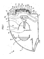
Fig. 1 is a drawing showing an exemplary embodiment of a vehicle headlamp of the invention together withFigs. 2 to 7 , which is a schematic vertical sectional view of the vehicle headlamp. -
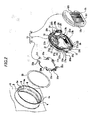
Fig. 2 is an exploded perspective view of a lamp body showing a cover mounting portion, an O ring and a back cover. -
Fig. 3 is an exploded perspective view showing a socket and the back cover. -
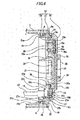
Fig. 4 is a front view showing a state in which a case member is mounted on a cover member. -
Fig. 5 is a rear view showing the state in which the case member is mounted on the cover member. -
Fig. 6 is an enlarged sectional view showing a state in which a back cover is mounted on a cover mounting portion of the lamp body. -
Fig. 7 is a block diagram showing an illumination circuit (a ballast) of a discharge lamp. - A back cover and a back cover assembling method according to an exemplary embodiment of the invention will be described by reference to the accompanying drawings.
- A vehicle lamp, that is, a
vehicle headlamp 1, for example, is disposed at each of both left- and right-hand end portions of a front end portion of a vehicle body. - As is shown in
Fig. 1 , thevehicle headlamp 1 includes a lamp body 2 having a recess portion which is made to open forwards and a front cover 3 which closes a front opening of the lamp body 2, and an interior space defined by the lamp body 2 and the front cover 3 is defined as a lamp chamber 4. - A
cover mounting portion 5, which is formed into a substantially cylindrical shape, is provided at a rear end portion of the lamp body 2 (refer toFig. 2 ). Thecover mounting portion 5 has a mounting opening 5a which penetrates therethrough in a front-rear direction.Engagement portions cover mounting portion 5. Theengagement portions cover mounting portion 5. - Spaces between the
engagement portions engagement portions - A
lamp unit 7 is disposed within the lamp chamber 4 (refer toFig. 1 ). The lamp unit has areflector 8, adischarge lamp 9 which is supported on thereflector 8, ashade 10 which is mounted on the reflector and alens 11 which is disposed in front of thedischarge lamp 9. - A
socket 12 is mounted at a rear end portion of thedischarge lamp 9, and astarter 12a is disposed in an interior of thesocket 12. Acable 13 is led out of thesocket 12, and aconnector 14 is coupled to an opposite end portion of thecable 13 to an end portion thereof which faces thesocket 12. Afixing piece 14a, which is caused to project sideways, is provided on theconnector 14, as is shown inFig. 3 , and ascrew inserting hole 14b is formed in the fixing piece so as to penetrate therethrough. - An
extension 15 is disposed in the lamp chamber 4 for closing part of thelamp unit 7. - A
back cover 16 is mounted on thecover mounting portion 5 of the lamp body 2 to close the mounting opening 5a (refer toFigs. 1 and2 ). As is shown inFigs. 2 and3 , theback cover 16 includes acover member 17 and acase member 18 which is mounted on thecover member 17 and which has a function as a heat dissipating member and a function to cover thecover member 17 from the rear. - The
cover member 17 is made up of a covermain body 19 which is formed from a resin material and aconnection terminal 20 which is formed of a metallic material, and the covermain body 19 and theconnection terminal 20 are molded integrally through insert molding (refer toFigs. 2 to 4 ). - The cover
main body 19 has afirst fitting portion 21 which has a substantially ring shape, aflange portion 22 which is caused to project radially outwards from a rear end portion of thefirst fitting portion 21, an innerstructural portion 23 which is provided inside theflange portion 22, asecond fitting portion 24 which is caused to project rearwards from a rear surface of an inner circumferential portion of theflange portion 22, and aconnector frame portion 25 which is caused to project rearwards from a rear surface of the innerstructural portion 23 and which is positioned on one side of thesecond fitting portion 24. -
Engagement projecting portions portion 21 so as to project radially outwards. A restricting projectingportion 21b is provided at least oneengagement projecting portion 21a out of theengagement projecting portions back cover 16, for example, fourengagement projecting portions portions engagement projecting portions - A
disposition hole 23a is formed in the innerstructural portion 23 so as to penetrate therethrough in a front-rear direction.Component disposing portions connector connecting portion 23c are formed on a front surface of the innerstructural portion 23. Largeelectronic components discharge lamp 9 are inserted to be disposed in thecomponent disposing positions - In the inner
structural portion 23,positioning holes structural portion 23 in the front-rear direction. - An inserting
hole 23e is formed at the upper end portion of the left end portion of the innerstructural portion 23 so as to penetrate therethrough in the front-rear direction. - As has been described above, since the
connection terminal 20 is molded integrally with the covermain body 19 through insert molding, theconnection terminal 20 is embedded in the covermain body 19 excluding part thereof. Consequently, the part of theconnection terminal 20 is allowed to project outwards from the cover main body 19 (refer toFigs. 4 to 6 ), and the projecting part of theconnection terminal 20 includescomponent terminal portions component disposition portions structural portion 23,connector terminal portions connector frame portion 25, connectingterminal portions structural portion 23 towards thedisposition hole 23a and electric power supplyingterminal portions connector connecting portion 23c. Thecomponent terminal portions leads electronic components component disposing portions structural portion 23 trough welding. - In this way, by connecting the
component terminal portions leads electronic components - As has been described above, by disposing the large
electronic components cover member 17, a reduction in size of theback cover 16 can be realized which is associated with the effective use of the space on thecover member 17. - A
screw inserting hole 20e is formed at an upper end portion of a right end portion of theconnection terminal 20 so as to penetrate therethrough in the front-rear direction. Thescrew inserting hole 20e is formed in a position which corresponds to the insertinghole 23e of the inner structural portion 23 (refer toFig. 4 ). - A
seal groove 27 is formed on the secondfitting portion 24 of thecover member 17 so as to extend in a circumferential direction while being made to open rearwards (refer toFigs. 2 and6 ). Theseal groove 27 is formed by aninner wall portion 27a which is positioned inside,outer wall portions inner wall portion 27a, and abottom wall portion 27c which connect front end portions of theinner wall portion 27a and theouter wall portions - Rising
wall portions connector frame portion 25 on a rear surface of theconnector member 17 so as to project rearwards. - The
case member 18 has the function as the heat dissipating member and is formed of a metallic material. Thecase member 18 is formed into a flat shape in the front-rear direction and has a shallowmounting recess portion 18a which is made to open forwards (refer toFigs. 2 ,3 and6 ). - An
elongate seal projection 18b is provided along a circumferential portion on a front surface of thecase member 18 so as to extend in a circumferential direction while being caused to project forwards. An innercircumferential wall 18c is provided inside theelongated seal projection 18b on thecase member 18, and the innercircumferential wall 18c extends in the circumferential direction while being caused to project forwards. Consequently, agroove portion 18d, which is made to open forwards, is defined between theelongated seal projection 18b and the innercircumferential wall 18c. - Screwing
holes case member 18 in the vicinity of the innercircumferential wall 18c so as to be spaced apart vertically (refer toFigs. 3 and4 ) . Positioning pins 18f, 18f are provided individually at an upper end portion of a left end portion and a lower end portion of a right end portion, and the positioning pins 18f, 18f are each caused to project forwards. - A
first shield wall 18g and asecond shield wall 18h are provided on thecase member 18. Thefirst shield wall 18g extends in a left-right direction to reach the innercircumferential wall 18c at a left end portion thereof and thesecond shield wall 18h extends in a vertical direction to reach a right end portion of thefirst shield wall 18g at an upper end portion thereof. -
Circuit boards recess portion 18a of thecase member 18 side by side in the left-right direction. A required number ofchip components circuit boards - Rear surfaces of the
circuit boards circuit boards recess portion 18a in such a state that the respective rear surfaces of thecircuit boards case member 18. - In this way, in the
back cover 16, since thechip components circuit boards circuit boards recess portion 18a in such a state that the rear surfaces, which are made into the flat planes, of thecircuit boards case member 18, there is provided a high heat transfer coefficient for heat generated in thecircuit boards back cover 16. - An electronic component (a DC-DC converter) 32, which makes up the illumination circuit, is mounted in the mounting recess portion of the
case member 18, and a terminal portion of theelectronic component 32 is connected to thecircuit board 30. Theelectronic component 32 is a component having a large heat value. - By the
electronic component 32 having the large heat value being disposed on thecase member 18 which functions as the heat dissipating member, an improvement in the heat dissipating performance of theback cover 16 can be realized. - The
electronic component 32 is disposed while being surround from four sides by thefirst shield wall 18g, thesecond shield wall 18h, part of the innercircumferential wall 18c and part of a wall portion which forms the mountingrecess portion 18a and which is oriented in the front-rear direction. Consequently, effects of noise that is generated when theelectronic component 32 is driven on thecircuit boards chip components - Heat dissipating
fins Figs. 5 and6 ). Theheat dissipating fins circuit boards electronic component 32, so as to improve the heat dissipating performances of thecircuit boards electronic component 32. - A
shield plate 33, which is formed from a metallic material, is mounted on a front side of the cover member 17 (refer toFigs. 2 ,3 and6 ).Engagement pieces shield plate 33 so as to be spaced apart in a circumferential direction while being caused to project rearwards. Screw insertingholes shield plate 33 so as to be spaced apart vertically while being caused to penetrate therethrough in the front-rear direction. - Radiation from the illumination circuit is stopped by the
shield plate 33 so as to realize a reduction in noise. - Hereinafter, an assembling method of the
back cover 16 will be described. - Firstly, the
case member 18 is mounted on thecover member 17. Mounting of thecase member 18 on thecover member 17 is implemented by filling an adhesive 34 in theseal groove 27 formed in the covermain body 19 and inserting theelongated seal projection 18b in theseal groove 27 to thereby join thecase member 18 to the covermain body 19. As this occurs, the positioning pins 18f, 18f of thecase member 18 are inserted individually into thecorresponding positioning holes cover member 17 for positioning of thecase member 18 relative to thecover member 17. - As is described above, by providing the positioning pins 18f, 18f on the
case member 18 and forming thepositioning holes cover member 17 for positioning thecase member 18 relative to thecover member 17, an improvement in positioning accuracy with which thecase member 18 is positioned relative to thecover member 17 can easily be realized. - As will be described later, when mounting or dismounting the
back cover 16 on or from thevehicle headlamp 1, although theback cover 16 is rotated relative to thecover mounting portion 5 of thevehicle headlamp 1, by inserting the positioning pins 18f, 18f into thepositioning holes case member 18 relative to thecover member 17 is prevented when theback cover 16 is rotated, thereby making it possible to prevent thecase member 18 from falling from thecover member 17. - The
elongated seal projection 18b is bonded to theseal groove 27 by the adhesive 34, whereby thecase member 18 is fixed to thecover member 17. In such a state that thecase member 18 is fixed to thecover member 17, no gap is produced between theseal groove 27 and theelongated seal projection 18b, whereby sealing property therebetween is ensured. - Although the example has been described above in which the adhesive 34 is filled in the
seal groove 27, in contrast to this, the adhesive 34 may be applied to theelongated seal projection 18b for thecase member 18 to be fixed to thecover member 17. In addition, the adhesive 34 may be not only filled in theseal groove 27 but also applied to theelongated seal projection 18b for theseal groove 27 and theelongated seal projection 18b to be bonded together, so that thecase member 18 is fixed to thecover member 17. - In such a state that the
case member 18 is fixed to thecover member 17, thecircuit boards electronic component 32 are positioned in thedisposition hole 23a formed in the cover member 17 (refer toFig. 6 ). Consequently, the space in the interior of theback cover 16 can be used effectively, thereby making it possible to make theback cover 16 thin. - Next, in such a state that the
case member 18 is fixed to thecovermember 17, the connectingterminal portions connection terminal 20 are connected individually to circuit patterns formed on thecircuit boards members terminal portions circuit boards electronic components component disposing portions circuit boards connection terminal 20. - Next, the
connector 14 is connected to the electric power supplyingterminal portions connection terminal 20. - Following this, the
shield plate 33 is mounted on front surface sides of thecover member 17 and thecase member 18. Mounting theshield plate 33 on thecover member 17 is implemented by theengagement pieces shield plate 33 being brought individually into engagement with an opening edge of the mountingrecess portion 18a of thecase member 18 via thedisposition hole 23a and further being screwed to thecase member 18. - The
shield plate 33 is screwed to thecase member 18, as is shown inFig. 3 , by inserting one metallic mountingscrew 100 sequentially through onescrew inserting hole 33b in theshield plate 33 and thescrew inserting hole 20e in theconnection terminal 20 to be screwed into one screwinghole 18e in thecase member 18 and inserting the other mountingscrew 100 sequentially through the otherscrew inserting hole 33b in theshield plate 33 and thescrew inserting hole 14b in theconnector 14 to be screwed into the other screwinghole 18e in thecase member 18. - The
back cover 16 is made up by screwing theshield plate 33 to thecase member 18 in the way described above. - By joining the
metallic shield plate 33, part of themetallic connection terminal 20 and themetallic case member 18 together by the metallic mountingscrews back cover 16 can be reduced. - Since, by part of the
connection terminal 20 and thecase member 18 being joined together by the mountingscrews case member 18 is fixed to thecover member 17 through screwing in addition to bonding by the adhesive 34, an improvement in fixing strength with which thecase member 18 is fixed to thecover member 17 can be realized. - Following this, an
O ring 36 is fitted on an outer circumferential surface of the firstfitting portion 21 of the cover main body 19 (refer toFigs. 2 and6 ). As this occurs, although there is a fear that theO ring 36 comes into contact with theengagement projecting portions engagement projecting portions O ring 36 comes into contact with theengagement projecting portions O ring 36 can be prevented from being damaged by the contact. - With the
O ring 36 fitted on the firstfitting portion 21 and theengagement projecting portions engagement portions cover member 17 is rotated in the circumferential direction. When thecover member 17 is rotated, as is shown inFig. 6 , rear surfaces of theengagement projecting portions engagement portions back cover 16 is mounted on thecover mounting portion 5 of the lamp body 2, and theO ring 36 is closely attached to theengagement portions flange portion 22 of theback cover 16. - When the
back cover 16 is attempted to be mounted on thecover mounting portion 5, for example, in the event that theback cover 16 is inclined relative to thecover mounting portion 5, depending upon an inclination angle of theback cover 16, the restricting projectingportions 21b which are provided on theengagement projecting portions 21a come into contact with rear surfaces of theengagement portions 6 or opening edges of the inserting cutouts 6a. Consequently, in the event that theback cover 16 is not properly oriented relative to thecover mounting portion 5 in the way described above, the insertion of theengagement projecting portions portions 21b, whereby theback cover 16 cannot be mounted on thecover mounting portion 5. - In contrast, when the
back cover 16 is attempted to be mounted on thecover mounting portion 5, even though theback cover 16 is inclined relative to thecover mounting portion 5, there is a possibility that theengagement projecting portions back cover 16 attempts to rotate in the circumferential direction relative to thecover mounting portion 5, since theback cover 16 is inclined, the restricting projectingportions 21 come into contact with the opening edges of the inserting cutouts 6a, whereby theback cover 16 is prevented from rotating. Consequently, in this case, too, theback cover 16 is not allowed to be mounted on thecover mounting portion 5. - In the
back cover 16 as described above, by providing the restricting projectingportions 21b on theengagement projecting portions 21a, theback cover 16 can be prevented from being mounted on thecover mounting portion 5 in an incomplete condition when theback cover 16 is oriented improperly relative to the cover mounting portion. Namely, theback cover 16 can be prevented from being mounted on thecover mounting portion 5 in the incomplete condition in which only part of theengagement projecting portions 21a are inserted in the inserting cutouts 6a, while the otherengagement projecting portions 21a are not inserted in the inserting cutouts 6a. - Although in this embodiment, the restricting projecting
portion 21b is described as being provided on at least one of theengagement projecting portions 21a, in theback cover 16, a configuration can be adopted in which no restricting projectingportion 21b is provided on any of theengagement projecting portions - In the
vehicle headlamp 1 configured as has been described heretofore, since theback cover 16 is configured as the single integral unit in which thecase member 18 is mounted on thecover member 17 on which theelectronic components electronic component 32 and thechip components vehicle headlamp 1 be realized, but also the detachment and attachment of theback cover 16 can easily be performed whendischarge lamps 9 are replaced. - Since the sealing property between the
back cover 16 and thecover mounting portion 5 of the lamp body 2 is ensured by theO ring 36, infiltration of water (vapor) contained in the atmosphere or outside water into the lamp chamber 4 can be prevented. - Hereinafter, an example of an illumination circuit (a ballast) for the
discharge lamp 9 will be described (refer toFig. 7 ). - An
input filter 38a which is connected to a directcurrent power supply 37 via a switch S1 suppresses noise generated from aballast 38 and noise attempting to infiltrate into theballast 38. - A DC-
DC converter 38b (the electronic component 32), which is a direct current-direct current converter circuit connected to theinput filter 38a, receives a direct current input voltage from the directcurrent power supply 37 via theinput filter 38a to raise the input voltage to a desired direct current voltage. - In the DC-
DC converter 38b, a switching element in an interior thereof is driven by a control signal from acontrol circuit 38e. - A
full bridge inverter 38c, which is a direct current-alternating current conversion circuit, first converts an output voltage of the DC-DC converter 38b into an alternating current voltage (a square wave) and then supplies the alternating current voltage to thedischarge lamp 9. In thefull bridge inverter 38c, for example, two arms are configured by four switching elements and includes driving circuits for driving individually the switching elements of each arm. Thefull bridge inverter 38c outputs an alternating current by on/off controlling the two pairs of switching elements in a conflicting fashion. The switching elements in an interior of thefull bridge inverter 38c are driven by a control signal from acontrol circuit 38e. - A
voltage increasing circuit 38d imparts an increased voltage to astarter 12a. When activated, thestarter 12a generates a high voltage pulse (for example, about 25kV). - The
control circuit 38e controls the illumination of the discharge lamp 9 (a transient/constant power control). Conceptually, thecontrol circuit 38e also includes a fail-safe circuit for detecting abnormal inputs and outputs and controlling ceasing of the operation. - As has been described heretofore, in the
vehicle headlamp 1, theseal groove 27, which is made to open rearwards, is formed on thecover member 17, and theelongated seal projection 18b is provided on thecase member 18 so that theelongated seal projection 18b is bonded to be mounted in theseal groove 27 while being fitted in theseal groove 27. - Consequently, good sealing property is secured between the
cover member 17 and thecase member 18, and hence infiltration of water (vapor) contained in the atmosphere or outside water into the illumination circuit or the lamp chamber 4 can be prevented, whereby not only can an operation failure of the illumination circuit for the light source be prevented, but also fogging of the front cover 3 can be prevented. - Since good sealing property is secured between the
cover member 17 and thecase member 18 to thereby improve the mounting strength between both the members, the generation of looseness of thecase member 18 relative to thecover member 17 or the generation of a drawback that thecase member 18 falls from thecover member 17 can be prevented. - Since the
cover member 17 is formed by integrally molding theconnection terminal 20 and the covermain body 19, the number of components of thevehicle headlamp 1 can be reduced. - In the
back cover 16, since the risingwall portions connector frame portion 25 of thecover member 17, the hands of an assembler or other surrounding objects are never brought into contact with theconnector frame portion 25 and theconnector terminal portions connector frame portion 5 when theback cover 16 is mounted on thecover mounting portion 5 of the lamp body 4 or thevehicle lamp 1 is mounted on a vehicle body, thereby making it possible to prevent any damage to theconnector frame portion 25 and theconnector terminal portions - In addition, when the
back cover 16 is rotated to be mounded on or dismounted from thecover mounting portion 5, the risingwall portions back cover 16 on or from thecover mounting portion 5. - In the embodiment described above, although the
seal groove 27 is described as being formed on thecover member 17 and theelongated seal projection 18b is described as being provided on thecase member 18, on the contrary, a configuration may be adopted in which an elongated seal projection is provided on the cover member, while a seal groove is formed on the case member, so that thecase member 18 is fixed to thecover member 17. - In the
vehicle headlamp 1, although the covermain body 19 is formed from the resin material, it is possible to suppress noise associated with the illumination circuit by forming a covermain body 19 using a conductive material and a non-conductive material through a so-called two-color molding so that part of the covermain body 19 is made up of the conductive material, thereby making it possible to suppress noise associated with the illumination circuit. - In the above embodiment, the
starter 12a is described as being disposed on thedischarge lamp 9 side (in the interior of the socket 12) within the lamp chamber 4 . However, the disposing position of thestarter 12 is not limited to that position, and hence, for example, the starter may be disposed on the illumination circuit side (in the interior of the back cover 16). - In the embodiment described above, the
vehicle headlamp 1 utilizing thedischarge lamp 9 is described as the example of the vehicle lamp. However, as the vehicle lamp, for example, in addition to thevehicle headlamp 1, a daytime running lamp, a tail and stop combination lamp, a turn indicator or the like can be used. - The light source is not necessarily limited to the
discharge lamp 9. For example, a filament type bulb or a semiconductor light emitting device such as an LED (Light Emitting Diode) can be used as a light source. - The illumination circuit disposed in the
back cover 16 may be such as to have functions to turn on and off the light source and to change (or adjust) the brightness of the light source in addition to the function to illuminate the light source at a predetermined brightness. - While description has been made in connection with a specific exemplary embodiment of the invention, it will be obvious to those skilled in the art that various changes and modification may be made therein without departing from the present invention. It is aimed, therefore, to cover in the appended claims all such changes and modifications falling within the true spirit and scope of the present invention.
- 1 vehicle headlamp; 2 lamp body; 3 front cover; 4 lamp chamber; 5 cover mounting portion; 5a mounting opening; 6 engagement portion; 6a inserting cutout; 9 discharge lamp (light source); 16 back cover; 14 connector; 18 case member; 18a mounting recess portion; 18b elongated seal projection; 18e screwing hole; 18f positioning pin; 19 cover main body; 20 connection terminal; 20b connector terminal portion; 20d electric power supplying terminal portion; 20e screw inserting hole; 21 first fitting portion; 21b restricting projecting portion; 24 second fitting portion; 25 connector frame portion; 26 electronic component; 26a lead; 27 seal groove; 28 rising wall portion; 29 circuit board; 30 circuit board; 31 chip component; 32 electronic component; 33 shield plate; 35 connecting member; 100 mounting screw.
Claims (8)
- A back cover (16) to be attached to a cover mounting portion (5) of a vehicle lamp (1) in which a light source (9) is disposed in a lamp chamber (4) defined by a lamp body (2) on which said cover mounting portion (5) having a mounting opening (5a) is provided at a rear end portion of the lamp body (2) and a front cover (3) which covers a front of the lamp body (2), characterized in that the back cover (16) comprises:a cover main body (19) formed from a resin material and including a first fitting portion (21) provided on a front end side of the cover main body (19) and adapted to fit in the cover mounting portion (5) and a second fitting portion (24) provided on a rear end side of the cover main body (19);a connection terminal (20) formed of a metallic material and partially embedded in the cover main body (19) so as to be integrally formed with the cover main body (19);a metallic case member (18) fitted in the second fitting portion (24) and including a mounting recess portion (18a) made to open forwards;a circuit board (29, 30) disposed within the mounting recess portion (18a) and connected with the connection terminal (20);an electronic component (32) disposed within the mounting recess portion (18a) and connected with the circuit board (29, 30);a power supply terminal portion (20d) provided on a part of the connection terminal (20) and adopted to be connected with a light source side connector (14) for supplying electric power to the light source (9);a connector terminal portion (20b) provided on another part of the connection terminal (20) and adapted to be connected with a power supply side connector for receiving electric power from a power supply side;a connector frame portion (25) provided on the cover main body (19) and adopted to cover the connector terminal portion (20b) from a circumference of the connector terminal portion (20b);a seal groove (27) formed on one of the second fitting portion (24) and the case member (18) to open forwards or rearwards and extending in a circumferential direction; andan elongated seal projection (18b) formed on the other of the second fitting portion (24) and the case member (18) to project rearwards or forwards and extending in the circumferential direction, wherein the elongated seal projection (18b) is fixed to the seal groove (27) in a condition where the elongated seal projection (18b) is fitted in the seal groove (27) and bonded to the seal groove (27).
- The back cover according to Claim 1, further comprising:a rising wall portion (28) provided on an outer circumferential side of the connector frame portion (25) and covering at least a part of a circumference of the connector frame portion (25).
- The back cover according to Claim 1 or 2, further comprising:an insertion hole (23e) formed in the cover main body (19) and penetrating through the cover main body (19) in a front-rear direction;a screw inserting hole (20e) formed in the connection terminal (20) and positioned in association with the insertion hole (23e);a screwing hole (18e) formed in the case member (18) and positioned in association with the insertion hole (23e); anda metallic shield plate (33) adapted to cover the connection terminal (20) from a front thereof, wherein the shield plate (33) is fixed to the case member (18) by a screw (100) which is inserted through the screw inserting hole (20e) and the insertion hole (23e) to be screwed into the screwing hole (18e).
- The back cover according to any one of Claims 1 to 3, further comprising:a component disposing portion (23b) provided in the cover member (19); andan electronic component (26) having a lead (26a) and disposed in the component disposing portion (23b), wherein the lead (26a) of the electronic component (26) is connected to the connection terminal (20) by welding.
- The back cover according to any one of Claims 1 to 4, further comprising:a positioning hole (23d) formed in the cover main body (19); anda positioning pin (18f) provided on the case member (18) and inserted in the positioning hole (23d).
- The back cover according to any one of Claims 1 to 5, further comprising a chip component (31) mounted on one surface of the circuit board (29, 30),
wherein the other surface of the circuit board (29, 30) is formed into a flat plane, and
the circuit board (29, 30) is mounted on the case member (18), and the other surface of the circuit board (29, 30) is in surface contact with the case member (18). - The back cover according to any one of Claims 1 to 6, further comprising:a plurality of engagement projecting portions (21a) provided at a front end portion of the first fitting portion (21) so as to be positioned spaced apart from each other in a circumferential direction, wherein the cover mounting portion (5) of the lamp body (2) includes a plurality of inserting cutouts (6a) into which the plurality of engagement projecting portions (21a) are inserted individually from a rear thereof and a plurality of engagement portions (6) with which the plurality of engagement projecting portions (21a) are brought into engagement when the cover main body (19) is rotated in the circumferential direction in such a state that the plurality of engagement projecting portions (21a) are inserted individually into the plurality of inserting cutouts (6a) from the rear thereof; anda restricting projecting portion (21b) projecting forwards and provided at least one of the plurality of engagement projecting portions (21a).
- A method of assembling a back cover to be attached to a cover mounting portion (5) of a vehicle lamp in which a light source (9) is disposed in a lamp chamber (4) defined by a lamp body (2) on which said cover mounting portion (5) having a mounting opening (5a) is provided at a rear end portion of the lamp body (2) and a front cover (3) which covers a front of the lamp body (2), characterized in that the method comprises:providing a seal groove (27) on one of a cover main body (19) and a metallic case member (18) to open forwards or rearwards,wherein said cover main body (19) is integrally molded with a connection terminal (20) made of a metallic material in such a state that the connection terminal (20) is mostly embedded in the cover main body (19), and wherein a circuit board (29, 30) is mounted on said case member (18);
providing an elongated seal projection (18b) on the other of said cover main body (19) and said case member (18) to project rearwards or forwards;
butting and fitting the seal groove (27) and the elongated seal projection (18b) in a front-rear direction;
bonding the seal groove (27) and the elongated seal projection (18b) so that the case member (18) is fixed to the cover main body (19); and
connecting the connection terminal (20) with the circuit board (29, 30) by a metallic connection member (35).
Applications Claiming Priority (2)
| Application Number | Priority Date | Filing Date | Title |
|---|---|---|---|
| JP2009038519 | 2009-02-20 | ||
| JP2009139438A JP2010219019A (en) | 2009-02-20 | 2009-06-10 | Back cover and method of assembling back cover |
Publications (1)
| Publication Number | Publication Date |
|---|---|
| EP2221216A1 true EP2221216A1 (en) | 2010-08-25 |
Family
ID=42199491
Family Applications (1)
| Application Number | Title | Priority Date | Filing Date |
|---|---|---|---|
| EP10153956A Withdrawn EP2221216A1 (en) | 2009-02-20 | 2010-02-18 | Back cover and method of assembling back cover |
Country Status (4)
| Country | Link |
|---|---|
| US (1) | US8408770B2 (en) |
| EP (1) | EP2221216A1 (en) |
| JP (1) | JP2010219019A (en) |
| CN (1) | CN101813307B (en) |
Cited By (1)
| Publication number | Priority date | Publication date | Assignee | Title |
|---|---|---|---|---|
| EP3385604A1 (en) * | 2017-04-06 | 2018-10-10 | Valeo Iluminacion | Lighting device |
Families Citing this family (10)
| Publication number | Priority date | Publication date | Assignee | Title |
|---|---|---|---|---|
| AT507555B1 (en) * | 2009-04-02 | 2010-06-15 | Zizala Lichtsysteme Gmbh | VEHICLE HEADLIGHTS WITH A DEVICE FOR CONNECTING TWO COMPONENTS OF THIS VEHICLE HEADLAMP |
| EP2458273B1 (en) * | 2010-11-30 | 2014-10-15 | LG Innotek Co., Ltd. | Lighting device |
| CN102291904A (en) * | 2011-08-16 | 2011-12-21 | 广东雪莱特光电科技股份有限公司 | Cover-shaped soft waterproof vehicle light power converter |
| US9151459B2 (en) | 2011-10-11 | 2015-10-06 | Sabic Global Technologies B.V. | Mounting structure for a headlamp reflector |
| JP6045246B2 (en) * | 2012-08-07 | 2016-12-14 | 株式会社小糸製作所 | Light source lighting device |
| JP2014132546A (en) * | 2012-12-04 | 2014-07-17 | Koito Mfg Co Ltd | Lighting device for vehicle |
| JP2014157710A (en) * | 2013-02-15 | 2014-08-28 | Koito Mfg Co Ltd | Vehicle lighting device |
| FR3039474B1 (en) * | 2015-07-31 | 2021-02-19 | Valeo Iluminacion Sa | DEVICE FOR CLOSING A VEHICLE OPTICAL BOX OPENING, OPTICAL BOX EQUIPPED WITH SUCH A DEVICE AND CORD FOR SUCH DEVICE |
| JP6765241B2 (en) * | 2016-07-13 | 2020-10-07 | 株式会社小糸製作所 | Lighting device for vehicles |
| CN211371957U (en) * | 2019-09-11 | 2020-08-28 | 欧普照明股份有限公司 | Lamp set |
Citations (5)
| Publication number | Priority date | Publication date | Assignee | Title |
|---|---|---|---|---|
| DE19600638A1 (en) * | 1995-01-24 | 1996-07-25 | Valeo Vision | Motor vehicle headlamp with removable housing for control electronics |
| EP0854315A2 (en) * | 1997-01-16 | 1998-07-22 | Honda Giken Kogyo Kabushiki Kaisha | Headlamp for vehicle |
| US20020067617A1 (en) * | 2000-12-06 | 2002-06-06 | Koito Manufacturing Co., Ltd. | Vehicle headlamp |
| JP2002367413A (en) * | 2001-06-07 | 2002-12-20 | Matsushita Electric Works Ltd | In-vehicle discharge lamp lighting device |
| US20080266892A1 (en) * | 2007-04-26 | 2008-10-30 | Koito Manufacturing Co., Ltd. | Vehicle headlight |
Family Cites Families (7)
| Publication number | Priority date | Publication date | Assignee | Title |
|---|---|---|---|---|
| JPS6299105U (en) * | 1985-12-13 | 1987-06-24 | ||
| JPH07114819A (en) * | 1993-10-15 | 1995-05-02 | Matsushita Electric Works Ltd | Illuminating lamp device |
| JP3965712B2 (en) * | 1996-11-12 | 2007-08-29 | 市光工業株式会社 | Vehicle lighting |
| JP4471169B2 (en) * | 2005-04-21 | 2010-06-02 | 株式会社小糸製作所 | Projector type vehicle lamp unit |
| JP4671852B2 (en) * | 2005-12-08 | 2011-04-20 | 株式会社小糸製作所 | Vehicle lighting |
| JP4500273B2 (en) * | 2006-01-31 | 2010-07-14 | 株式会社小糸製作所 | Vehicle headlamp |
| CN201196403Y (en) * | 2008-05-16 | 2009-02-18 | 重庆长星光电子制造有限公司 | A universal light source body for LED lighting with heat dissipation design |
-
2009
- 2009-06-10 JP JP2009139438A patent/JP2010219019A/en active Pending
-
2010
- 2010-02-12 US US12/704,632 patent/US8408770B2/en not_active Expired - Fee Related
- 2010-02-18 EP EP10153956A patent/EP2221216A1/en not_active Withdrawn
- 2010-02-20 CN CN2010101147005A patent/CN101813307B/en not_active Expired - Fee Related
Patent Citations (5)
| Publication number | Priority date | Publication date | Assignee | Title |
|---|---|---|---|---|
| DE19600638A1 (en) * | 1995-01-24 | 1996-07-25 | Valeo Vision | Motor vehicle headlamp with removable housing for control electronics |
| EP0854315A2 (en) * | 1997-01-16 | 1998-07-22 | Honda Giken Kogyo Kabushiki Kaisha | Headlamp for vehicle |
| US20020067617A1 (en) * | 2000-12-06 | 2002-06-06 | Koito Manufacturing Co., Ltd. | Vehicle headlamp |
| JP2002367413A (en) * | 2001-06-07 | 2002-12-20 | Matsushita Electric Works Ltd | In-vehicle discharge lamp lighting device |
| US20080266892A1 (en) * | 2007-04-26 | 2008-10-30 | Koito Manufacturing Co., Ltd. | Vehicle headlight |
Cited By (1)
| Publication number | Priority date | Publication date | Assignee | Title |
|---|---|---|---|---|
| EP3385604A1 (en) * | 2017-04-06 | 2018-10-10 | Valeo Iluminacion | Lighting device |
Also Published As
| Publication number | Publication date |
|---|---|
| JP2010219019A (en) | 2010-09-30 |
| US8408770B2 (en) | 2013-04-02 |
| CN101813307B (en) | 2012-12-05 |
| US20100214800A1 (en) | 2010-08-26 |
| CN101813307A (en) | 2010-08-25 |
Similar Documents
| Publication | Publication Date | Title |
|---|---|---|
| US8408770B2 (en) | Back cover and method of assembling back cover | |
| US7909495B2 (en) | Vehicle headlight having component inlaying portions and radiator body | |
| US8870426B2 (en) | Illumination unit for vehicle headlights and vehicle headlights | |
| CN102084180B (en) | Lighting unit for automotive headlamps and automotive headlamps | |
| EP3279552A1 (en) | Light source unit and vehicle lamp fitting | |
| CN106338043B (en) | Light source unit, lighting device, and vehicle | |
| US6550935B1 (en) | Illumination device having an inverter and an igniter disposed in a lamp body | |
| CN108800032B (en) | Lamp assembly for a headlamp | |
| JP3279476B2 (en) | Lighting device for discharge lamp | |
| US8393771B2 (en) | Vehicle headlamp | |
| JP4361766B2 (en) | Automotive lighting or display devices with complementary modules | |
| JP4554225B2 (en) | Automotive headlight device with an insertable additional module | |
| CN104613399A (en) | Vehicle headlamp with LED light source | |
| JP2012119243A (en) | Led standard module, and vehicular lamp having the same | |
| JP6232732B2 (en) | LED driving device and mounting structure thereof | |
| JP4635623B2 (en) | Discharge lamp lighting device and lighting apparatus including the same | |
| CN100526710C (en) | Electronic ballast and illuminating device | |
| CN115707201B (en) | LED driver module and vehicle including the same | |
| CN103574543B (en) | The ignition device of light source | |
| JP5170769B2 (en) | Discharge lamp lighting device | |
| JP6214283B2 (en) | Gas discharge lamps, especially for automobile headlamps | |
| JP2014032812A (en) | Lighting device | |
| JP2011216393A (en) | Lighting control device and headlamp device | |
| EP3933251A1 (en) | Led lamp for vehicle headlamp | |
| JP2012116267A (en) | LED license lamp |
Legal Events
| Date | Code | Title | Description |
|---|---|---|---|
| PUAI | Public reference made under article 153(3) epc to a published international application that has entered the european phase |
Free format text: ORIGINAL CODE: 0009012 |
|
| 17P | Request for examination filed |
Effective date: 20100218 |
|
| AK | Designated contracting states |
Kind code of ref document: A1 Designated state(s): AT BE BG CH CY CZ DE DK EE ES FI FR GB GR HR HU IE IS IT LI LT LU LV MC MK MT NL NO PL PT RO SE SI SK SM TR |
|
| AX | Request for extension of the european patent |
Extension state: AL BA RS |
|
| STAA | Information on the status of an ep patent application or granted ep patent |
Free format text: STATUS: THE APPLICATION IS DEEMED TO BE WITHDRAWN |
|
| 18D | Application deemed to be withdrawn |
Effective date: 20160901 |