EP2220954A1 - Internal ventilation system applicable to footwear with sole made through direct injection or pouring onto the upper - Google Patents
Internal ventilation system applicable to footwear with sole made through direct injection or pouring onto the upper Download PDFInfo
- Publication number
- EP2220954A1 EP2220954A1 EP10425012A EP10425012A EP2220954A1 EP 2220954 A1 EP2220954 A1 EP 2220954A1 EP 10425012 A EP10425012 A EP 10425012A EP 10425012 A EP10425012 A EP 10425012A EP 2220954 A1 EP2220954 A1 EP 2220954A1
- Authority
- EP
- European Patent Office
- Prior art keywords
- sole
- ventilation
- ventilation system
- ventilation chamber
- insole
- Prior art date
- Legal status (The legal status is an assumption and is not a legal conclusion. Google has not performed a legal analysis and makes no representation as to the accuracy of the status listed.)
- Granted
Links
- 238000009423 ventilation Methods 0.000 title claims abstract description 68
- 238000002347 injection Methods 0.000 title claims abstract description 15
- 239000007924 injection Substances 0.000 title claims abstract description 15
- 239000000463 material Substances 0.000 claims abstract description 22
- 238000000465 moulding Methods 0.000 claims abstract description 7
- 229920003023 plastic Polymers 0.000 claims abstract description 6
- 239000004033 plastic Substances 0.000 claims abstract description 6
- 239000011358 absorbing material Substances 0.000 claims abstract description 5
- 238000000034 method Methods 0.000 claims description 12
- 229920002635 polyurethane Polymers 0.000 claims description 12
- 239000004814 polyurethane Substances 0.000 claims description 12
- 239000007788 liquid Substances 0.000 claims description 6
- 230000007246 mechanism Effects 0.000 claims description 3
- XLYOFNOQVPJJNP-UHFFFAOYSA-N water Substances O XLYOFNOQVPJJNP-UHFFFAOYSA-N 0.000 claims description 3
- 230000015572 biosynthetic process Effects 0.000 claims description 2
- 238000004891 communication Methods 0.000 claims description 2
- 238000013461 design Methods 0.000 claims description 2
- 238000005187 foaming Methods 0.000 claims description 2
- 230000002265 prevention Effects 0.000 claims description 2
- 238000007493 shaping process Methods 0.000 claims description 2
- 238000004519 manufacturing process Methods 0.000 description 6
- 239000012528 membrane Substances 0.000 description 5
- 210000004243 sweat Anatomy 0.000 description 5
- 238000007906 compression Methods 0.000 description 2
- 238000003780 insertion Methods 0.000 description 2
- 230000037431 insertion Effects 0.000 description 2
- 238000007711 solidification Methods 0.000 description 2
- 230000008023 solidification Effects 0.000 description 2
- 229920002994 synthetic fiber Polymers 0.000 description 2
- 230000002745 absorbent Effects 0.000 description 1
- 239000002250 absorbent Substances 0.000 description 1
- 238000009825 accumulation Methods 0.000 description 1
- 238000004026 adhesive bonding Methods 0.000 description 1
- 238000006243 chemical reaction Methods 0.000 description 1
- 230000006835 compression Effects 0.000 description 1
- 230000006837 decompression Effects 0.000 description 1
- 230000000694 effects Effects 0.000 description 1
- 230000008030 elimination Effects 0.000 description 1
- 238000003379 elimination reaction Methods 0.000 description 1
- 238000002955 isolation Methods 0.000 description 1
- 238000012986 modification Methods 0.000 description 1
- 230000004048 modification Effects 0.000 description 1
- 239000005871 repellent Substances 0.000 description 1
- 239000004576 sand Substances 0.000 description 1
- 230000035945 sensitivity Effects 0.000 description 1
Images


Classifications
-
- A—HUMAN NECESSITIES
- A43—FOOTWEAR
- A43B—CHARACTERISTIC FEATURES OF FOOTWEAR; PARTS OF FOOTWEAR
- A43B7/00—Footwear with health or hygienic arrangements
- A43B7/06—Footwear with health or hygienic arrangements ventilated
- A43B7/08—Footwear with health or hygienic arrangements ventilated with air-holes, with or without closures
- A43B7/082—Footwear with health or hygienic arrangements ventilated with air-holes, with or without closures the air being expelled to the outside
-
- A—HUMAN NECESSITIES
- A43—FOOTWEAR
- A43B—CHARACTERISTIC FEATURES OF FOOTWEAR; PARTS OF FOOTWEAR
- A43B13/00—Soles; Sole-and-heel integral units
- A43B13/02—Soles; Sole-and-heel integral units characterised by the material
- A43B13/12—Soles with several layers of different materials
-
- B—PERFORMING OPERATIONS; TRANSPORTING
- B29—WORKING OF PLASTICS; WORKING OF SUBSTANCES IN A PLASTIC STATE IN GENERAL
- B29D—PRODUCING PARTICULAR ARTICLES FROM PLASTICS OR FROM SUBSTANCES IN A PLASTIC STATE
- B29D35/00—Producing footwear
- B29D35/06—Producing footwear having soles or heels formed and joined on to preformed uppers using a moulding technique, e.g. by injection moulding, pressing and vulcanising
-
- B—PERFORMING OPERATIONS; TRANSPORTING
- B29—WORKING OF PLASTICS; WORKING OF SUBSTANCES IN A PLASTIC STATE IN GENERAL
- B29D—PRODUCING PARTICULAR ARTICLES FROM PLASTICS OR FROM SUBSTANCES IN A PLASTIC STATE
- B29D35/00—Producing footwear
- B29D35/12—Producing parts thereof, e.g. soles, heels, uppers, by a moulding technique
- B29D35/14—Multilayered parts
- B29D35/142—Soles
Definitions
- This invention relates to an internal ventilation system that can be applied to footwear with sole made through the injection or pouring of plastic material directly onto the upper.
- footwear serves to protect the foot while walking.
- Such function requires the foot to remain for too long inside the closed areas of the footwear, which withholds body heat and does not allow the foot to breathe, however.
- This often causes - especially in wearers with sensitivity in regard - the foot to sweat and emit odor caused by the accumulation of perspiration inside.
- Such wearers often have trouble finding shoes that reduce this problem, which increases during warmer weather or whenever sports activities are performed.
- the aim of this invention is the application of an internal footwear ventilation system with a sole applied directly onto the upper through either the direct injection or pouring process .
- the footwear article be composed of:
- Figure 1 provides a perspective view of a footwear article that shows the application of the ventilation valve at the side.
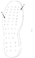
- Fig. 2 provides a perspective view of the insole.
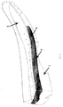
- Fig. 3 offers a perspective view of the ventilation chamber.
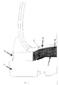
- Fig. 4 provides a perspective view of the entire ventilation system inside the footwear article.
- Fig. 5 offers a perspective view of the footwear article that shows the application of the ventilation valve at the base of the sole. The best way to produce the invention using an injection or pouring production process will be illustrated below.
- the footwear article ( Fig. 1 ) is composed of a sole 1, an upper 2, an insole 3, a ventilation chamber 4, a non-return expulsion valve 5 and a slender layer of non-absorbent material 7, bonded to the lower surface of the ventilation chamber and incorporated in the sole 1.
- the insole 3 ( Fig. 2 ) has ventilation holes 6 near the ventilation chamber 4.
- the ventilation chamber 4 ( Fig. 3 ) is composed of a spongy, open-cell material positioned beneath the insole 3 and therefore is positioned between the shoe's sole 1 and insole 3.
- the characteristics of the material used for the ventilation chamber are fundamental for the shoe's correct breathability.
- the spongy, elastic, open-cell material (in other words, with cells in communication with one another) was expressly selected for its physical characteristics of remarkable breathability that permits constant air exchange, prevention of the formation of humidity, and high mechanical resistance. For this reason, during walking, the mechanical compression of the foot against the ground forces the air in the shoe downwards, and this air flows through the ventilation holes 6 in the insole 3 before reaching the ventilation chamber 4 which is also involved in the compression process and expels the air outward through the non-return valve 5 ( Fig. 4 ) positioned at the side in a preferred embodiment or positioned at the base of the sole in a second embodiment 5a) ( Fig. 5 ).
- the non-return expulsion valve 5 ( Fig. 4 ) can be positioned at the side in the shoe's sole 1 in a preferred embodiment or positioned at the base of the sole in a second embodiment 5a) ( Fig. 5 ) in central and/or front and/or rear position.
- the non-return expulsion valve 5/5a) is connected inside the sole with the ventilation chamber 4.
- Said valve is equipped with a non-return mechanism that permits the air to flow out of the shoe while preventing air and water from entering through an inverse process ( Fig. 4 ).
- the valve can be cylindrical or conical.
- the ventilation chamber 4 may be preferably obtained through the shaping of sheets of spongy, open-cell material of less thickness than the sole's total thickness and with an outline a few millimeters smaller than the outline of the insole.
- the ventilation chamber 4 is glued onto the upper surface with the insole 3 already provided with its ventilation holes 6 in its surface.
- the ventilation chamber 4 is covered on its lower surface with a thin layer of non-absorbing material 7 that prevents the polyurethane injected or poured during the moulding of the sole from being absorbed by the open cells in the spongy material which would otherwise compromise correct function.
- the non-return valve 5, 5a) can be prepared and provided in the mould for the sole or inserted subsequently in the sole previously moulded with adequate housing for the valve in mind.
- liquid synthetic material e.g. polyurethane
- adequate solidification time must be allowed to pass before the footwear article created is removed from the mould.
- liquid synthetic material is poured from above into a closed mould for the direct moulding of the sole onto the upper and then adequate solidification time must be allowed to pass before the footwear article created is removed from the mould.
- the sole is moulded directly onto the upper by exploiting the high intrinsic adhesion power of polyurethane, which after chemical reaction coagulates and adheres to the upper in order to provide a sole moulded directly onto this latter. The insertion of ventilation systems when these two processes were used was not possible until now.
- the upper is inserted onto the last, the top part of the last is closed, and then the gate is opened for the injection or pouring of the liquid polyurethane inside the mould.
- the liquid polyurethane fills up all the empty parts of the mould in conformation with the design of the sole prepared with the mould in which the ventilation chamber has already been prepared as described above.
- the polyurethane will exactly cover the upper's external shape, including the external shape of the ventilation chamber. In this way, as described, a footwear article with a sole incorporating an efficient ventilation system moulded directly onto the upper is obtained.
- the ventilation chamber and the non-return expulsion valve are inserted in a footwear article in which the sole is directly moulded onto the upper, they are bonded together through a polyurethane injection and/or pouring process, and this provides the footwear article with better isolation against the cold and gives the ventilation chamber and non-return expulsion valve an airtight seal that also increases decompression and the flow of air from inside to outside the footwear article while also precluding the entry of air or water from outside the shoe inside.
- the non-return expulsion valve is positioned on the tread and at the side of the sole, its perfect and continuous operation is guaranteed because it neither clogs or breaks as it is not in contact with the ground.
Landscapes
- Engineering & Computer Science (AREA)
- Mechanical Engineering (AREA)
- Health & Medical Sciences (AREA)
- Epidemiology (AREA)
- General Health & Medical Sciences (AREA)
- Public Health (AREA)
- Chemical & Material Sciences (AREA)
- Materials Engineering (AREA)
- Footwear And Its Accessory, Manufacturing Method And Apparatuses (AREA)
Abstract
Description
- This invention relates to an internal ventilation system that can be applied to footwear with sole made through the injection or pouring of plastic material directly onto the upper. As is commonly known, footwear serves to protect the foot while walking. Such function requires the foot to remain for too long inside the closed areas of the footwear, which withholds body heat and does not allow the foot to breathe, however. This often causes - especially in wearers with sensitivity in regard - the foot to sweat and emit odor caused by the accumulation of perspiration inside. Such wearers often have trouble finding shoes that reduce this problem, which increases during warmer weather or whenever sports activities are performed. Various types of footwear have been developed to solve this problem by permitting the elimination of the sweat produced by the foot through the use of breathable soles with holes and the insertion of a breathable, water-repellent membrane or mechanisms in which a system of cushions communicating with the outside of the shoe through body moisture expulsion valves is positioned between the sole's perforated insole and sole in which such body moisture expulsion valves can be applied in different ways according to their method of production, and precisely beneath the shoe's sole or at the side of the same. Such systems currently available in the market pose various problems of practical or productive nature, however.
- The practical problems consist in both the scarce ventilation efficacy caused by the fact that these membranes/cushions must be adequately pressed in order to permit all the sweat produced by the foot to be expelled and the fact that both the ventilation holes and sweat expulsion valves positioned beneath the sole become clogged with dirt and sand or even break and lose their efficacy gradually over time.
- The productive problems lie in the fact that regardless of whether they are composed of membrane/ventilation chambers or expulsion valves, the ventilation systems currently used can only be inserted in footwear in which the sole has already been inserted. This means that the structures of soles that incorporate membranes/air ducts/valves, etc. must be produced separately and then applied to the upper by gluing, stitching, etc. As is widely-known, a sole produced separately and provided with ventilation membranes/air ducts/valves, etc. and then applied to the rest of the shoe makes the latter extremely stiff, uncomfortable, and not entirely isolated from the damp and cold.
- The aim of this invention is the application of an internal footwear ventilation system with a sole applied directly onto the upper through either the direct injection or pouring process . In order to enable the application of a ventilation system in an injection or pouring production process, it is necessary that in an initial preferred embodiment the footwear article be composed of:
- a type of upper commonly available in the market;
- a ventilation chamber composed of a spongy, open-cell material isolated with non-absorbing material on its side that touches the sole;
- a sole obtained through the injection or pouring of plastic material directly onto the upper in such way as to compose an unbroken whole with the shoe itself;
- a non-return valve commonly available in the market inserted at the side of the sole at the height of the heel;
- an insole with ventilation holes on its surface. In a second embodiment, the non-return valve can be positioned in a central and/or front and/or rear position at the base of the sole in order to reduce the thickness of the sole and/or its profile.
-
Figure 1 provides a perspective view of a footwear article that shows the application of the ventilation valve at the side. -
Fig. 2 provides a perspective view of the insole. -
Fig. 3 offers a perspective view of the ventilation chamber. -
Fig. 4 provides a perspective view of the entire ventilation system inside the footwear article. -
Fig. 5 offers a perspective view of the footwear article that shows the application of the ventilation valve at the base of the sole. The best way to produce the invention using an injection or pouring production process will be illustrated below. - For greater clarity, the description of the invention will continue by making reference to the enclosed drawings, which are provided purely for purposes of illustration and are not intended to pose any limits on the invention in regard to the production method illustrated.
- The footwear article (
Fig. 1 ) is composed of a sole 1, an upper 2, aninsole 3, aventilation chamber 4, anon-return expulsion valve 5 and a slender layer ofnon-absorbent material 7, bonded to the lower surface of the ventilation chamber and incorporated in the sole 1. The insole 3 (Fig. 2 ) hasventilation holes 6 near theventilation chamber 4. The ventilation chamber 4 (Fig. 3 ) is composed of a spongy, open-cell material positioned beneath theinsole 3 and therefore is positioned between the shoe's sole 1 andinsole 3. - The characteristics of the material used for the ventilation chamber are fundamental for the shoe's correct breathability. The spongy, elastic, open-cell material (in other words, with cells in communication with one another) was expressly selected for its physical characteristics of remarkable breathability that permits constant air exchange, prevention of the formation of humidity, and high mechanical resistance. For this reason, during walking, the mechanical compression of the foot against the ground forces the air in the shoe downwards, and this air flows through the
ventilation holes 6 in theinsole 3 before reaching theventilation chamber 4 which is also involved in the compression process and expels the air outward through the non-return valve 5 (Fig. 4 ) positioned at the side in a preferred embodiment or positioned at the base of the sole in asecond embodiment 5a) (Fig. 5 ). The presence of the ventilation chamber in spongy material increases the shoe's softness and comfort and overcomes the aforesaid drawbacks. The non-return expulsion valve 5 (Fig. 4 ) can be positioned at the side in the shoe's sole 1 in a preferred embodiment or positioned at the base of the sole in asecond embodiment 5a) (Fig. 5 ) in central and/or front and/or rear position. Thenon-return expulsion valve 5/5a) is connected inside the sole with theventilation chamber 4. Said valve is equipped with a non-return mechanism that permits the air to flow out of the shoe while preventing air and water from entering through an inverse process (Fig. 4 ). Depending on the footwear model, the valve can be cylindrical or conical. Theventilation chamber 4 may be preferably obtained through the shaping of sheets of spongy, open-cell material of less thickness than the sole's total thickness and with an outline a few millimeters smaller than the outline of the insole. Theventilation chamber 4 is glued onto the upper surface with theinsole 3 already provided with itsventilation holes 6 in its surface. - The
ventilation chamber 4 is covered on its lower surface with a thin layer ofnon-absorbing material 7 that prevents the polyurethane injected or poured during the moulding of the sole from being absorbed by the open cells in the spongy material which would otherwise compromise correct function. Alternatively, thenon-return valve ventilation chamber 4 and thenon-return valve 5/5a) as explained above, the upper is inserted onto the last, the top part of the last is closed, and then the gate is opened for the injection or pouring of the liquid polyurethane inside the mould. In a mechanical foaming process, the liquid polyurethane fills up all the empty parts of the mould in conformation with the design of the sole prepared with the mould in which the ventilation chamber has already been prepared as described above. By bonding with the upper thanks to the high adhesion process, the polyurethane will exactly cover the upper's external shape, including the external shape of the ventilation chamber. In this way, as described, a footwear article with a sole incorporating an efficient ventilation system moulded directly onto the upper is obtained. - The invention offers the following advantages:
- It permits the application of the ventilation system inside the footwear article even when the polyurethane required to make the sole is injected/poured directly onto the upper, in this way avoiding the need to apply devices that stiffen the shoe and instead making it even softer, more flexible and comfortable thanks to the presence of the ventilation chamber. Furthermore, because the ventilation chamber and the non-return expulsion valve are inserted in a footwear article in which the sole is directly moulded onto the upper, they are bonded together through a polyurethane injection and/or pouring process, and this provides the footwear article with better isolation against the cold and gives the ventilation chamber and non-return expulsion valve an airtight seal that also increases decompression and the flow of air from inside to outside the footwear article while also precluding the entry of air or water from outside the shoe inside.Because in a preferred embodiment the non-return expulsion valve is positioned on the tread and at the side of the sole, its perfect and continuous operation is guaranteed because it neither clogs or breaks as it is not in contact with the ground. It is obvious that the size and positioning of the holes made in the insole, the volume, height, and width of the ventilation chamber, the positioning of the non-return expulsion valve, and the volumes of air, heat, and sweat that can be expelled with the pressure of the foot on the ground as a logical result will vary depending on both the type of footwear article and its use (sports, walking, safety).
- The invention conceived as above can be altered with numerous modifications and variants, all of which are within the technical aim of the inventive concept; furthermore, all the details can be substituted by other technically equivalent elements. The materials used and their dimensions can be any at all, provided that they are compatible with the use that must be made of the invention. The description of this patent and the graphic representations provided of the embodiment of the invention herein are purely approximate illustrations of the same.
Claims (9)
- Internal ventilation system that can be applied to footwear with sole made through the injection or pouring of plastic material directly onto the upper characterized by a type of upper 2 normally available in the market, a ventilation chamber 4 composed of spongy, open-cell material isolated with non-absorbing material 7 on its side that touches the sole, a sole 1 obtained through the injection or pouring of plastic material directly onto the upper in such way as to compose an unbroken whole with the shoe itself, a non-return valve 5 of the type commonly available in the market inserted at the side of the sole, an insole 3 with ventilation holes 6 on its surface that ensures that at every step of the wearer's foot the air that is compressed by the foot's pressure flows out through such ventilation holes in the insole into the ventilation chamber and is then expelled through the non-return expulsion valve.
- Internal ventilation system as in Claim 1 in which the ventilation chamber 4 is composed of a spongy, open-cell material and positioned beneath the insole 3 and therefore is positioned between the shoe's sole 1 and insole 3.
- Internal ventilation system as in Claim 2 in which the characteristics of the material used for the ventilation chamber 4 are fundamental for the shoe's correct breathability. The spongy, elastic, open-cell material (in other words, with cells in communication with one another) was expressly selected for its physical characteristics of remarkable breathability that permits constant air exchange, prevention of the formation of humidity, and high mechanical resistance.
- Internal ventilation system as in Claim 2 in which the ventilation chamber 4 is preferably obtained through the shaping of sheets of spongy, open-cell material of less thickness than the total thickness of the sole 1 and with an outline a few millimeters smaller than the outline of the insole 3. The ventilation chamber 4 is glued onto the upper surface with the insole 3 already provided with its ventilation holes 6 in its surface. The ventilation chamber 4 is covered on its lower surface with a thin layer of non-absorbing material 7 that prevents the polyurethane injected or poured during the moulding of the sole from being absorbed by the open cells in the spongy material which would otherwise compromise correct function.
- Internal ventilation system as in Claim 1 in which the non-return expulsion valve 5 is inserted at the side of the shoe's sole 1 and is connected inside the sole with the ventilation chamber 4. Said valve is equipped with a non-return mechanism that permits the air to flow out of the shoe while preventing air and water from entering through an inverse process.
- Internal ventilation system as in Claim 5 in which the non-return expulsion valve 5 can alternatively be prepared and provided in the mould for the sole or inserted subsequently in the sole previously moulded with adequate housing for the valve in mind.
- Internal ventilation system as in Claim 1 in which the insole 3 has ventilation holes 6 near the ventilation chamber 4.
- Internal ventilation system as in one or more of the claims above in which after preparing both the ventilation chamber 4 and the non-return expulsion valve 5 as explained in the claims above, the upper 2 is inserted onto the last, the top part of the last is closed, and then the gate is opened for the injection or pouring of the liquid polyurethane inside the mould. In a mechanical foaming process, the liquid polyurethane fills up all the empty parts of the mould in conformation with the design of the sole prepared with the mould in which the ventilation chamber 4 has already been prepared as described above. By bonding with the upper 2 thanks to the high adhesion process, the polyurethane will exactly cover the upper's external shape, including the external shape of the ventilation chamber 4 in this way obtaining a footwear article with a sole moulded directly onto the upper 2, incorporating an efficient ventilation system.
- Internal ventilation system as in Claim 5 in which the non-return expulsion valve 5 can be positioned at the base of the sole in central and/or front and/or rear position 5a) in order to reduce the thickness of the sole and/or its profile.
Applications Claiming Priority (1)
| Application Number | Priority Date | Filing Date | Title |
|---|---|---|---|
| ITRM2009A000076A IT1392958B1 (en) | 2009-02-19 | 2009-02-19 | INTERNAL VENTILATION SYSTEM FOR SHOE APPLICATION WITH DIRECT INJECTION OR CAST UP SOLE UPPER |
Publications (2)
| Publication Number | Publication Date |
|---|---|
| EP2220954A1 true EP2220954A1 (en) | 2010-08-25 |
| EP2220954B1 EP2220954B1 (en) | 2017-09-13 |
Family
ID=42035638
Family Applications (1)
| Application Number | Title | Priority Date | Filing Date |
|---|---|---|---|
| EP10425012.1A Active EP2220954B1 (en) | 2009-02-19 | 2010-01-21 | Internal ventilation system applicable to footwear with sole made through direct injection or pouring onto the upper |
Country Status (2)
| Country | Link |
|---|---|
| EP (1) | EP2220954B1 (en) |
| IT (1) | IT1392958B1 (en) |
Citations (3)
| Publication number | Priority date | Publication date | Assignee | Title |
|---|---|---|---|---|
| GB2317096A (en) * | 1996-09-12 | 1998-03-18 | Lepard Corp | Ventilated shoe |
| WO1999026504A1 (en) * | 1997-11-25 | 1999-06-03 | Sievin Jalkine Oy | Method for manufacturing the sole structure of a transpiring footwear |
| EP1266585A1 (en) * | 2001-06-15 | 2002-12-18 | DIADORA S.p.A. | Shoe comprising an aeration or transpiration system, and corresponding fabrication method |
-
2009
- 2009-02-19 IT ITRM2009A000076A patent/IT1392958B1/en active
-
2010
- 2010-01-21 EP EP10425012.1A patent/EP2220954B1/en active Active
Patent Citations (3)
| Publication number | Priority date | Publication date | Assignee | Title |
|---|---|---|---|---|
| GB2317096A (en) * | 1996-09-12 | 1998-03-18 | Lepard Corp | Ventilated shoe |
| WO1999026504A1 (en) * | 1997-11-25 | 1999-06-03 | Sievin Jalkine Oy | Method for manufacturing the sole structure of a transpiring footwear |
| EP1266585A1 (en) * | 2001-06-15 | 2002-12-18 | DIADORA S.p.A. | Shoe comprising an aeration or transpiration system, and corresponding fabrication method |
Also Published As
| Publication number | Publication date |
|---|---|
| EP2220954B1 (en) | 2017-09-13 |
| ITRM20090076A1 (en) | 2010-08-20 |
| IT1392958B1 (en) | 2012-04-02 |
Similar Documents
| Publication | Publication Date | Title |
|---|---|---|
| US5845417A (en) | Air cooled shoe having an air exhaust pump | |
| RU2551269C2 (en) | Footwear article with airing system | |
| US20080229623A1 (en) | Aeration system and device for shoes | |
| EP1201143B1 (en) | Breathable and waterproof sole for shoes | |
| EP2416675B1 (en) | Shoe with ventilation system obtained by direct injection method on upper and mould therefor | |
| US20110072685A1 (en) | Integral insole with multiple areas of different resiliency and method of making the insole | |
| EP1882421B1 (en) | Aeration system and device for shoes | |
| CN101112259A (en) | Ventilation system and device for shoes | |
| CN101301137B (en) | Ventilable breathing insole | |
| US7328525B2 (en) | Shoe with ventilating opening | |
| US20050283997A1 (en) | Shoe sole and molds for makig the sole | |
| CN201175013Y (en) | Shoes with improved venting device at shoe surface and heel | |
| EP2220954B1 (en) | Internal ventilation system applicable to footwear with sole made through direct injection or pouring onto the upper | |
| CN107048583B (en) | Shock-resistant massage air-conditioning shoes and insoles thereof | |
| CN102781655A (en) | Method and mould for producing footwear and footwear thus obtained | |
| WO2020084646A1 (en) | Traspirant waterproof shoe | |
| CN112617349A (en) | Damping sole, manufacturing method of damping sole and damping shoe | |
| WO2006095996A1 (en) | Shoe with the functions of shock absorption and airing and manufacturing method of the same | |
| JP3108843U (en) | Sole structure | |
| JPH0644884B2 (en) | Ventilated shoes and manufacturing method thereof | |
| WO2025256712A1 (en) | A method for manufacturing a sole element | |
| JP3837426B2 (en) | In-shoe ventilation device and ventilation shoes | |
| JPH06245803A (en) | Shoe with breathable sole and method of manufacturing the same | |
| CN101305850A (en) | Micro-hole waterproof and ventilated shoes | |
| CN101227843A (en) | ventilated sole |
Legal Events
| Date | Code | Title | Description |
|---|---|---|---|
| PUAI | Public reference made under article 153(3) epc to a published international application that has entered the european phase |
Free format text: ORIGINAL CODE: 0009012 |
|
| AK | Designated contracting states |
Kind code of ref document: A1 Designated state(s): AT BE BG CH CY CZ DE DK EE ES FI FR GB GR HR HU IE IS IT LI LT LU LV MC MK MT NL NO PL PT RO SE SI SK SM TR |
|
| AX | Request for extension of the european patent |
Extension state: AL BA RS |
|
| 17P | Request for examination filed |
Effective date: 20110209 |
|
| 17Q | First examination report despatched |
Effective date: 20150126 |
|
| GRAP | Despatch of communication of intention to grant a patent |
Free format text: ORIGINAL CODE: EPIDOSNIGR1 |
|
| INTG | Intention to grant announced |
Effective date: 20170329 |
|
| GRAS | Grant fee paid |
Free format text: ORIGINAL CODE: EPIDOSNIGR3 |
|
| GRAA | (expected) grant |
Free format text: ORIGINAL CODE: 0009210 |
|
| AK | Designated contracting states |
Kind code of ref document: B1 Designated state(s): AT BE BG CH CY CZ DE DK EE ES FI FR GB GR HR HU IE IS IT LI LT LU LV MC MK MT NL NO PL PT RO SE SI SK SM TR |
|
| REG | Reference to a national code |
Ref country code: GB Ref legal event code: FG4D |
|
| REG | Reference to a national code |
Ref country code: CH Ref legal event code: EP |
|
| REG | Reference to a national code |
Ref country code: IE Ref legal event code: FG4D |
|
| REG | Reference to a national code |
Ref country code: AT Ref legal event code: REF Ref document number: 927295 Country of ref document: AT Kind code of ref document: T Effective date: 20171015 |
|
| REG | Reference to a national code |
Ref country code: DE Ref legal event code: R096 Ref document number: 602010045177 Country of ref document: DE |
|
| REG | Reference to a national code |
Ref country code: NL Ref legal event code: MP Effective date: 20170913 |
|
| REG | Reference to a national code |
Ref country code: FR Ref legal event code: PLFP Year of fee payment: 9 |
|
| REG | Reference to a national code |
Ref country code: LT Ref legal event code: MG4D |
|
| PG25 | Lapsed in a contracting state [announced via postgrant information from national office to epo] |
Ref country code: FI Free format text: LAPSE BECAUSE OF FAILURE TO SUBMIT A TRANSLATION OF THE DESCRIPTION OR TO PAY THE FEE WITHIN THE PRESCRIBED TIME-LIMIT Effective date: 20170913 Ref country code: SE Free format text: LAPSE BECAUSE OF FAILURE TO SUBMIT A TRANSLATION OF THE DESCRIPTION OR TO PAY THE FEE WITHIN THE PRESCRIBED TIME-LIMIT Effective date: 20170913 Ref country code: HR Free format text: LAPSE BECAUSE OF FAILURE TO SUBMIT A TRANSLATION OF THE DESCRIPTION OR TO PAY THE FEE WITHIN THE PRESCRIBED TIME-LIMIT Effective date: 20170913 Ref country code: LT Free format text: LAPSE BECAUSE OF FAILURE TO SUBMIT A TRANSLATION OF THE DESCRIPTION OR TO PAY THE FEE WITHIN THE PRESCRIBED TIME-LIMIT Effective date: 20170913 Ref country code: NO Free format text: LAPSE BECAUSE OF FAILURE TO SUBMIT A TRANSLATION OF THE DESCRIPTION OR TO PAY THE FEE WITHIN THE PRESCRIBED TIME-LIMIT Effective date: 20171213 |
|
| REG | Reference to a national code |
Ref country code: AT Ref legal event code: MK05 Ref document number: 927295 Country of ref document: AT Kind code of ref document: T Effective date: 20170913 |
|
| PG25 | Lapsed in a contracting state [announced via postgrant information from national office to epo] |
Ref country code: ES Free format text: LAPSE BECAUSE OF FAILURE TO SUBMIT A TRANSLATION OF THE DESCRIPTION OR TO PAY THE FEE WITHIN THE PRESCRIBED TIME-LIMIT Effective date: 20170913 Ref country code: LV Free format text: LAPSE BECAUSE OF FAILURE TO SUBMIT A TRANSLATION OF THE DESCRIPTION OR TO PAY THE FEE WITHIN THE PRESCRIBED TIME-LIMIT Effective date: 20170913 Ref country code: BG Free format text: LAPSE BECAUSE OF FAILURE TO SUBMIT A TRANSLATION OF THE DESCRIPTION OR TO PAY THE FEE WITHIN THE PRESCRIBED TIME-LIMIT Effective date: 20171213 Ref country code: GR Free format text: LAPSE BECAUSE OF FAILURE TO SUBMIT A TRANSLATION OF THE DESCRIPTION OR TO PAY THE FEE WITHIN THE PRESCRIBED TIME-LIMIT Effective date: 20171214 |
|
| PG25 | Lapsed in a contracting state [announced via postgrant information from national office to epo] |
Ref country code: NL Free format text: LAPSE BECAUSE OF FAILURE TO SUBMIT A TRANSLATION OF THE DESCRIPTION OR TO PAY THE FEE WITHIN THE PRESCRIBED TIME-LIMIT Effective date: 20170913 |
|
| PG25 | Lapsed in a contracting state [announced via postgrant information from national office to epo] |
Ref country code: RO Free format text: LAPSE BECAUSE OF FAILURE TO SUBMIT A TRANSLATION OF THE DESCRIPTION OR TO PAY THE FEE WITHIN THE PRESCRIBED TIME-LIMIT Effective date: 20170913 Ref country code: PL Free format text: LAPSE BECAUSE OF FAILURE TO SUBMIT A TRANSLATION OF THE DESCRIPTION OR TO PAY THE FEE WITHIN THE PRESCRIBED TIME-LIMIT Effective date: 20170913 Ref country code: CZ Free format text: LAPSE BECAUSE OF FAILURE TO SUBMIT A TRANSLATION OF THE DESCRIPTION OR TO PAY THE FEE WITHIN THE PRESCRIBED TIME-LIMIT Effective date: 20170913 |
|
| PG25 | Lapsed in a contracting state [announced via postgrant information from national office to epo] |
Ref country code: EE Free format text: LAPSE BECAUSE OF FAILURE TO SUBMIT A TRANSLATION OF THE DESCRIPTION OR TO PAY THE FEE WITHIN THE PRESCRIBED TIME-LIMIT Effective date: 20170913 Ref country code: SK Free format text: LAPSE BECAUSE OF FAILURE TO SUBMIT A TRANSLATION OF THE DESCRIPTION OR TO PAY THE FEE WITHIN THE PRESCRIBED TIME-LIMIT Effective date: 20170913 Ref country code: IS Free format text: LAPSE BECAUSE OF FAILURE TO SUBMIT A TRANSLATION OF THE DESCRIPTION OR TO PAY THE FEE WITHIN THE PRESCRIBED TIME-LIMIT Effective date: 20180113 Ref country code: SM Free format text: LAPSE BECAUSE OF FAILURE TO SUBMIT A TRANSLATION OF THE DESCRIPTION OR TO PAY THE FEE WITHIN THE PRESCRIBED TIME-LIMIT Effective date: 20170913 Ref country code: AT Free format text: LAPSE BECAUSE OF FAILURE TO SUBMIT A TRANSLATION OF THE DESCRIPTION OR TO PAY THE FEE WITHIN THE PRESCRIBED TIME-LIMIT Effective date: 20170913 |
|
| REG | Reference to a national code |
Ref country code: DE Ref legal event code: R097 Ref document number: 602010045177 Country of ref document: DE |
|
| PLBE | No opposition filed within time limit |
Free format text: ORIGINAL CODE: 0009261 |
|
| STAA | Information on the status of an ep patent application or granted ep patent |
Free format text: STATUS: NO OPPOSITION FILED WITHIN TIME LIMIT |
|
| PG25 | Lapsed in a contracting state [announced via postgrant information from national office to epo] |
Ref country code: DK Free format text: LAPSE BECAUSE OF FAILURE TO SUBMIT A TRANSLATION OF THE DESCRIPTION OR TO PAY THE FEE WITHIN THE PRESCRIBED TIME-LIMIT Effective date: 20170913 |
|
| 26N | No opposition filed |
Effective date: 20180614 |
|
| REG | Reference to a national code |
Ref country code: CH Ref legal event code: PL |
|
| GBPC | Gb: european patent ceased through non-payment of renewal fee |
Effective date: 20180121 |
|
| PG25 | Lapsed in a contracting state [announced via postgrant information from national office to epo] |
Ref country code: LU Free format text: LAPSE BECAUSE OF NON-PAYMENT OF DUE FEES Effective date: 20180121 |
|
| REG | Reference to a national code |
Ref country code: IE Ref legal event code: MM4A |
|
| REG | Reference to a national code |
Ref country code: BE Ref legal event code: MM Effective date: 20180131 |
|
| PG25 | Lapsed in a contracting state [announced via postgrant information from national office to epo] |
Ref country code: LI Free format text: LAPSE BECAUSE OF NON-PAYMENT OF DUE FEES Effective date: 20180131 Ref country code: BE Free format text: LAPSE BECAUSE OF NON-PAYMENT OF DUE FEES Effective date: 20180131 Ref country code: SI Free format text: LAPSE BECAUSE OF FAILURE TO SUBMIT A TRANSLATION OF THE DESCRIPTION OR TO PAY THE FEE WITHIN THE PRESCRIBED TIME-LIMIT Effective date: 20170913 Ref country code: GB Free format text: LAPSE BECAUSE OF NON-PAYMENT OF DUE FEES Effective date: 20180121 Ref country code: CH Free format text: LAPSE BECAUSE OF NON-PAYMENT OF DUE FEES Effective date: 20180131 |
|
| PG25 | Lapsed in a contracting state [announced via postgrant information from national office to epo] |
Ref country code: IE Free format text: LAPSE BECAUSE OF NON-PAYMENT OF DUE FEES Effective date: 20180121 |
|
| PG25 | Lapsed in a contracting state [announced via postgrant information from national office to epo] |
Ref country code: MC Free format text: LAPSE BECAUSE OF FAILURE TO SUBMIT A TRANSLATION OF THE DESCRIPTION OR TO PAY THE FEE WITHIN THE PRESCRIBED TIME-LIMIT Effective date: 20170913 |
|
| PG25 | Lapsed in a contracting state [announced via postgrant information from national office to epo] |
Ref country code: MT Free format text: LAPSE BECAUSE OF NON-PAYMENT OF DUE FEES Effective date: 20180121 |
|
| PG25 | Lapsed in a contracting state [announced via postgrant information from national office to epo] |
Ref country code: TR Free format text: LAPSE BECAUSE OF FAILURE TO SUBMIT A TRANSLATION OF THE DESCRIPTION OR TO PAY THE FEE WITHIN THE PRESCRIBED TIME-LIMIT Effective date: 20170913 |
|
| PG25 | Lapsed in a contracting state [announced via postgrant information from national office to epo] |
Ref country code: PT Free format text: LAPSE BECAUSE OF FAILURE TO SUBMIT A TRANSLATION OF THE DESCRIPTION OR TO PAY THE FEE WITHIN THE PRESCRIBED TIME-LIMIT Effective date: 20170913 Ref country code: HU Free format text: LAPSE BECAUSE OF FAILURE TO SUBMIT A TRANSLATION OF THE DESCRIPTION OR TO PAY THE FEE WITHIN THE PRESCRIBED TIME-LIMIT; INVALID AB INITIO Effective date: 20100121 |
|
| PG25 | Lapsed in a contracting state [announced via postgrant information from national office to epo] |
Ref country code: CY Free format text: LAPSE BECAUSE OF FAILURE TO SUBMIT A TRANSLATION OF THE DESCRIPTION OR TO PAY THE FEE WITHIN THE PRESCRIBED TIME-LIMIT Effective date: 20170913 Ref country code: MK Free format text: LAPSE BECAUSE OF NON-PAYMENT OF DUE FEES Effective date: 20170913 |
|
| P01 | Opt-out of the competence of the unified patent court (upc) registered |
Effective date: 20230306 |
|
| PGFP | Annual fee paid to national office [announced via postgrant information from national office to epo] |
Ref country code: DE Payment date: 20250121 Year of fee payment: 16 |
|
| PGFP | Annual fee paid to national office [announced via postgrant information from national office to epo] |
Ref country code: FR Payment date: 20250127 Year of fee payment: 16 |
|
| PGFP | Annual fee paid to national office [announced via postgrant information from national office to epo] |
Ref country code: IT Payment date: 20250124 Year of fee payment: 16 |