EP2220000B1 - Iron-doped vanadium(v) oxides - Google Patents
Iron-doped vanadium(v) oxides Download PDFInfo
- Publication number
- EP2220000B1 EP2220000B1 EP08736077A EP08736077A EP2220000B1 EP 2220000 B1 EP2220000 B1 EP 2220000B1 EP 08736077 A EP08736077 A EP 08736077A EP 08736077 A EP08736077 A EP 08736077A EP 2220000 B1 EP2220000 B1 EP 2220000B1
- Authority
- EP
- European Patent Office
- Prior art keywords
- target
- substrate
- iron
- lithium
- targets
- Prior art date
- Legal status (The legal status is an assumption and is not a legal conclusion. Google has not performed a legal analysis and makes no representation as to the accuracy of the status listed.)
- Not-in-force
Links
- XHCLAFWTIXFWPH-UHFFFAOYSA-N [O-2].[O-2].[O-2].[O-2].[O-2].[V+5].[V+5] Chemical class [O-2].[O-2].[O-2].[O-2].[O-2].[V+5].[V+5] XHCLAFWTIXFWPH-UHFFFAOYSA-N 0.000 title abstract description 12
- 238000000034 method Methods 0.000 claims abstract description 35
- 238000002360 preparation method Methods 0.000 claims abstract description 10
- GNTDGMZSJNCJKK-UHFFFAOYSA-N divanadium pentaoxide Chemical compound O=[V](=O)O[V](=O)=O GNTDGMZSJNCJKK-UHFFFAOYSA-N 0.000 claims description 120
- 239000000758 substrate Substances 0.000 claims description 34
- XEEYBQQBJWHFJM-UHFFFAOYSA-N Iron Chemical compound [Fe] XEEYBQQBJWHFJM-UHFFFAOYSA-N 0.000 claims description 33
- 238000010298 pulverizing process Methods 0.000 claims description 33
- 239000000203 mixture Substances 0.000 claims description 20
- WHXSMMKQMYFTQS-UHFFFAOYSA-N Lithium Chemical group [Li] WHXSMMKQMYFTQS-UHFFFAOYSA-N 0.000 claims description 17
- 229910052744 lithium Inorganic materials 0.000 claims description 17
- 239000000463 material Substances 0.000 claims description 15
- XKRFYHLGVUSROY-UHFFFAOYSA-N Argon Chemical compound [Ar] XKRFYHLGVUSROY-UHFFFAOYSA-N 0.000 claims description 12
- 239000007789 gas Substances 0.000 claims description 10
- 229910052742 iron Inorganic materials 0.000 claims description 10
- QVGXLLKOCUKJST-UHFFFAOYSA-N atomic oxygen Chemical compound [O] QVGXLLKOCUKJST-UHFFFAOYSA-N 0.000 claims description 9
- 239000003792 electrolyte Substances 0.000 claims description 9
- 239000001301 oxygen Substances 0.000 claims description 9
- 229910052760 oxygen Inorganic materials 0.000 claims description 9
- 229910052786 argon Inorganic materials 0.000 claims description 6
- INHCSSUBVCNVSK-UHFFFAOYSA-L lithium sulfate Chemical compound [Li+].[Li+].[O-]S([O-])(=O)=O INHCSSUBVCNVSK-UHFFFAOYSA-L 0.000 claims description 5
- IJGRMHOSHXDMSA-UHFFFAOYSA-N Atomic nitrogen Chemical compound N#N IJGRMHOSHXDMSA-UHFFFAOYSA-N 0.000 claims description 4
- 229910052720 vanadium Inorganic materials 0.000 claims description 4
- LEONUFNNVUYDNQ-UHFFFAOYSA-N vanadium atom Chemical compound [V] LEONUFNNVUYDNQ-UHFFFAOYSA-N 0.000 claims description 4
- 230000008021 deposition Effects 0.000 claims description 3
- OKTJSMMVPCPJKN-UHFFFAOYSA-N Carbon Chemical compound [C] OKTJSMMVPCPJKN-UHFFFAOYSA-N 0.000 claims description 2
- XUIMIQQOPSSXEZ-UHFFFAOYSA-N Silicon Chemical compound [Si] XUIMIQQOPSSXEZ-UHFFFAOYSA-N 0.000 claims description 2
- ATJFFYVFTNAWJD-UHFFFAOYSA-N Tin Chemical compound [Sn] ATJFFYVFTNAWJD-UHFFFAOYSA-N 0.000 claims description 2
- 229910045601 alloy Inorganic materials 0.000 claims description 2
- 239000000956 alloy Substances 0.000 claims description 2
- 229910052799 carbon Inorganic materials 0.000 claims description 2
- 229910052732 germanium Inorganic materials 0.000 claims description 2
- GNPVGFCGXDBREM-UHFFFAOYSA-N germanium atom Chemical compound [Ge] GNPVGFCGXDBREM-UHFFFAOYSA-N 0.000 claims description 2
- FUJCRWPEOMXPAD-UHFFFAOYSA-N lithium oxide Chemical compound [Li+].[Li+].[O-2] FUJCRWPEOMXPAD-UHFFFAOYSA-N 0.000 claims description 2
- 229910001947 lithium oxide Inorganic materials 0.000 claims description 2
- 229910001386 lithium phosphate Inorganic materials 0.000 claims description 2
- 229910052757 nitrogen Inorganic materials 0.000 claims description 2
- 229910052710 silicon Inorganic materials 0.000 claims description 2
- 239000010703 silicon Substances 0.000 claims description 2
- 229910052718 tin Inorganic materials 0.000 claims description 2
- RIUWBIIVUYSTCN-UHFFFAOYSA-N trilithium borate Chemical compound [Li+].[Li+].[Li+].[O-]B([O-])[O-] RIUWBIIVUYSTCN-UHFFFAOYSA-N 0.000 claims description 2
- TWQULNDIKKJZPH-UHFFFAOYSA-K trilithium;phosphate Chemical compound [Li+].[Li+].[Li+].[O-]P([O-])([O-])=O TWQULNDIKKJZPH-UHFFFAOYSA-K 0.000 claims description 2
- 239000010410 layer Substances 0.000 description 33
- 230000001351 cycling effect Effects 0.000 description 11
- 229910001935 vanadium oxide Inorganic materials 0.000 description 10
- JEIPFZHSYJVQDO-UHFFFAOYSA-N iron(III) oxide Inorganic materials O=[Fe]O[Fe]=O JEIPFZHSYJVQDO-UHFFFAOYSA-N 0.000 description 8
- 238000004544 sputter deposition Methods 0.000 description 6
- 239000000843 powder Substances 0.000 description 5
- CSCPPACGZOOCGX-UHFFFAOYSA-N Acetone Chemical compound CC(C)=O CSCPPACGZOOCGX-UHFFFAOYSA-N 0.000 description 4
- 238000010438 heat treatment Methods 0.000 description 4
- 239000007787 solid Substances 0.000 description 4
- DSSYKIVIOFKYAU-XCBNKYQSSA-N (R)-camphor Chemical compound C1C[C@@]2(C)C(=O)C[C@@H]1C2(C)C DSSYKIVIOFKYAU-XCBNKYQSSA-N 0.000 description 3
- 241000723346 Cinnamomum camphora Species 0.000 description 3
- KMTRUDSVKNLOMY-UHFFFAOYSA-N Ethylene carbonate Chemical compound O=C1OCCO1 KMTRUDSVKNLOMY-UHFFFAOYSA-N 0.000 description 3
- 239000011230 binding agent Substances 0.000 description 3
- 229960000846 camphor Drugs 0.000 description 3
- 229930008380 camphor Natural products 0.000 description 3
- 239000011244 liquid electrolyte Substances 0.000 description 3
- 238000005001 rutherford backscattering spectroscopy Methods 0.000 description 3
- 239000010935 stainless steel Substances 0.000 description 3
- 229910001220 stainless steel Inorganic materials 0.000 description 3
- 238000012360 testing method Methods 0.000 description 3
- 239000004809 Teflon Substances 0.000 description 2
- 229920006362 Teflon® Polymers 0.000 description 2
- 239000000853 adhesive Substances 0.000 description 2
- 230000001070 adhesive effect Effects 0.000 description 2
- 238000004140 cleaning Methods 0.000 description 2
- 230000003247 decreasing effect Effects 0.000 description 2
- 238000000151 deposition Methods 0.000 description 2
- IEJIGPNLZYLLBP-UHFFFAOYSA-N dimethyl carbonate Chemical compound COC(=O)OC IEJIGPNLZYLLBP-UHFFFAOYSA-N 0.000 description 2
- 230000000670 limiting effect Effects 0.000 description 2
- 229910052751 metal Inorganic materials 0.000 description 2
- 239000002184 metal Substances 0.000 description 2
- 230000036961 partial effect Effects 0.000 description 2
- 229920001296 polysiloxane Polymers 0.000 description 2
- 239000000126 substance Substances 0.000 description 2
- 241000776457 FCB group Species 0.000 description 1
- 229910001290 LiPF6 Inorganic materials 0.000 description 1
- 241000206607 Porphyra umbilicalis Species 0.000 description 1
- 238000002441 X-ray diffraction Methods 0.000 description 1
- 229910000272 alkali metal oxide Inorganic materials 0.000 description 1
- 125000004429 atom Chemical group 0.000 description 1
- 238000006555 catalytic reaction Methods 0.000 description 1
- 239000000919 ceramic Substances 0.000 description 1
- 238000006243 chemical reaction Methods 0.000 description 1
- 150000001875 compounds Chemical class 0.000 description 1
- 238000007796 conventional method Methods 0.000 description 1
- 238000011161 development Methods 0.000 description 1
- 230000000694 effects Effects 0.000 description 1
- 230000008030 elimination Effects 0.000 description 1
- 238000003379 elimination reaction Methods 0.000 description 1
- 238000005538 encapsulation Methods 0.000 description 1
- 239000011521 glass Substances 0.000 description 1
- 239000003365 glass fiber Substances 0.000 description 1
- 238000003780 insertion Methods 0.000 description 1
- 230000037431 insertion Effects 0.000 description 1
- 150000002500 ions Chemical class 0.000 description 1
- 229910003002 lithium salt Inorganic materials 0.000 description 1
- 159000000002 lithium salts Chemical class 0.000 description 1
- 238000004377 microelectronic Methods 0.000 description 1
- 125000004433 nitrogen atom Chemical group N* 0.000 description 1
- 239000003960 organic solvent Substances 0.000 description 1
- 125000004430 oxygen atom Chemical group O* 0.000 description 1
- 239000002245 particle Substances 0.000 description 1
- 230000037361 pathway Effects 0.000 description 1
- NBIIXXVUZAFLBC-UHFFFAOYSA-K phosphate Chemical compound [O-]P([O-])([O-])=O NBIIXXVUZAFLBC-UHFFFAOYSA-K 0.000 description 1
- 239000010452 phosphate Substances 0.000 description 1
- 235000021317 phosphate Nutrition 0.000 description 1
- 239000007774 positive electrode material Substances 0.000 description 1
- 239000011241 protective layer Substances 0.000 description 1
- 238000011160 research Methods 0.000 description 1
- 230000002441 reversible effect Effects 0.000 description 1
- 239000002904 solvent Substances 0.000 description 1
- 238000002207 thermal evaporation Methods 0.000 description 1
- 238000007669 thermal treatment Methods 0.000 description 1
- 150000003568 thioethers Chemical class 0.000 description 1
- 229910052723 transition metal Inorganic materials 0.000 description 1
- 150000003624 transition metals Chemical class 0.000 description 1
Images
Classifications
-
- C—CHEMISTRY; METALLURGY
- C01—INORGANIC CHEMISTRY
- C01G—COMPOUNDS CONTAINING METALS NOT COVERED BY SUBCLASSES C01D OR C01F
- C01G31/00—Compounds of vanadium
- C01G31/02—Oxides
-
- H—ELECTRICITY
- H01—ELECTRIC ELEMENTS
- H01M—PROCESSES OR MEANS, e.g. BATTERIES, FOR THE DIRECT CONVERSION OF CHEMICAL ENERGY INTO ELECTRICAL ENERGY
- H01M4/00—Electrodes
- H01M4/02—Electrodes composed of, or comprising, active material
- H01M4/36—Selection of substances as active materials, active masses, active liquids
- H01M4/58—Selection of substances as active materials, active masses, active liquids of inorganic compounds other than oxides or hydroxides, e.g. sulfides, selenides, tellurides, halogenides or LiCoFy; of polyanionic structures, e.g. phosphates, silicates or borates
- H01M4/5825—Oxygenated metallic salts or polyanionic structures, e.g. borates, phosphates, silicates, olivines
-
- H—ELECTRICITY
- H01—ELECTRIC ELEMENTS
- H01M—PROCESSES OR MEANS, e.g. BATTERIES, FOR THE DIRECT CONVERSION OF CHEMICAL ENERGY INTO ELECTRICAL ENERGY
- H01M6/00—Primary cells; Manufacture thereof
- H01M6/14—Cells with non-aqueous electrolyte
- H01M6/18—Cells with non-aqueous electrolyte with solid electrolyte
- H01M6/185—Cells with non-aqueous electrolyte with solid electrolyte with oxides, hydroxides or oxysalts as solid electrolytes
-
- H—ELECTRICITY
- H01—ELECTRIC ELEMENTS
- H01M—PROCESSES OR MEANS, e.g. BATTERIES, FOR THE DIRECT CONVERSION OF CHEMICAL ENERGY INTO ELECTRICAL ENERGY
- H01M6/00—Primary cells; Manufacture thereof
- H01M6/40—Printed batteries, e.g. thin film batteries
-
- C—CHEMISTRY; METALLURGY
- C01—INORGANIC CHEMISTRY
- C01P—INDEXING SCHEME RELATING TO STRUCTURAL AND PHYSICAL ASPECTS OF SOLID INORGANIC COMPOUNDS
- C01P2002/00—Crystal-structural characteristics
- C01P2002/50—Solid solutions
-
- C—CHEMISTRY; METALLURGY
- C01—INORGANIC CHEMISTRY
- C01P—INDEXING SCHEME RELATING TO STRUCTURAL AND PHYSICAL ASPECTS OF SOLID INORGANIC COMPOUNDS
- C01P2004/00—Particle morphology
- C01P2004/80—Particles consisting of a mixture of two or more inorganic phases
- C01P2004/82—Particles consisting of a mixture of two or more inorganic phases two phases having the same anion, e.g. both oxidic phases
- C01P2004/84—Particles consisting of a mixture of two or more inorganic phases two phases having the same anion, e.g. both oxidic phases one phase coated with the other
- C01P2004/86—Thin layer coatings, i.e. the coating thickness being less than 0.1 time the particle radius
-
- C—CHEMISTRY; METALLURGY
- C01—INORGANIC CHEMISTRY
- C01P—INDEXING SCHEME RELATING TO STRUCTURAL AND PHYSICAL ASPECTS OF SOLID INORGANIC COMPOUNDS
- C01P2006/00—Physical properties of inorganic compounds
- C01P2006/40—Electric properties
Definitions
- the invention relates to process of preparation of a substrate coated with a thin layer of an iron-doped vanadium oxide having a strong capacity and potentially usable in all-solid-state lithium microbatteries.
- the invention also relates to the preparation process of said substrates and microbafteries
- a microbattery is defined as a two-dimensional system comprising a positive electrode, an electrolyte (insulating layer) and a negative electrode. Such system generally has a thickness of some micrometers ( ⁇ m) and a surface ranging from a few mm 2 to several cm 2 , able to deliver weak currents, typically a few microamperes ( ⁇ A).
- Microbatteries are prepared primarily by sputtering and by thermal evaporation on a generally flexible, very thin and perfectly tight support.
- the material of the positive electrode is first of all deposited by sputtering; its thickness generally varies from 2 to 5 ⁇ m. Then, the electrolyte is deposited by using the same technique with a thickness from 1 to 2 ⁇ m. Lastly, the material of the negative electrode, which is very generally pure lithium, is thermally evaporated. Finally, a last protective layer needs to be applied.
- the complete microbattery has a total thickness of approximately 10 ⁇ m to 15 ⁇ m (without taking into account the encapsulation).
- Vanadium(V) oxide V 2 O 5
- sulphides because of their greater chemical stability, higher potentials as compared to the Li/Li+ redox cell and larger discharge capacities.
- V 2 O 5 is besides a material of choice as positive electrode in lithium microbatteries, now existing at the pre-development stage.
- This material makes it possible to obtain the strongest values of capacity which can reach 120 ⁇ Ahcm -2 ⁇ m -1 ,
- a first objective of the present invention is to provide a specific material, useable in the form of thin layers appropriate to microbatteries which presents an improved behaviour in cycling as compared to vanadium oxide.
- an iron-doped vanadium(V) oxide of formula Fe y V 2 O 5 wherein the FeN molar ratio varies from 0.015 to 0.4, preferably from 0.02 to 0.2, more preferably from 0.02 to 0.1.
- This molar ratio is determined by RBS (Rutherford Backscattering Spectroscopy), fixing the vanadium amount to a value of 2, and deducing the iron quantity.
- RBS Rutherford Backscattering Spectroscopy
- the iron-doped vanadium(V) oxide of formula FeyV 2 O 5 is in the form of a thin layer having a thickness in the range of about 50 nm to about 1000 nm, advantageously in the range of about 200 nm to about 800 nm, typically a thickness of about 500 nm.
- the thickness of the layer is typically measured with a mechanical profilometer.
- An aspect of the present invention is the process for the preparation of an iron-doped vanadium oxide of formula FeyV 2 O 5 , as defined above.
- the invention process uses the cathode co-pulverisation method, also referred to as cathode sputtering.
- the cathode pulverisation method involving one sole target is known in the art (see for example A. Gies et al., Solid Sate lonics, 176, (2005), 1627-1634 ).
- the principle of this method consists in ejecting matter starting from a material (the target) thanks to a flow of energy particles (Ar+) coming from a discharge gas, in a chamber under partial vacuum.
- the target is fixed on an electrode (cathode) bearing a negative tension.
- One second electrode (anode) is facing the cathode with a few centimetres between them.
- one By applying a potential difference between the two electrodes, one causes the ionization of the discharge gas, thus creating a plasma containing electrons and positive ions attracted by the target. When they possess sufficient energy, they eject atoms which settle onto the substrates facing the target, thus forming a thin layer.
- this known method has been improved and comprises the step of carrying out a simultaneous pulverisation starting from two different targets in one pulverisation chamber.
- the process for the preparation of a substrate coated with a thin layer of iron-doped vanadium oxide of formula Fe y V 2 O 5 comprises the steps of:
- the target may be a metal or one of its oxides, or mixtures of more than one oxides, or a metal mixed with one or more of its oxides.
- the targets may be on the one side V and/or V 2 O 5 , and on the other side Fe and/or Fe 2 O 3 .
- both V 2 O 5 and Fe 2 O 3 targets are each prepared from high purity V 2 O 5 and Fe 2 O 3 powders, respectively.
- Each of the powders are advantageously mixed with an organic binder, such as camphor for example, at a ratio of about 0.5 weight% and about 3 weight%, preferably about 2 weight% relatively to the powder.
- Organic binders that are in a solid form may advantageously be dissolved before use into any appropriate solvent.
- camphor which is solid under ambient conditions, is dissolved in acetone before use.
- This mixture is then squeezed under an air pressure of approximately 30.10 3 kg during 5 min.
- the target is then sintered, generally at 400°C during 12 h then at 600°C during 10h, so as to obtain a dense target with good mechanical resistance. This heat treatment is also helpful for the removal of the organic binder, where appropriate.
- the V-target is preferably a pure vanadium target or a V 2 O 5 target, and the Fe-target is a pure iron target or a Fe 2 O 3 target. Still more preferably, the V-target is a V 2 O 5 target, and the Fe-target is a Fe 2 O 3 target.
- Oxygen and argon are preferably used as highly pure gases, for example a purity of about 99.5% for oxygen, and a purity of about 99.995% for argon.
- Pressure ratio of the gas mixture may vary depending on the nature of each of the targets, and good results are obtained with an oxygen ratio of about 10% to 20%, best results are obtained with an oxygen ratio of about 14%.
- Other gas mixtures are possible, without departing from the scope of the present invention.
- Fixing the targets onto their target supports may be realised by any known method known In the art, and for example, using a silicone-containing adhesive.
- Both targets fixed on their respective supports are positioned in the pulverisation chamber In a convergent manner, i.e. each converging towards the substrate where deposition will occur.
- the substrate is advantageously placed on a mobile plate, in order to make it possible to vary the distance between the substrate and the targets.
- the substrate is positioned at an equal distance of the V-target and the Fe-target.
- the substrate is advantageously a conductive substrate and should not lead to undesired reactions with the liquid electrolyte in the range of applied electrical potentials. Because of its appropriate electrical conductivity, especially for electrochemical studies, stainless steel is preferably used, although it does not constitute a limit to the present invention, but is rather cited as an example of usable substrates.
- the pulverisation chamber is first emptied before it is filled with the gas mixture. Emptying the pulverisation chamber is conventionally carried out with a turbomolecular pump until a maximum is obtained, i.e. typically a vacuum of about 1.0.10 -5 Pa to about 1.10 -5 Pa, for example of about 5.10 -5 Pa.
- the ratio P Fe / P v ranges from 0.1 to 0.5, preferably from 0.2 to 0.4, and, for example, the applied power at the V-target (P v ) is set to a value ranging from 30 W to 70 W, typically the value is set to about 50 W, and the applied power at the Fe-target (P Fe ) is set to a value ranging from 5 W to 25 W, preferably from 10 W to 20 W.
- the cathode co-pulverization technique thus makes it possible to prepare thin layers (generally in the range of 50 nm to 1000 nm, advantageously in the range of 200 nm to 800 nm, typically of about 500 nm) of various iron-doped vanadium oxide materials, the chemical compositions of which are not disclosed in the prior art.
- a pre-pulverisation is carried out for a sufficient period time in order to ensure a thorough cleaning of the target surface before the actual deposit.
- Such pre-pulverisation may, for example, be carried out for several minutes to a couple of hours, generally for about one hour.
- Deposit, as well as pre-pulverisation is preferably carried out at ambient temperature, i.e. without heating the substrate.
- the deposit of thin layered iron-doped vanadium oxide is realised by application of a power between both targets and the substrate, as previously described, generally during a period of time ranging from one to several hours, preferably from 1 to 12 hours, depending of the desired final thickness of the iron-doped vanadium oxide. As illustrative example only, deposit is carried out for 6 hours, when an iron-doped vanadium oxide having a thickness of about 500 nm is intended to be obtained.
- the cathode co-pulverisation process according to the present invention has the advantage of making it possible to reach a broad range of compositions by using only two targets. It is indeed possible to easily control the content (i.e. the "y" value) of doping element (Fe) in the thin layers by only varying the ratio of the electrical powers applied to both the targets.
- Still a further aspect of the present invention is a substrate coated with a thin layer of iron-doped vanadium (V) oxide of formula Fe y V 2 O 5 obtainable by the process according to the invention, wherein y is a positive real number in the range of 0.03 to 0.8, preferably in the range of 0.04 to 0.4, more preferably in the range 0.04 to 0.2.
- the thickness of the layer is in the range of about 50 nm to about 1000 nm, advantageously in the range of about 200 nm to about 800 nm, typically the thickness is about 500 nm.
- the process of the present invention represents a valuable solution in terms of time saving, since the preparation of only one Fe-containing target and one V-containing target is necessary with the cathode co-pulverization technique, instead of preparing a great number of targets of different compositions, in the case of a conventional cathode sputtering technique.
- a further aspect is therefore the use as positive electrode comprising at least one layer of iron-doped vanadium (V) oxide of formula FeyV 2 O 5 , wherein y is a positive real number in the range of 0.03 to 0.8, preferably in the range of 0.04 to 0.4, more preferably in the range 0.04 to 0.2, and the thickness of the layer is in the range of about 50 nm to about 1000 nm, advantageously in the range of about 200 nm to about 800 nm, typically the thickness is about 500 nm.
- V vanadium
- the positive electrode of iron-doped vanadium (V) oxide of formula Fe y V 2 O 5 of the present invention may be conventionally used in a great number of applications known in the art, and for example as positive electrode in batteries, especially microbatteries, as active electrode in electrochromic systems, as well as In catalysis and anti-static applications, and the like.
- thin layers of iron-doped vanadium (V) oxide of formula Fe y V 2 O 5 are useful as positive electrodes in microbatteries.
- the electrolyte and the negative electrode are those commonly used in the art.
- the electrolyte may be chosen from among lithium borates, lithium oxides, lithium sulphates, lithium phosphates, and the like and mixtures thereof, said electrolyte optionally further containing nitrogen, as is the case for example with Lison or Lipon, which is lithium sulphate or phosphate respectively, a portion of the oxygen atoms being replaced by nitrogen atoms.
- the negative electrode may be chosen from among lithium, optionally together with one or more materials chosen from among carbon, silicon, germanium, tin and any other material able to form an alloy with lithium. Most preferably, the negative electrode is a lithium electrode.
- the thin layer of iron-doped vanadium (V) oxide is, according to a preferred embodiment, of formula FeyV 2 O 5 , wherein y is 0.04 or wherein y is 0.19.
- Example 1 Preparation of thin lavers of Fe 0.19 V 2 O 5 .
- Thin layers of Fe 0.19 V 2 O 5 are prepared by cathode co-pulverization using a TSD 250-RF apparatus from H.E.F. Group and two ceramic, i.e. sintered targets: a V 2 O 5 target and a Fe 2 O 3 target having both 50 mm in diameter.
- the targets are prepared starting from a commercial powder (Aldrich 99.99%). Each powder (approximately 15 g) is mixed with 2 weight% of camphor, diluted in acetone. This mixture Is then squeezed under an air pressure of approximately 30,000 kg during 5 min. Each target is then sintered at 400°C during 12 h then at 600°C during 10 h. This heat treatment makes it pos sible to obtain a dense target with good mechanical resistance.
- the targets are then fixed on the target-support with a silicone-containing adhesive.
- the two cathodes are positioned in a convergent manner and tilted to a fixed angle of 27.8° relative to the vertical direction, according to the intrinsic characteristics of the apparatus.
- the stainless steel substrates are placed in the pulverisation chamber on a mobile plate facing the targets, halfway of the two targets, at a distance of 8 cm away from the targets.
- the substrate support and the substrates are connected to earth.
- the pulverisation chamber is emptied using a turbomolecular pump until a limit vacuum of about 5.10 -5 Pa is obtained. Then a gas mixture made up of 86 % of argon (purity: 99.995 %) and of 14 % of oxygen (purity: 99.5 %) is introduced into the chamber in order to obtain a total pressure in the chamber of 1 Pa.
- a one hour pre-pulverisation is carried out in order to ensure a thorough cleaning of the target (extreme surface elimination) and so as to reach a constant pulverisation rate.
- a power of 50 W is applied to the V 2 O 5 target and a power of 20 W for the Fe 2 O 3 target.
- the deposit is carried out at ambient temperature, i.e. without heating the substrate during 6 h in order to obtain a thickness of about 500 nm.
- Thin layers of Fe 0.04 V 2 O 5 are prepared according to a similar process to that disclosed in example 1, except that a power of 12 W is applied to the Fe 2 O 3 target.
- Example 3 Tests on the capability of lithium insertion
- the two electrodes as well as the electrolyte are then put together in a glove box, under argon pressure, in a Teflon ® container.
- the electrodes are separated from each other with three layers of a separator consisting of glass fiber paper impregnated with liquid electrolyte,
- the Teflon ® container is then paced into a glass container provided with electrical conductive pathways.
- Electrochemical properties are assessed under golvanostatic conditions (an electrical tension is set and the electrical potential is monitored as a function of time) on a commercially available apparatus (Biologic VMP). Standard cycling is run between potential limits (3.7 V to 1.5 V/Li) with a current density of 15 ⁇ Acm -2 (i.e. a current of 20 ⁇ A). Standard cycling therefore corresponds to the following steps:
- the electrode with a thin layer of Fe 0.04 V 2 O 5 allows a greater amount of lithium to be inserted, as compared with the electrode with a thin layer of V 2 O 5 , this effect being obtained as from the first cycle. This greater amount of inserted lithium also leads to a better discharge capacity.
- the amount of reversible lithium is greater during the following cycles. This clearly indicates an improved behaviour in cycling as compared to using an electrode with a thin layer of V 2 O 5 .
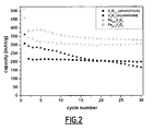
- Figure 2 shows the discharge capacities obtained for different thin layers of pure or Iron doped V 2 O 5 , deposited in absence of oxygen or under a partial pressure of oxygen of 14 %.
Landscapes
- Chemical & Material Sciences (AREA)
- Chemical Kinetics & Catalysis (AREA)
- Electrochemistry (AREA)
- General Chemical & Material Sciences (AREA)
- Engineering & Computer Science (AREA)
- Manufacturing & Machinery (AREA)
- Inorganic Chemistry (AREA)
- Organic Chemistry (AREA)
- Crystallography & Structural Chemistry (AREA)
- Battery Electrode And Active Subsutance (AREA)
- Compounds Of Iron (AREA)
Abstract
Description
- The invention relates to process of preparation of a substrate coated with a thin layer of an iron-doped vanadium oxide having a strong capacity and potentially usable in all-solid-state lithium microbatteries. The invention also relates to the preparation process of said substrates and microbafteries
- Since many years, the miniaturization of electronic systems is very spectacular. Their power consumptions have considerably decreased for many applications. More and more of apparatuses become portable or wandering. Batteries and accumulators follow the same evolution: they evolved from the R20 to the R6 format, and then appeared the button batteries, whose size regularly decreased as well. Since 15 to 20 years, many researchers worked on an even larger miniaturization and gave rise to the microbatteries.
- A microbattery is defined as a two-dimensional system comprising a positive electrode, an electrolyte (insulating layer) and a negative electrode. Such system generally has a thickness of some micrometers (µm) and a surface ranging from a few mm2 to several cm2, able to deliver weak currents, typically a few microamperes (µA). Microbatteries are prepared primarily by sputtering and by thermal evaporation on a generally flexible, very thin and perfectly tight support.
- The material of the positive electrode is first of all deposited by sputtering; its thickness generally varies from 2 to 5 µm. Then, the electrolyte is deposited by using the same technique with a thickness from 1 to 2 µm. Lastly, the material of the negative electrode, which is very generally pure lithium, is thermally evaporated. Finally, a last protective layer needs to be applied. The complete microbattery has a total thickness of approximately 10 µm to 15 µm (without taking into account the encapsulation).
- In order to be able to feed micro-electronics circuits for long periods, it is necessary to increase the density of energy of the microbatteries and consequently their capacity. Many studies are therefore currently carried out on thin layer positive electrode materials. Vanadium(V) oxide (V2O5), and more generally oxides of transition metals having a lamellar structure, arouse intensive research works, since they are more promising than the sulphides because of their greater chemical stability, higher potentials as compared to the Li/Li+ redox cell and larger discharge capacities.
- V2O5 is besides a material of choice as positive electrode in lithium microbatteries, now existing at the pre-development stage. This material makes it possible to obtain the strongest values of capacity which can reach 120 µAhcm-2µm-1, However, it presents the disadvantage of having a bad behaviour in cycling when crystallized; this phenomenon being all the more marked when the window of potential is broad (between about 3.7 and about 1.5 V).
- S. Maingot et al. (Journal of Power Sources, 54, (1995), 342-345) studied the origin of the improved cycling capability of sol-gel prepared Fe0.12V2O5.16 compared with V2Q5; however this iron-doped vanadium oxide is prepared from a V2O5 xerogel, requiring a further step of ionic exchange, and then thermal treatment, leading to a quite complex overall process, which is difficult to transpose to an industrial scale. Moreover, Fe0.12V2O5.16 is consequently obtained in a massive form or at least as thick layers (several hundreds of µm), however not easily in the form of thin layers and is therefore not appropriate for positive electrodes useable in microbatteries.
- An iron doped vanadium oxide doped of the formula FexV2O5 with x being respectively 0.12, 0.11 and in the range of 0,33 and 0,35 has been disclosed in the article of M.Y. Saidi et al., (Solid State lonics, North Holland Pub. Company, Amsterdam, NL, vol. 82, no.3, 1 December 1995, pages 203-207), the application
WI 93/12550 - There is therefore still a need for thin layers positive electrodes for use in microbatteries presenting an Improved behaviour in cycling.
- As such, a first objective of the present invention is to provide a specific material, useable in the form of thin layers appropriate to microbatteries which presents an improved behaviour in cycling as compared to vanadium oxide.
- The present inventors have now discovered that the above objectives are met, in whole or in part, with the present invention. Other objectives will appear in the following description of the invention.
- Particularly useful in the present invention is an iron-doped vanadium(V) oxide of formula FeyV2O5, wherein the FeN molar ratio varies from 0.015 to 0.4, preferably from 0.02 to 0.2, more preferably from 0.02 to 0.1. This molar ratio is determined by RBS (Rutherford Backscattering Spectroscopy), fixing the vanadium amount to a value of 2, and deducing the iron quantity. This corresponds to a positive real number "y" value of 0.03 to 0.8, preferably 0.04 to 0.4, more preferably from 0.04 to 0.2
- Preferably, the iron-doped vanadium(V) oxide of formula FeyV2O5 is in the form of a thin layer having a thickness in the range of about 50 nm to about 1000 nm, advantageously in the range of about 200 nm to about 800 nm, typically a thickness of about 500 nm. The thickness of the layer is typically measured with a mechanical profilometer.
- An aspect of the present invention is the process for the preparation of an iron-doped vanadium oxide of formula FeyV2O5, as defined above. The invention process uses the cathode co-pulverisation method, also referred to as cathode sputtering.
- The cathode pulverisation method involving one sole target is known in the art (see for example A. Gies et al., Solid Sate lonics, 176, (2005), 1627-1634).
- The principle of this method consists in ejecting matter starting from a material (the target) thanks to a flow of energy particles (Ar+) coming from a discharge gas, in a chamber under partial vacuum. The target is fixed on an electrode (cathode) bearing a negative tension. One second electrode (anode) is facing the cathode with a few centimetres between them.
- By applying a potential difference between the two electrodes, one causes the ionization of the discharge gas, thus creating a plasma containing electrons and positive ions attracted by the target. When they possess sufficient energy, they eject atoms which settle onto the substrates facing the target, thus forming a thin layer.
- According to the present invention, this known method has been improved and comprises the step of carrying out a simultaneous pulverisation starting from two different targets in one pulverisation chamber.
- More precisely, the process for the preparation of a substrate coated with a thin layer of iron-doped vanadium oxide of formula FeyV2O5 comprises the steps of:
- a) providing a first Vanadium-containing-target (the V-target) and a second Iron-containing target (the Fe-target) and fixing each of said first and second targets on a target-support;
- b) positioning said first and second targets in a pulverisation chamber, advantageously on a target-holder, the cathode;
- c) placing a substrate in the pulverisation chamber facing said two targets;
- d) filling the pulverisation chamber with a gas mixture comprising from 0 to 60-70 % of oxygen, and from 30-40 to 100 % of argon, until a pressure of 0.5 Pa to 2 Pa, advantageously 1 Pa is obtained in the pulverisation chamber;
- e) applying an electrical power Pv between the V-target and the substrate and an electrical power PFe between the Fe-target and the substrate; and allowing deposition to occur;
- f) removing the applied tension, opening the pulverisation chamber and recovering the substrate having a thin layer of FeyV2O5 on one of its surface.
- The target may be a metal or one of its oxides, or mixtures of more than one oxides, or a metal mixed with one or more of its oxides. In the above process, the targets may be on the one side V and/or V2O5, and on the other side Fe and/or Fe2O3. When oxides are used, both V2O5 and Fe2O3 targets are each prepared from high purity V2O5 and Fe2O3 powders, respectively. Each of the powders are advantageously mixed with an organic binder, such as camphor for example, at a ratio of about 0.5 weight% and about 3 weight%, preferably about 2 weight% relatively to the powder.
- Organic binders that are in a solid form may advantageously be dissolved before use into any appropriate solvent. As illustrative example, camphor, which is solid under ambient conditions, is dissolved in acetone before use.
- This mixture is then squeezed under an air pressure of approximately 30.103 kg during 5 min. The target is then sintered, generally at 400°C during 12 h then at 600°C during 10h, so as to obtain a dense target with good mechanical resistance. This heat treatment is also helpful for the removal of the organic binder, where appropriate.
- For the invention purpose, the V-target is preferably a pure vanadium target or a V2O5 target, and the Fe-target is a pure iron target or a Fe2O3 target. Still more preferably, the V-target is a V2O5 target, and the Fe-target is a Fe2O3 target.
- Oxygen and argon are preferably used as highly pure gases, for example a purity of about 99.5% for oxygen, and a purity of about 99.995% for argon. Pressure ratio of the gas mixture may vary depending on the nature of each of the targets, and good results are obtained with an oxygen ratio of about 10% to 20%, best results are obtained with an oxygen ratio of about 14%. Other gas mixtures are possible, without departing from the scope of the present invention.
- Fixing the targets onto their target supports may be realised by any known method known In the art, and for example, using a silicone-containing adhesive.
- Both targets fixed on their respective supports are positioned in the pulverisation chamber In a convergent manner, i.e. each converging towards the substrate where deposition will occur.
- The substrate is advantageously placed on a mobile plate, in order to make it possible to vary the distance between the substrate and the targets. According to a preferred embodiment of the process of the invention, the substrate is positioned at an equal distance of the V-target and the Fe-target.
- The substrate is advantageously a conductive substrate and should not lead to undesired reactions with the liquid electrolyte in the range of applied electrical potentials. Because of its appropriate electrical conductivity, especially for electrochemical studies, stainless steel is preferably used, although it does not constitute a limit to the present invention, but is rather cited as an example of usable substrates.
- According to a further embodiment, the pulverisation chamber is first emptied before it is filled with the gas mixture. Emptying the pulverisation chamber is conventionally carried out with a turbomolecular pump until a maximum is obtained, i.e. typically a vacuum of about 1.0.10-5 Pa to about 1.10-5 Pa, for example of about 5.10-5 Pa.
- Generally the ratio PFe / Pv ranges from 0.1 to 0.5, preferably from 0.2 to 0.4, and, for example, the applied power at the V-target (Pv) is set to a value ranging from 30 W to 70 W, typically the value is set to about 50 W, and the applied power at the Fe-target (PFe) is set to a value ranging from 5 W to 25 W, preferably from 10 W to 20 W.
- For example, fixing the applied tension to 50 W for the V-target and varying that applied to the Fe-target between 12 W and 20 W, It is possible to obtain compounds of the FeyV2O5 type whose Fe/V ratio determined by RBS varies from 0.015 to 0.40. The cathode co-pulverization technique thus makes it possible to prepare thin layers (generally in the range of 50 nm to 1000 nm, advantageously in the range of 200 nm to 800 nm, typically of about 500 nm) of various iron-doped vanadium oxide materials, the chemical compositions of which are not disclosed in the prior art.
- According to another advantageous feature of the process of the invention, a pre-pulverisation is carried out for a sufficient period time in order to ensure a thorough cleaning of the target surface before the actual deposit. Such pre-pulverisation may, for example, be carried out for several minutes to a couple of hours, generally for about one hour. Deposit, as well as pre-pulverisation, is preferably carried out at ambient temperature, i.e. without heating the substrate.
- The deposit of thin layered iron-doped vanadium oxide is realised by application of a power between both targets and the substrate, as previously described, generally during a period of time ranging from one to several hours, preferably from 1 to 12 hours, depending of the desired final thickness of the iron-doped vanadium oxide. As illustrative example only, deposit is carried out for 6 hours, when an iron-doped vanadium oxide having a thickness of about 500 nm is intended to be obtained.
- The cathode co-pulverisation process according to the present invention has the advantage of making it possible to reach a broad range of compositions by using only two targets. It is indeed possible to easily control the content (i.e. the "y" value) of doping element (Fe) in the thin layers by only varying the ratio of the electrical powers applied to both the targets.
- Still a further aspect of the present invention is a substrate coated with a thin layer of iron-doped vanadium (V) oxide of formula FeyV2O5 obtainable by the process according to the invention, wherein y is a positive real number in the range of 0.03 to 0.8, preferably in the range of 0.04 to 0.4, more preferably in the range 0.04 to 0.2. The thickness of the layer is in the range of about 50 nm to about 1000 nm, advantageously in the range of about 200 nm to about 800 nm, typically the thickness is about 500 nm.
- As a comparison, using a conventional technique of cathode sputtering using a single target, would require the preparation of a great number of targets with various FeyV2O5 compositions. Moreover, the outputs of pulverization of the elements constituting the target being different, the content of iron within the thin layers (the composition of which being very often different from the composition of the initial target) would be very difficult to control.
- Also the process of the present invention represents a valuable solution in terms of time saving, since the preparation of only one Fe-containing target and one V-containing target is necessary with the cathode co-pulverization technique, instead of preparing a great number of targets of different compositions, in the case of a conventional cathode sputtering technique.
- It should also be noted that, no substantial difference in terms of deposit rate between the traditional technique of cathode sputtering and the co-pulverization technique could be assessed, for a given power applied to the V-target.
- The inventors have surprisingly discovered that thin layers of V2O5 doped with iron of formula FeyV2O5, wherein y is as defined above, are effective to increase the electrochemical performances of positive electrodes, both in terms of capacity and behaviour in cycling.
- A further aspect is therefore the use as positive electrode comprising at least one layer of iron-doped vanadium (V) oxide of formula FeyV2O5, wherein y is a positive real number in the range of 0.03 to 0.8, preferably in the range of 0.04 to 0.4, more preferably in the range 0.04 to 0.2, and the thickness of the layer is in the range of about 50 nm to about 1000 nm, advantageously in the range of about 200 nm to about 800 nm, typically the thickness is about 500 nm.
- The positive electrode of iron-doped vanadium (V) oxide of formula FeyV2O5 of the present invention may be conventionally used in a great number of applications known in the art, and for example as positive electrode in batteries, especially microbatteries, as active electrode in electrochromic systems, as well as In catalysis and anti-static applications, and the like.
- According to a preferred feature of the Invention, thin layers of iron-doped vanadium (V) oxide of formula FeyV2O5 are useful as positive electrodes in microbatteries. In such microbatteries, the electrolyte and the negative electrode are those commonly used in the art.
- As non limiting examples, the electrolyte may be chosen from among lithium borates, lithium oxides, lithium sulphates, lithium phosphates, and the like and mixtures thereof, said electrolyte optionally further containing nitrogen, as is the case for example with Lison or Lipon, which is lithium sulphate or phosphate respectively, a portion of the oxygen atoms being replaced by nitrogen atoms.
- As non limiting examples, the negative electrode may be chosen from among lithium, optionally together with one or more materials chosen from among carbon, silicon, germanium, tin and any other material able to form an alloy with lithium. Most preferably, the negative electrode is a lithium electrode.
- When used as a positive electrode in microbatteries, the thin layer of iron-doped vanadium (V) oxide is, according to a preferred embodiment, of formula FeyV2O5, wherein y is 0.04 or wherein y is 0.19.
- The following examples are provided for illustrative purpose only and do not intend to limit the present invention in any way.
- Thin layers of Fe0.19V2O5 are prepared by cathode co-pulverization using a TSD 250-RF apparatus from H.E.F. Group and two ceramic, i.e. sintered targets: a V2O5 target and a Fe2O3 target having both 50 mm in diameter. The targets are prepared starting from a commercial powder (Aldrich 99.99%). Each powder (approximately 15 g) is mixed with 2 weight% of camphor, diluted in acetone. This mixture Is then squeezed under an air pressure of approximately 30,000 kg during 5 min. Each target is then sintered at 400°C during 12 h then at 600°C during 10 h. This heat treatment makes it pos sible to obtain a dense target with good mechanical resistance.
- The targets are then fixed on the target-support with a silicone-containing adhesive. The two cathodes are positioned in a convergent manner and tilted to a fixed angle of 27.8° relative to the vertical direction, according to the intrinsic characteristics of the apparatus. The stainless steel substrates are placed in the pulverisation chamber on a mobile plate facing the targets, halfway of the two targets, at a distance of 8 cm away from the targets. The substrate support and the substrates are connected to earth.
- In order to carry out the deposits, the pulverisation chamber is emptied using a turbomolecular pump until a limit vacuum of about 5.10-5 Pa is obtained. Then a gas mixture made up of 86 % of argon (purity: 99.995 %) and of 14 % of oxygen (purity: 99.5 %) is introduced into the chamber in order to obtain a total pressure in the chamber of 1 Pa.
- Before deposit, a one hour pre-pulverisation is carried out in order to ensure a thorough cleaning of the target (extreme surface elimination) and so as to reach a constant pulverisation rate.
- A power of 50 W is applied to the V2O5 target and a power of 20 W for the Fe2O3 target. The deposit is carried out at ambient temperature, i.e. without heating the substrate during 6 h in order to obtain a thickness of about 500 nm.
- Thin layers of Fe0.04V2O5 are prepared according to a similar process to that disclosed in example 1, except that a power of 12 W is applied to the Fe2O3 target.
- For this electrochemical study, thin layers are deposited on stainless steel discs of 13 mm in diameter. The discs were previously polished, cleaned and dried. The thin layers generally have a thickness of about 500 nm. Metallic lithium, in the form of a disc of 10 mm in diameter and having a thickness of 0.3 mm, Is used as the negative electrode. The electrolyte is a molar solution of a lithium salt in an organic solvent (for example LIPF6 in a mixture of ethylene carbonate (EC) and dimethyl carbonate (DMC) 1:1. The electrochemical sequence is thus as follows: Li/ 1M LiPF6 (EC/DMC) I FeyV2O5.
- The two electrodes as well as the electrolyte are then put together in a glove box, under argon pressure, in a Teflon® container. In order to prevent electrical short-circuits, the electrodes are separated from each other with three layers of a separator consisting of glass fiber paper impregnated with liquid electrolyte, The Teflon® container is then paced into a glass container provided with electrical conductive pathways.
- The above tests are run in liquid electrolyte and are run according to a similar procedure with all-solid-state microbatteries.
- Electrochemical properties are assessed under golvanostatic conditions (an electrical tension is set and the electrical potential is monitored as a function of time) on a commercially available apparatus (Biologic VMP). Standard cycling is run between potential limits (3.7 V to 1.5 V/Li) with a current density of 15 µAcm-2 (i.e. a current of 20 µA). Standard cycling therefore corresponds to the following steps:
- a 4 hours' initial relaxation;
- a discharge up to 1.5 V/Li;
- a 2 hours' relaxation;
- a charge up to 3.7 V/Li; and
- a 2 hours' relaxation.
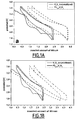
- In the case of a low content of iron (y = 0.04), the curve of discharge presents 4 plateaus at potentials equivalent to those of the thin layer of crystallized pure V2O6 (see
figure 1a ). The plateaus are shifted towards the greater amounts of inserted lithium. The greater the amount of inserted lithium, the greater the shift of the plateau. - As shown on
Figure 1a , the electrode with a thin layer of Fe0.04V2O5 allows a greater amount of lithium to be inserted, as compared with the electrode with a thin layer of V2O5, this effect being obtained as from the first cycle. This greater amount of inserted lithium also leads to a better discharge capacity. - Moreover, the amount of reversible lithium is greater during the following cycles. This clearly indicates an improved behaviour in cycling as compared to using an electrode with a thin layer of V2O5.
- With regard to the composition richer in iron (y = 0.19), the curve of first discharge does not present any more plateau but is characteristic of an amorphous material (see
figure 1b ). This was highlighted by X-ray diffraction analysis. -
Figure 2 shows the discharge capacities obtained for different thin layers of pure or Iron doped V2O5, deposited in absence of oxygen or under a partial pressure of oxygen of 14 %. - From
figure 2 , it is clear that the initial capacity is definitely higher (22% with the first cycle) for an iron-doped vanadium(V) oxide, wherein y = 0.04, than that for pure vanadium(V) oxide. - Moreover, a much better behaviour in cycling is observed. Indeed, the capacity is stabilized at the end of only 7 or 8 cycles to reach a value close to 300 mAh/g whereas at the end of 20 cycles, the capacity is close to 200 mAh/g for pure vanadium(V) oxide (amorphous or crystallized).
- With an iron-doped vanadium(V) oxide, wherein y = 0.19, the rate of intercalated lithium in the material is much higher, during the first discharge, than in the pure material, which results in an increase in the capacity of approximately 30 % as compared to crystallized V2O5 (see
figure 2 ). For this material, we also observe an excellent behaviour in cycling. After 10 cycles, the capacity is stabilized around 340 mAh/g.
Claims (15)
- A process for the preparation of a substrate coated with a thin layer of an Iron-doped vanadium(V) oxide comprising the steps of:a) providing a first Vanadium-containing-target and a second Iron-containing-target and fixing each of said first and second targets on a targets-support;b) positioning said first and second targets in a pulverisation chamber;c) placing a substrate in the pulverisation chamber facing said two targets;d) filling the pulverisation chamber with a gas mixture comprising from 0 to 60-70 % of oxygen, and from 30-40 to 100 % of argon, until a pressure of 0.5 Pa to 2 Pa is obtained in the pulverisation chamber;e) applying an electrical power Pv between the V-target and the substrate and an electrical power PFe between the Fe-target and the substrate; and hallowing deposition to occur;f) removing the applied tension, opening the pulverization chamber and recovering the substrate having a thin layer of iron-doped vanadium(V) oxide on one of its surface.
- The process of claim 1, wherein said first and second targets are positioned on a target-holder (cathode) In the pulverisation chamber.
- The process of claims 1 or 2, wherein a pressure of the gas mixture of 1 Pa is obtained in the pulverisation chamber.
- The process of anyone of claims 1 to 3, wherein both targets are positioned in the pulverisation chamber in a convergent manner.
- The process of anyone of claims 1 to 4, wherein the substrate is placed on a mobile plate.
- The process of anyone of claims 1 to 5, wherein the ratio PFe / Pv ranges from 0.1 to 0.5, preferably from 0.2 to 0.4, and the applied power at the V-target (Pv) is set to a value ranging from 30 W to 70 W, preferably 50 W, and the applied power at the Fe-target (PFe) is set to a value ranging from 5 W to 25 W, preferably from 10 W to 20 W.
- The process of anyone of claims 1 to 6, wherein a pre-pulverisatlon is carried out before applying said electrical power between the V-target and the substrate and said electrical power between the Fe-target and the substrate.
- The process of anyone of claims 1 to 7, said process being carried out at ambient temperature.
- Substrate coated with a thin layer of an iron-doped vanadium(V) oxide wherein the this layer has a thickness in the range of 50mm to 1000 nm obtainable by the process according to anyone of claims 1 to 8.
- Substrate according to claim 9, wherein the iron-doped vanadium(V) oxide has the following formula FeyV2O5, wherein y is a positive real number of from 0.03 to 0.8, preferably from 0.04 to 0.4, most preferably from 0.04 to 0.2.
- Substrate according to claim 9 or 10, wherein the thin layer has a thickness in the range of 200 nm to 800 nm, preferably from 500 nm.
- A microbattery comprising at least one substrate according to anyone of claims 9 to 12 as positive electrode.
- The microbattery of claim 12, further comprising an electrolyte chosen from among lithium borate, lithium oxide, lithium sulphate, lithium phosphate, and the like and mixtures thereof and/or an electrolyte containing nitrogen.
- The microbattery of claims 13, wherein the negative electrode is lithium, or lithium together with one or more materials chosen from among carbon, silicon, germanium, tin and any other material, able to form an alloy with lithium.
- The microbattery of anyone of claims 12 to 14, wherein the iron-doped vanadium(V) oxide is of formula FeyV2O5, wherein y is 0.04 or wherein y is 0.19.
Applications Claiming Priority (2)
| Application Number | Priority Date | Filing Date | Title |
|---|---|---|---|
| US1294207P | 2007-12-12 | 2007-12-12 | |
| PCT/EP2008/054357 WO2009074353A1 (en) | 2007-12-12 | 2008-04-10 | Iron-doped vanadium(v) oxides |
Publications (2)
| Publication Number | Publication Date |
|---|---|
| EP2220000A1 EP2220000A1 (en) | 2010-08-25 |
| EP2220000B1 true EP2220000B1 (en) | 2012-07-18 |
Family
ID=39666224
Family Applications (1)
| Application Number | Title | Priority Date | Filing Date |
|---|---|---|---|
| EP08736077A Not-in-force EP2220000B1 (en) | 2007-12-12 | 2008-04-10 | Iron-doped vanadium(v) oxides |
Country Status (3)
| Country | Link |
|---|---|
| US (1) | US20110020702A1 (en) |
| EP (1) | EP2220000B1 (en) |
| WO (1) | WO2009074353A1 (en) |
Families Citing this family (6)
| Publication number | Priority date | Publication date | Assignee | Title |
|---|---|---|---|---|
| WO2012001636A1 (en) * | 2010-06-29 | 2012-01-05 | Basf Se | Process for preparing doped or undoped alpha-vanadium oxide |
| WO2016100967A1 (en) * | 2014-12-19 | 2016-06-23 | Dimien Llc | Vanadium oxide compositions and systems and methods for creating them |
| CN109638257B (en) * | 2018-12-18 | 2022-04-26 | 中科廊坊过程工程研究院 | Composite vanadium pentoxide material and preparation method and application thereof |
| CN111900389B (en) * | 2020-05-26 | 2022-06-14 | 北京理工大学 | Fe2VO4Ordered mesoporous carbon composite material and application thereof |
| ES2985482B2 (en) | 2023-03-31 | 2025-03-27 | Univ Valencia | Mixed iron-vanadium oxide electrocatalytic electrode, process for its production and its use in hydrogen production |
| CN117878369B (en) * | 2023-11-29 | 2024-09-24 | 东华大学 | A flexible color-changing battery with reversible changes in multiple colors and a method for preparing the same |
Family Cites Families (2)
| Publication number | Priority date | Publication date | Assignee | Title |
|---|---|---|---|---|
| FR2685129B1 (en) * | 1991-12-13 | 1994-03-25 | Centre Nal Etudes Spatiales | USE OF VANADIUM OXIDE BRONZES WITH IRON AND / OR ALUMINUM AS CATHODE MATERIAL IN ELECTROCHEMICAL GENERATORS. |
| US6332900B1 (en) * | 1999-02-08 | 2001-12-25 | Wilson Greatbatch Ltd. | Physical vapor deposited electrode component and method of manufacture |
-
2008
- 2008-04-10 US US12/747,531 patent/US20110020702A1/en not_active Abandoned
- 2008-04-10 EP EP08736077A patent/EP2220000B1/en not_active Not-in-force
- 2008-04-10 WO PCT/EP2008/054357 patent/WO2009074353A1/en not_active Ceased
Also Published As
| Publication number | Publication date |
|---|---|
| WO2009074353A1 (en) | 2009-06-18 |
| US20110020702A1 (en) | 2011-01-27 |
| EP2220000A1 (en) | 2010-08-25 |
Similar Documents
| Publication | Publication Date | Title |
|---|---|---|
| CN113745651B (en) | Coated sulfide solid electrolyte and preparation method and application thereof | |
| CN109643784B (en) | Lithium borosilicate glass as electrolyte and electrode protection layer | |
| Uzakbaiuly et al. | Physical vapor deposition of cathode materials for all solid-state Li ion batteries: a review | |
| Nuli et al. | Nanocrystalline tin oxides and nickel oxide film anodes for Li-ion batteries | |
| Vinado et al. | Electrochemical and interfacial behavior of all solid state batteries using Li10SnP2S12 solid electrolyte | |
| US20170200952A1 (en) | LIPON COATINGS FOR HIGH VOLTAGE AND HIGH TEMPERATURE Li-ION BATTERY CATHODES | |
| EP3804020A1 (en) | Materials and methods for components of lithium batteries | |
| JP2003115293A (en) | Negative electrode for secondary battery, secondary battery using it, and method of manufacturing negative electrode | |
| JP2003524857A (en) | Lithium ion electrochemical battery | |
| Plichta et al. | The Rechargeable Li x TiS2/LiAlCl4/Li1− x CoO2 Solid‐State Cell | |
| US20110020702A1 (en) | Iron-doped vanadium(v) oxides | |
| WO2005076389A2 (en) | Self-contained, alloy type, thin film anodes for lithium-ion batteries | |
| Dai et al. | All-solid-state thin-film batteries based on lithium phosphorus oxynitrides | |
| Daramalla et al. | Superior electrochemical performance of amorphous titanium niobium oxide thin films for Li-ion thin film batteries | |
| EP3844317A1 (en) | Vapor deposition method for preparing an amorphous lithium borosilicate | |
| CN102870266A (en) | Solid electrolyte material, lithium battery, and manufacturing method for solid electrolyte material | |
| US20030207178A1 (en) | Method of preparing electrode composition having a carbon-containing-coated metal oxide, electrode composition and electrochemical cell | |
| WO2013180841A1 (en) | Bismuth-tin binary anodes for rechargeable magnesium-ion batteries | |
| US9911969B2 (en) | V2O5—LiBO2, V2O5—NiO—LiBO2 glasses and their composites obtained by nitrogen doping and reduced graphite oxide blending as cathode active materials | |
| Zhu et al. | Preparation and characteristics of LiFePO4 thin film by radio frequency magnetron sputtering for lithium microbatteries | |
| Polat et al. | SiAg film by magnetron sputtering for high reversible lithium ion storage anodes | |
| Seo et al. | New developments in solid electrolytes for thin-film lithium batteries | |
| Madinabeitia et al. | Growth parameters and diffusion barriers for functional high-voltage thin-film batteries based on spinel LiNi0. 5Mn1. 5O4 cathodes | |
| US11916227B2 (en) | Multilayer body and method for producing same | |
| Ugalde-Vázquez et al. | Effect of argon sputtering pressure on the electrochemical performance of LiFePO4 cathode |
Legal Events
| Date | Code | Title | Description |
|---|---|---|---|
| PUAI | Public reference made under article 153(3) epc to a published international application that has entered the european phase |
Free format text: ORIGINAL CODE: 0009012 |
|
| 17P | Request for examination filed |
Effective date: 20100610 |
|
| AK | Designated contracting states |
Kind code of ref document: A1 Designated state(s): AT BE BG CH CY CZ DE DK EE ES FI FR GB GR HR HU IE IS IT LI LT LU LV MC MT NL NO PL PT RO SE SI SK TR |
|
| AX | Request for extension of the european patent |
Extension state: AL BA MK RS |
|
| DAX | Request for extension of the european patent (deleted) | ||
| 17Q | First examination report despatched |
Effective date: 20101210 |
|
| GRAJ | Information related to disapproval of communication of intention to grant by the applicant or resumption of examination proceedings by the epo deleted |
Free format text: ORIGINAL CODE: EPIDOSDIGR1 |
|
| GRAP | Despatch of communication of intention to grant a patent |
Free format text: ORIGINAL CODE: EPIDOSNIGR1 |
|
| GRAS | Grant fee paid |
Free format text: ORIGINAL CODE: EPIDOSNIGR3 |
|
| GRAA | (expected) grant |
Free format text: ORIGINAL CODE: 0009210 |
|
| AK | Designated contracting states |
Kind code of ref document: B1 Designated state(s): AT BE BG CH CY CZ DE DK EE ES FI FR GB GR HR HU IE IS IT LI LT LU LV MC MT NL NO PL PT RO SE SI SK TR |
|
| REG | Reference to a national code |
Ref country code: GB Ref legal event code: FG4D |
|
| RIC1 | Information provided on ipc code assigned before grant |
Ipc: C01G 31/02 20060101AFI20120612BHEP Ipc: H01M 4/58 20100101ALI20120612BHEP Ipc: H01M 6/40 20060101ALI20120612BHEP |
|
| REG | Reference to a national code |
Ref country code: CH Ref legal event code: EP |
|
| REG | Reference to a national code |
Ref country code: AT Ref legal event code: REF Ref document number: 566955 Country of ref document: AT Kind code of ref document: T Effective date: 20120815 Ref country code: IE Ref legal event code: FG4D |
|
| REG | Reference to a national code |
Ref country code: NL Ref legal event code: T3 |
|
| REG | Reference to a national code |
Ref country code: DE Ref legal event code: R096 Ref document number: 602008017280 Country of ref document: DE Effective date: 20120913 |
|
| REG | Reference to a national code |
Ref country code: CH Ref legal event code: NV Representative=s name: KIRKER AND CIE S.A., CH |
|
| REG | Reference to a national code |
Ref country code: AT Ref legal event code: MK05 Ref document number: 566955 Country of ref document: AT Kind code of ref document: T Effective date: 20120718 |
|
| REG | Reference to a national code |
Ref country code: LT Ref legal event code: MG4D Effective date: 20120718 |
|
| PG25 | Lapsed in a contracting state [announced via postgrant information from national office to epo] |
Ref country code: HR Free format text: LAPSE BECAUSE OF FAILURE TO SUBMIT A TRANSLATION OF THE DESCRIPTION OR TO PAY THE FEE WITHIN THE PRESCRIBED TIME-LIMIT Effective date: 20120718 Ref country code: BE Free format text: LAPSE BECAUSE OF FAILURE TO SUBMIT A TRANSLATION OF THE DESCRIPTION OR TO PAY THE FEE WITHIN THE PRESCRIBED TIME-LIMIT Effective date: 20120718 Ref country code: AT Free format text: LAPSE BECAUSE OF FAILURE TO SUBMIT A TRANSLATION OF THE DESCRIPTION OR TO PAY THE FEE WITHIN THE PRESCRIBED TIME-LIMIT Effective date: 20120718 Ref country code: IS Free format text: LAPSE BECAUSE OF FAILURE TO SUBMIT A TRANSLATION OF THE DESCRIPTION OR TO PAY THE FEE WITHIN THE PRESCRIBED TIME-LIMIT Effective date: 20121118 Ref country code: FI Free format text: LAPSE BECAUSE OF FAILURE TO SUBMIT A TRANSLATION OF THE DESCRIPTION OR TO PAY THE FEE WITHIN THE PRESCRIBED TIME-LIMIT Effective date: 20120718 Ref country code: NO Free format text: LAPSE BECAUSE OF FAILURE TO SUBMIT A TRANSLATION OF THE DESCRIPTION OR TO PAY THE FEE WITHIN THE PRESCRIBED TIME-LIMIT Effective date: 20121018 Ref country code: LT Free format text: LAPSE BECAUSE OF FAILURE TO SUBMIT A TRANSLATION OF THE DESCRIPTION OR TO PAY THE FEE WITHIN THE PRESCRIBED TIME-LIMIT Effective date: 20120718 Ref country code: CY Free format text: LAPSE BECAUSE OF FAILURE TO SUBMIT A TRANSLATION OF THE DESCRIPTION OR TO PAY THE FEE WITHIN THE PRESCRIBED TIME-LIMIT Effective date: 20120718 |
|
| PG25 | Lapsed in a contracting state [announced via postgrant information from national office to epo] |
Ref country code: SE Free format text: LAPSE BECAUSE OF FAILURE TO SUBMIT A TRANSLATION OF THE DESCRIPTION OR TO PAY THE FEE WITHIN THE PRESCRIBED TIME-LIMIT Effective date: 20120718 Ref country code: GR Free format text: LAPSE BECAUSE OF FAILURE TO SUBMIT A TRANSLATION OF THE DESCRIPTION OR TO PAY THE FEE WITHIN THE PRESCRIBED TIME-LIMIT Effective date: 20121019 Ref country code: PT Free format text: LAPSE BECAUSE OF FAILURE TO SUBMIT A TRANSLATION OF THE DESCRIPTION OR TO PAY THE FEE WITHIN THE PRESCRIBED TIME-LIMIT Effective date: 20121119 Ref country code: PL Free format text: LAPSE BECAUSE OF FAILURE TO SUBMIT A TRANSLATION OF THE DESCRIPTION OR TO PAY THE FEE WITHIN THE PRESCRIBED TIME-LIMIT Effective date: 20120718 Ref country code: LV Free format text: LAPSE BECAUSE OF FAILURE TO SUBMIT A TRANSLATION OF THE DESCRIPTION OR TO PAY THE FEE WITHIN THE PRESCRIBED TIME-LIMIT Effective date: 20120718 Ref country code: SI Free format text: LAPSE BECAUSE OF FAILURE TO SUBMIT A TRANSLATION OF THE DESCRIPTION OR TO PAY THE FEE WITHIN THE PRESCRIBED TIME-LIMIT Effective date: 20120718 |
|
| PG25 | Lapsed in a contracting state [announced via postgrant information from national office to epo] |
Ref country code: RO Free format text: LAPSE BECAUSE OF FAILURE TO SUBMIT A TRANSLATION OF THE DESCRIPTION OR TO PAY THE FEE WITHIN THE PRESCRIBED TIME-LIMIT Effective date: 20120718 Ref country code: CZ Free format text: LAPSE BECAUSE OF FAILURE TO SUBMIT A TRANSLATION OF THE DESCRIPTION OR TO PAY THE FEE WITHIN THE PRESCRIBED TIME-LIMIT Effective date: 20120718 Ref country code: DK Free format text: LAPSE BECAUSE OF FAILURE TO SUBMIT A TRANSLATION OF THE DESCRIPTION OR TO PAY THE FEE WITHIN THE PRESCRIBED TIME-LIMIT Effective date: 20120718 Ref country code: EE Free format text: LAPSE BECAUSE OF FAILURE TO SUBMIT A TRANSLATION OF THE DESCRIPTION OR TO PAY THE FEE WITHIN THE PRESCRIBED TIME-LIMIT Effective date: 20120718 Ref country code: ES Free format text: LAPSE BECAUSE OF FAILURE TO SUBMIT A TRANSLATION OF THE DESCRIPTION OR TO PAY THE FEE WITHIN THE PRESCRIBED TIME-LIMIT Effective date: 20121029 |
|
| PLBE | No opposition filed within time limit |
Free format text: ORIGINAL CODE: 0009261 |
|
| STAA | Information on the status of an ep patent application or granted ep patent |
Free format text: STATUS: NO OPPOSITION FILED WITHIN TIME LIMIT |
|
| PG25 | Lapsed in a contracting state [announced via postgrant information from national office to epo] |
Ref country code: SK Free format text: LAPSE BECAUSE OF FAILURE TO SUBMIT A TRANSLATION OF THE DESCRIPTION OR TO PAY THE FEE WITHIN THE PRESCRIBED TIME-LIMIT Effective date: 20120718 Ref country code: IT Free format text: LAPSE BECAUSE OF FAILURE TO SUBMIT A TRANSLATION OF THE DESCRIPTION OR TO PAY THE FEE WITHIN THE PRESCRIBED TIME-LIMIT Effective date: 20120718 |
|
| 26N | No opposition filed |
Effective date: 20130419 |
|
| PG25 | Lapsed in a contracting state [announced via postgrant information from national office to epo] |
Ref country code: BG Free format text: LAPSE BECAUSE OF FAILURE TO SUBMIT A TRANSLATION OF THE DESCRIPTION OR TO PAY THE FEE WITHIN THE PRESCRIBED TIME-LIMIT Effective date: 20121018 |
|
| REG | Reference to a national code |
Ref country code: DE Ref legal event code: R097 Ref document number: 602008017280 Country of ref document: DE Effective date: 20130419 |
|
| PG25 | Lapsed in a contracting state [announced via postgrant information from national office to epo] |
Ref country code: MC Free format text: LAPSE BECAUSE OF FAILURE TO SUBMIT A TRANSLATION OF THE DESCRIPTION OR TO PAY THE FEE WITHIN THE PRESCRIBED TIME-LIMIT Effective date: 20120718 |
|
| REG | Reference to a national code |
Ref country code: IE Ref legal event code: MM4A |
|
| PG25 | Lapsed in a contracting state [announced via postgrant information from national office to epo] |
Ref country code: IE Free format text: LAPSE BECAUSE OF NON-PAYMENT OF DUE FEES Effective date: 20130410 |
|
| PG25 | Lapsed in a contracting state [announced via postgrant information from national office to epo] |
Ref country code: MT Free format text: LAPSE BECAUSE OF FAILURE TO SUBMIT A TRANSLATION OF THE DESCRIPTION OR TO PAY THE FEE WITHIN THE PRESCRIBED TIME-LIMIT Effective date: 20120718 |
|
| PG25 | Lapsed in a contracting state [announced via postgrant information from national office to epo] |
Ref country code: TR Free format text: LAPSE BECAUSE OF FAILURE TO SUBMIT A TRANSLATION OF THE DESCRIPTION OR TO PAY THE FEE WITHIN THE PRESCRIBED TIME-LIMIT Effective date: 20120718 |
|
| PG25 | Lapsed in a contracting state [announced via postgrant information from national office to epo] |
Ref country code: HU Free format text: LAPSE BECAUSE OF FAILURE TO SUBMIT A TRANSLATION OF THE DESCRIPTION OR TO PAY THE FEE WITHIN THE PRESCRIBED TIME-LIMIT; INVALID AB INITIO Effective date: 20080410 Ref country code: LU Free format text: LAPSE BECAUSE OF NON-PAYMENT OF DUE FEES Effective date: 20130410 |
|
| REG | Reference to a national code |
Ref country code: FR Ref legal event code: PLFP Year of fee payment: 9 |
|
| REG | Reference to a national code |
Ref country code: FR Ref legal event code: PLFP Year of fee payment: 10 |
|
| REG | Reference to a national code |
Ref country code: DE Ref legal event code: R082 Ref document number: 602008017280 Country of ref document: DE Representative=s name: LAVOIX MUNICH, DE |
|
| REG | Reference to a national code |
Ref country code: FR Ref legal event code: PLFP Year of fee payment: 11 |
|
| PGFP | Annual fee paid to national office [announced via postgrant information from national office to epo] |
Ref country code: CH Payment date: 20200424 Year of fee payment: 13 Ref country code: NL Payment date: 20200313 Year of fee payment: 13 Ref country code: FR Payment date: 20200430 Year of fee payment: 13 Ref country code: DE Payment date: 20200408 Year of fee payment: 13 |
|
| PGFP | Annual fee paid to national office [announced via postgrant information from national office to epo] |
Ref country code: GB Payment date: 20200427 Year of fee payment: 13 |
|
| REG | Reference to a national code |
Ref country code: DE Ref legal event code: R119 Ref document number: 602008017280 Country of ref document: DE |
|
| REG | Reference to a national code |
Ref country code: NL Ref legal event code: MM Effective date: 20210501 |
|
| GBPC | Gb: european patent ceased through non-payment of renewal fee |
Effective date: 20210410 |
|
| PG25 | Lapsed in a contracting state [announced via postgrant information from national office to epo] |
Ref country code: GB Free format text: LAPSE BECAUSE OF NON-PAYMENT OF DUE FEES Effective date: 20210410 Ref country code: FR Free format text: LAPSE BECAUSE OF NON-PAYMENT OF DUE FEES Effective date: 20210430 Ref country code: DE Free format text: LAPSE BECAUSE OF NON-PAYMENT OF DUE FEES Effective date: 20211103 Ref country code: CH Free format text: LAPSE BECAUSE OF NON-PAYMENT OF DUE FEES Effective date: 20210430 Ref country code: LI Free format text: LAPSE BECAUSE OF NON-PAYMENT OF DUE FEES Effective date: 20210430 |
|
| PG25 | Lapsed in a contracting state [announced via postgrant information from national office to epo] |
Ref country code: NL Free format text: LAPSE BECAUSE OF NON-PAYMENT OF DUE FEES Effective date: 20210501 |