EP2219884B1 - Hybrid cords for tire reinforcement - Google Patents
Hybrid cords for tire reinforcement Download PDFInfo
- Publication number
- EP2219884B1 EP2219884B1 EP08858073A EP08858073A EP2219884B1 EP 2219884 B1 EP2219884 B1 EP 2219884B1 EP 08858073 A EP08858073 A EP 08858073A EP 08858073 A EP08858073 A EP 08858073A EP 2219884 B1 EP2219884 B1 EP 2219884B1
- Authority
- EP
- European Patent Office
- Prior art keywords
- core
- sheath
- aramid
- cord
- steel
- Prior art date
- Legal status (The legal status is an assumption and is not a legal conclusion. Google has not performed a legal analysis and makes no representation as to the accuracy of the status listed.)
- Not-in-force
Links
Images

Classifications
-
- B—PERFORMING OPERATIONS; TRANSPORTING
- B60—VEHICLES IN GENERAL
- B60C—VEHICLE TYRES; TYRE INFLATION; TYRE CHANGING; CONNECTING VALVES TO INFLATABLE ELASTIC BODIES IN GENERAL; DEVICES OR ARRANGEMENTS RELATED TO TYRES
- B60C9/00—Reinforcements or ply arrangement of pneumatic tyres
- B60C9/0042—Reinforcements made of synthetic materials
-
- B—PERFORMING OPERATIONS; TRANSPORTING
- B60—VEHICLES IN GENERAL
- B60C—VEHICLE TYRES; TYRE INFLATION; TYRE CHANGING; CONNECTING VALVES TO INFLATABLE ELASTIC BODIES IN GENERAL; DEVICES OR ARRANGEMENTS RELATED TO TYRES
- B60C9/00—Reinforcements or ply arrangement of pneumatic tyres
- B60C9/005—Reinforcements made of different materials, e.g. hybrid or composite cords
-
- D—TEXTILES; PAPER
- D02—YARNS; MECHANICAL FINISHING OF YARNS OR ROPES; WARPING OR BEAMING
- D02G—CRIMPING OR CURLING FIBRES, FILAMENTS, THREADS, OR YARNS; YARNS OR THREADS
- D02G3/00—Yarns or threads, e.g. fancy yarns; Processes or apparatus for the production thereof, not otherwise provided for
- D02G3/44—Yarns or threads characterised by the purpose for which they are designed
- D02G3/48—Tyre cords
-
- D—TEXTILES; PAPER
- D07—ROPES; CABLES OTHER THAN ELECTRIC
- D07B—ROPES OR CABLES IN GENERAL
- D07B1/00—Constructional features of ropes or cables
- D07B1/06—Ropes or cables built-up from metal wires, e.g. of section wires around a hemp core
- D07B1/0606—Reinforcing cords for rubber or plastic articles
- D07B1/062—Reinforcing cords for rubber or plastic articles the reinforcing cords being characterised by the strand configuration
-
- D—TEXTILES; PAPER
- D10—INDEXING SCHEME ASSOCIATED WITH SUBLASSES OF SECTION D, RELATING TO TEXTILES
- D10B—INDEXING SCHEME ASSOCIATED WITH SUBLASSES OF SECTION D, RELATING TO TEXTILES
- D10B2331/00—Fibres made from polymers obtained otherwise than by reactions only involving carbon-to-carbon unsaturated bonds, e.g. polycondensation products
- D10B2331/02—Fibres made from polymers obtained otherwise than by reactions only involving carbon-to-carbon unsaturated bonds, e.g. polycondensation products polyamides
- D10B2331/021—Fibres made from polymers obtained otherwise than by reactions only involving carbon-to-carbon unsaturated bonds, e.g. polycondensation products polyamides aromatic polyamides, e.g. aramides
-
- Y—GENERAL TAGGING OF NEW TECHNOLOGICAL DEVELOPMENTS; GENERAL TAGGING OF CROSS-SECTIONAL TECHNOLOGIES SPANNING OVER SEVERAL SECTIONS OF THE IPC; TECHNICAL SUBJECTS COVERED BY FORMER USPC CROSS-REFERENCE ART COLLECTIONS [XRACs] AND DIGESTS
- Y10—TECHNICAL SUBJECTS COVERED BY FORMER USPC
- Y10T—TECHNICAL SUBJECTS COVERED BY FORMER US CLASSIFICATION
- Y10T152/00—Resilient tires and wheels
- Y10T152/10—Tires, resilient
Definitions
- the present invention relates to the field of hybrid cords for reinforcement of tires, in particular hybrid cords comprising steel and p -aramid filaments.
- hybrid cords for reinforcing tires comprising steel strands wound with p -aramid strands, both with a steel core and a p-aramid core.
- US 4,176,705 describe wire reinforcement cords for tires.
- the cords consist of a p -aramid core, and steel strands comprised of steel filaments twisted together are disposed about the core.
- the invention provides a hybrid cord for reinforcing tires, the cord comprising: a core of at least one p-aramid filament; and a sheath of steel strands helically wound around the p-aramid filament; wherein the p- aramid filament has modulus greater than about 6.5 and up to about 10.8 N/dTex.
- the invention provides a tire reinforcement structure comprising a hybrid cord of the invention.
- the invention provides a tire comprising a hybrid cord of the invention.
- the invention provides a method for manufacturing a hybrid cord, comprising the steps of providing a core of at least one p-aramid filament having a modulus greater than about 6.5 N/dTex and wrapping the core with a plurality of steel strands, so as to form a sheath.
- the invention provides a method for manufacturing a tire reinforcement structure comprising a step of incorporation of a hybrid cord of the invention in a matrix.
- the invention provides a method for manufacturing a reinforced tire comprising a step of incorporating a hybrid cord of the invention within the tire.
- the hybrid cord of the invention has a core that comprises at least one continuous high-modulus p -aramid filament wherein the modulus is typically between 6.5 and 10.8 N/dTex; for example 7 or greater such as 7 to 10.8 N/dTex; or additionally 6.5 to 8 N/dTex.
- the high modulus p -aramid can be achieved as described, for example, in US 3869,430 by fiber spinning through hot chambers, tensile devices and lowering spinning speed to raise the crystallinity and provide the desired crystal orientation.
- the elongation at break of the core and the sheath filaments is closely matched, so that under a breaking load (i.e. destructive tensile test), the core and the sheath filaments tend to break at essentially the same elongation or, more simply, at the same time.
- One or more yarns may be used for the core.
- the core may have a round or elliptical cross-section before being wound with the sheath filaments, however, it can also have a more complex shape, such as a multi-lobed shape or a star shape.
- a more complex shape such as a multi-lobed shape or a star shape.
- the core may consist of a single p -aramid filament, or it may consist of a yarn made by twisting together multiple p -aramid filaments. It is also possible for the core to consist of two or more p -aramid filaments that are not twisted together, i.e. which are in a free relationship, or it may consist of two or more aramid yarns which are either twisted together or free.
- any diameter or linear density yarn may be used for the core.
- linear density is related directly to diameter and so the two expressions may be used interchangeably.
- the linear density of the core strand chosen depends on the final diameter of hybrid cord that is desired.
- An example of a yarn that can be used as the core strand is a p- aramid yarn having a linear density in the range of about 1000-5000 dtex, or about 1500-4000 dtex. Commercially available yarns having linear densities in the range of about 1600-3200 dtex are suitable.
- the core yarn may consist of multiple p -aramid filaments that are twisted together to form the yarn of the desired dTex. For example, in a typical yarn having a linear density of about 1580 dTex, there are about 1000 filaments. In a typical yarn having a linear density of about 3160 dTex, there are about 1333 to 2000 filaments.
- Each sheath strand may consist of a continuous single steel wire or it may consist of multiple continuous wires twisted together to form a cable.
- the wires have an elliptical or circular cross-section.
- the wires are typically coated with a coating conferring affinity for rubber, especially a coating which can react with sulphur atoms in the rubber, such as, for example, copper, zinc and alloys of such metals, for example brass.
- the diameter of the sheath strands will influence the final structure of the hybrid cord.
- a typical diameter for steel wires used in the hybrid cord of the invention for tire reinforcement is in the range of about 0.15 mm to 0.25 mm, for example 0.175 mm. Also preferred is so-called "fine steel", which has a diameter in the range of about 0.04 mm to 0.125 mm.
- Cords made with fine steel sheaths are particularly suited for passenger car tire belts or motorcycle tire belts. If fine steel wires are used as the sheath, it is preferred to use a core of about 1600 dtex. If wires having a diameter of about 0.15 mm or more are used in the sheath, the core should preferably be made with one or two p-aramid yarns with each yarn being of about 3200 dTex.
- a core d / 2 ⁇ cos ⁇ 2 X ⁇ - N ⁇ ⁇ - sin ⁇ cos ⁇ X 1 / tan ⁇ 2 - Ncos ⁇ X ⁇ / 2 - ⁇ - sin ⁇ cos ⁇
- d is the diameter of the sheath strands
- ⁇ is the helical angle
- N is the number of sheath strands
- ⁇ ⁇ /N.
- the strand diameter d is expressed in mm
- ⁇ is expressed in radians, so that the resulting A core value is in mm 2 .
- the filling ratio can be calculated by dividing the actual core cross section by the calculated A core value.
- the Core Fill Factor is the fraction of the effective yarn cross section occupied by the aramid fibers on the total yarn cross section which also includes the small voids existing between the closely packed fibers.
- the external sheath may consist of as few as two steel strands, but may have less than twenty steel strands.
- the diameters of steel strands are about 0.08 to 0.25 mm or about 0.08 to 0.125 mm for passenger car tire or motorcycle tire belt applications and about 0.15 to 0.2 for truck tire belt and carcass applications.
- hybrid cords of the invention are described below. These cords all have filling ratios of 1.0:
- the "expected tensile strength" has been calculated assuming that the tensile strength of both core and sheath is fully exploited and that the two components break together while the steel sheath is in the plastic flow zone of the elasto-plastic model.
- Cords 1, 2, 3 and 4 which have sheaths made of "fine steel", may be used as belt materials for high-performance passenger car tires.
- Such cords when embedded in a polymer matrix (e.g. rubber), yield tires having an increased area of the "footprint patch” (i.e. the area of the tire in contact with the road), which leads to an improvement in the behaviour of the belt structure and a reduction of the tangential stresses and strains in the tread elements during high-stress conditions, such as those encountered during so-called "hard-handling” tests on racing tracks.
- the same cords i.e. using fine steel
- Cords 5, 6 and 7, which use conventional wire diameters in their sheaths, are particularly suited to use in truck tire belts and carcasses.
- the hybrid cord of the invention is particularly suited for use in reinforcing belts in passenger tires, truck tires and carcasses and high performance motorcycle tires.
- the use of p-aramid as the core material in the cord of the invention reduces weight in the tire and improves rolling resistance. Furthermore, it reduces corrosion, since p-aramid is not susceptible to corrosion.
- the cord is incorporated into a matrix to form a tire reinforcement structure, in the form of a carcass, a bead reinforcement chafer (a composite strip for low sidewall reinforcement), or of a belt strip.
- the matrix can be any polymeric material which can partially or totally embed the cord of the invention and keep multiple cords in a fixed orientation and placement with respect to each other. Typical materials are thermoset materials, such as rubbers; however it is also possible to use thermoplastic materials, such as thermoplastic vulcanisates and copolyetheresters.
- the tire reinforcement structure is then fitted into the structure of the tire, typically under the tread. For belt reinforcement structures, the belt runs around the circumference of the tire, under the tread, or around the rim(s) of the tire.
- a chosen number of steel strands are cabled or spirally wrapped around the high modulus p -aramid core.
- the steel strands may each be composed of a desired number of steel filaments or wires, which are twisted together to form a cable.
- a standard cabling machine for steel cord production can be used to produce the hybrid cord.
- the filling ratio may be about 0.85 to 1.15 or about 0.95 to 1.05.
- the filling ratio is too low, it is difficult to get a regular geometry of the hybrid cord, and there will be no mechanical coupling between the core and the sheath. This means that the core can slip inside the sheath, impairing cord strength.
- the sheath strands may cover at least 85% of the core, or at least 90% of the core, or even at least 95% of the core. With a filling ratio of 1.15, the steel sheath will cover 93.25% of the core surface.
- the geometry of the cross-section is "regular" (see Fig. 1 ), i.e. the core 2 essentially completely fills the star-shaped gap inside the sheath wires 4.
- the cross-section of the hybrid cord 10 has 8 wires 4 spirally wrapped around the aramid core 2 with each sheath wire 4 disposed with its cross-sectional center on the vertices of a regular polygon.
- the aramid core is shown as being squeezed into a complex shape (in this depiction, a star) by the sheath filaments.
- This example cord represents a practical embodiment of Cord 5, mentioned in the general description.
- Commercially available 3160 dTex yarn was used as the core.
- the filling ratio was 0.9969.
- the expected total load at break if the sheath and core are optimally exploited (as calculated) was 1452 N.
- This example cord represents a practical embodiment of Cord 6, mentioned in the general description.
- Commercially available 3160 dTex yarn was used as the core.
- the filling ratio was 0.9646.
- the expected total load at break if the sheath and core are optimally exploited (as calculated) was 1324 N.
- This example cord represents a practical embodiment of Cord 7, mentioned in the general description.
- Commercially available 3160 dTex yarn was used as the core.
- the filling ratio was 1.0016.
- the expected total load at break if the sheath and core are optimally exploited (as calculated) was 2290 N
- Wire_breaking_load N Steel_tensile_strength N / mm 2 * 1 / 4 * ⁇ * d mm 2
- Examples 1, 2 and 3 are examples of hybrid cords according to the invention. All of them show excellent performance in terms of total load at break, and exploit both the core and the sheath. It is apparent that the experimental tensile strength values ("Actual load at break”), resulting from the average of 5 samples, are in good agreement with the theoretical values (“Calculated load at break”). The agreement is 99.31%, 100.68% and 93.93%, for examples 1, 2 and 3, respectively. The fact that the breaking strength of the larger cord (Example 3) falls a bit short of the expectations is believed to be due to the use of a twisted pair core instead of a single yarn.
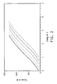
- Fig. 2 shows the tensile strength data for Example 2 (x-axis: Elongation in %, y-axis: Force in N).
- the smooth curve indicates the desired contemporaneous breaking of the core and sheath.
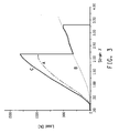
- Fig. 3 shows the behaviour of a conventional cord made with standard low modulus p-aramid.
- strain in % On the x-axis is strain in %, on the y-axis is load in N.
- the cord is a construction comprising a 3333 dTex standard p -aramid core, surrounded by 12 wires of diameter 0.2 mm.
- Curve C shows the total load on the specimen.
- Curve B is the tensile plot for the core yarn (i.e. without sheath), and Curve A is the difference between Curve C and Curve B, corresponding to the contribution of the steel sheath. It is apparent that the steel sheath wires break long before the p -aramid core is fully loaded.
- the calculated strength of the construction is 1592 N, whereas the experimental value is 1298 N (81.54%).
- the p -aramid core contribution to the strength is only 318 N, corresponding to only 51.88% of the pure core strength.
- the exploitation of the p -aramid core strength is around 50%, when a standard p -aramid core is used.
- a high modulus p -aramid is used; almost 100% of the core strength is exploited.
Abstract
Description
- The present invention relates to the field of hybrid cords for reinforcement of tires, in particular hybrid cords comprising steel and p-aramid filaments.
- It is known to make hybrid cords for reinforcing tires comprising steel strands wound with p-aramid strands, both with a steel core and a p-aramid core.
-
US 5,551,498 describes hybrid cords having a core of two p-aramid strands twisted together and an outer layer or sheath of six steel strands or filaments surrounding the core. Also described are hybrid cords consisting of a core consisting of three steel strands and a layer consisting of four p-aramid strands surrounding the core. -
US 4,176,705 describe wire reinforcement cords for tires. The cords consist of a p-aramid core, and steel strands comprised of steel filaments twisted together are disposed about the core. - It is known that steel wires have a lower breaking extension than filaments of aromatic polyamide (aramid). As a consequence, prior art composite reinforcing cords can be exposed only to loads at which the cord's extension does not exceed the breaking extension of the steel wire strands. If this limit load is exceeded, the steel wires rupture and the entire load is taken up by the aramid core which in turn immediately exceeds its own breaking elongation and ruptures as well. In other words, known composite cords break when the extension corresponds to the breaking extension of its steel wire component, in spite of the fact that the latter is distinctly below the breaking elongation of the polyamide core.
- Such premature breakage of the steel wires is described in
US 4,807,680 , which discloses a tire including a hybrid cord consisting of a core of multiple p-aramid filaments surrounded by steel filaments that are wound around the core. The proposed solution is to use almost rectangular cross-section wires, which have a higher elongation at break than corresponding regular round cross-section wires. Hybrid cords using rectangular cross-section wires, are also described in patentUS 4, 878, 343. - A need remains for hybrid cords which make full use of the p-aramid component.
- The invention is defined by the features of the claims.
-
-
Figure 1 depicts the cross-section of a hybrid cord in one embodiment of the invention. -
Figure 2 shows the tensile strength data for Example 2 as one embodiment of the hybrid cord of the invention. -
Figure 3 shows the mechanical behaviour of a conventional cord made with a core of standard p-aramid. -
- "Strand" as used herein means a continuous band of material, either aramid or steel, which band of material may comprise either a single filament or multiple filaments twisted together to form a yarn (aramid) or cable (steel).
- "Filament" as used herein means a relatively flexible, macroscopically homogeneous body having a high ratio of length to width across its cross-sectional area perpendicular to its length. The filament cross section can be any shape, but is typically circular. Herein, the term "fiber", with respect to aramid, is used interchangeably with the term "filament". The term "wire", with respect to steel, may also be used interchangeably with the term "filaments".
- "Wire" as used herein means a continuous body of steel having a high ratio of length to width across its cross-sectional area perpendicular to its length.
- "Yarn" as used herein means a strand comprising multiple filaments twisted together.
- "Cable" as used herein means a strand comprising multiple wires twisted together.
- "Diameter" in reference to a filament, strand, yarn or cable is the diameter of the smallest circle that can be drawn to circumscribe the entire cross-section of the filament, strand, yarn or cable.
- "Denier" the weight in grams per 9,000 m length of filament, strand, yarn or cable.
- "Tex" the weight in grams of one kilometre of filament, strand, yarn or cable.
- "Decitex" one tenth of a Tex, abbreviated as dTex.
- "Helical angle" means the angle formed by the path of a sheath strand and the major axis of the core. The expression helix angle is used equivalently.
- "Lay length" means the length, measured on the sheath axis, corresponding to a full turn of sheath around the core.
- It has been found that when a hybrid cord is made using a core of high modulus p-aramid surrounded by steel strands, best use is made of the p-aramid strength and hybrid cords are produced in which the breaking load value is close to the sum of that of the p-aramid and the steel separately.
- In a first embodiment, the invention provides a hybrid cord for reinforcing tires, the cord comprising: a core of at least one p-aramid filament; and a sheath of steel strands helically wound around the p-aramid filament; wherein the p-aramid filament has modulus greater than about 6.5 and up to about 10.8 N/dTex.
- In a second embodiment, the invention provides a tire reinforcement structure comprising a hybrid cord of the invention.
- In a third embodiment, the invention provides a tire comprising a hybrid cord of the invention.
- In a one aspect, the invention provides a method for manufacturing a hybrid cord, comprising the steps of providing a core of at least one p-aramid filament having a modulus greater than about 6.5 N/dTex and wrapping the core with a plurality of steel strands, so as to form a sheath.
- In another aspect, the invention provides a method for manufacturing a tire reinforcement structure comprising a step of incorporation of a hybrid cord of the invention in a matrix.
- In yet another aspect, the invention provides a method for manufacturing a reinforced tire comprising a step of incorporating a hybrid cord of the invention within the tire.
- In one embodiment, the hybrid cord of the invention has a core that comprises at least one continuous high-modulus p-aramid filament wherein the modulus is typically between 6.5 and 10.8 N/dTex; for example 7 or greater such as 7 to 10.8 N/dTex; or additionally 6.5 to 8 N/dTex. The high modulus p-aramid can be achieved as described, for example, in
US 3869,430 by fiber spinning through hot chambers, tensile devices and lowering spinning speed to raise the crystallinity and provide the desired crystal orientation. - By using high modulus p-aramid, the elongation at break of the core and the sheath filaments is closely matched, so that under a breaking load (i.e. destructive tensile test), the core and the sheath filaments tend to break at essentially the same elongation or, more simply, at the same time. One or more yarns may be used for the core.
- The core may have a round or elliptical cross-section before being wound with the sheath filaments, however, it can also have a more complex shape, such as a multi-lobed shape or a star shape. Once the core is wound with the sheath filaments, it will be "squeezed" by the sheath filaments, and will typically take on a more complex cross-sectional shape, such as the "star shape" in
Fig. 1 . - The core may consist of a single p-aramid filament, or it may consist of a yarn made by twisting together multiple p-aramid filaments. It is also possible for the core to consist of two or more p-aramid filaments that are not twisted together, i.e. which are in a free relationship, or it may consist of two or more aramid yarns which are either twisted together or free.
- Essentially any diameter or linear density yarn may be used for the core. For homogenous yarns, linear density is related directly to diameter and so the two expressions may be used interchangeably. The linear density of the core strand chosen depends on the final diameter of hybrid cord that is desired. An example of a yarn that can be used as the core strand is a p-aramid yarn having a linear density in the range of about 1000-5000 dtex, or about 1500-4000 dtex. Commercially available yarns having linear densities in the range of about 1600-3200 dtex are suitable.
- The core yarn may consist of multiple p-aramid filaments that are twisted together to form the yarn of the desired dTex. For example, in a typical yarn having a linear density of about 1580 dTex, there are about 1000 filaments. In a typical yarn having a linear density of about 3160 dTex, there are about 1333 to 2000 filaments.
- Each sheath strand may consist of a continuous single steel wire or it may consist of multiple continuous wires twisted together to form a cable. The wires have an elliptical or circular cross-section. The wires are typically coated with a coating conferring affinity for rubber, especially a coating which can react with sulphur atoms in the rubber, such as, for example, copper, zinc and alloys of such metals, for example brass.
- The diameter of the sheath strands will influence the final structure of the hybrid cord. A typical diameter for steel wires used in the hybrid cord of the invention for tire reinforcement is in the range of about 0.15 mm to 0.25 mm, for example 0.175 mm. Also preferred is so-called "fine steel", which has a diameter in the range of about 0.04 mm to 0.125 mm. Cords made with fine steel sheaths are particularly suited for passenger car tire belts or motorcycle tire belts. If fine steel wires are used as the sheath, it is preferred to use a core of about 1600 dtex. If wires having a diameter of about 0.15 mm or more are used in the sheath, the core should preferably be made with one or two p-aramid yarns with each yarn being of about 3200 dTex.
- In providing embodiments of a hybrid cord according to the invention the following parameters are considered:
- The number of sheath strands, N;
- The diameter of the sheath strands, d;
- The diameter or linear density of the core strand or strands;
- The filling ratio;
- The helical angle θ or the lay length. These two parameters are not independent since the lay length is equal to π * dc/tan θ, where dc is the diameter of the circle passing through the centers of the sheath strands. The filling ratio is defined as the ratio between the actual cross-sectional area of the core and the area available for the core. In the hybrid cords of the invention, it is desired to have a filling ratio of from about 0.85 to 1.15, but preferably about 1.
- For helical angles not exceeding 20°, the approximate total area available for the core (Acore) is given empirically by equation (1):

wherein d is the diameter of the sheath strands, θ is the helical angle, N is the number of sheath strands, and β = π/N. The strand diameter d is expressed in mm, and β is expressed in radians, so that the resulting Acore value is in mm2. - The filling ratio can be calculated by dividing the actual core cross section by the calculated Acore value. The actual core cross section can be measured by means of optical or electronic microscopy or, alternatively, can be calculated as:

wherein, in case of p-aramid yarns made with round cross-section fibers, the Fiber Specific Gravity is equal to 1.44 and the Core Fill Factor has been experimentally found to be equal to 0.74768. The Core Fill Factor is the fraction of the effective yarn cross section occupied by the aramid fibers on the total yarn cross section which also includes the small voids existing between the closely packed fibers. - The external sheath may consist of as few as two steel strands, but may have less than twenty steel strands.
- The diameters of steel strands are about 0.08 to 0.25 mm or about 0.08 to 0.125 mm for passenger car tire or motorcycle tire belt applications and about 0.15 to 0.2 for truck tire belt and carcass applications.
- In conventional hybrid cords, with low-modulus p-aramid as the core and a steel wire sheath (for example as described in
US 4,176,705 ), it is in theory possible to match the breaking load of the sheath and the core, but only by using very high helical angles (i.e. greater than 30°) so as to artificially increase the elongation at break of the steel sheath. However, such high helical angles cannot practically be made by means of the industrially available steel cord cabling equipment. According to the present invention, it is possible to obtain a good match of the load at break of the core and the sheath, while using reasonable helical angles (e.g., in the range of about 8 to 21°). Additionally, the hybrid cords of the invention may have a helical angle in the range of about 10 to 15°. - Some embodiments of hybrid cords of the invention are described below. These cords all have filling ratios of 1.0:
-
- Core: p-aramid yarn, made from p-aramid having a modulus greater than about 6.5 N/dTex, 1580 dtex, 1000 filaments ± 2%
- Sheath: 15 steel wires having diameter 0.1 mm
- Helical angle: 18.6°.
- Lay length: 4.74 mm
- Expected tensile strength: 609 N
-
- Core: p-aramid yarn, made from p-aramid having a modulus greater than about 6.5 N/dTex, 1580 dtex, 1000 filaments ± 2%
- Sheath: 18 steel wires having diameter 0.08 mm
- Helical angle: 20.2°
- Lay length: 4.19 mm
- Expected tensile strength: 535 N
-
- Core: p-aramid yarn, made from p-aramid having a modulus greater than about 6.5 N/dTex, 1580 dtex, 1000 filaments ± 2%
- Sheath: 17 steel wires having diameter 0.09 mm
- Helical angle: 12.9°
- Lay length: 6.92 mm
- Expected tensile strength: 596 N
-
- Core: p-aramid yarn, made from p-aramid having a modulus greater than about 6.5 N/dTex, 1580 dtex, 1000 filaments ± 2%
- Sheath: 13 steel wires having diameter 0.125 mm
- Helical angle: 10.9°
- Lay length: 8.97 mm
- Expected tensile strength: 740 N
-
- Core: p-aramid yarn, made from p-aramid having a modulus greater than about 6.5 N/dTex, 3173 dtex, 1333 to 2000 filaments
- Sheath: 13 steel wires having diameter 0.175 mm
- Helical angle: 13.0°
- Lay length: 10.2 mm
- Expected tensile strength: 1454 N
-
- Core: p-aramid yarn, made from p-aramid having a modulus greater than at or about 6.5 N/dTex, 3276 dtex, 1333 to 2000 filaments
- Sheath: 15 steel wires having diameter 0.15 mm
- Helical angle: 12.8°
- Lay length: 10.2 mm
- Expected tensile strength: 1347 N
-
- Core: two p-aramid 3155 dtex yarns twisted together, made from p-aramid having a modulus greater than about 6.5 N/dTex, each yarn had 1333 to 2000 filaments
- Sheath: 17 steel wires having diameter 0.175 mm
- Helical angle: 17.0°
- Lay length: 10.2 mm
- Expected tensile strength: 2288 N
- In the cords described above, the "expected tensile strength" has been calculated assuming that the tensile strength of both core and sheath is fully exploited and that the two components break together while the steel sheath is in the plastic flow zone of the elasto-plastic model.
-
Cords -
Cords 5, 6 and 7, which use conventional wire diameters in their sheaths, are particularly suited to use in truck tire belts and carcasses. - The hybrid cord of the invention is particularly suited for use in reinforcing belts in passenger tires, truck tires and carcasses and high performance motorcycle tires. In comparison to pure steel reinforcement cord, the use of p-aramid as the core material in the cord of the invention reduces weight in the tire and improves rolling resistance. Furthermore, it reduces corrosion, since p-aramid is not susceptible to corrosion.
- To incorporate the hybrid cord of the invention into the tires, the cord is incorporated into a matrix to form a tire reinforcement structure, in the form of a carcass, a bead reinforcement chafer (a composite strip for low sidewall reinforcement), or of a belt strip. The matrix can be any polymeric material which can partially or totally embed the cord of the invention and keep multiple cords in a fixed orientation and placement with respect to each other. Typical materials are thermoset materials, such as rubbers; however it is also possible to use thermoplastic materials, such as thermoplastic vulcanisates and copolyetheresters. The tire reinforcement structure is then fitted into the structure of the tire, typically under the tread. For belt reinforcement structures, the belt runs around the circumference of the tire, under the tread, or around the rim(s) of the tire.
- To make a hybrid cord of the invention, a chosen number of steel strands are cabled or spirally wrapped around the high modulus p-aramid core. The steel strands may each be composed of a desired number of steel filaments or wires, which are twisted together to form a cable. A standard cabling machine for steel cord production can be used to produce the hybrid cord.
- It is desirable that the aramid core completely fill the centrally disposed void created by the cabled or spirally wrapped steel strands. The filling ratio may be about 0.85 to 1.15 or about 0.95 to 1.05.
- If the filling ratio is too low, it is difficult to get a regular geometry of the hybrid cord, and there will be no mechanical coupling between the core and the sheath. This means that the core can slip inside the sheath, impairing cord strength.
- On the other hand, if the filling ratio is too high, the gap between adjacent sheath wires will be too large and the outer surface of the hybrid cord will not be essentially 100% metal, because the aramid core will be exposed. Brass-coated steel reacts with linking agents in the rubber, resulting in adhesion of the rubber matrix to the steel sheath. The same adhesion does not occur with untreated aramid. This means that if the aramid core is exposed, adhesion of the rubber matrix to the cord may be compromised.
- The sheath strands may cover at least 85% of the core, or at least 90% of the core, or even at least 95% of the core. With a filling ratio of 1.15, the steel sheath will cover 93.25% of the core surface.
- When the
hybrid cord 10 has a filling ratio of 1, the geometry of the cross-section is "regular" (seeFig. 1 ), i.e. thecore 2 essentially completely fills the star-shaped gap inside thesheath wires 4. As shown inFig. 1 , the cross-section of thehybrid cord 10 has 8wires 4 spirally wrapped around thearamid core 2 with eachsheath wire 4 disposed with its cross-sectional center on the vertices of a regular polygon. The aramid core is shown as being squeezed into a complex shape (in this depiction, a star) by the sheath filaments. - The hybrid cords described below were made and subjected to tests of total load at break according to ASTM D-2969:
-
- Core: yarn, made from p-aramid having a modulus greater than r about 6.5 N/dTex), 3160 dtex, 1333 filaments ± 2%.
- Sheath: 13 steel wires having diameter 0.175 mm
- Helical angle: 13.0°
- Lay length: 10.2 mm
- This example cord represents a practical embodiment of
Cord 5, mentioned in the general description. Commercially available 3160 dTex yarn was used as the core. The filling ratio was 0.9969. The expected total load at break if the sheath and core are optimally exploited (as calculated) was 1452 N. -
- Core: yarn, made from p-aramid having a modulus greater than about 6.5 N/dTex, 3160 dtex, 1333 filaments ± 2%.
- Sheath: 15 steel wires having diameter 0.15 mm
- Helical angle: 12.8°
- Lay length: 10.2 mm
- This example cord represents a practical embodiment of Cord 6, mentioned in the general description. Commercially available 3160 dTex yarn was used as the core. The filling ratio was 0.9646. The expected total load at break if the sheath and core are optimally exploited (as calculated) was 1324 N.
-
- Core: two 3160 dtex yarns twisted together, made from p-aramid having a modulus greater than about 6.5 N/dTex, each yarn had 1333 filaments ± 2%.
- Sheath: 17 steel wires having diameter 0.175 mm
- Helical angle: 17.0°
- Lay length: 10.2 mm
- This example cord represents a practical embodiment of Cord 7, mentioned in the general description. Commercially available 3160 dTex yarn was used as the core. The filling ratio was 1.0016. The expected total load at break if the sheath and core are optimally exploited (as calculated) was 2290 N
- The cords of Examples 1, 2 and 3 were tested for actual load at break according to ASTM D-2969. The values determined are listed in Table 1, together with the theoretical values calculated based on the sum of the theoretical ultimate loads of core and sheath.
- For the core the calculated value was calculated as follows:

- The ultimate load of the sheath was calculated as:

- Tensile_@break_multiplier where the Tensile_@break_multiplier is estimated as a function of the helical angle θ:Tensile_@break_multiplier = ( cos θ )1.5
- The breaking load of a wire whose diameter is d [mm] can be experimentally determined or estimated as:

- The values used for the theoretical strength calculations are:
- high modulus p-aramid tenacity 0.193 N/dTex- steel tensile strength2800 N/ mm2Table 1. Calculated and actual total strength at break of hybrid cords of the invention Cord Calculated load at break (N) Actual load at break (ASTM D-2969) (N) Example 1 1452 1442 Example 2 1324 1333 Example 3 2290 2151 - Examples 1, 2 and 3 are examples of hybrid cords according to the invention. All of them show excellent performance in terms of total load at break, and exploit both the core and the sheath. It is apparent that the experimental tensile strength values ("Actual load at break"), resulting from the average of 5 samples, are in good agreement with the theoretical values ("Calculated load at break"). The agreement is 99.31%, 100.68% and 93.93%, for examples 1, 2 and 3, respectively. The fact that the breaking strength of the larger cord (Example 3) falls a bit short of the expectations is believed to be due to the use of a twisted pair core instead of a single yarn.
- The ideal behaviour of the cords of the invention can be seen in
Fig. 2 , which shows the tensile strength data for Example 2 (x-axis: Elongation in %, y-axis: Force in N). The smooth curve indicates the desired contemporaneous breaking of the core and sheath. -
Fig. 3 , on the other hand, shows the behaviour of a conventional cord made with standard low modulus p-aramid. On the x-axis is strain in %, on the y-axis is load in N. The cord is a construction comprising a 3333 dTex standard p-aramid core, surrounded by 12 wires of diameter 0.2 mm. Curve C shows the total load on the specimen. Curve B is the tensile plot for the core yarn (i.e. without sheath), and Curve A is the difference between Curve C and Curve B, corresponding to the contribution of the steel sheath. It is apparent that the steel sheath wires break long before the p-aramid core is fully loaded. The calculated strength of the construction is 1592 N, whereas the experimental value is 1298 N (81.54%). The p-aramid core contribution to the strength is only 318 N, corresponding to only 51.88% of the pure core strength. Thus the exploitation of the p-aramid core strength is around 50%, when a standard p-aramid core is used. In contrast, in a hybrid cord of the invention, when a high modulus
p-aramid is used; almost 100% of the core strength is exploited.
Claims (14)
- A hybrid cord for reinforcing tires, the cord comprising:a core of at least one p-aramid filament anda sheath of steel strands helically wound around the p-aramid filament;characterised in that the p-aramid filament has a modulus greater than 6.5 N/dTex.
- The hybrid cord of claim 1, wherein the steel strands each consist of a single steel wire.
- The hybrid cord of claim 1, wherein the steel strands each consist of cables made by twisting together multiple steel wires.
- The hybrid cord of claim 1, wherein greater than 90% of the outside surface of the core is covered by the sheath.
- The hybrid cord of claim 1, wherein the helical angle is between 8 and 21 °.
- The hybrid cord of claim 1, wherein the sheath is made of fine steel wire having a diameter of between 0.04 mm and 0.125 mm.
- A support structure for a tire, comprising one or more hybrid cords according to claim 1 and a supporting matrix.
- The support structure of claim 7, which is a belt.
- The support structure of claim 7, which is a carcass.
- The support structure of claim 7, which is a bead reinforcement chafer.
- A tire comprising one or more hybrid cords according to claim 1.
- A method for manufacturing a hybrid cord comprising the steps:providing a core of at least one p-aramid filament having a modulus greater than 6.5 N/dTex andwrapping the core with a plurality of steel strands, so as to form a sheath of steel strands.
- A method for manufacturing a support structure for a tire, comprising the step of embedding the hybrid cord of claim 1 in a support matrix.
- A method for manufacturing a tire, comprising the step of incorporating a support structure according to claim 7 into a tire.
Applications Claiming Priority (2)
| Application Number | Priority Date | Filing Date | Title |
|---|---|---|---|
| US531007P | 2007-12-04 | 2007-12-04 | |
| PCT/US2008/085481 WO2009073761A1 (en) | 2007-12-04 | 2008-12-04 | Hybrid cords for tire reinforcement |
Publications (2)
| Publication Number | Publication Date |
|---|---|
| EP2219884A1 EP2219884A1 (en) | 2010-08-25 |
| EP2219884B1 true EP2219884B1 (en) | 2011-05-11 |
Family
ID=40263359
Family Applications (1)
| Application Number | Title | Priority Date | Filing Date |
|---|---|---|---|
| EP08858073A Not-in-force EP2219884B1 (en) | 2007-12-04 | 2008-12-04 | Hybrid cords for tire reinforcement |
Country Status (6)
| Country | Link |
|---|---|
| US (1) | US8079208B2 (en) |
| EP (1) | EP2219884B1 (en) |
| JP (1) | JP5394388B2 (en) |
| CN (1) | CN102123877B (en) |
| AT (1) | ATE508889T1 (en) |
| WO (1) | WO2009073761A1 (en) |
Families Citing this family (27)
| Publication number | Priority date | Publication date | Assignee | Title |
|---|---|---|---|---|
| US20100267361A1 (en) * | 2009-03-20 | 2010-10-21 | Guardianlion Wireless, LLC | Monitoring device and system |
| WO2011012454A1 (en) | 2009-07-27 | 2011-02-03 | Nv Bekaert Sa | Hybrid steel-textile reinforcement ply for radial tires |
| WO2011021702A1 (en) * | 2009-08-20 | 2011-02-24 | 株式会社ブリヂストン | Tire and tire manufacturing method |
| US9163341B2 (en) * | 2010-04-29 | 2015-10-20 | Dsm Ip Assets B.V. | Multifilament yarn construction |
| KR101437321B1 (en) * | 2010-05-17 | 2014-09-02 | 도쿄 세이꼬 가부시키가이샤 | Hybrid rope and process for producing same |
| US8375692B2 (en) | 2010-07-16 | 2013-02-19 | E I Du Pont De Nemours And Company | Composite cord having a metal core and method of making |
| US8800257B2 (en) | 2010-07-16 | 2014-08-12 | E I Du Pont De Nemours And Company | Composite cord and method of making and support structure and tire containing same |
| KR101353700B1 (en) * | 2010-09-17 | 2014-01-21 | 코오롱인더스트리 주식회사 | Hybrid fiber and Method for manufacturing the same |
| CN102220712A (en) * | 2011-07-04 | 2011-10-19 | 江苏法尔胜技术开发中心有限公司 | Steel wire rope containing composite material |
| US9267566B2 (en) | 2012-01-17 | 2016-02-23 | Milliken & Company | Polyester/nylon 6 fibers for rubber reinforcement |
| US9278495B2 (en) | 2011-08-03 | 2016-03-08 | Milliken & Company | Rubber reinforced article with high modulus, rectangular cross-section fibers |
| US20130118670A1 (en) * | 2011-11-16 | 2013-05-16 | Robert Edward Lionetti | Pneumatic tire with tackified wrapped reinforcement |
| JP5806644B2 (en) * | 2012-05-31 | 2015-11-10 | 東京製綱株式会社 | Hybrid heart rope |
| FR2991630B1 (en) * | 2012-06-07 | 2014-06-27 | Michelin & Cie | ELASTIC HYBRID TRACK FOR PNEUMATIC. |
| CN102797183A (en) * | 2012-07-20 | 2012-11-28 | 施凤鸣 | Carbon fibre steel rope core with sheath weaved of high-strength material for elevator |
| WO2014066754A2 (en) | 2012-10-26 | 2014-05-01 | E. I. Du Pont De Nemours And Company | Composite layer for reinforcement of objects such as tires or belts |
| WO2014110217A1 (en) | 2013-01-09 | 2014-07-17 | E. I. Du Pont De Nemours And Company | Tire overlay composition |
| US9506188B2 (en) * | 2013-03-14 | 2016-11-29 | Wireco Worldgroup, Inc. | Torque balanced hybrid rope |
| US9248891B2 (en) * | 2013-06-03 | 2016-02-02 | Robert Falken | Reinforced surf leash |
| US9580154B2 (en) | 2013-06-03 | 2017-02-28 | Effekt Llc | Reinforced surf leash |
| US20150064438A1 (en) * | 2013-08-28 | 2015-03-05 | E I Du Pont De Nemours And Company | Fibrous cord and method of making |
| DE102013221728A1 (en) * | 2013-10-25 | 2015-04-30 | Continental Reifen Deutschland Gmbh | Hybrid strength carrier for elastomeric products, in particular for the belt bandage of pneumatic vehicle tires |
| AT517491B1 (en) * | 2015-07-23 | 2017-05-15 | Teufelberger Seil Ges M B H | Hybridlitze |
| WO2017177186A1 (en) | 2016-04-08 | 2017-10-12 | Gates Corporation | Hybrid cable for reinforcing polymeric articles and reinforced articles |
| CN106948058A (en) * | 2017-04-01 | 2017-07-14 | 东台磊达钢帘线有限公司 | Steel wire aramid fiber composite cord |
| GB202000164D0 (en) * | 2020-01-07 | 2020-02-19 | Ngf Europe Ltd | Wrapped cord for reinforing a rubber product |
| IT202000014521A1 (en) | 2020-06-17 | 2021-12-17 | Pirelli | TIRE FOR VEHICLE WHEELS |
Family Cites Families (17)
| Publication number | Priority date | Publication date | Assignee | Title |
|---|---|---|---|---|
| US551498A (en) | 1895-12-17 | Centrifugal grain-separator | ||
| US4034547A (en) * | 1975-08-11 | 1977-07-12 | Loos August W | Composite cable and method of making the same |
| ZA767438B (en) * | 1976-01-16 | 1977-11-30 | Goodyear Tire & Rubber | A tire cord with a synthetic fiber core |
| US4176705A (en) * | 1976-01-16 | 1979-12-04 | The Goodyear Tire & Rubber Company | Tire cord with a synthetic fiber core |
| DE2648524A1 (en) * | 1976-10-27 | 1978-05-03 | Drahtcord Saar Gmbh & Co Kg | Reinforcing cord esp. for pneumatic tyres - is built up of at least three metal wires wound about a non-metallic compressible core pref. of vulcanisable rubber or aromatic polyamide |
| WO1980002572A1 (en) * | 1979-05-23 | 1980-11-27 | Sumitomo Rubber Ind | Cord for tire |
| US4317000A (en) * | 1980-07-23 | 1982-02-23 | The United States Of America As Represented By The Secretary Of The Navy | Contrahelically laid torque balanced benthic cable |
| DE3477214D1 (en) | 1983-05-16 | 1989-04-20 | Akzo Gmbh | Reinforcement cord made of at least two components |
| JPS63196726A (en) * | 1987-02-03 | 1988-08-15 | 東洋紡績株式会社 | Composite fiber material |
| EP0293263B1 (en) * | 1987-05-28 | 1992-02-26 | The Yokohama Rubber Co., Ltd. | Rubber-reinforcing cords and radial-ply tires using the same |
| JPS63295780A (en) * | 1987-05-28 | 1988-12-02 | 横浜ゴム株式会社 | Steel wire composite cord for reinforcing rubber |
| US4887422A (en) * | 1988-09-06 | 1989-12-19 | Amsted Industries Incorporated | Rope with fiber core and method of forming same |
| US4914902A (en) * | 1989-03-14 | 1990-04-10 | E. I. Du Pont De Nemours And Company | High strength cored cords |
| JP2958703B2 (en) * | 1990-07-19 | 1999-10-06 | 横浜ゴム株式会社 | Pneumatic tire |
| JP3294378B2 (en) * | 1993-04-21 | 2002-06-24 | 住友ゴム工業株式会社 | Pneumatic tire |
| JP4549164B2 (en) * | 2004-11-17 | 2010-09-22 | 住友ゴム工業株式会社 | Pneumatic tire and manufacturing method thereof |
| JP4771923B2 (en) * | 2006-11-24 | 2011-09-14 | 株式会社ブリヂストン | Pneumatic tire |
-
2008
- 2008-12-04 CN CN200880119434.6A patent/CN102123877B/en not_active Expired - Fee Related
- 2008-12-04 EP EP08858073A patent/EP2219884B1/en not_active Not-in-force
- 2008-12-04 JP JP2010537042A patent/JP5394388B2/en not_active Expired - Fee Related
- 2008-12-04 AT AT08858073T patent/ATE508889T1/en not_active IP Right Cessation
- 2008-12-04 US US12/327,952 patent/US8079208B2/en not_active Expired - Fee Related
- 2008-12-04 WO PCT/US2008/085481 patent/WO2009073761A1/en active Application Filing
Also Published As
| Publication number | Publication date |
|---|---|
| JP2011505506A (en) | 2011-02-24 |
| CN102123877B (en) | 2015-11-25 |
| US20090159171A1 (en) | 2009-06-25 |
| US8079208B2 (en) | 2011-12-20 |
| ATE508889T1 (en) | 2011-05-15 |
| JP5394388B2 (en) | 2014-01-22 |
| CN102123877A (en) | 2011-07-13 |
| WO2009073761A1 (en) | 2009-06-11 |
| EP2219884A1 (en) | 2010-08-25 |
Similar Documents
| Publication | Publication Date | Title |
|---|---|---|
| EP2219884B1 (en) | Hybrid cords for tire reinforcement | |
| EP0357883B1 (en) | Rope with fiber core | |
| EP1920092B1 (en) | Wire rope incorporating fluoropolymer fiber | |
| EP2504485B1 (en) | Open multi-strand cord | |
| JP4705302B2 (en) | Multi-layer steel cable for tire carcass | |
| JP5098047B2 (en) | Layered hybrid cable used for tire reinforcement | |
| EP2184401A1 (en) | Cord, process for producing the same, and composite of cord with rubber | |
| EP2593596B1 (en) | Composite cord and method of making and support structure for a tire containing such a cord | |
| JP2010077589A (en) | Steel cord with waved element | |
| US20130032264A1 (en) | Open off-the-road cord with preformed filaments | |
| EP2060673A1 (en) | Steel cord | |
| EP2380756A1 (en) | Carcass ply for a pneumatic tire | |
| US8359823B2 (en) | Steel cord for reinforcing tire | |
| KR20040108715A (en) | Flattened helical tire cord | |
| EP1123818A2 (en) | Composite cord and pneumatic tyre using the composite cord | |
| EP2593597B1 (en) | Composite cord having a metal core and method of making | |
| JP7296957B2 (en) | Steel cord for elastomer reinforcement | |
| JP2023070164A (en) | Cord and tire having specific cord structure | |
| JP3498274B2 (en) | Steel cord for reinforcing rubber products | |
| JP2009084727A (en) | Rubber-steel cord composite material, production method thereof, and pneumatic tire produced by using the same | |
| CN115335569A (en) | Steel cord and assembly comprising said steel cord | |
| JP2000273774A (en) | Steel cord for tire reinforcement | |
| EA006350B1 (en) | Combined steel cord |
Legal Events
| Date | Code | Title | Description |
|---|---|---|---|
| PUAI | Public reference made under article 153(3) epc to a published international application that has entered the european phase |
Free format text: ORIGINAL CODE: 0009012 |
|
| 17P | Request for examination filed |
Effective date: 20100520 |
|
| AK | Designated contracting states |
Kind code of ref document: A1 Designated state(s): AT BE BG CH CY CZ DE DK EE ES FI FR GB GR HR HU IE IS IT LI LT LU LV MC MT NL NO PL PT RO SE SI SK TR |
|
| AX | Request for extension of the european patent |
Extension state: AL BA MK RS |
|
| GRAP | Despatch of communication of intention to grant a patent |
Free format text: ORIGINAL CODE: EPIDOSNIGR1 |
|
| DAX | Request for extension of the european patent (deleted) | ||
| GRAS | Grant fee paid |
Free format text: ORIGINAL CODE: EPIDOSNIGR3 |
|
| GRAA | (expected) grant |
Free format text: ORIGINAL CODE: 0009210 |
|
| AK | Designated contracting states |
Kind code of ref document: B1 Designated state(s): AT BE BG CH CY CZ DE DK EE ES FI FR GB GR HR HU IE IS IT LI LT LU LV MC MT NL NO PL PT RO SE SI SK TR |
|
| REG | Reference to a national code |
Ref country code: GB Ref legal event code: FG4D |
|
| REG | Reference to a national code |
Ref country code: CH Ref legal event code: EP |
|
| REG | Reference to a national code |
Ref country code: IE Ref legal event code: FG4D |
|
| REG | Reference to a national code |
Ref country code: DE Ref legal event code: R096 Ref document number: 602008006935 Country of ref document: DE Effective date: 20110622 |
|
| REG | Reference to a national code |
Ref country code: NL Ref legal event code: VDEP Effective date: 20110511 |
|
| PG25 | Lapsed in a contracting state [announced via postgrant information from national office to epo] |
Ref country code: PT Free format text: LAPSE BECAUSE OF FAILURE TO SUBMIT A TRANSLATION OF THE DESCRIPTION OR TO PAY THE FEE WITHIN THE PRESCRIBED TIME-LIMIT Effective date: 20110912 Ref country code: SE Free format text: LAPSE BECAUSE OF FAILURE TO SUBMIT A TRANSLATION OF THE DESCRIPTION OR TO PAY THE FEE WITHIN THE PRESCRIBED TIME-LIMIT Effective date: 20110511 Ref country code: LT Free format text: LAPSE BECAUSE OF FAILURE TO SUBMIT A TRANSLATION OF THE DESCRIPTION OR TO PAY THE FEE WITHIN THE PRESCRIBED TIME-LIMIT Effective date: 20110511 Ref country code: NO Free format text: LAPSE BECAUSE OF FAILURE TO SUBMIT A TRANSLATION OF THE DESCRIPTION OR TO PAY THE FEE WITHIN THE PRESCRIBED TIME-LIMIT Effective date: 20110811 |
|
| PG25 | Lapsed in a contracting state [announced via postgrant information from national office to epo] |
Ref country code: CY Free format text: LAPSE BECAUSE OF FAILURE TO SUBMIT A TRANSLATION OF THE DESCRIPTION OR TO PAY THE FEE WITHIN THE PRESCRIBED TIME-LIMIT Effective date: 20110511 Ref country code: SI Free format text: LAPSE BECAUSE OF FAILURE TO SUBMIT A TRANSLATION OF THE DESCRIPTION OR TO PAY THE FEE WITHIN THE PRESCRIBED TIME-LIMIT Effective date: 20110511 Ref country code: LV Free format text: LAPSE BECAUSE OF FAILURE TO SUBMIT A TRANSLATION OF THE DESCRIPTION OR TO PAY THE FEE WITHIN THE PRESCRIBED TIME-LIMIT Effective date: 20110511 Ref country code: IS Free format text: LAPSE BECAUSE OF FAILURE TO SUBMIT A TRANSLATION OF THE DESCRIPTION OR TO PAY THE FEE WITHIN THE PRESCRIBED TIME-LIMIT Effective date: 20110911 Ref country code: GR Free format text: LAPSE BECAUSE OF FAILURE TO SUBMIT A TRANSLATION OF THE DESCRIPTION OR TO PAY THE FEE WITHIN THE PRESCRIBED TIME-LIMIT Effective date: 20110812 Ref country code: ES Free format text: LAPSE BECAUSE OF FAILURE TO SUBMIT A TRANSLATION OF THE DESCRIPTION OR TO PAY THE FEE WITHIN THE PRESCRIBED TIME-LIMIT Effective date: 20110822 Ref country code: AT Free format text: LAPSE BECAUSE OF FAILURE TO SUBMIT A TRANSLATION OF THE DESCRIPTION OR TO PAY THE FEE WITHIN THE PRESCRIBED TIME-LIMIT Effective date: 20110511 Ref country code: FI Free format text: LAPSE BECAUSE OF FAILURE TO SUBMIT A TRANSLATION OF THE DESCRIPTION OR TO PAY THE FEE WITHIN THE PRESCRIBED TIME-LIMIT Effective date: 20110511 Ref country code: BE Free format text: LAPSE BECAUSE OF FAILURE TO SUBMIT A TRANSLATION OF THE DESCRIPTION OR TO PAY THE FEE WITHIN THE PRESCRIBED TIME-LIMIT Effective date: 20110511 |
|
| PG25 | Lapsed in a contracting state [announced via postgrant information from national office to epo] |
Ref country code: NL Free format text: LAPSE BECAUSE OF FAILURE TO SUBMIT A TRANSLATION OF THE DESCRIPTION OR TO PAY THE FEE WITHIN THE PRESCRIBED TIME-LIMIT Effective date: 20110511 |
|
| PG25 | Lapsed in a contracting state [announced via postgrant information from national office to epo] |
Ref country code: EE Free format text: LAPSE BECAUSE OF FAILURE TO SUBMIT A TRANSLATION OF THE DESCRIPTION OR TO PAY THE FEE WITHIN THE PRESCRIBED TIME-LIMIT Effective date: 20110511 Ref country code: CZ Free format text: LAPSE BECAUSE OF FAILURE TO SUBMIT A TRANSLATION OF THE DESCRIPTION OR TO PAY THE FEE WITHIN THE PRESCRIBED TIME-LIMIT Effective date: 20110511 |
|
| PG25 | Lapsed in a contracting state [announced via postgrant information from national office to epo] |
Ref country code: SK Free format text: LAPSE BECAUSE OF FAILURE TO SUBMIT A TRANSLATION OF THE DESCRIPTION OR TO PAY THE FEE WITHIN THE PRESCRIBED TIME-LIMIT Effective date: 20110511 Ref country code: DK Free format text: LAPSE BECAUSE OF FAILURE TO SUBMIT A TRANSLATION OF THE DESCRIPTION OR TO PAY THE FEE WITHIN THE PRESCRIBED TIME-LIMIT Effective date: 20110511 Ref country code: RO Free format text: LAPSE BECAUSE OF FAILURE TO SUBMIT A TRANSLATION OF THE DESCRIPTION OR TO PAY THE FEE WITHIN THE PRESCRIBED TIME-LIMIT Effective date: 20110511 Ref country code: PL Free format text: LAPSE BECAUSE OF FAILURE TO SUBMIT A TRANSLATION OF THE DESCRIPTION OR TO PAY THE FEE WITHIN THE PRESCRIBED TIME-LIMIT Effective date: 20110511 |
|
| PLBE | No opposition filed within time limit |
Free format text: ORIGINAL CODE: 0009261 |
|
| STAA | Information on the status of an ep patent application or granted ep patent |
Free format text: STATUS: NO OPPOSITION FILED WITHIN TIME LIMIT |
|
| 26N | No opposition filed |
Effective date: 20120214 |
|
| PG25 | Lapsed in a contracting state [announced via postgrant information from national office to epo] |
Ref country code: HR Free format text: LAPSE BECAUSE OF FAILURE TO SUBMIT A TRANSLATION OF THE DESCRIPTION OR TO PAY THE FEE WITHIN THE PRESCRIBED TIME-LIMIT Effective date: 20111123 |
|
| REG | Reference to a national code |
Ref country code: DE Ref legal event code: R097 Ref document number: 602008006935 Country of ref document: DE Effective date: 20120214 |
|
| PG25 | Lapsed in a contracting state [announced via postgrant information from national office to epo] |
Ref country code: MC Free format text: LAPSE BECAUSE OF NON-PAYMENT OF DUE FEES Effective date: 20111231 |
|
| REG | Reference to a national code |
Ref country code: IE Ref legal event code: MM4A |
|
| PG25 | Lapsed in a contracting state [announced via postgrant information from national office to epo] |
Ref country code: IE Free format text: LAPSE BECAUSE OF NON-PAYMENT OF DUE FEES Effective date: 20111204 |
|
| PG25 | Lapsed in a contracting state [announced via postgrant information from national office to epo] |
Ref country code: MT Free format text: LAPSE BECAUSE OF FAILURE TO SUBMIT A TRANSLATION OF THE DESCRIPTION OR TO PAY THE FEE WITHIN THE PRESCRIBED TIME-LIMIT Effective date: 20110511 |
|
| PG25 | Lapsed in a contracting state [announced via postgrant information from national office to epo] |
Ref country code: LU Free format text: LAPSE BECAUSE OF NON-PAYMENT OF DUE FEES Effective date: 20111204 |
|
| PG25 | Lapsed in a contracting state [announced via postgrant information from national office to epo] |
Ref country code: BG Free format text: LAPSE BECAUSE OF FAILURE TO SUBMIT A TRANSLATION OF THE DESCRIPTION OR TO PAY THE FEE WITHIN THE PRESCRIBED TIME-LIMIT Effective date: 20110811 |
|
| REG | Reference to a national code |
Ref country code: CH Ref legal event code: PL |
|
| PG25 | Lapsed in a contracting state [announced via postgrant information from national office to epo] |
Ref country code: TR Free format text: LAPSE BECAUSE OF FAILURE TO SUBMIT A TRANSLATION OF THE DESCRIPTION OR TO PAY THE FEE WITHIN THE PRESCRIBED TIME-LIMIT Effective date: 20110511 |
|
| PG25 | Lapsed in a contracting state [announced via postgrant information from national office to epo] |
Ref country code: CH Free format text: LAPSE BECAUSE OF NON-PAYMENT OF DUE FEES Effective date: 20121231 Ref country code: LI Free format text: LAPSE BECAUSE OF NON-PAYMENT OF DUE FEES Effective date: 20121231 Ref country code: HU Free format text: LAPSE BECAUSE OF FAILURE TO SUBMIT A TRANSLATION OF THE DESCRIPTION OR TO PAY THE FEE WITHIN THE PRESCRIBED TIME-LIMIT Effective date: 20110511 |
|
| PG25 | Lapsed in a contracting state [announced via postgrant information from national office to epo] |
Ref country code: HR Free format text: LAPSE BECAUSE OF FAILURE TO SUBMIT A TRANSLATION OF THE DESCRIPTION OR TO PAY THE FEE WITHIN THE PRESCRIBED TIME-LIMIT Effective date: 20110511 |
|
| PGFP | Annual fee paid to national office [announced via postgrant information from national office to epo] |
Ref country code: GB Payment date: 20141203 Year of fee payment: 7 |
|
| REG | Reference to a national code |
Ref country code: FR Ref legal event code: PLFP Year of fee payment: 8 |
|
| GBPC | Gb: european patent ceased through non-payment of renewal fee |
Effective date: 20151204 |
|
| PG25 | Lapsed in a contracting state [announced via postgrant information from national office to epo] |
Ref country code: GB Free format text: LAPSE BECAUSE OF NON-PAYMENT OF DUE FEES Effective date: 20151204 |
|
| REG | Reference to a national code |
Ref country code: FR Ref legal event code: PLFP Year of fee payment: 9 |
|
| REG | Reference to a national code |
Ref country code: FR Ref legal event code: PLFP Year of fee payment: 10 |
|
| PGFP | Annual fee paid to national office [announced via postgrant information from national office to epo] |
Ref country code: DE Payment date: 20191119 Year of fee payment: 12 |
|
| PGFP | Annual fee paid to national office [announced via postgrant information from national office to epo] |
Ref country code: IT Payment date: 20191209 Year of fee payment: 12 Ref country code: FR Payment date: 20191115 Year of fee payment: 12 |
|
| REG | Reference to a national code |
Ref country code: DE Ref legal event code: R119 Ref document number: 602008006935 Country of ref document: DE |
|
| PG25 | Lapsed in a contracting state [announced via postgrant information from national office to epo] |
Ref country code: IT Free format text: LAPSE BECAUSE OF NON-PAYMENT OF DUE FEES Effective date: 20201204 Ref country code: FR Free format text: LAPSE BECAUSE OF NON-PAYMENT OF DUE FEES Effective date: 20201231 |
|
| PG25 | Lapsed in a contracting state [announced via postgrant information from national office to epo] |
Ref country code: DE Free format text: LAPSE BECAUSE OF NON-PAYMENT OF DUE FEES Effective date: 20210701 |