EP2219101A1 - Control device, input device, control system, control method, and hand-held device - Google Patents
Control device, input device, control system, control method, and hand-held device Download PDFInfo
- Publication number
- EP2219101A1 EP2219101A1 EP08857394A EP08857394A EP2219101A1 EP 2219101 A1 EP2219101 A1 EP 2219101A1 EP 08857394 A EP08857394 A EP 08857394A EP 08857394 A EP08857394 A EP 08857394A EP 2219101 A1 EP2219101 A1 EP 2219101A1
- Authority
- EP
- European Patent Office
- Prior art keywords
- pointer
- input
- information
- display
- coordinate system
- Prior art date
- Legal status (The legal status is an assumption and is not a legal conclusion. Google has not performed a legal analysis and makes no representation as to the accuracy of the status listed.)
- Withdrawn
Links
Images











Classifications
-
- G—PHYSICS
- G06—COMPUTING OR CALCULATING; COUNTING
- G06F—ELECTRIC DIGITAL DATA PROCESSING
- G06F3/00—Input arrangements for transferring data to be processed into a form capable of being handled by the computer; Output arrangements for transferring data from processing unit to output unit, e.g. interface arrangements
- G06F3/01—Input arrangements or combined input and output arrangements for interaction between user and computer
- G06F3/048—Interaction techniques based on graphical user interfaces [GUI]
- G06F3/0484—Interaction techniques based on graphical user interfaces [GUI] for the control of specific functions or operations, e.g. selecting or manipulating an object, an image or a displayed text element, setting a parameter value or selecting a range
-
- G—PHYSICS
- G06—COMPUTING OR CALCULATING; COUNTING
- G06F—ELECTRIC DIGITAL DATA PROCESSING
- G06F3/00—Input arrangements for transferring data to be processed into a form capable of being handled by the computer; Output arrangements for transferring data from processing unit to output unit, e.g. interface arrangements
- G06F3/01—Input arrangements or combined input and output arrangements for interaction between user and computer
- G06F3/048—Interaction techniques based on graphical user interfaces [GUI]
- G06F3/0481—Interaction techniques based on graphical user interfaces [GUI] based on specific properties of the displayed interaction object or a metaphor-based environment, e.g. interaction with desktop elements like windows or icons, or assisted by a cursor's changing behaviour or appearance
-
- G—PHYSICS
- G06—COMPUTING OR CALCULATING; COUNTING
- G06F—ELECTRIC DIGITAL DATA PROCESSING
- G06F3/00—Input arrangements for transferring data to be processed into a form capable of being handled by the computer; Output arrangements for transferring data from processing unit to output unit, e.g. interface arrangements
- G06F3/01—Input arrangements or combined input and output arrangements for interaction between user and computer
- G06F3/03—Arrangements for converting the position or the displacement of a member into a coded form
- G06F3/033—Pointing devices displaced or positioned by the user, e.g. mice, trackballs, pens or joysticks; Accessories therefor
- G06F3/0346—Pointing devices displaced or positioned by the user, e.g. mice, trackballs, pens or joysticks; Accessories therefor with detection of the device orientation or free movement in a three-dimensional [3D] space, e.g. 3D mice, 6-DOF [six degrees of freedom] pointers using gyroscopes, accelerometers or tilt-sensors
-
- G—PHYSICS
- G06—COMPUTING OR CALCULATING; COUNTING
- G06F—ELECTRIC DIGITAL DATA PROCESSING
- G06F3/00—Input arrangements for transferring data to be processed into a form capable of being handled by the computer; Output arrangements for transferring data from processing unit to output unit, e.g. interface arrangements
- G06F3/01—Input arrangements or combined input and output arrangements for interaction between user and computer
- G06F3/048—Interaction techniques based on graphical user interfaces [GUI]
- G06F3/0484—Interaction techniques based on graphical user interfaces [GUI] for the control of specific functions or operations, e.g. selecting or manipulating an object, an image or a displayed text element, setting a parameter value or selecting a range
- G06F3/04847—Interaction techniques to control parameter settings, e.g. interaction with sliders or dials
-
- H—ELECTRICITY
- H04—ELECTRIC COMMUNICATION TECHNIQUE
- H04Q—SELECTING
- H04Q9/00—Arrangements in telecontrol or telemetry systems for selectively calling a substation from a main station, in which substation desired apparatus is selected for applying a control signal thereto or for obtaining measured values therefrom
Definitions
- the present invention relates to a control apparatus for controlling display of a pointer on a screen, an input apparatus, a control system, a control method, and a handheld apparatus.
- Pointing devices are used as controllers for GUIs widely used in PCs (Personal Computers). Not just as HIs (Human Interfaces) of PCs as in related art, the GUIs are now starting to be used as an interface for AV equipment and game devices used in living rooms etc. with, for example, televisions as image media.
- Various pointing devices that a user is capable of operating 3-dimensionally are proposed as controllers for the GUIs of this type (see, for example, Patent Documents 1 and 2).
- a position of a pointing device and a position on a screen are relative to each other. Therefore, regardless of a position of a hand of a user holding the pointing device, for example, a position of a pointer on a screen is determined. However, in a case where a direction that the pointing device is pointing is deviated from a display position of the pointer, stress may be caused, the tendency of which is considered to be high for people who wish to operate the pointer as if using a laser pointer, for example.
- an object of the present invention is to provide a control apparatus, an input apparatus, a control system, a control method, and a handheld apparatus that are capable of preventing a deviation between a display position of a pointer and a relative position of the input apparatus when the input apparatus is moved out of a screen from an end portion of the screen, and with which a user can obtain an intuitional operational feeling.
- a control apparatus controlling display of a pointer based on input information corresponding to a movement of an input apparatus, including: a generation means for generating first coordinate information indicating a position of the pointer that corresponds to the input information in a first coordinate system on a real screen displayed, and second coordinate information indicating a position of the pointer that corresponds to the input information in a second coordinate system associated with the first coordinate system on a virtual screen set around the real screen; and a display control means for controlling the display of the pointer on the real screen in accordance with the first coordinate information and the second coordinate information that have been generated.
- coordinate information (second coordinate information) of the pointer is generated.
- coordinate values of the pointer are generated in a pseudo absolute coordinate system without being bound by a small real screen. Accordingly, since it becomes possible to display the pointer again on the real screen from an integration position of movement coordinates on the virtual screen, the user can operate the input apparatus intuitionally without stress.
- the second coordinate system being associated with the first coordinate system refers to a case where the second coordinate system overlaps the first coordinate system, a case where the second coordinate system is continuous with the first coordinate system, and the like.
- scales of the first and second coordinate systems are substantially the same, but they may be different.
- the input apparatus may be a planar operation input apparatus or a 3-dimensional operation input apparatus to be described later.
- the pointer is not limited to that having a finite form like a so-called cursor and includes those of various configurations with which a UI such as an icon displayed on the screen can be selected.
- the pointer is not limited to that that is constantly displayed in a finite form and includes a configuration in which the position of the pointer becomes explicit when reaching an area in which a UI selection operation can be made.
- the control apparatus further includes: a storage means for storing a virtual display area on the virtual screen out of a selection operation area as a target of a selection operation by the input apparatus, the virtual display area being stored in association with the second coordinate system; a judgment means for judging whether the generated second coordinate information is within the virtual display area; and a selection control means for controlling the target of the selection operation when the generated second coordinate information is within the virtual display area. Accordingly, by the user performing a pointing operation in the virtual display area of the selection operation area when performing a pointing operation on the virtual screen, a selection target can be selected.
- the entire selection operation area may be the virtual display area.
- the display control means may generate image data of a real display area on the real screen adjacent to the virtual display area out of the selection operation area.
- the image data of the real display area may constantly be displayed on a part of the real screen. For example, assuming that, in a state where the pointer is displayed inside the selection operation area on the real screen, the user has performed pointing by operating the input apparatus so that the pointer moves out of the real screen to enter the virtual screen, since the selection operation area (virtual display area) is also set on the virtual screen in association with the second coordinate system in this case, the user can select the selection target by performing a pointing operation on the virtual screen.
- the selection target in the selection operation area is, for example, a target to be a selection item for volume selection (volume control), channel selection for broadcast programs and the like, selection of reproduction/stop of an image, selection of fast-forwarding/rewinding, selection of each of images displayed flowingly on a real screen (so-called scroll function), and various other selection items of a menu screen.
- the pointer may be positioned anywhere on the virtual screen.
- the control by the selection control means may be continued even when, while the user is performing a selection operation, the position of the pointer moves out of the virtual display area of the selection operation area and enters an area other than the virtual display area on the virtual screen.
- the real display area as the selection operation area on the real screen is not limited to a case where it is constantly displayed on the real screen.
- the display control means may display the real display area on the real screen when the judgment means judges that the second coordinate information is within the virtual display area. Accordingly, it becomes possible to carry out display control of the selection operation area on which an intention of the user is reflected.
- the selection control means variably controls a switching velocity in the selection operation in accordance with a distance between the generated second coordinate information and a boundary line at an end portion of the first coordinate system, the boundary line being a boundary between the first coordinate system and the second coordinate system. Accordingly, a selection operation that matches an intuition of the user becomes possible.
- the switching velocity is, for example, in addition to a volume changing velocity if the selection target is volume and a channel changing velocity if the selection target is a channel, a reproduction velocity, a fast-forwarding velocity, and a scroll velocity.
- the storage means stores the virtual display area of the selection operation area that is provided plurally, the plurality of virtual display areas being stored in association with the second coordinate system.
- the display control means may output image data of the virtual display area of each of the plurality of selection operation areas or output only image data of partial virtual display areas corresponding to the display position of the pointer out of the plurality of selection operation areas.
- the display control means controls the display of the pointer so that, when the input information is changed from a first input value that corresponds to a position on a boundary line at an end portion of the first coordinate system, the boundary line being a boundary between the first coordinate system and the second coordinate system, to a second input value that corresponds to a position in an area of the second coordinate system adjacent to the boundary line, the pointer is displayed on the boundary line.
- the display control means may display the pointer while stopping it on the boundary line or display the pointer while moving it on the boundary line as in the invention to be described later.
- the boundary line is typically a straight line when viewed macroscopically, it may be a curve instead.
- the first input value may be a value corresponding to coordinates on the boundary line or a value corresponding to coordinates outside the boundary line on the real screen.
- the display control means controls the display of the pointer so that the pointer moves on the boundary line by updating the first coordinate values on the boundary line in accordance with the second coordinate information generated by the generation means. Accordingly, by checking the position of the pointer displayed on the boundary line on the real screen when performing pointing on the virtual screen using the input apparatus, the user can recognize where on the virtual screen the pointing is being made in a longitudinal or lateral direction.
- the display control means may change a display form of the pointer on the boundary line in accordance with a change in the second input value. Accordingly, it becomes possible for the user to recognize that the pointer is positioned on the virtual screen and where on the virtual screen the pointer is positioned.
- the change in the display form of the pointer includes a change in a display color of the pointer, a deformation of the pointer, animation, and the like.
- the display control means may generate a signal for executing processing for setting a state of the pointer to be uncorrelated to the input information when the input information is changed from a first input value of the input information that indicates that the pointer is positioned in the first coordinate system to a second input value of the input information that indicates that the pointer is positioned in the second coordinate system.
- the uncorrelated processing is processing of hiding display of the pointer, processing of displaying and hiding the pointer (blinking), processing of stopping the pointer on the real screen, processing of changing the pointer to a specific symbol or figure, processing of making the pointer make a specific movement regardless of the input information, and the like.
- the control apparatus further includes: a judgment means for judging whether the generated first coordinate information is on a boundary line at an end portion of the first coordinate system, the boundary line being a boundary between the first coordinate system and the second coordinate system; and a start means for causing the generation means to start generating the second coordinate information when the first coordinate information is on the boundary line.
- control apparatus only needs to store coordinate data of the boundary line in advance, and the judgment means only needs to judge whether the generated first coordinate information matches any one of stored coordinate data.
- control apparatus may cause the generation means to start generating the second coordinate information when the first coordinate information generated as described above is within a second area of the selection operation area though not on the boundary line.
- the control apparatus may further include a reception means for receiving a command signal output in accordance with a button operation of the input apparatus and a correction means for causing the position of the pointer to correspond to a predetermined reference position on the real screen based on the received command signal.
- a reception means for receiving a command signal output in accordance with a button operation of the input apparatus
- a correction means for causing the position of the pointer to correspond to a predetermined reference position on the real screen based on the received command signal.
- the correction means executing correction processing of the pointer position, the deviation of the display position of the pointer can be eliminated, and an intuitional pointer movement operability for the user can be secured.
- the display control means may temporarily display the pointer with emphasis when the pointer is displayed at the reference position. Accordingly, it becomes possible to make the user recognize that the position of the pointer has been corrected.
- the emphasis display includes highlight display, enlargement display, and the like of a pointer.
- the input apparatus is a 3-dimensional operation input apparatus that generates a velocity value of the input apparatus based on at least one of an acceleration value of the input apparatus and an angular velocity value of the input apparatus and transmits information on the velocity value
- the control apparatus further includes a reception means for receiving the transmitted information on the velocity value as the input information.
- the angular velocity value can be output as the velocity value, for example.
- the velocity value When the velocity value is generated based on the acceleration value alone, the velocity value only needs to be generated by integrating the acceleration value.
- an angular velocity value can be obtained by differentiating an angle value obtained by that angle sensor.
- an angular velocity value can be obtained by integrating an angular acceleration value obtained by that angular acceleration sensor.
- the input apparatus is a 3-dimensional operation input apparatus that transmits information on at least one of an acceleration value of the input apparatus and an angular velocity value of the input apparatus
- the control apparatus further includes a reception means and a calculation means.
- the reception means receives the transmitted information on at least one of the acceleration value and the angular velocity value.
- the calculation means calculates a velocity value of the input apparatus based on the received information on at least one of the acceleration value and the angular velocity value.
- the generation means generates the first coordinate information and the second coordinate information that correspond to the input information while using information on the calculated velocity value as the input information.
- an input apparatus controlling display of a pointer including: a casing; an input information generation means for detecting a movement of the casing and generating input information corresponding to the movement of the casing; a generation means for generating first coordinate information indicating a position of the pointer that corresponds to the input information in a first coordinate system on a real screen displayed, and second coordinate information indicating a position of the pointer that corresponds to the input information in a second coordinate system associated with the first coordinate system on a virtual screen set around the real screen; and a display control means for controlling the display of the pointer on the real screen in accordance with the first coordinate information and the second coordinate information that have been generated.
- a control system controlling display of a pointer including an input apparatus and a control apparatus.
- the input apparatus includes a casing, an input information generation means for detecting a movement of the casing and generating input information corresponding to the movement of the casing, and a transmission means for transmitting the input information.
- the control apparatus includes a generation means for generating first coordinate information indicating a position of the pointer that corresponds to the input information in a first coordinate system on a real screen displayed, and second coordinate information indicating a position of the pointer that corresponds to the input information in a second coordinate system associated with the first coordinate system on a virtual screen set around the real screen, and a display control means for controlling the display of the pointer on the real screen in accordance with the first coordinate information and the second coordinate information that have been generated.
- a control method controlling display of a pointer based on input information corresponding to a movement of an input apparatus, including: generating first coordinate information indicating a position of the pointer that corresponds to the input information in a first coordinate system on a real screen displayed; controlling the display of the pointer on the real screen in accordance with the first coordinate information and the second coordinate information that have been generated; and generating second coordinate information indicating a position of the pointer that corresponds to the input information in a second coordinate system associated with the first coordinate system on a virtual screen set around the real screen.
- a handheld apparatus including: a casing; a display section; an input information generation means for detecting a movement of the casing and generating input information corresponding to the movement of the casing; a generation means for generating first coordinate information indicating a position of the pointer that corresponds to the input information in a first coordinate system on a real screen displayed on the display section, and second coordinate information indicating a position of the pointer that corresponds to the input information in a second coordinate system associated with the first coordinate system on a virtual screen set around the real screen; and a display control means for controlling display of the pointer on the real screen in accordance with the first coordinate information and the second coordinate information that have been generated.
- a deviation between a display position of a pointer and a relative position of an input apparatus can be prevented from occurring when the input apparatus is moved out of a screen from an end portion of the screen, and a user can obtain an intuitional operational feeling.
- FIG. 1 is a diagram showing a control system according to an embodiment of the present invention.
- a control system 100 includes a display apparatus 5, a control apparatus 40, and a 3-dimensional operation input apparatus 1.
- Fig. 2 is a perspective diagram showing the 3-dimensional operation input apparatus 1.
- the input apparatus 1 is of a size that a user is capable of holding.
- the input apparatus 1 includes a casing 10 and operation sections including two buttons 11 and 12 provided at an upper portion of the casing 10, a rotary wheel button 13, and the like.
- the button 11 disposed closer to the center of the upper portion of the casing 10 functions as a left button of a mouse as an input device for a PC, for example, and the button 12 adjacent to the button 11 functions as a right button of a mouse.
- buttons 11 and 12 and the wheel button 13 may be executed by moving the input apparatus 1 while pressing the button 11, a file may be opened by double-clicking the button 11, and a screen 3 may be scrolled by the wheel button 13.
- Locations of the buttons 11 and 12 and the wheel button 13, a content of a command issued, and the like can arbitrarily be changed.
- Fig. 3 is a diagram schematically showing an internal structure of the input apparatus 1.
- Fig. 4 is a block diagram showing an electrical structure of the input apparatus 1.
- the input apparatus 1 includes a sensor unit 17, a control unit 30, and batteries 14.
- Fig. 8 is a perspective diagram showing the sensor unit 17.
- the sensor unit 17 includes an acceleration sensor unit 16 for detecting accelerations in different angles such as along two orthogonal axes (X' axis and Y' axis).
- the acceleration sensor unit 16 includes two sensors, that is, a first acceleration sensor 161 and a second acceleration sensor 162.
- the sensor unit 17 further includes an angular velocity sensor unit 15 for detecting angular accelerations about the two orthogonal axes.
- the angular velocity sensor unit 15 includes two sensors, that is, a first angular velocity sensor 151 and a second angular velocity sensor 152.
- the acceleration sensor unit 16 and the angular velocity sensor unit 15 are packaged and mounted on a circuit board 25.
- a vibration gyro sensor for detecting Coriolis force in proportion to an angular velocity is used.
- any sensor such as a piezoresistive sensor, a piezoelectric sensor, or a capacitance sensor may be used.
- the angular velocity sensor 151 or 152 is not limited to the vibration gyro sensor, and a rotary top gyro sensor, a ring laser gyro sensor, a gas rate gyro sensor, and the like may also be used.
- a longitudinal direction of the casing 10 is referred to as Z' direction
- a thickness direction of the casing 10 is referred to as X' direction
- a width direction of the casing 10 is referred to as Y' direction for convenience.
- the sensor unit 17 is incorporated into the casing 10 such that a surface of the circuit board 25 on which the acceleration sensor unit 16 and the angular velocity sensor unit 15 are mounted becomes substantially parallel to an X'-Y' plane.
- the sensor units 16 and 15 each detect physical amounts with respect to the two axes, that is, the X axis and the Y axis.
- a coordinate system that moves along with the input apparatus 1 that is, a coordinate system fixed to the input apparatus 1 is expressed using the X' axis, Y' axis, and Z' axis
- a coordinate system stationary on earth that is, an inertial coordinate system is expressed using the X axis, Y axis, and Z axis
- a plane including an X' axis (pitch axis) and a Y' axis (yaw axis) is an acceleration detection surface, that is, a plane substantially parallel to a main surface of the circuit board 25 (hereinafter, simply referred to as detection surface).
- a rotational direction about the X' axis is sometimes referred to as pitch direction
- a rotational direction about the Y' axis is sometimes referred to as yaw direction
- a rotational direction about the Z' axis (roll axis) direction is sometimes referred to as roll direction.
- the control unit 30 includes a main substrate 18, an MPU 19 (Micro Processing Unit) (or CPU) mounted on the main substrate 18, a crystal oscillator 20, a transceiver 21, and an antenna 22 printed on the main substrate 18.
- MPU 19 Micro Processing Unit
- CPU Micro Processing Unit
- the MPU 19 includes a built-in volatile or nonvolatile memory requisite therefor.
- the MPU 19 is input with a detection signal from the sensor unit 17, an operation signal from the operation sections, and the like, and executes various kinds of operational processing in order to generate predetermined control signals in response to those input signals.
- the memory may be provided separate from the MPU 19.
- a DSP Digital Signal Processor
- an FPGA Field Programmable Gate Array
- the like may be used in place of the MPU 19.
- the sensor unit 17 outputs analog signals.
- the MPU 19 includes an A/D (Analog/Digital) converter.
- the sensor unit 17 may be a unit that includes the A/D converter.
- the transceiver 21 transmits, as RF radio signals, a control signal (input information) generated in the MPU 19 to the control apparatus 40 via the antenna 22.
- the transceiver 21 is also capable of receiving various signals transmitted from the control apparatus 40.
- the crystal oscillator 20 generates clocks and supplies them to the MPU 19.
- the batteries 14 dry cell batteries, rechargeable batteries, and the like are used.
- the control apparatus 40 includes an MPU 35 (or CPU), a RAM 36, a ROM 37, a video RAM 41, a display control section 42, an antenna 39, and a transceiver 38.
- the transceiver 38 receives the control signal (input information) transmitted from the input apparatus 1 via the antenna 39.
- the transceiver 38 is also capable of transmitting various predetermined signals to the input apparatus 1.
- the MPU 35 analyzes the control signal and executes various kinds of operational processing.
- the display control section 42 mainly generates screen data to be displayed on the screen 3 of the display apparatus 5 under control of the MPU 35.
- the video RAM 41 as a working area of the display control section 42 temporarily stores the generated screen data.
- the control apparatus 40 may be an apparatus dedicated to the input apparatus 1, or may be a PC or the like.
- the control apparatus 40 is not limited to the apparatus dedicated to the input apparatus 1, and may be a computer integrally formed with the display apparatus 5, audiovisual equipment, a projector, a game device, a car navigation system, or the like.
- Examples of the display apparatus 5 include a liquid crystal display and an EL (Electro-Luminescence) display, but are not limited thereto.
- the display apparatus 5 may alternatively be an apparatus integrally formed with a display and capable of receiving television broadcasts and the like, or an apparatus in which such a display and the control apparatus 40 are integrated.
- Fig. 5 is a diagram showing an example of the screen 3 displayed on the display apparatus 5.
- UIs such as icons 4 and a pointer 2 are displayed on the screen 3.
- the icons are images on the screen 3 representing functions of programs, execution commands, file contents, and the like of the computer. It should be noted that on the screen 3, the horizontal direction is referred to as X-axis direction and the vertical direction is referred to as Y-axis direction.
- Fig. 6 is a diagram showing a state where a user is holding the input apparatus 1.
- the input apparatus 1 may include, in addition to the buttons 11, 12, and 13, operation sections including various operation buttons such as those provided to a remote controller for operating a television or the like and a power supply switch, for example.
- operation sections including various operation buttons such as those provided to a remote controller for operating a television or the like and a power supply switch, for example.
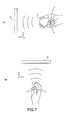
- FIGS. 7 are explanatory diagrams therefor.
- the user holds the input apparatus 1 so as to aim the buttons 11 and 12 side of the input apparatus 1 at the display apparatus 5 side.
- the user holds the input apparatus 1 so that a thumb is located on an upper side and a pinky is located on a lower side as in handshakes.
- the circuit board 25 of the sensor unit 17 (see Fig. 8 ) is close to being in parallel with the screen 3 of the display apparatus 5, and the two axes as detection axes of the sensor unit 17 respectively correspond to the horizontal axis (X axis) (pitch axis) and the vertical axis (Y axis) (yaw axis) on the screen 3.
- the position of the input apparatus 1 as shown in Figs. 7(A) and 7(B) will be referred to as reference position.
- the control apparatus 40 controls display of the pointer 2 so that the pointer 2 moves in the Y-axis direction.
- the control apparatus 40 controls display of the pointer 2 so that the pointer 2 moves in the X-axis direction.
- Fig. 9 is a flowchart showing the operation.
- Power of the input apparatus 1 is turned on.
- the power of the input apparatus 1 is turned on.
- biaxial angular velocity signals are output from the angular velocity sensor unit 15.
- the MPU 19 obtains a first angular velocity value ⁇ ⁇ and a second angular velocity value ⁇ ⁇ from the biaxial angular velocity signals (Step 101).
- biaxial acceleration signals are output from the acceleration sensor unit 16.
- the MPU 19 obtains a first acceleration value a x and a second acceleration value ay from the biaxial acceleration signals (Step 102).
- the signals on the acceleration values are signals corresponding to the position of the input apparatus 1 at a point when the power is turned on (hereinafter, referred to as initial position).
- the initial position may be the reference position shown in Figs. 7 , or may be a stand position as shown in Fig. 11 or 12 .
- the MPU 19 typically carries out Steps 101 and 102 in sync every predetermined clock cycle.
- the acceleration signals are obtained by the acceleration sensor unit after the angular velocity signals are obtained by the angular velocity sensor unit.
- the order is not limited thereto, and the angular velocity signals may be obtained after the acceleration signals are obtained, or the acceleration signals and the angular velocity signals may be obtained in parallel (at the same time) (the same holds true for Fig. 10 below).
- the MPU 19 calculates velocity values (first velocity value V x , second velocity value V y ) by a predetermined operation (Step 103).
- the first velocity value V x is a velocity value in a direction along the X axis
- the second velocity value V y is a velocity value in a direction along the Y axis.
- at least the sensor unit 17 alone or the MPU 19 and the sensor unit 17 functions/function as an input information generation means for generating input information that corresponds to a movement of the casing 10 and is used for moving the pointer 2 on the screen 3.
- the MPU 19 divides the acceleration values (a x , a y ) by angular acceleration values ( ⁇ ⁇ , ⁇ ⁇ ) to thus obtain radius gyrations (R ⁇ , R ⁇ ) of the movement of the input apparatus 1.
- the velocity values (V x , V y ) can be calculated by multiplying the radius gyrations (R ⁇ , R ⁇ ) by the angular velocity values ( ⁇ ⁇ , ⁇ ⁇ ).
- the radius gyrations (R ⁇ , R ⁇ ) may also be obtained by dividing acceleration change rates ( ⁇ a x , ⁇ a y ) by angular acceleration change rates ( ⁇ ( ⁇ ⁇ )' ⁇ ( ⁇ ⁇ )).
- the MPU 19 may calculate the velocity values by, for example, integrating the acceleration values (a x , a y ) while using the angular velocity values ( ⁇ ⁇ , ⁇ ⁇ ) as an adminicle for the integration operation.
- the velocity values (V x , V y ) may be calculated by simply integrating the acceleration values (a x , a y ).
- the detected angular velocity values ( ⁇ ⁇ , ⁇ ⁇ ) may be used as they are as the velocity values (V x , V y ) of the casing. It is also possible to obtain angular acceleration values ( ⁇ ⁇ , ⁇ ⁇ ) by temporally differentiating the detected angular velocity values ( ⁇ ⁇ , ⁇ ⁇ ), and use them as the acceleration values of the casing.
- the MPU 19 transmits, as the input information, information on the calculated velocity values (V x , V y ) to the control apparatus 40 via the transceiver 21 and the antenna 22 (Step 104).
- the MPU 35 of the control apparatus 40 receives the information on the velocity values (V x , V y ) via the antenna 39 and the transceiver 38 (Step 105).
- the input apparatus 1 transmits the velocity values (V x , V y ) every predetermined clocks, that is, per unit time, so the control apparatus 40 can receive this and obtain displacement amounts in the X- and Y-axis directions per unit time.
- the MPU 35 generates coordinate values (X(t), Y(t)) (coordinate information) of the pointer 2 on the screen 3 that correspond to the obtained displacement amounts in the X- and Y-axis directions per unit time by Equations (1) and (2) below (Step 106) (generation means). Based on the generated coordinate values, the MPU 35 controls display so that the pointer 2 moves on the screen 3 (Step 107).
- the input apparatus 1 has calculated the velocity values (V x , V y ) by carrying out main operations.
- the control apparatus 40 carries out the main operations.
- Steps 201 and 202 are the same as those of Steps 101 and 102.
- the input apparatus 1 transmits to the control apparatus 40 information on detection values which are, for example, biaxial acceleration values and biaxial angular velocity values output from the sensor unit 17 (Step 203).
- the MPU 35 of the control apparatus 40 receives the information on the detection values (Step 204) and executes the same processes as Steps 103, 106, and 107 (Step 205 to 207).
- Fig. 11 is a diagram showing an example of a screen displayed on the display apparatus 5, the display of which is controlled by the control apparatus 40.
- the MPU 35 of the control apparatus 40 controls display of a real screen 95 and the pointer 2 on the real screen 95.
- the MPU 35 also controls a movement of the pointer 2 on a virtual screen 105 set around the real screen 95.
- the real screen 95 is a screen that is actually displayed on the display apparatus 5.
- the virtual screen 105 is a virtual screen that is not displayed on the display apparatus 5 and stored by the control apparatus 40.
- the number of pixels of the real screen 95 is Xr x Yr, and the number of pixels of the virtual screen 105 is Xv x Yv.
- (Xr, Yr) may variously be, for example, (1280, 1024), (1920, 1080), and (2048, 1152), but are not limited thereto.
- (Xv, Yv) only need to be larger than (Xr, Yr).
- (Xr, Yr) are (800, 600)
- (Xv, Yv) are, for example, equal to or larger than (or smaller than) (1280, 1024).
- (Xr, Yr) are (1920, 1080)
- (Xv, Yv) are (3920, 3080) or the like.
- a combination of (Xr, Yr) and (Xv, Yv) is not limited.
- the MPU 35 When generating coordinate values of the pointer 2 on the real screen 95, the MPU 35 generates coordinate values using a Cartesian coordinate system on the real screen 95 (first coordinate system). Similarly, when generating coordinate values of the pointer 2 on the virtual screen 105, the MPU 35 generates coordinate values using a Cartesian coordinate system on the virtual screen 105 (second coordinate system). At least coordinates on a boundary line (described later) at an end portion of the real screen 95 between the real screen 95 and the second coordinate system may be set so that the first and second coordinate systems overlap each other.
- the second coordinate system is a coordinate system continuous with the first coordinate system (or relative to the first coordinate system). For example, assuming that coordinate values at four corners on the real screen 95 are (0, 0), (x1, 0), (0, y1), and (x1, y1) and coordinate values at four corners on the virtual screen 105 are (-x2, -y2), (x1+x2, -y2), (-x2, y1+y2), and (x1+x2, y1+y2), the virtual screen 105 becomes larger than the real screen 95 by an amount corresponding to the number of pixels several times larger than x2 in the lateral direction and larger than the real screen 95 by an amount corresponding to the number of pixels several times larger than y2 in the longitudinal direction.
- the MPU 35 stores data of the first and second coordinate systems of the real screen 95 and the virtual screen 105, respectively, in the ROM 37, the RAM 36, or other memories.
- the MPU 35 may alternatively store in the memory the data of both coordinate systems as coordinate systems having at least a partial area of the second coordinate system overlapping the first coordinate system.
- the memory may store the data of the first coordinate system of the real screen 95 and the data of the second coordinate system of the virtual screen 105 including a part (e.g., boundary line at end portion) or all of a coordinate range of the real screen 95.
- a screen including the real screen 95 and the virtual screen 105 will be referred to as entire screen 155.
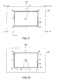
- Fig. 12 is a diagram for illustrating a calibration task for determining, when a user uses the control system 100, a relationship between a spatial position of the input apparatus 1 and a position of the pointer 2 on the entire screen 155.
- the MPU 35 of the control apparatus 40 displays a predetermined figure or mark (hereinafter, referred to as calibration mark) 96 on a part of the real screen 95, for example, at a center position.
- the calibration mark 96 is displayed in a predetermined pixel range (area).
- a display position (reference position) of the calibration mark 96 is not limited to the center position of the real screen 95 and may be, for example, at least one of four corners 97 of the real screen 95.
- the display position of the calibration mark 96 may alternatively be two or more including the center position and at least one of the four corners 97.
- the MPU 35 can calibrate, for example, the number of pixels corresponding to that movement amount with respect to the movement velocity of the input apparatus 1. Specifically, it becomes possible to calibrate how long a distance (number of pixels) the pointer moves when the input apparatus 1 is moved by what velocity (or how long a distance) by the user. As a result, an operational feeling of the user can be additionally improved.
- the user By holding the input apparatus 1 in the reference position as shown in Figs. 7 and moving the casing 10, for example, the user aims the input apparatus 1 at the display position of the calibration mark 96. By the user pressing, for example, the button 11 or other buttons while aiming the input apparatus 1 at the calibration mark 96, a determination command signal is generated from the input apparatus 1.
- the determination command signal is transmitted to the control apparatus 40 to be received by the control apparatus 40.
- the MPU 35 of the control apparatus 40 executes processing for making the position of the pointer 2 correspond to the calibration mark 96 (correction means).
- the pointer 2 is displayed at (or moved to) the display position of the calibration mark 96.
- the MPU 35 stores a signal indicating that the current position of the pointer 2 is the center position of the real screen 95 in the memory. Accordingly, the MPU 35 controls a movement of the pointer 2 assuming that the movement of the input apparatus 1 indicates a pseudo absolute position in space with respect to the real screen 95. In other words, though there is a relative positional relationship between the input apparatus 1 and the entire screen 155, the input apparatus 1 has an absolute positional relationship in space with respect to the real screen 95.
- the MPU 35 may temporarily display the pointer 2 with emphasis when the pointer 2 is displayed on the calibration mark 96. As a result, it is possible to make the user recognize that the display position of the pointer 2 has been corrected.
- the emphasis display of the pointer 2 includes highlight display, enlargement display, and the like of the pointer 2.
- control apparatus 40 obtains device information (screen information, other bibliographic information, etc.) of the display apparatus 5 at a point when it is electrically connected to the display apparatus 5, for example.
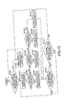
- Fig. 13 is a flowchart thereof.
- the MPU 35 judges whether coordinate values of the pointer 2 generated based on the input information from the input apparatus 1 have reached a boundary line of the first coordinate system (Step 301).
- the boundary line is a line at an end portion of the first coordinate system between the first coordinate system and the second coordinate system, which is, in Fig. 11 , any one of two horizontal lines (+Y and -Y) between the coordinates (0, 0) and (x1, 0) and coordinates (0, y1) and (x1, y1), respectively, and two vertical lines (-X and +X) between the coordinates (0, 0) and (0, y1) and coordinates (x1, 0) and (x1, y1), respectively.
- the boundary line may alternatively be set as a line having a certain amount of width, that is, a line having a width corresponding to two or more pixels.
- Step 301 When the coordinate values of the pointer 2 have not reached the boundary line of the first coordinate system in Step 301, the MPU 35 advances to Step 302. In Step 302, the MPU 35 displays the pointer 2 in accordance with the coordinate values since the pointer 2 is on the first coordinate system.
- the pointer 2 displayed on the real screen 95 may be referred to as real pointer.
- a pointer managed on the virtual screen 105 may be referred to as virtual pointer 2'.
- Step 303 the MPU 35 manages the real pointer 2 and the virtual pointer 2' separately (Step 303).
- the MPU 35 starts generating coordinate values of the virtual pointer 2' in the second coordinate system and manages coordinates of the virtual pointer 2' in the second coordinate system while displaying the real pointer on the boundary line.
- the MPU 35 judges which of the coordinate values respectively belonging to the four boundary lines -Y, -X, +Y, and +X the coordinate values of the pointer 2 are (Steps 304, 306, and 308).
- coordinate values (xa, 0- ⁇ y) of the virtual pointer 2' are stored in the memory. Moreover, in this case, display is made with the coordinate values of the real pointer 2 set to (xa, 0) (Step 305).
- xa is a value that varies.
- Fig. 15 is a diagram showing movements of the virtual pointer 2' and the real pointer 2 at a time when, for example, the coordinate values have crossed over the boundary line -Y from the first coordinate system and entered the second coordinate system (corresponding to Steps 304 and 305).
- a state where the real pointer 2 on the boundary line -Y (x, 0) has moved only by - ⁇ x, - ⁇ y is shown in this case.
- the MPU 35 controls display of the pointer 2 so that the coordinate values of the real pointer 2 move from (x, 0) to (x- ⁇ x, 0).
- the coordinate values (0-5x, ya) of the virtual pointer 2' are stored in the memory. Moreover, in this case, display is made with the coordinate values of the real pointer 2 set to (0, ya) (Step 307).
- ya is a value that varies.
- Fig. 14 is a diagram showing movements of the virtual pointer 2' and the real pointer 2 at a time when, for example, the generated coordinate values have crossed over the boundary line -X from the first coordinate system and entered the second coordinate system (corresponding to Steps 306 and 307).
- a state where the real pointer 2 on the boundary line -X (0, y) has moved only by - ⁇ x, + ⁇ y is shown in this case (a state where a movement is made from coordinate values corresponding to a first input value of the input information from the input apparatus 1 to coordinate values corresponding to a second input value is shown).
- the MPU 35 controls display of the pointer 2 so that the coordinate values of the real pointer 2 move from (0, y) to (0, y+ ⁇ y).
- the coordinate values of the real pointer 2 on the boundary line -X are updated in association with an update of storage of the coordinate values of the virtual pointer 2' on the virtual screen 105.
- the user can recognize where on the virtual screen 105 the pointing is being made in a longitudinal or lateral direction.
- coordinate values (x1+ ⁇ x, ya) of the virtual pointer 2' are stored in the memory. Moreover, in this case, display is made with the coordinate values of the real pointer 2 set to (x1, ya) (Step 310).
- ya is a value that varies.
- the MPU 35 judges whether coordinate values of the pointer that have been generated next have reached the boundary line of the first coordinate system from the second coordinate system (Step 311). When judged NO, the processes from Step 303 are repeated. In subsequent Steps 305, 307, 309, and 310, the coordinate values of the virtual pointer 2' stored in the memory are updated to new coordinate values of the virtual pointer 2'.
- Step 311 the MPU 35 judges whether the coordinate values have reached an area other than the boundary line of the first coordinate system (Step 312) and when judged YES, repeats the processes from Step 302.
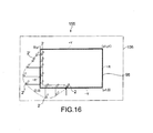
- Fig. 16 is a diagram showing movements of the virtual pointer 2' and the real pointer 2 at a time when, for example, the coordinate values have crossed over the boundary line -X from the first coordinate system and entered the second coordinate system, and have reached an area below the boundary line -Y in the second coordinate system. This state corresponds to Steps 306 to 309 above.
- the coordinates of the virtual pointer 2' are generated not only on the real screen 95 but also on the virtual screen 105 set around the real screen 95 and stored. Accordingly, by moving the input apparatus 1 only by an amount that the input apparatus has moved outside the real screen 95, in an opposite direction, for example, the user can resume the movement of the pointer 2 that has reached the boundary line of the real screen 95, on the real screen 95. As a result, a deviation between the display position of the pointer 2 and a relative position of the input apparatus 1 can be prevented from occurring. In other words, since coordinate values of the pointer are generated in a pseudo absolute coordinate system without being bound by a small screen, the user can operate the input apparatus 1 intuitionally without stress.
- the position of the pointer on the screen is deviated, for example.
- the correction means executing correction processing of the pointer position, the deviation of the display position of the pointer can be eliminated, and an intuitional pointer movement operability for the user can be secured.
- Fig. 17 is a diagram showing a screen that the control apparatus 40 causes the display apparatus 5 to display according to another embodiment.
- the real screen 95 that the control apparatus 40 causes the display apparatus 5 to display includes, at four corners thereof, predetermined icons 98a, 99a, 101a, and 102a.
- Each of the plurality of icons 98a, 99a, 101a, and 102a is image data of a part of a selection operation area (real display area) that is to be a target of a selection operation made by the user using the input apparatus 1.
- the control apparatus 40 stores, in the RAM 36, the ROM 36, or other storage devices, partial selection operation areas (virtual display areas) 98b, 99b, 101b, and 102b that are continuous with the icons 98a, 99a, 101a, and 102a, respectively, in association with the second coordinate system of the virtual screen 105.
- the control apparatus 40 generates image data displayed in the selection operation areas 98, 99, 101, and 102 each including the real display area and the virtual display area.
- the icons 98a, 99a, 101a, and 102a are constantly displayed on the real screen 95, though not limited thereto as will be described later.
- the selection operation area 98 is an operation area for channel-up for television broadcasts and the like.
- the selection operation area 99 is an operation area for channel-down.
- the selection operation area 101 is an operation area for volume-up of audio outputs.
- the selection operation area 102 is an operation area for volume-down of audio outputs.
- the selection operation areas 98, 99, 101, and 102 are set to be rectangular, for example. However, outer shapes thereof may include curved portions, and a setting change can be made to various shapes.
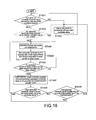
- Fig. 18 is a flowchart showing an operation of the control apparatus 40 according to this embodiment.
- the MPU 35 judges whether the generated coordinate values of the pointer 2 have reached the boundary line of the first coordinate system after the calibration described above (Step 401). When judged NO, the MPU 35 advances to Step 402 as in the processing of Fig. 13 .
- the MPU 35 may alternatively judge whether the coordinate values are within one of the areas of the icons 98a, 99a, 101a, and 102a (Step 403). In this case, the MPU 35 only needs to advance to Step 402 when the coordinate values are not within those areas. The judgment process of Step 403 may be omitted.
- Step 401 the MPU 35 advances to Step 404 and starts generating coordinate values of the virtual pointer 2' in the second coordinate system as in the processing of Fig. 13 .
- Step 405 the MPU 35 executes processing of stopping the real pointer 2 while leaving it on the boundary line or hiding display thereof.
- the MPU 35 next judges whether the generated coordinate values of the virtual pointer 2' are within any one of the selection operation areas 98b, 99b, 101b, and 102b set on the virtual screen 105 (Step 406) (judgment means). When judged NO, the MPU 35 repeats the processes from Step 404.
- Step 406 the MPU 35 controls a selection target in the selection operation area 98b, 99b, 101b, or 102b that corresponds to the generated coordinate values of the virtual pointer 2' (Step 407) (selection control means).
- the MPU 35 only needs to switch channels or select a volume at a predetermined constant velocity, for example. It is also possible to allow the user to customize the constant switching velocity.
- Steps 408 and 409 are the same as those of Steps 311 and 312 shown in Fig. 13 .
- the MPU 35 may execute Step 407 without stopping or hiding display of the real pointer 2, and execute the processes of Steps 305 to 311 shown in Fig. 13 .
- the user can select a selection target through a pointing operation on the virtual screen 105.
- the icons 98a, 99a, 101a, and 102a each exhibit sort of like a function as an index of a selection target.
- Fig. 19 is a modified example of the screen shown in Fig. 17 .
- Selection operations areas 203 to 206 of Fig. 19 are set to be trapezoidal so as to include entire areas of respective sides of the adjacent real screen 95.
- the selection operation area 203 (203a and 203b) is set in both the first and second coordinate systems across the boundary line -X.
- the selection operation area 204 (204a and 204b) is set in both the first and second coordinate systems across the boundary line +X.
- the selection operation area 205 (205a and 205b) is set in both the first and second coordinate systems across the boundary line +Y.
- the selection operation area 206 (206a and 206b) is set in both the first and second coordinate systems across the boundary line -Y.
- the selection operation areas 203 and 204 are operation areas for channel-up and -down, respectively.
- the selection operation areas 205 and 206 are operation areas for volume-up and -down, respectively.
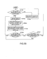
- Fig. 20 is a flowchart showing processing of the control apparatus 40 on the screen shown in Fig. 19 .
- the MPU 35 executing processing obtained by removing Steps 403 and 406 from the flowchart shown in Fig. 18 , the same operational effect as described above can be obtained.
- Fig. 21 is a flowchart showing another processing on the screen shown in Fig. 19 .
- Step 605 is different from Step 505.
- the MPU 35 controls a selection target by variably controlling a switching velocity of a selection target in accordance with coordinate values of the virtual pointer 2' generated based on the input information generated when the user moves the input apparatus 1.
- Step 605 the user can change a speed of selecting a channel (switching velocity) or select a speed of selecting a volume (switching velocity) by moving the input apparatus 1 on the virtual screen 105. Accordingly, the user can intuitionally select a selection target with an analog operational feeling.
- the MPU 35 only needs to variably control the switching velocity in accordance with a distance between the boundary line of the first coordinate system and the virtual pointer 2'.
- the switching velocity only needs to increase (or decrease) as the virtual pointer 2' moves farther away from the boundary line.
- the selection operation area 203b it is only necessary to variably control the channel switching velocity in accordance with a distance from the boundary line -X in the lateral direction.
- the selection operation area is not limited to the configurations of the selection operation areas 98, 99, 101, 102, and 203 to 206 shown in Figs. 17 and 19 .
- a shape, a size, a ratio of a size of one selection operation area on the real screen 95 to a size thereof on the virtual screen 105, and the like can be changed as appropriate.
- the selection operation area may be set only on the virtual screen 105.
- selection targets in the selection operation areas 98, 99, 101, 102, and 203 to 206 are not limited to volume control and channel selection for broadcast programs and the like.
- each of the selection targets is a target to be an item for selection of reproduction/stop of an image, selection of fast-forwarding/rewinding of an image, selection of each of images displayed flowingly on the real screen 95 (so-called scroll function), or various other selection items of a menu screen.
- the MPU 35 may execute variable control of the switching velocity as in Step 505 of Fig. 20 . In this case, even when the virtual pointer 2' has moved out of the selection operation area 98b (or 99b, 101b, or 102b), for example, the MPU 35 may continue the variable control.
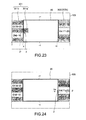
- Figs. 23 and 24 show another embodiment of the present invention.
- the real display areas 98a, 99a, 101a, 102a, 203a, 204a, 205a, and 206a of icons have constantly been displayed on the real screen 95.
- the real display areas of icons are normally not displayed on the real screen 95, and the real display area of an icon is displayed on the real screen 95 when the pointer 2' is moved to the virtual display area of the selection operation area displayed on the virtual screen 105.
- a first selection operation area 301 is set with a virtual display area 301b on the virtual screen 105 along the boundary line -X
- a second selection operation area 302 is set with a virtual display area 302b on the virtual screen 105 along the boundary line +X.
- the first selection operation area 301 is constituted as a channel selection icon for television broadcasts
- the second selection operation area 302 is constituted as a volume (sound volume) adjustment icon.
- the virtual display area 301b of the first selection operation area 301 includes channel setting areas the setting channels of which change stepwise along the boundary line -X
- the virtual display area 302b of the second selection operation area 302 includes volume setting areas the volumes of which change stepwise along the boundary line +X.
- Real display areas 301a and 302a of the first and second selection operation areas 301 and 302, respectively, are not displayed when the pointer 2 is positioned on the real screen 95.
- the real display areas 301a and 302a are displayed when the pointer 2 has crossed over the boundary lines -X and +X and moved to the virtual screen 105.
- Fig. 23 shows a state where the cursor 2 has crossed over the boundary line -X and moved to the virtual screen 105.
- Fig. 24 shows a state where the cursor 2 has crossed over the boundary line +X and moved to the virtual screen 105.
- the MPU 35 judges whether the cursor 2 (2') has crossed over the boundary line -X or +X and moved to the virtual screen 105. Based on the coordinate information of the virtual pointer 2' generated when crossing over the boundary line -X or +X, the MPU 35 determines the corresponding channel setting area or volume setting area. Then, the MPU 35 displays on the real screen 95 an icon indicating a corresponding setting channel or volume (real display areas 301a and 302a). The icons (real display areas 301a and 302a) are displayed adjacent to the setting areas, and icons of different display contents are displayed along the boundary lines -X and +X in accordance with a change in the y coordinate of the pointer 2 (2').
- the channel switch control and volume adjustment control may be executed simultaneous with the display of the icons (real display areas 301a and 302a) on the real screen 95, or may be executed after waiting for a button input operation to be made by the input apparatus 1 with respect to the displayed icons 301a and 302a.
- the channel setting icon (real display area 301a) may be displayed simultaneously with a video received by that channel as a sub screen.
- the sub screen is not limited to an image of the selected channel, and images of a plurality of other channels may be displayed at the same time.
- a group of displayed images may be switched successively along with a vertical movement of the pointer.
- An image selected by an input operation of the pointer 2 is switched to a display image on the real screen 95.
- various display control methods such as a gradual expansion on the real screen 95 starting from the display position of an icon can be adopted.
- Figs. 25 and 26 show a modified example of the screen shown in Figs. 23 and 24 .
- This embodiment shows a screen at a time of video reproduction (editing).
- the real display areas of icons are normally not displayed on the real screen 95, and the real display area of an icon is displayed on the real screen 95 when the pointer 2' is moved to the virtual display area of the selection operation area displayed on the virtual screen 105.
- a first selection operation area 303 is set with a virtual display area 303b on the virtual screen 105 along the boundary line +X
- a second selection operation area 304 is set with a virtual display area 304b on the virtual screen 105 along the boundary line -Y.
- the first selection operation area 303 is constituted as an icon for frame advance of a reproduction screen
- the second selection operation area 304 is constituted as an icon for setting chapters with respect to a video displayed on the real screen 95.
- Real display areas 303a and 304a of the first and second selection operation areas 303 and 304, respectively, are not displayed when the pointer 2 is positioned on the real screen 95.
- the real display areas 303a and 304a are displayed when the pointer 2 has crossed over the boundary lines +X and -Y and moved to the virtual screen 105.
- Fig. 25 shows a state where the cursor 2 has crossed over the boundary line +X and moved to the virtual screen 105.
- Fig. 26 shows a state where the cursor 2 has crossed over the boundary line -Y and moved to the virtual screen 105.
- the MPU 35 judges whether the cursor 2 (2') has crossed over the boundary line +X or -Y and moved to the virtual screen 105. Based on the coordinate information of the virtual pointer 2' generated when crossing over the boundary line +X or -Y, the MPU 35 displays on the real screen 95 an icon displaying a frame advance operation or a chapter setting screen (real display area 303a or 304a). The icons (real display areas 303a and 304a) are displayed adjacent to the setting areas.
- the frame advance control of an image may be executed simultaneous with the display of an icon (real display area 303a) on the real screen 95, or may be executed after waiting for a button input operation to be made on the displayed icon 303a by the input apparatus 1.
- chapter setting control by performing an input operation on the button of the input apparatus 1 when wishing to set a chapter, chapter marks 304d are displayed on a movement path of a seek bar (slider) 304c.
- An embodiment of the present invention is not limited to the above embodiments, and various other embodiments are possible.
- the 3-dimensional operation input apparatus has been exemplified as the input apparatus 1.
- a planar operation input apparatus may be used instead.
- the planar operation input apparatus may be a generally-used mouse, an input apparatus that uses an arrow key used in controllers for games, or an input apparatus such as a joy stick.
- the pointer 2 that moves on the screen in accordance with the movement of the input apparatus 1 has been represented as an image of an arrow.
- the image of the pointer 2 is not limited to the arrow and may be a simple circle, square, or the like, or a character image or any other images.
- the pointer is not limited to that having a finite form like a so-called cursor and includes those of various configurations and with which a UI such as an icon displayed on a screen can be selected.
- the pointer is not limited to that constantly displayed in a finite form and includes that having a configuration in which the position of the pointer becomes explicit when reaching an area in which a UI selection operation can be made.
- display of the pointer 2 may be changed on the boundary line between the real screen 95 and the virtual screen 105 in accordance with a change in the coordinate position of the virtual pointer 2'.
- a display color of the pointer 2 can be changed on the boundary line (boundary line -X in the example shown in the figure) in accordance with the position of the virtual pointer 2'.
- the display color of the pointer changes from white to green when reaching the boundary line.
- the change in the display color includes a change of luminance or concentration of the display color as the virtual pointer 2' moves farther away from the real screen 95, or the like.
- a form of the pointer 2 on the boundary line can be changed in accordance with the position of the virtual pointer 2'.
- the change in the form of the pointer 2 also includes a tilt and a deformation such as squashing of the pointer 2.
- a deformation amount of the pointer 2 can be increased as the virtual pointer 2' moves farther away from the real screen 95. Accordingly, it becomes possible for the user to recognize that the pointer is positioned on the virtual screen and where on the virtual screen the pointer is positioned.
- there is an animation of the pointer 2 such as display of a state where the pointer 2 is running toward the virtual screen.
- the shapes of the real screen 95 and the virtual screen 105 displayed on the display apparatus 5 have been a rectangle.
- the shape of the real screen 95 may be a triangle, a polygon of a pentagon or more, a circle, an oval, or a combination of at least two of the above.
- the virtual screen 105 may be of various shapes. The shapes of the real screen 95 and the virtual screen 105 may differ.
- the coordinate systems of the real screen 95 and the virtual screen 105 have been a Cartesian coordinate system.
- the coordinate system(s) of the real screen and/or the virtual screen may be a polar coordinate system.
- the real screen 95 and the virtual screen 105 have been a plane.
- the real screen and/or the virtual screen may have a curved surface.
- Fig. 13 display control has been performed such that the real pointer 2 moves on the boundary line while the MPU 35 is generating coordinate values of the virtual pointer 2', that is, while the virtual pointer 2' is moving on the virtual screen.
- the MPU 35 it is also possible for the MPU 35 to execute processing uncorrelated to the input information from the input apparatus 1 while generating the coordinate values of the virtual pointer 2'.
- the uncorrelated processing includes processing of hiding display of the pointer, processing of displaying and hiding the pointer (blinking), processing of stopping the pointer on the real screen, processing of changing the pointer to a specific symbol or figure, processing of making the pointer make a specific movement regardless of the input information, and the like.
- the control apparatus 40 has generated the coordinate values of the pointer. However, it is also possible for the input apparatus 1 to generate the coordinate values of the pointer and transmit coordinate information to the control apparatus 40 or transmit a display control signal based on the generated coordinate information to the display apparatus 5.
- the input apparatus 1 includes the acceleration sensor unit 16 but not the angular velocity sensor unit 15.
- the velocity values (V x , V y ) can be obtained in Step 103 by integrating the acceleration values (a x , a y ) detected by the acceleration sensor unit 16 (provided that in this case, angular velocity values ( ⁇ ⁇ , ⁇ ⁇ ) about the Y axis and X axis cannot be obtained). Accelerations may be calculated by an image sensor instead of the acceleration sensor unit 16.
- An angle sensor or an angular acceleration sensor may be used instead of the angular velocity sensor unit 15.
- the angle sensor include a geomagnetic sensor and an image sensor. Change amounts of angle values are detected when using, for example, triaxial geomagnetic sensors. Thus, in this case, the angle values are differentiated to thus obtain angular velocity values.
- the angular acceleration sensor is constituted as a combination of a plurality of acceleration sensors, and the angular velocity values are obtained by integrating angular acceleration values obtained by the angular acceleration sensor.
- the MPU 19 or 35 functions as a calculation means for outputting angle-related values as values related to angles.
- the angular acceleration sensor for detecting angular accelerations about the Y axis and the X axis or a sensor for detecting angles may be used in calculating radius gyrations R(t) as described above.
- the angular velocity values ( ⁇ ⁇ , ⁇ ⁇ ) are obtained by integrating the angular acceleration values detected by the angular acceleration sensor.
- the angular velocity values ( ⁇ ⁇ , ⁇ ⁇ ) are obtained by differentiating the angle values detected by the angle sensor.
- two uniaxial acceleration sensors disposed on the radius gyrations R(t) are typically used. A difference between two acceleration values obtained by the two acceleration sensors is divided by a distance between the two acceleration sensors to thus calculate an angular velocity value of the input apparatus 1 or the like. Similar to the detection principle of the two uniaxial acceleration sensors described above, two biaxial acceleration sensors only need to be used as the biaxial angular acceleration sensor. In this case, in addition to the geomagnetic sensor and the image sensor, the biaxial acceleration sensors only need to be used as the angle sensor so as to realize a principle of obtaining, for example, a roll angle ⁇ (angle about Z axis in Fig. 8 ). Therefore, the two biaxial acceleration sensors only need to be used for detecting biaxial angles about the Y axis and the X axis.
- input information has been transmitted to the control apparatus wirelessly.
- the input information may be transmitted by wire.
- the present invention may be applied to, for example, a handheld-type information processing apparatus (handheld apparatus) including a display section.
- a handheld-type information processing apparatus handheld apparatus
- a pointer displayed on the display section is moved.
- the handheld apparatus include a PDA (Personal Digital Assistance), a cellular phone, a portable music player, and a digital camera.
- each of the angular velocity sensor unit 15 and the acceleration sensor unit 16 of the sensor unit 17 do not necessarily need to be mutually orthogonal like the X' axis and the Y' axis described above.
- the accelerations respectively projected in the mutually-orthogonal axial directions can be obtained by a calculation that uses a trigonometric function.
- the angular velocities about the mutually-orthogonal axes can be obtained by a calculation that uses the trigonometric function.
- the X' and Y' detection axes of the angular velocity sensor unit 15 and the X' and Y' detection axes of the acceleration sensor unit 16 of the sensor unit 17 described in the above embodiments match.
- those detection axes do not necessarily need to match.
- the angular velocity sensor unit 15 and the acceleration sensor unit 16 may be mounted while being deviated a predetermined rotation angle within a main surface of the substrate so that the detection axes of the angular velocity sensor unit 15 and the acceleration sensor unit 16 do not match.
- the accelerations and angular velocities with respect to the respective axes can be obtained by a calculation that uses the trigonometric function.
Landscapes
- Engineering & Computer Science (AREA)
- General Engineering & Computer Science (AREA)
- Theoretical Computer Science (AREA)
- Human Computer Interaction (AREA)
- Physics & Mathematics (AREA)
- General Physics & Mathematics (AREA)
- Computer Networks & Wireless Communication (AREA)
- Position Input By Displaying (AREA)
- User Interface Of Digital Computer (AREA)
- Controls And Circuits For Display Device (AREA)
Abstract
[Object] To provide a control apparatus, an input apparatus, a control system, a control method, and a handheld apparatus that are capable of preventing a deviation between a display position of a pointer and a relative position of the input apparatus when the input apparatus is moved out of a screen from an end portion of the screen, and with which a user can obtain an intuitional operational feeling.
[Solving Means] Not only on a real screen (95) but also on a virtual screen (105) set around the real screen (95), coordinates of a virtual pointer (2') are generated and stored. Accordingly, by moving an input apparatus (1) only by an amount that the input apparatus has moved outside the real screen (95), in an opposite direction, for example, a user can resume a movement of a pointer (2) that has reached a boundary line of the real screen (95), on the real screen (95). As a result, since coordinate values of the pointer are generated in a pseudo absolute coordinate system without being bound by a small screen, the user can operate the input apparatus (1) intuitionally without stress.
Description
- The present invention relates to a control apparatus for controlling display of a pointer on a screen, an input apparatus, a control system, a control method, and a handheld apparatus.
- Pointing devices, particularly a mouse and a touchpad, are used as controllers for GUIs widely used in PCs (Personal Computers). Not just as HIs (Human Interfaces) of PCs as in related art, the GUIs are now starting to be used as an interface for AV equipment and game devices used in living rooms etc. with, for example, televisions as image media. Various pointing devices that a user is capable of operating 3-dimensionally are proposed as controllers for the GUIs of this type (see, for example,
Patent Documents 1 and 2). - For example, there is disclosed a method of controlling a display position on a screen in which, when a mouse cursor is displayed at an end portion of a screen, an image including that mouse cursor is switched to an image including a virtual screen on an outer side of the screen (see, for example, Patent Document 3). Accordingly, an effect that a user can easily find the mouse cursor even when it is at the end portion of the screen can be obtained.
-
- Patent Document 1: Japanese Patent Application Laid-open No.
2001-56743 Fig. 3 ) - Patent Document 2: Japanese Patent No.
3,748,483 Fig. 1 ) - Patent Document 3: Japanese Patent Application Laid-open No.
Hei 10-301753 Fig. 3 ) - In the techniques of
Patent Documents 1 to 3 above, a position of a pointing device and a position on a screen are relative to each other. Therefore, regardless of a position of a hand of a user holding the pointing device, for example, a position of a pointer on a screen is determined. However, in a case where a direction that the pointing device is pointing is deviated from a display position of the pointer, stress may be caused, the tendency of which is considered to be high for people who wish to operate the pointer as if using a laser pointer, for example. - Moreover, there is also a problem that, unless an operation is made while being conscious of a position of the pointer, it is difficult for the user to grasp where the pointer that has moved out of the screen is. Especially when a menu graphic on the screen is displayed at the end portion of the screen, although the pointer is moved to the end portion of the screen and the pointer can be moved no further when the user is pointing a range of that menu graphic, the user tries to continue moving the pointing. Therefore, the display position of the pointer and the relative position of the pointing device are deviated and the user may thus feel awkwardness.
- In view of the circumstances as described above, an object of the present invention is to provide a control apparatus, an input apparatus, a control system, a control method, and a handheld apparatus that are capable of preventing a deviation between a display position of a pointer and a relative position of the input apparatus when the input apparatus is moved out of a screen from an end portion of the screen, and with which a user can obtain an intuitional operational feeling.
- For achieving the object above, according to the present invention, there is provided a control apparatus controlling display of a pointer based on input information corresponding to a movement of an input apparatus, including: a generation means for generating first coordinate information indicating a position of the pointer that corresponds to the input information in a first coordinate system on a real screen displayed, and second coordinate information indicating a position of the pointer that corresponds to the input information in a second coordinate system associated with the first coordinate system on a virtual screen set around the real screen; and a display control means for controlling the display of the pointer on the real screen in accordance with the first coordinate information and the second coordinate information that have been generated.
- In the present invention, not only on the real screen but also on the virtual screen set on an outer side of the real screen, coordinate information (second coordinate information) of the pointer is generated. In other words, coordinate values of the pointer are generated in a pseudo absolute coordinate system without being bound by a small real screen. Accordingly, since it becomes possible to display the pointer again on the real screen from an integration position of movement coordinates on the virtual screen, the user can operate the input apparatus intuitionally without stress.
- The second coordinate system being associated with the first coordinate system refers to a case where the second coordinate system overlaps the first coordinate system, a case where the second coordinate system is continuous with the first coordinate system, and the like.
- Typically, scales of the first and second coordinate systems (scales of coordinates) are substantially the same, but they may be different.
- The input apparatus may be a planar operation input apparatus or a 3-dimensional operation input apparatus to be described later.
- The pointer is not limited to that having a finite form like a so-called cursor and includes those of various configurations with which a UI such as an icon displayed on the screen can be selected. For example, the pointer is not limited to that that is constantly displayed in a finite form and includes a configuration in which the position of the pointer becomes explicit when reaching an area in which a UI selection operation can be made.
- The control apparatus further includes: a storage means for storing a virtual display area on the virtual screen out of a selection operation area as a target of a selection operation by the input apparatus, the virtual display area being stored in association with the second coordinate system; a judgment means for judging whether the generated second coordinate information is within the virtual display area; and a selection control means for controlling the target of the selection operation when the generated second coordinate information is within the virtual display area. Accordingly, by the user performing a pointing operation in the virtual display area of the selection operation area when performing a pointing operation on the virtual screen, a selection target can be selected.
- In the present invention, the entire selection operation area may be the virtual display area. Alternatively, the display control means may generate image data of a real display area on the real screen adjacent to the virtual display area out of the selection operation area. Furthermore, the image data of the real display area may constantly be displayed on a part of the real screen. For example, assuming that, in a state where the pointer is displayed inside the selection operation area on the real screen, the user has performed pointing by operating the input apparatus so that the pointer moves out of the real screen to enter the virtual screen, since the selection operation area (virtual display area) is also set on the virtual screen in association with the second coordinate system in this case, the user can select the selection target by performing a pointing operation on the virtual screen.
- The selection target in the selection operation area is, for example, a target to be a selection item for volume selection (volume control), channel selection for broadcast programs and the like, selection of reproduction/stop of an image, selection of fast-forwarding/rewinding, selection of each of images displayed flowingly on a real screen (so-called scroll function), and various other selection items of a menu screen.
- During control by the selection control means, the pointer may be positioned anywhere on the virtual screen. The control by the selection control means may be continued even when, while the user is performing a selection operation, the position of the pointer moves out of the virtual display area of the selection operation area and enters an area other than the virtual display area on the virtual screen.
- The real display area as the selection operation area on the real screen is not limited to a case where it is constantly displayed on the real screen. Specifically, the display control means may display the real display area on the real screen when the judgment means judges that the second coordinate information is within the virtual display area. Accordingly, it becomes possible to carry out display control of the selection operation area on which an intention of the user is reflected.
- The selection control means variably controls a switching velocity in the selection operation in accordance with a distance between the generated second coordinate information and a boundary line at an end portion of the first coordinate system, the boundary line being a boundary between the first coordinate system and the second coordinate system. Accordingly, a selection operation that matches an intuition of the user becomes possible.
- The switching velocity is, for example, in addition to a volume changing velocity if the selection target is volume and a channel changing velocity if the selection target is a channel, a reproduction velocity, a fast-forwarding velocity, and a scroll velocity.
- The storage means stores the virtual display area of the selection operation area that is provided plurally, the plurality of virtual display areas being stored in association with the second coordinate system. In this case, the display control means may output image data of the virtual display area of each of the plurality of selection operation areas or output only image data of partial virtual display areas corresponding to the display position of the pointer out of the plurality of selection operation areas.
- The display control means controls the display of the pointer so that, when the input information is changed from a first input value that corresponds to a position on a boundary line at an end portion of the first coordinate system, the boundary line being a boundary between the first coordinate system and the second coordinate system, to a second input value that corresponds to a position in an area of the second coordinate system adjacent to the boundary line, the pointer is displayed on the boundary line. In the present invention, when the second coordinate information is generated, the display control means may display the pointer while stopping it on the boundary line or display the pointer while moving it on the boundary line as in the invention to be described later.
- For example, though the boundary line is typically a straight line when viewed macroscopically, it may be a curve instead. The first input value may be a value corresponding to coordinates on the boundary line or a value corresponding to coordinates outside the boundary line on the real screen.
- The display control means controls the display of the pointer so that the pointer moves on the boundary line by updating the first coordinate values on the boundary line in accordance with the second coordinate information generated by the generation means. Accordingly, by checking the position of the pointer displayed on the boundary line on the real screen when performing pointing on the virtual screen using the input apparatus, the user can recognize where on the virtual screen the pointing is being made in a longitudinal or lateral direction.
- The display control means may change a display form of the pointer on the boundary line in accordance with a change in the second input value. Accordingly, it becomes possible for the user to recognize that the pointer is positioned on the virtual screen and where on the virtual screen the pointer is positioned. The change in the display form of the pointer includes a change in a display color of the pointer, a deformation of the pointer, animation, and the like.
- The display control means may generate a signal for executing processing for setting a state of the pointer to be uncorrelated to the input information when the input information is changed from a first input value of the input information that indicates that the pointer is positioned in the first coordinate system to a second input value of the input information that indicates that the pointer is positioned in the second coordinate system.
- The uncorrelated processing is processing of hiding display of the pointer, processing of displaying and hiding the pointer (blinking), processing of stopping the pointer on the real screen, processing of changing the pointer to a specific symbol or figure, processing of making the pointer make a specific movement regardless of the input information, and the like.
- The control apparatus further includes: a judgment means for judging whether the generated first coordinate information is on a boundary line at an end portion of the first coordinate system, the boundary line being a boundary between the first coordinate system and the second coordinate system; and a start means for causing the generation means to start generating the second coordinate information when the first coordinate information is on the boundary line.
- For example, the control apparatus only needs to store coordinate data of the boundary line in advance, and the judgment means only needs to judge whether the generated first coordinate information matches any one of stored coordinate data.
- Alternatively, the control apparatus may cause the generation means to start generating the second coordinate information when the first coordinate information generated as described above is within a second area of the selection operation area though not on the boundary line.
- The control apparatus may further include a reception means for receiving a command signal output in accordance with a button operation of the input apparatus and a correction means for causing the position of the pointer to correspond to a predetermined reference position on the real screen based on the received command signal. For example, in a case where the input apparatus is operated such that a movement operation thereof becomes larger as the pointer comes closer to reaching an area on an outer side of the virtual screen, the position of the pointer on the screen may be deviated. In this case, by the correction means executing correction processing of the pointer position, the deviation of the display position of the pointer can be eliminated, and an intuitional pointer movement operability for the user can be secured.
- The display control means may temporarily display the pointer with emphasis when the pointer is displayed at the reference position. Accordingly, it becomes possible to make the user recognize that the position of the pointer has been corrected. The emphasis display includes highlight display, enlargement display, and the like of a pointer.
- For example, the input apparatus is a 3-dimensional operation input apparatus that generates a velocity value of the input apparatus based on at least one of an acceleration value of the input apparatus and an angular velocity value of the input apparatus and transmits information on the velocity value, and the control apparatus further includes a reception means for receiving the transmitted information on the velocity value as the input information.
- When the velocity value is generated based on the angular velocity value alone, the angular velocity value can be output as the velocity value, for example.
- When the velocity value is generated based on the acceleration value alone, the velocity value only needs to be generated by integrating the acceleration value.
- When the input apparatus includes an angle sensor, an angular velocity value can be obtained by differentiating an angle value obtained by that angle sensor. When the input apparatus includes an angular acceleration sensor, an angular velocity value can be obtained by integrating an angular acceleration value obtained by that angular acceleration sensor.
- The input apparatus is a 3-dimensional operation input apparatus that transmits information on at least one of an acceleration value of the input apparatus and an angular velocity value of the input apparatus, and the control apparatus further includes a reception means and a calculation means. The reception means receives the transmitted information on at least one of the acceleration value and the angular velocity value. The calculation means calculates a velocity value of the input apparatus based on the received information on at least one of the acceleration value and the angular velocity value. In this case, the generation means generates the first coordinate information and the second coordinate information that correspond to the input information while using information on the calculated velocity value as the input information.
- According to the present invention, there is provided an input apparatus controlling display of a pointer, including: a casing; an input information generation means for detecting a movement of the casing and generating input information corresponding to the movement of the casing; a generation means for generating first coordinate information indicating a position of the pointer that corresponds to the input information in a first coordinate system on a real screen displayed, and second coordinate information indicating a position of the pointer that corresponds to the input information in a second coordinate system associated with the first coordinate system on a virtual screen set around the real screen; and a display control means for controlling the display of the pointer on the real screen in accordance with the first coordinate information and the second coordinate information that have been generated.
- According to the present invention, there is provided a control system controlling display of a pointer, including an input apparatus and a control apparatus. The input apparatus includes a casing, an input information generation means for detecting a movement of the casing and generating input information corresponding to the movement of the casing, and a transmission means for transmitting the input information. The control apparatus includes a generation means for generating first coordinate information indicating a position of the pointer that corresponds to the input information in a first coordinate system on a real screen displayed, and second coordinate information indicating a position of the pointer that corresponds to the input information in a second coordinate system associated with the first coordinate system on a virtual screen set around the real screen, and a display control means for controlling the display of the pointer on the real screen in accordance with the first coordinate information and the second coordinate information that have been generated.
- According to the present invention, there is provided a control method controlling display of a pointer based on input information corresponding to a movement of an input apparatus, including: generating first coordinate information indicating a position of the pointer that corresponds to the input information in a first coordinate system on a real screen displayed; controlling the display of the pointer on the real screen in accordance with the first coordinate information and the second coordinate information that have been generated; and generating second coordinate information indicating a position of the pointer that corresponds to the input information in a second coordinate system associated with the first coordinate system on a virtual screen set around the real screen.
- According to the present invention, there is provided a handheld apparatus including: a casing; a display section; an input information generation means for detecting a movement of the casing and generating input information corresponding to the movement of the casing; a generation means for generating first coordinate information indicating a position of the pointer that corresponds to the input information in a first coordinate system on a real screen displayed on the display section, and second coordinate information indicating a position of the pointer that corresponds to the input information in a second coordinate system associated with the first coordinate system on a virtual screen set around the real screen; and a display control means for controlling display of the pointer on the real screen in accordance with the first coordinate information and the second coordinate information that have been generated.
- As described above, according to the present invention, a deviation between a display position of a pointer and a relative position of an input apparatus can be prevented from occurring when the input apparatus is moved out of a screen from an end portion of the screen, and a user can obtain an intuitional operational feeling.
- Hereinafter, embodiments of the present invention will be described with reference to the drawings.
-
Fig. 1 is a diagram showing a control system according to an embodiment of the present invention. Acontrol system 100 includes adisplay apparatus 5, acontrol apparatus 40, and a 3-dimensionaloperation input apparatus 1. -
Fig. 2 is a perspective diagram showing the 3-dimensionaloperation input apparatus 1. In descriptions below, the 3-dimensional operation input apparatus will simply be referred to as input apparatus. Theinput apparatus 1 is of a size that a user is capable of holding. Theinput apparatus 1 includes acasing 10 and operation sections including twobuttons casing 10, arotary wheel button 13, and the like. Thebutton 11 disposed closer to the center of the upper portion of thecasing 10 functions as a left button of a mouse as an input device for a PC, for example, and thebutton 12 adjacent to thebutton 11 functions as a right button of a mouse. - For example, "drag and drop" may be executed by moving the
input apparatus 1 while pressing thebutton 11, a file may be opened by double-clicking thebutton 11, and ascreen 3 may be scrolled by thewheel button 13. Locations of thebuttons wheel button 13, a content of a command issued, and the like can arbitrarily be changed. -
Fig. 3 is a diagram schematically showing an internal structure of theinput apparatus 1.Fig. 4 is a block diagram showing an electrical structure of theinput apparatus 1. - The
input apparatus 1 includes asensor unit 17, acontrol unit 30, andbatteries 14. -
Fig. 8 is a perspective diagram showing thesensor unit 17. Thesensor unit 17 includes anacceleration sensor unit 16 for detecting accelerations in different angles such as along two orthogonal axes (X' axis and Y' axis). Specifically, theacceleration sensor unit 16 includes two sensors, that is, afirst acceleration sensor 161 and asecond acceleration sensor 162. Thesensor unit 17 further includes an angularvelocity sensor unit 15 for detecting angular accelerations about the two orthogonal axes. Specifically, the angularvelocity sensor unit 15 includes two sensors, that is, a firstangular velocity sensor 151 and a secondangular velocity sensor 152. Theacceleration sensor unit 16 and the angularvelocity sensor unit 15 are packaged and mounted on acircuit board 25. - As each of the first and second
angular velocity sensors second acceleration sensors angular velocity sensor - In descriptions on
Figs. 2 and 3 , a longitudinal direction of thecasing 10 is referred to as Z' direction, a thickness direction of thecasing 10 is referred to as X' direction, and a width direction of thecasing 10 is referred to as Y' direction for convenience. In this case, thesensor unit 17 is incorporated into thecasing 10 such that a surface of thecircuit board 25 on which theacceleration sensor unit 16 and the angularvelocity sensor unit 15 are mounted becomes substantially parallel to an X'-Y' plane. As described above, thesensor units input apparatus 1, that is, a coordinate system fixed to theinput apparatus 1 is expressed using the X' axis, Y' axis, and Z' axis, whereas a coordinate system stationary on earth, that is, an inertial coordinate system is expressed using the X axis, Y axis, and Z axis. A plane including an X' axis (pitch axis) and a Y' axis (yaw axis) is an acceleration detection surface, that is, a plane substantially parallel to a main surface of the circuit board 25 (hereinafter, simply referred to as detection surface). Further, in descriptions below, with regard to a movement of theinput apparatus 1, a rotational direction about the X' axis is sometimes referred to as pitch direction, a rotational direction about the Y' axis is sometimes referred to as yaw direction, and a rotational direction about the Z' axis (roll axis) direction is sometimes referred to as roll direction. - The
control unit 30 includes amain substrate 18, an MPU 19 (Micro Processing Unit) (or CPU) mounted on themain substrate 18, acrystal oscillator 20, atransceiver 21, and anantenna 22 printed on themain substrate 18. - The
MPU 19 includes a built-in volatile or nonvolatile memory requisite therefor. TheMPU 19 is input with a detection signal from thesensor unit 17, an operation signal from the operation sections, and the like, and executes various kinds of operational processing in order to generate predetermined control signals in response to those input signals. The memory may be provided separate from theMPU 19. A DSP (Digital Signal Processor), an FPGA (Field Programmable Gate Array), and the like may be used in place of theMPU 19. - Typically, the
sensor unit 17 outputs analog signals. In this case, theMPU 19 includes an A/D (Analog/Digital) converter. Alternatively, thesensor unit 17 may be a unit that includes the A/D converter. - The
transceiver 21 transmits, as RF radio signals, a control signal (input information) generated in theMPU 19 to thecontrol apparatus 40 via theantenna 22. Thetransceiver 21 is also capable of receiving various signals transmitted from thecontrol apparatus 40. - The
crystal oscillator 20 generates clocks and supplies them to theMPU 19. As thebatteries 14, dry cell batteries, rechargeable batteries, and the like are used. - The
control apparatus 40 includes an MPU 35 (or CPU), aRAM 36, aROM 37, avideo RAM 41, adisplay control section 42, anantenna 39, and atransceiver 38. - The
transceiver 38 receives the control signal (input information) transmitted from theinput apparatus 1 via theantenna 39. Thetransceiver 38 is also capable of transmitting various predetermined signals to theinput apparatus 1. TheMPU 35 analyzes the control signal and executes various kinds of operational processing. Thedisplay control section 42 mainly generates screen data to be displayed on thescreen 3 of thedisplay apparatus 5 under control of theMPU 35. Thevideo RAM 41 as a working area of thedisplay control section 42 temporarily stores the generated screen data. - The
control apparatus 40 may be an apparatus dedicated to theinput apparatus 1, or may be a PC or the like. Thecontrol apparatus 40 is not limited to the apparatus dedicated to theinput apparatus 1, and may be a computer integrally formed with thedisplay apparatus 5, audiovisual equipment, a projector, a game device, a car navigation system, or the like. - Examples of the
display apparatus 5 include a liquid crystal display and an EL (Electro-Luminescence) display, but are not limited thereto. Thedisplay apparatus 5 may alternatively be an apparatus integrally formed with a display and capable of receiving television broadcasts and the like, or an apparatus in which such a display and thecontrol apparatus 40 are integrated. -
Fig. 5 is a diagram showing an example of thescreen 3 displayed on thedisplay apparatus 5. UIs such asicons 4 and apointer 2 are displayed on thescreen 3. The icons are images on thescreen 3 representing functions of programs, execution commands, file contents, and the like of the computer. It should be noted that on thescreen 3, the horizontal direction is referred to as X-axis direction and the vertical direction is referred to as Y-axis direction. -
Fig. 6 is a diagram showing a state where a user is holding theinput apparatus 1. As shown inFig. 6 , theinput apparatus 1 may include, in addition to thebuttons input apparatus 1 in the air or operates the operation sections while holding theinput apparatus 1 as shown in the figure, input information thereof is output to thecontrol apparatus 40, and thecontrol apparatus 40 controls the UI. - Next, a description will be given on typical examples of ways of moving the
input apparatus 1 and ways thepointer 2 moves on thescreen 3 accordingly.Figs. 7 are explanatory diagrams therefor. - As shown in
Figs. 7(A) and 7(B) , the user holds theinput apparatus 1 so as to aim thebuttons input apparatus 1 at thedisplay apparatus 5 side. The user holds theinput apparatus 1 so that a thumb is located on an upper side and a pinky is located on a lower side as in handshakes. In this state, thecircuit board 25 of the sensor unit 17 (seeFig. 8 ) is close to being in parallel with thescreen 3 of thedisplay apparatus 5, and the two axes as detection axes of thesensor unit 17 respectively correspond to the horizontal axis (X axis) (pitch axis) and the vertical axis (Y axis) (yaw axis) on thescreen 3. Hereinafter, the position of theinput apparatus 1 as shown inFigs. 7(A) and 7(B) will be referred to as reference position. - As shown in
Fig. 7(A) , in the reference position, the user swings a wrist or an arm in the vertical direction, that is, the pitch direction. At this time, thesecond acceleration sensor 162 detects an acceleration (second acceleration) in the Y-axis direction, and the firstangular velocity sensor 151 detects an angular velocity (first angular velocity) ωψ about the Y axis as an angle-related value. Based on those detection values, thecontrol apparatus 40 controls display of thepointer 2 so that thepointer 2 moves in the Y-axis direction. - Meanwhile, as shown in
Fig. 7(B) , in the reference position, the user swings the wrist or the arm in the lateral direction, that is, the yaw direction. At this time, thefirst acceleration sensor 161 detects an acceleration (first acceleration) in the X-axis direction, and the secondangular velocity sensor 152 detects an angular-velocity (second angular velocity) ωθ about the X axis as the angle-related value. Based on those detection values, thecontrol apparatus 40 controls display of thepointer 2 so that thepointer 2 moves in the X-axis direction. - Next, a basic operation of the
control system 100 structured as described above will be described.Fig. 9 is a flowchart showing the operation. - Power of the
input apparatus 1 is turned on. By the user turning on the power supply switch or the like provided to theinput apparatus 1 or thecontrol apparatus 40, for example, the power of theinput apparatus 1 is turned on. When the power is turned on, biaxial angular velocity signals are output from the angularvelocity sensor unit 15. TheMPU 19 obtains a first angular velocity value ωψ and a second angular velocity value ωθ from the biaxial angular velocity signals (Step 101). - Further, upon turning on the power of the
input apparatus 1, biaxial acceleration signals are output from theacceleration sensor unit 16. TheMPU 19 obtains a first acceleration value ax and a second acceleration value ay from the biaxial acceleration signals (Step 102). The signals on the acceleration values are signals corresponding to the position of theinput apparatus 1 at a point when the power is turned on (hereinafter, referred to as initial position). The initial position may be the reference position shown inFigs. 7 , or may be a stand position as shown inFig. 11 or 12 . - It should be noted that the
MPU 19 typically carries outSteps - It should be noted that in
Fig. 9 and the like, the acceleration signals are obtained by the acceleration sensor unit after the angular velocity signals are obtained by the angular velocity sensor unit. However, the order is not limited thereto, and the angular velocity signals may be obtained after the acceleration signals are obtained, or the acceleration signals and the angular velocity signals may be obtained in parallel (at the same time) (the same holds true forFig. 10 below). - Based on the acceleration values (ax, ay) and the angular velocity values (ωψ, ωθ), the
MPU 19 calculates velocity values (first velocity value Vx, second velocity value Vy) by a predetermined operation (Step 103). The first velocity value Vx is a velocity value in a direction along the X axis and the second velocity value Vy is a velocity value in a direction along the Y axis. In this point, at least thesensor unit 17 alone or theMPU 19 and thesensor unit 17 functions/function as an input information generation means for generating input information that corresponds to a movement of thecasing 10 and is used for moving thepointer 2 on thescreen 3. - As a method of calculating velocity values (Vx, Vy), in this embodiment, the
MPU 19 divides the acceleration values (ax, ay) by angular acceleration values (Δωψ, Δωθ) to thus obtain radius gyrations (Rψ, Rθ) of the movement of theinput apparatus 1. In this case, the velocity values (Vx, Vy) can be calculated by multiplying the radius gyrations (Rψ, Rθ) by the angular velocity values (ωψ, ωθ). The radius gyrations (Rψ, Rθ) may also be obtained by dividing acceleration change rates (Δax, Δay) by angular acceleration change rates (Δ(Δωψ)' Δ(Δωθ)).
By calculating the velocity values by the calculation method described above, an operational feeling of theinput apparatus 1 that matches an intuition of the user can be obtained, and moreover, the movement of thepointer 2 on thescreen 3 also accurately matches the movement of theinput apparatus 1.
It should be noted that the velocity values (Vx, Vy) do not always need to be calculated by the calculation method above. For example, theMPU 19 may calculate the velocity values by, for example, integrating the acceleration values (ax, ay) while using the angular velocity values (ωψ, ωθ) as an adminicle for the integration operation. Alternatively, it is also possible for the velocity values (Vx, Vy) to be calculated by simply integrating the acceleration values (ax, ay). Alternatively, the detected angular velocity values (ωψ, ωθ) may be used as they are as the velocity values (Vx, Vy) of the casing. It is also possible to obtain angular acceleration values (Δωψ, Δωθ) by temporally differentiating the detected angular velocity values (ωψ, ωθ), and use them as the acceleration values of the casing. - The
MPU 19 transmits, as the input information, information on the calculated velocity values (Vx, Vy) to thecontrol apparatus 40 via thetransceiver 21 and the antenna 22 (Step 104). - The
MPU 35 of thecontrol apparatus 40 receives the information on the velocity values (Vx, Vy) via theantenna 39 and the transceiver 38 (Step 105). Theinput apparatus 1 transmits the velocity values (Vx, Vy) every predetermined clocks, that is, per unit time, so thecontrol apparatus 40 can receive this and obtain displacement amounts in the X- and Y-axis directions per unit time. - The
MPU 35 generates coordinate values (X(t), Y(t)) (coordinate information) of thepointer 2 on thescreen 3 that correspond to the obtained displacement amounts in the X- and Y-axis directions per unit time by Equations (1) and (2) below (Step 106) (generation means). Based on the generated coordinate values, theMPU 35 controls display so that thepointer 2 moves on the screen 3 (Step 107). -


- In
Fig. 9 , theinput apparatus 1 has calculated the velocity values (Vx, Vy) by carrying out main operations. In an embodiment shown inFig. 10 , thecontrol apparatus 40 carries out the main operations. - As shown in
Fig. 10 , processes of Steps 201 and 202 are the same as those ofSteps input apparatus 1 transmits to thecontrol apparatus 40 information on detection values which are, for example, biaxial acceleration values and biaxial angular velocity values output from the sensor unit 17 (Step 203). TheMPU 35 of thecontrol apparatus 40 receives the information on the detection values (Step 204) and executes the same processes as Steps 103, 106, and 107 (Step 205 to 207). - Next, a main portion of the embodiment of the present invention will be described.
-
Fig. 11 is a diagram showing an example of a screen displayed on thedisplay apparatus 5, the display of which is controlled by thecontrol apparatus 40. - The
MPU 35 of thecontrol apparatus 40 controls display of areal screen 95 and thepointer 2 on thereal screen 95. TheMPU 35 also controls a movement of thepointer 2 on avirtual screen 105 set around thereal screen 95. - The
real screen 95 is a screen that is actually displayed on thedisplay apparatus 5. Thevirtual screen 105 is a virtual screen that is not displayed on thedisplay apparatus 5 and stored by thecontrol apparatus 40. The number of pixels of thereal screen 95 is Xr x Yr, and the number of pixels of thevirtual screen 105 is Xv x Yv. - (Xr, Yr) may variously be, for example, (1280, 1024), (1920, 1080), and (2048, 1152), but are not limited thereto.
- (Xv, Yv) only need to be larger than (Xr, Yr). For example, when (Xr, Yr) are (800, 600), (Xv, Yv) are, for example, equal to or larger than (or smaller than) (1280, 1024). Alternatively, when (Xr, Yr) are (1920, 1080), (Xv, Yv) are (3920, 3080) or the like. However, a combination of (Xr, Yr) and (Xv, Yv) is not limited.
- When generating coordinate values of the
pointer 2 on thereal screen 95, theMPU 35 generates coordinate values using a Cartesian coordinate system on the real screen 95 (first coordinate system). Similarly, when generating coordinate values of thepointer 2 on thevirtual screen 105, theMPU 35 generates coordinate values using a Cartesian coordinate system on the virtual screen 105 (second coordinate system). At least coordinates on a boundary line (described later) at an end portion of thereal screen 95 between thereal screen 95 and the second coordinate system may be set so that the first and second coordinate systems overlap each other. - The second coordinate system is a coordinate system continuous with the first coordinate system (or relative to the first coordinate system). For example, assuming that coordinate values at four corners on the
real screen 95 are (0, 0), (x1, 0), (0, y1), and (x1, y1) and coordinate values at four corners on thevirtual screen 105 are (-x2, -y2), (x1+x2, -y2), (-x2, y1+y2), and (x1+x2, y1+y2), thevirtual screen 105 becomes larger than thereal screen 95 by an amount corresponding to the number of pixels several times larger than x2 in the lateral direction and larger than thereal screen 95 by an amount corresponding to the number of pixels several times larger than y2 in the longitudinal direction. TheMPU 35 stores data of the first and second coordinate systems of thereal screen 95 and thevirtual screen 105, respectively, in theROM 37, theRAM 36, or other memories. - The
MPU 35 may alternatively store in the memory the data of both coordinate systems as coordinate systems having at least a partial area of the second coordinate system overlapping the first coordinate system. In other words, the memory may store the data of the first coordinate system of thereal screen 95 and the data of the second coordinate system of thevirtual screen 105 including a part (e.g., boundary line at end portion) or all of a coordinate range of thereal screen 95. - It should be noted that hereinafter, a screen including the
real screen 95 and thevirtual screen 105 will be referred to asentire screen 155. -
Fig. 12 is a diagram for illustrating a calibration task for determining, when a user uses thecontrol system 100, a relationship between a spatial position of theinput apparatus 1 and a position of thepointer 2 on theentire screen 155. - For example, the
MPU 35 of thecontrol apparatus 40 displays a predetermined figure or mark (hereinafter, referred to as calibration mark) 96 on a part of thereal screen 95, for example, at a center position. Thecalibration mark 96 is displayed in a predetermined pixel range (area). A display position (reference position) of thecalibration mark 96 is not limited to the center position of thereal screen 95 and may be, for example, at least one of fourcorners 97 of thereal screen 95. The display position of thecalibration mark 96 may alternatively be two or more including the center position and at least one of the fourcorners 97. - For example, by a calibration that uses at least two calibration marks 96, the following effect can be obtained. By comparing the number of pixels between the two points and a movement velocity of the pointer (or integration value thereof) between the two points, the
MPU 35 can calibrate, for example, the number of pixels corresponding to that movement amount with respect to the movement velocity of theinput apparatus 1. Specifically, it becomes possible to calibrate how long a distance (number of pixels) the pointer moves when theinput apparatus 1 is moved by what velocity (or how long a distance) by the user. As a result, an operational feeling of the user can be additionally improved. - By holding the
input apparatus 1 in the reference position as shown inFigs. 7 and moving thecasing 10, for example, the user aims theinput apparatus 1 at the display position of thecalibration mark 96. By the user pressing, for example, thebutton 11 or other buttons while aiming theinput apparatus 1 at thecalibration mark 96, a determination command signal is generated from theinput apparatus 1. - The determination command signal is transmitted to the
control apparatus 40 to be received by thecontrol apparatus 40. Upon receiving the determination command signal in a state where theinput apparatus 1 is aimed at thecalibration mark 96, theMPU 35 of thecontrol apparatus 40 executes processing for making the position of thepointer 2 correspond to the calibration mark 96 (correction means). As a result, thepointer 2 is displayed at (or moved to) the display position of thecalibration mark 96. TheMPU 35 stores a signal indicating that the current position of thepointer 2 is the center position of thereal screen 95 in the memory. Accordingly, theMPU 35 controls a movement of thepointer 2 assuming that the movement of theinput apparatus 1 indicates a pseudo absolute position in space with respect to thereal screen 95. In other words, though there is a relative positional relationship between theinput apparatus 1 and theentire screen 155, theinput apparatus 1 has an absolute positional relationship in space with respect to thereal screen 95. - It should be noted that, by the same method as described above, it is also possible to correct, by displaying the calibration mark at any or all of the four corners of the
real screen 95, the display position of thepointer 2 at that(those) position(s). - The
MPU 35 may temporarily display thepointer 2 with emphasis when thepointer 2 is displayed on thecalibration mark 96. As a result, it is possible to make the user recognize that the display position of thepointer 2 has been corrected. The emphasis display of thepointer 2 includes highlight display, enlargement display, and the like of thepointer 2. - It should be noted that the
control apparatus 40 obtains device information (screen information, other bibliographic information, etc.) of thedisplay apparatus 5 at a point when it is electrically connected to thedisplay apparatus 5, for example. - Next, an operation carried out at a time when the
control apparatus 40 controls the movement of thepointer 2 using thereal screen 95 and thevirtual screen 105 as described above will be described.Fig. 13 is a flowchart thereof. - Upon ending the calibration as described above, the
MPU 35 judges whether coordinate values of thepointer 2 generated based on the input information from theinput apparatus 1 have reached a boundary line of the first coordinate system (Step 301). - The boundary line is a line at an end portion of the first coordinate system between the first coordinate system and the second coordinate system, which is, in
Fig. 11 , any one of two horizontal lines (+Y and -Y) between the coordinates (0, 0) and (x1, 0) and coordinates (0, y1) and (x1, y1), respectively, and two vertical lines (-X and +X) between the coordinates (0, 0) and (0, y1) and coordinates (x1, 0) and (x1, y1), respectively. - The boundary line may alternatively be set as a line having a certain amount of width, that is, a line having a width corresponding to two or more pixels.
- When the coordinate values of the
pointer 2 have not reached the boundary line of the first coordinate system inStep 301, theMPU 35 advances to Step 302. InStep 302, theMPU 35 displays thepointer 2 in accordance with the coordinate values since thepointer 2 is on the first coordinate system. - To help understand descriptions below, the
pointer 2 displayed on thereal screen 95 may be referred to as real pointer. In addition, a pointer managed on thevirtual screen 105 may be referred to asvirtual pointer 2'. - When the coordinate values of the
pointer 2 have reached the boundary line of the first coordinate system inStep 301, theMPU 35 manages thereal pointer 2 and thevirtual pointer 2' separately (Step 303). In this embodiment, inStep 303, theMPU 35 starts generating coordinate values of thevirtual pointer 2' in the second coordinate system and manages coordinates of thevirtual pointer 2' in the second coordinate system while displaying the real pointer on the boundary line. - The
MPU 35 judges which of the coordinate values respectively belonging to the four boundary lines -Y, -X, +Y, and +X the coordinate values of thepointer 2 are (Steps 304, 306, and 308). - When the coordinate values belong to the boundary line -Y, coordinate values (xa, 0-δy) of the
virtual pointer 2' are stored in the memory. Moreover, in this case, display is made with the coordinate values of thereal pointer 2 set to (xa, 0) (Step 305). Here, xa is a value that varies. -
Fig. 15 is a diagram showing movements of thevirtual pointer 2' and thereal pointer 2 at a time when, for example, the coordinate values have crossed over the boundary line -Y from the first coordinate system and entered the second coordinate system (corresponding toSteps 304 and 305). A state where thereal pointer 2 on the boundary line -Y (x, 0) has moved only by -δx, -δy is shown in this case. Also in this case, theMPU 35 controls display of thepointer 2 so that the coordinate values of thereal pointer 2 move from (x, 0) to (x-δx, 0). - When the coordinate values belong to the boundary line -X, the coordinate values (0-5x, ya) of the
virtual pointer 2' are stored in the memory. Moreover, in this case, display is made with the coordinate values of thereal pointer 2 set to (0, ya) (Step 307). Here, ya is a value that varies. -
Fig. 14 is a diagram showing movements of thevirtual pointer 2' and thereal pointer 2 at a time when, for example, the generated coordinate values have crossed over the boundary line -X from the first coordinate system and entered the second coordinate system (corresponding to Steps 306 and 307). A state where thereal pointer 2 on the boundary line -X (0, y) has moved only by -δx, +δy is shown in this case (a state where a movement is made from coordinate values corresponding to a first input value of the input information from theinput apparatus 1 to coordinate values corresponding to a second input value is shown). In this case, theMPU 35 controls display of thepointer 2 so that the coordinate values of thereal pointer 2 move from (0, y) to (0, y+δy). In other words, the coordinate values of thereal pointer 2 on the boundary line -X are updated in association with an update of storage of the coordinate values of thevirtual pointer 2' on thevirtual screen 105. - Accordingly, by checking the position of the
pointer 2 displayed on the boundary line on thereal screen 95 when performing pointing on thevirtual screen 105, the user can recognize where on thevirtual screen 105 the pointing is being made in a longitudinal or lateral direction. - Referring back to
Fig. 13 , when the coordinate values belong to the boundary line +Y in Step 308, coordinate values (xa, y1+δy) of thevirtual pointer 2' are stored in the memory. Moreover, in this case, display is made with the coordinate values of thereal pointer 2 set to (xa, y1). Here, xa is a value that varies. - When the coordinate values belong to the boundary line +X, coordinate values (x1+δx, ya) of the
virtual pointer 2' are stored in the memory. Moreover, in this case, display is made with the coordinate values of thereal pointer 2 set to (x1, ya) (Step 310). Here, ya is a value that varies. - The
MPU 35 judges whether coordinate values of the pointer that have been generated next have reached the boundary line of the first coordinate system from the second coordinate system (Step 311). When judged NO, the processes fromStep 303 are repeated. In subsequent Steps 305, 307, 309, and 310, the coordinate values of thevirtual pointer 2' stored in the memory are updated to new coordinate values of thevirtual pointer 2'. - When judged YES in Step 311, the
MPU 35 judges whether the coordinate values have reached an area other than the boundary line of the first coordinate system (Step 312) and when judged YES, repeats the processes fromStep 302. -
Fig. 16 is a diagram showing movements of thevirtual pointer 2' and thereal pointer 2 at a time when, for example, the coordinate values have crossed over the boundary line -X from the first coordinate system and entered the second coordinate system, and have reached an area below the boundary line -Y in the second coordinate system. This state corresponds to Steps 306 to 309 above. - As described above, the coordinates of the
virtual pointer 2' are generated not only on thereal screen 95 but also on thevirtual screen 105 set around thereal screen 95 and stored. Accordingly, by moving theinput apparatus 1 only by an amount that the input apparatus has moved outside thereal screen 95, in an opposite direction, for example, the user can resume the movement of thepointer 2 that has reached the boundary line of thereal screen 95, on thereal screen 95. As a result, a deviation between the display position of thepointer 2 and a relative position of theinput apparatus 1 can be prevented from occurring. In other words, since coordinate values of the pointer are generated in a pseudo absolute coordinate system without being bound by a small screen, the user can operate theinput apparatus 1 intuitionally without stress. - Moreover, in a case where the input apparatus is operated such that a movement operation thereof becomes larger as the pointer comes closer to reaching an area on an outer side of the virtual screen, the position of the pointer on the screen is deviated, for example. In this case, by the correction means executing correction processing of the pointer position, the deviation of the display position of the pointer can be eliminated, and an intuitional pointer movement operability for the user can be secured.
- Next, another embodiment of the present invention will be described.
Fig. 17 is a diagram showing a screen that thecontrol apparatus 40 causes thedisplay apparatus 5 to display according to another embodiment. - The
real screen 95 that thecontrol apparatus 40 causes thedisplay apparatus 5 to display includes, at four corners thereof,predetermined icons icons input apparatus 1. - The
control apparatus 40 stores, in theRAM 36, theROM 36, or other storage devices, partial selection operation areas (virtual display areas) 98b, 99b, 101b, and 102b that are continuous with theicons virtual screen 105. Thecontrol apparatus 40 generates image data displayed in theselection operation areas icons real screen 95, though not limited thereto as will be described later. - The
selection operation area 98 is an operation area for channel-up for television broadcasts and the like. Theselection operation area 99 is an operation area for channel-down. Theselection operation area 101 is an operation area for volume-up of audio outputs. Theselection operation area 102 is an operation area for volume-down of audio outputs. Theselection operation areas -
Fig. 18 is a flowchart showing an operation of thecontrol apparatus 40 according to this embodiment. - The
MPU 35 judges whether the generated coordinate values of thepointer 2 have reached the boundary line of the first coordinate system after the calibration described above (Step 401). When judged NO, theMPU 35 advances to Step 402 as in the processing ofFig. 13 . - Here, the
MPU 35 may alternatively judge whether the coordinate values are within one of the areas of theicons MPU 35 only needs to advance to Step 402 when the coordinate values are not within those areas. The judgment process of Step 403 may be omitted. - When judged YES in Step 401, the
MPU 35 advances to Step 404 and starts generating coordinate values of thevirtual pointer 2' in the second coordinate system as in the processing ofFig. 13 . In Step 405, theMPU 35 executes processing of stopping thereal pointer 2 while leaving it on the boundary line or hiding display thereof. - The
MPU 35 next judges whether the generated coordinate values of thevirtual pointer 2' are within any one of theselection operation areas MPU 35 repeats the processes from Step 404. - When judged YES in Step 406, the
MPU 35 controls a selection target in theselection operation area virtual pointer 2' (Step 407) (selection control means). In Step 407, theMPU 35 only needs to switch channels or select a volume at a predetermined constant velocity, for example. It is also possible to allow the user to customize the constant switching velocity. - Processes of Steps 408 and 409 are the same as those of Steps 311 and 312 shown in
Fig. 13 . - It should be noted that in the processes of Step 405 and subsequent steps, the
MPU 35 may execute Step 407 without stopping or hiding display of thereal pointer 2, and execute the processes of Steps 305 to 311 shown inFig. 13 . - In this embodiment, by placing the
pointer 2 on theicon real screen 95, the user can select a selection target through a pointing operation on thevirtual screen 105. In the case of this embodiment, theicons -
Fig. 19 is a modified example of the screen shown inFig. 17 . - In the configuration shown in
Fig. 17 , the shapes of theselection operation areas real screen 95.Selection operations areas 203 to 206 ofFig. 19 are set to be trapezoidal so as to include entire areas of respective sides of the adjacentreal screen 95. The selection operation area 203 (203a and 203b) is set in both the first and second coordinate systems across the boundary line -X. The selection operation area 204 (204a and 204b) is set in both the first and second coordinate systems across the boundary line +X. The selection operation area 205 (205a and 205b) is set in both the first and second coordinate systems across the boundary line +Y. The selection operation area 206 (206a and 206b) is set in both the first and second coordinate systems across the boundary line -Y. - The
selection operation areas selection operation areas -
Fig. 20 is a flowchart showing processing of thecontrol apparatus 40 on the screen shown inFig. 19 . In this embodiment, by theMPU 35 executing processing obtained by removing Steps 403 and 406 from the flowchart shown inFig. 18 , the same operational effect as described above can be obtained. -
Fig. 21 is a flowchart showing another processing on the screen shown inFig. 19 . In this processing flow, Step 605 is different from Step 505. In Step 505, theMPU 35 controls a selection target by variably controlling a switching velocity of a selection target in accordance with coordinate values of thevirtual pointer 2' generated based on the input information generated when the user moves theinput apparatus 1. - Typically, in Step 605, the user can change a speed of selecting a channel (switching velocity) or select a speed of selecting a volume (switching velocity) by moving the
input apparatus 1 on thevirtual screen 105. Accordingly, the user can intuitionally select a selection target with an analog operational feeling. - Referring to
Fig. 22 , typically, theMPU 35 only needs to variably control the switching velocity in accordance with a distance between the boundary line of the first coordinate system and thevirtual pointer 2'. For example, the switching velocity only needs to increase (or decrease) as thevirtual pointer 2' moves farther away from the boundary line. For example, regarding theselection operation area 203b, it is only necessary to variably control the channel switching velocity in accordance with a distance from the boundary line -X in the lateral direction. - The selection operation area is not limited to the configurations of the
selection operation areas Figs. 17 and19 . For example, a shape, a size, a ratio of a size of one selection operation area on thereal screen 95 to a size thereof on thevirtual screen 105, and the like can be changed as appropriate. Alternatively, the selection operation area may be set only on thevirtual screen 105. - Alternatively, selection targets in the
selection operation areas - Also in the processing of the
control apparatus 40 regarding the screen shown inFig. 17 , theMPU 35 may execute variable control of the switching velocity as in Step 505 ofFig. 20 . In this case, even when thevirtual pointer 2' has moved out of theselection operation area 98b (or 99b, 101b, or 102b), for example, theMPU 35 may continue the variable control. -
Figs. 23 and 24 show another embodiment of the present invention. In the embodiments shown inFigs. 17 ,19 , and22 , thereal display areas real screen 95. In this embodiment, the real display areas of icons are normally not displayed on thereal screen 95, and the real display area of an icon is displayed on thereal screen 95 when thepointer 2' is moved to the virtual display area of the selection operation area displayed on thevirtual screen 105. - Referring to
Fig. 23 , for example, a firstselection operation area 301 is set with avirtual display area 301b on thevirtual screen 105 along the boundary line -X, and a secondselection operation area 302 is set with avirtual display area 302b on thevirtual screen 105 along the boundary line +X. - In this embodiment, the first
selection operation area 301 is constituted as a channel selection icon for television broadcasts, and the secondselection operation area 302 is constituted as a volume (sound volume) adjustment icon. Thevirtual display area 301b of the firstselection operation area 301 includes channel setting areas the setting channels of which change stepwise along the boundary line -X, and thevirtual display area 302b of the secondselection operation area 302 includes volume setting areas the volumes of which change stepwise along the boundary line +X. -
Real display areas 301a and 302a of the first and secondselection operation areas pointer 2 is positioned on thereal screen 95. Thereal display areas 301a and 302a are displayed when thepointer 2 has crossed over the boundary lines -X and +X and moved to thevirtual screen 105.Fig. 23 shows a state where thecursor 2 has crossed over the boundary line -X and moved to thevirtual screen 105.Fig. 24 shows a state where thecursor 2 has crossed over the boundary line +X and moved to thevirtual screen 105. - Based on the coordinate information of the cursor 2 (2'), the
MPU 35 judges whether the cursor 2 (2') has crossed over the boundary line -X or +X and moved to thevirtual screen 105. Based on the coordinate information of thevirtual pointer 2' generated when crossing over the boundary line -X or +X, theMPU 35 determines the corresponding channel setting area or volume setting area. Then, theMPU 35 displays on thereal screen 95 an icon indicating a corresponding setting channel or volume (real display areas 301a and 302a). The icons (real display areas 301a and 302a) are displayed adjacent to the setting areas, and icons of different display contents are displayed along the boundary lines -X and +X in accordance with a change in the y coordinate of the pointer 2 (2'). - As described above, by displaying the
real display areas 301a and 302a of theselection operation areas cursor 2 is moved to thevirtual screen 105, it becomes possible to carry out display control of the selection operation areas on which an intention of a user is reflected. Moreover, since theselection operation areas real screen 95, visibility of an image displayed on thereal screen 95 can be improved. - The channel switch control and volume adjustment control may be executed simultaneous with the display of the icons (
real display areas 301a and 302a) on thereal screen 95, or may be executed after waiting for a button input operation to be made by theinput apparatus 1 with respect to the displayedicons 301a and 302a. Moreover, the channel setting icon (real display area 301a) may be displayed simultaneously with a video received by that channel as a sub screen. The sub screen is not limited to an image of the selected channel, and images of a plurality of other channels may be displayed at the same time. In this case, a group of displayed images may be switched successively along with a vertical movement of the pointer. An image selected by an input operation of thepointer 2 is switched to a display image on thereal screen 95. In this case, various display control methods such as a gradual expansion on thereal screen 95 starting from the display position of an icon can be adopted. -
Figs. 25 and 26 show a modified example of the screen shown inFigs. 23 and 24 . This embodiment shows a screen at a time of video reproduction (editing). - Also in this embodiment, the real display areas of icons are normally not displayed on the
real screen 95, and the real display area of an icon is displayed on thereal screen 95 when thepointer 2' is moved to the virtual display area of the selection operation area displayed on thevirtual screen 105. - Referring to
Fig. 25 , for example, a firstselection operation area 303 is set with avirtual display area 303b on thevirtual screen 105 along the boundary line +X, and a secondselection operation area 304 is set with avirtual display area 304b on thevirtual screen 105 along the boundary line -Y. In this embodiment, the firstselection operation area 303 is constituted as an icon for frame advance of a reproduction screen, and the secondselection operation area 304 is constituted as an icon for setting chapters with respect to a video displayed on thereal screen 95. -
Real display areas selection operation areas pointer 2 is positioned on thereal screen 95. Thereal display areas pointer 2 has crossed over the boundary lines +X and -Y and moved to thevirtual screen 105.Fig. 25 shows a state where thecursor 2 has crossed over the boundary line +X and moved to thevirtual screen 105.Fig. 26 shows a state where thecursor 2 has crossed over the boundary line -Y and moved to thevirtual screen 105. - Based on the coordinate information of the cursor 2 (2'), the
MPU 35 judges whether the cursor 2 (2') has crossed over the boundary line +X or -Y and moved to thevirtual screen 105. Based on the coordinate information of thevirtual pointer 2' generated when crossing over the boundary line +X or -Y, theMPU 35 displays on thereal screen 95 an icon displaying a frame advance operation or a chapter setting screen (real display area real display areas - As described above, by displaying the
real display areas selection operation areas real screen 95 only when thecursor 2 is moved to thevirtual screen 105, it becomes possible to carry out display control of the selection operation areas on which an intention of a user is reflected. Moreover, since theselection operation areas real screen 95, visibility of an image displayed on thereal screen 95 can be improved. - The frame advance control of an image may be executed simultaneous with the display of an icon (
real display area 303a) on thereal screen 95, or may be executed after waiting for a button input operation to be made on the displayedicon 303a by theinput apparatus 1. Moreover, in the chapter setting control, by performing an input operation on the button of theinput apparatus 1 when wishing to set a chapter, chapter marks 304d are displayed on a movement path of a seek bar (slider) 304c. - An embodiment of the present invention is not limited to the above embodiments, and various other embodiments are possible.
- In the above embodiments, the 3-dimensional operation input apparatus has been exemplified as the
input apparatus 1. However, a planar operation input apparatus may be used instead. The planar operation input apparatus may be a generally-used mouse, an input apparatus that uses an arrow key used in controllers for games, or an input apparatus such as a joy stick. - In the above embodiments, the
pointer 2 that moves on the screen in accordance with the movement of theinput apparatus 1 has been represented as an image of an arrow. However, the image of thepointer 2 is not limited to the arrow and may be a simple circle, square, or the like, or a character image or any other images. - The pointer is not limited to that having a finite form like a so-called cursor and includes those of various configurations and with which a UI such as an icon displayed on a screen can be selected. For example, the pointer is not limited to that constantly displayed in a finite form and includes that having a configuration in which the position of the pointer becomes explicit when reaching an area in which a UI selection operation can be made.
- Further, display of the
pointer 2 may be changed on the boundary line between thereal screen 95 and thevirtual screen 105 in accordance with a change in the coordinate position of thevirtual pointer 2'.
For example, as shown inFig. 27(A) , a display color of thepointer 2 can be changed on the boundary line (boundary line -X in the example shown in the figure) in accordance with the position of thevirtual pointer 2'. For example, the display color of the pointer changes from white to green when reaching the boundary line. The change in the display color includes a change of luminance or concentration of the display color as thevirtual pointer 2' moves farther away from thereal screen 95, or the like.
Alternatively, as shown inFig. 27(B) , a form of thepointer 2 on the boundary line can be changed in accordance with the position of thevirtual pointer 2'. In the example shown in the figure, a state where an axis portion of thepointer 2 is bent toward thevirtual screen 105 is shown. The change in the form of thepointer 2 also includes a tilt and a deformation such as squashing of thepointer 2. A deformation amount of thepointer 2 can be increased as thevirtual pointer 2' moves farther away from thereal screen 95.
Accordingly, it becomes possible for the user to recognize that the pointer is positioned on the virtual screen and where on the virtual screen the pointer is positioned. As another example of the change in the form of the pointer, there is an animation of thepointer 2 such as display of a state where thepointer 2 is running toward the virtual screen. - The shapes of the
real screen 95 and thevirtual screen 105 displayed on thedisplay apparatus 5 have been a rectangle. However, the shape of thereal screen 95 may be a triangle, a polygon of a pentagon or more, a circle, an oval, or a combination of at least two of the above. Similarly, thevirtual screen 105 may be of various shapes. The shapes of thereal screen 95 and thevirtual screen 105 may differ. - In the descriptions above, the coordinate systems of the
real screen 95 and thevirtual screen 105 have been a Cartesian coordinate system. However, the coordinate system(s) of the real screen and/or the virtual screen may be a polar coordinate system. - In the descriptions above, the
real screen 95 and thevirtual screen 105 have been a plane. However, the real screen and/or the virtual screen may have a curved surface. - Although scales of the first and second coordinate systems have typically been substantially the same in the descriptions above, they may be different.
- In the processing shown in
Fig. 13 , display control has been performed such that thereal pointer 2 moves on the boundary line while theMPU 35 is generating coordinate values of thevirtual pointer 2', that is, while thevirtual pointer 2' is moving on the virtual screen. However, it is also possible for theMPU 35 to execute processing uncorrelated to the input information from theinput apparatus 1 while generating the coordinate values of thevirtual pointer 2'. The uncorrelated processing includes processing of hiding display of the pointer, processing of displaying and hiding the pointer (blinking), processing of stopping the pointer on the real screen, processing of changing the pointer to a specific symbol or figure, processing of making the pointer make a specific movement regardless of the input information, and the like. The same holds true for the processing ofFigs. 18 ,20 , and21 . - In the processing of
Figs. 9 and10 , thecontrol apparatus 40 has generated the coordinate values of the pointer. However, it is also possible for theinput apparatus 1 to generate the coordinate values of the pointer and transmit coordinate information to thecontrol apparatus 40 or transmit a display control signal based on the generated coordinate information to thedisplay apparatus 5. - There is also a case where the
input apparatus 1 includes theacceleration sensor unit 16 but not the angularvelocity sensor unit 15. In this case, the velocity values (Vx, Vy) can be obtained in Step 103 by integrating the acceleration values (ax, ay) detected by the acceleration sensor unit 16 (provided that in this case, angular velocity values (ωψ, ωθ) about the Y axis and X axis cannot be obtained). Accelerations may be calculated by an image sensor instead of theacceleration sensor unit 16. - An angle sensor or an angular acceleration sensor may be used instead of the angular
velocity sensor unit 15. Examples of the angle sensor include a geomagnetic sensor and an image sensor. Change amounts of angle values are detected when using, for example, triaxial geomagnetic sensors. Thus, in this case, the angle values are differentiated to thus obtain angular velocity values. The angular acceleration sensor is constituted as a combination of a plurality of acceleration sensors, and the angular velocity values are obtained by integrating angular acceleration values obtained by the angular acceleration sensor. In terms of such embodiments, mainly theMPU - For example, the angular acceleration sensor for detecting angular accelerations about the Y axis and the X axis or a sensor for detecting angles may be used in calculating radius gyrations R(t) as described above. In this case, the angular velocity values (ωψ, ωθ) are obtained by integrating the angular acceleration values detected by the angular acceleration sensor. Alternatively, the angular velocity values (ωψ, ωθ) are obtained by differentiating the angle values detected by the angle sensor.
- As a uniaxial angular acceleration sensor as the angular acceleration sensor above, two uniaxial acceleration sensors disposed on the radius gyrations R(t) are typically used. A difference between two acceleration values obtained by the two acceleration sensors is divided by a distance between the two acceleration sensors to thus calculate an angular velocity value of the
input apparatus 1 or the like. Similar to the detection principle of the two uniaxial acceleration sensors described above, two biaxial acceleration sensors only need to be used as the biaxial angular acceleration sensor. In this case, in addition to the geomagnetic sensor and the image sensor, the biaxial acceleration sensors only need to be used as the angle sensor so as to realize a principle of obtaining, for example, a roll angle ϕ (angle about Z axis inFig. 8 ). Therefore, the two biaxial acceleration sensors only need to be used for detecting biaxial angles about the Y axis and the X axis. - In the input apparatus of the above embodiments, input information has been transmitted to the control apparatus wirelessly. However, the input information may be transmitted by wire.
- The present invention may be applied to, for example, a handheld-type information processing apparatus (handheld apparatus) including a display section. In this case, by the user moving a main body of the handheld apparatus, a pointer displayed on the display section is moved. Examples of the handheld apparatus include a PDA (Personal Digital Assistance), a cellular phone, a portable music player, and a digital camera.
- The detection axes of each of the angular
velocity sensor unit 15 and theacceleration sensor unit 16 of thesensor unit 17 do not necessarily need to be mutually orthogonal like the X' axis and the Y' axis described above. In this case, the accelerations respectively projected in the mutually-orthogonal axial directions can be obtained by a calculation that uses a trigonometric function. Similarly, the angular velocities about the mutually-orthogonal axes can be obtained by a calculation that uses the trigonometric function.
Descriptions have been given on the case where the X' and Y' detection axes of the angularvelocity sensor unit 15 and the X' and Y' detection axes of theacceleration sensor unit 16 of thesensor unit 17 described in the above embodiments match. However, those detection axes do not necessarily need to match. For example, in a case where the angularvelocity sensor unit 15 and theacceleration sensor unit 16 are mounted on a substrate, the angularvelocity sensor unit 15 and theacceleration sensor unit 16 may be mounted while being deviated a predetermined rotation angle within a main surface of the substrate so that the detection axes of the angularvelocity sensor unit 15 and theacceleration sensor unit 16 do not match. In this case, the accelerations and angular velocities with respect to the respective axes can be obtained by a calculation that uses the trigonometric function. -
- [
Fig. 1 ] A diagram showing a control system according to an embodiment of the present invention. - [
Fig. 2 ] A perspective diagram showing an input apparatus. - [
Fig. 3 ] A diagram schematically showing an internal structure of the input apparatus. - [
Fig. 4 ] A block diagram showing an electrical structure of the input apparatus. - [
Fig. 5 ] A diagram showing an example of a screen displayed on a display apparatus. - [
Fig. 6 ] A diagram showing a state where a user is holding the input apparatus. - [
Figs. 7 ] Explanatory diagrams showing typical examples of ways of moving the input apparatus and ways a pointer moves on the screen accordingly. - [
Fig. 8 ] A perspective diagram showing a sensor unit. - [
Fig. 9 ] A flowchart showing a basic operation of the control system. - [
Fig. 10 ] A flowchart showing an operation of the control system in a case where a control apparatus carries out main operations. - [
Fig. 11 ] A diagram showing an example of a screen displayed on the display apparatus under control of the control apparatus. - [
Fig. 12 ] A diagram for illustrating a calibration task for a user to determine, when a user uses the control system, a relationship between a spatial position of the input apparatus and a position of the pointer on an entire screen. - [
Fig. 13 ] A flowchart showing an operation carried out at a time when the control apparatus controls a movement of the pointer using a real screen and a virtual screen. - [
Fig. 14 ] A diagram showing movements of a virtual pointer and a real pointer at a time when generated coordinate values of the pointer have crossed over a boundary line -X from a first coordinate system and entered a second coordinate system. - [
Fig. 15 ] A diagram showing movements of the virtual pointer and the real pointer at a time when generated coordinate values of the pointer have crossed over a boundary line +Y from the first coordinate system and entered the second coordinate system. - [
Fig. 16 ] A diagram showing movements of the virtual pointer and the real pointer at a time when generated coordinate values of the pointer have crossed over the boundary line -X from the first coordinate system and entered the second coordinate system, and have reached an area below the boundary line +Y in the second coordinate system. - [
Fig. 17 ] A diagram showing a screen that the control apparatus causes the display apparatus to display according to another embodiment of the present invention. - [
Fig. 18 ] A flowchart showing an operation of the control apparatus for controlling display of the screen. - [
Fig. 19 ] A modified example of the screen shown inFig. 17 . - [
Fig. 20 ] A flowchart showing processing of the control apparatus on the screen shown inFig. 19 . - [
Fig. 21 ] A flowchart showing another processing of the control apparatus on the screen shown inFig. 19 . - [
Fig. 22 ] A diagram of an entire screen for illustrating the processing shown inFig. 21 . - [
Fig. 23 ] A diagram showing a screen that the control apparatus causes the display apparatus to display according to another embodiment of the present invention. - [
Fig. 24 ] A diagram showing a screen that the control apparatus causes the display apparatus to display according to another embodiment of the present invention. - [
Fig. 25 ] A diagram showing a screen that the control apparatus causes the display apparatus to display according to another embodiment of the present invention. - [
Fig. 26 ] A diagram showing a screen that the control apparatus causes the display apparatus to display according to another embodiment of the present invention. - [
Figs. 27 ] Diagrams for illustrating other display examples of the pointer displayed on the screen,Fig. 27(A) showing a state where a display color of the pointer is changed and Fig. 28(B) showing a state where a shape of the pointer is changed. Description of Reference Numerals -
- 1
- input apparatus
- 2
- pointer (real pointer)
- 2'
- virtual pointer
- 5
- display apparatus
- 10
- casing
- 15
- angular velocity sensor unit
- 16
- acceleration sensor unit
- 17
- sensor unit
- 19, 35
- MPU
- 40
- control apparatus
- 95
- real screen
- 96
- calibration mark
- 98, 99, 101, 102, 203-206, 301-304
- selection operation area
- 100
- control system
Claims (40)
1. A control apparatus controlling display of a pointer based on input information corresponding to a movement of an input apparatus, comprising:
a generation means for generating first coordinate information indicating a position of the pointer that corresponds to the input information in a first coordinate system on a real screen displayed, and second coordinate information indicating a position of the pointer that corresponds to the input information in a second coordinate system associated with the first coordinate system on a virtual screen set around the real screen; and
a display control means for controlling the display of the pointer on the real screen in accordance with the first coordinate information and the second coordinate information that have been generated.
2. The control apparatus according to claim 1, further comprising:
a storage means for storing a virtual display area on the virtual screen out of a selection operation area as a target of a selection operation by the input apparatus, the virtual display area being stored in association with the second coordinate system;
a judgment means for judging whether the generated second coordinate information is within the virtual display area; and
a selection control means for controlling the target of the selection operation when the generated second coordinate information is within the virtual display area.
3. The control apparatus according to claim 2,
wherein the display control means generates image data of a real display area on the real screen adjacent to the virtual display area out of the selection operation area.
wherein the display control means generates image data of a real display area on the real screen adjacent to the virtual display area out of the selection operation area.
4. The control apparatus according to claim 3,
wherein the display control means displays the real display area on the real screen when the judgment means judges that the second coordinate information is within the virtual display area.
wherein the display control means displays the real display area on the real screen when the judgment means judges that the second coordinate information is within the virtual display area.
5. The control apparatus according to claim 2,
wherein the selection control means variably controls a switching velocity in the selection operation in accordance with a distance between the generated second coordinate information and a boundary line at an end portion of the first coordinate system, the boundary line being a boundary between the first coordinate system and the second coordinate system.
wherein the selection control means variably controls a switching velocity in the selection operation in accordance with a distance between the generated second coordinate information and a boundary line at an end portion of the first coordinate system, the boundary line being a boundary between the first coordinate system and the second coordinate system.
6. The control apparatus according to claim 2,
wherein the storage means stores the virtual display area of the selection operation area that is provided plurally, the plurality of virtual display areas being stored in association with the second coordinate system.
wherein the storage means stores the virtual display area of the selection operation area that is provided plurally, the plurality of virtual display areas being stored in association with the second coordinate system.
7. The control apparatus according to claim 1,
wherein the display control means controls the display of the pointer so that, when the input information is changed from a first input value that corresponds to a position on a boundary line at an end portion of the first coordinate system, the boundary line being a boundary between the first coordinate system and the second coordinate system, to a second input value that corresponds to a position in an area of the second coordinate system adjacent to the boundary line, the pointer is displayed on the boundary line.
wherein the display control means controls the display of the pointer so that, when the input information is changed from a first input value that corresponds to a position on a boundary line at an end portion of the first coordinate system, the boundary line being a boundary between the first coordinate system and the second coordinate system, to a second input value that corresponds to a position in an area of the second coordinate system adjacent to the boundary line, the pointer is displayed on the boundary line.
8. The control apparatus according to claim 7,
wherein the display control means controls the display of the pointer so that the pointer moves on the boundary line by updating the first coordinate values on the boundary line in accordance with the second coordinate information generated by the generation means.
wherein the display control means controls the display of the pointer so that the pointer moves on the boundary line by updating the first coordinate values on the boundary line in accordance with the second coordinate information generated by the generation means.
9. The control apparatus according to claim 7,
wherein the display control means changes a display form of the pointer on the boundary line in accordance with a change in the second input value.
wherein the display control means changes a display form of the pointer on the boundary line in accordance with a change in the second input value.
10. The control apparatus according to claim 1,
wherein the display control means generates a signal for executing processing for setting a state of the pointer to be uncorrelated to the input information when the input information is changed from a first input value of the input information that indicates that the pointer is positioned in the first coordinate system to a second input value of the input information that indicates that the pointer is positioned in the second coordinate system.
wherein the display control means generates a signal for executing processing for setting a state of the pointer to be uncorrelated to the input information when the input information is changed from a first input value of the input information that indicates that the pointer is positioned in the first coordinate system to a second input value of the input information that indicates that the pointer is positioned in the second coordinate system.
11. The control apparatus according to claim 10,
wherein the processing uncorrelated to the input information includes processing of stopping the pointer on the real screen.
wherein the processing uncorrelated to the input information includes processing of stopping the pointer on the real screen.
12. The control apparatus according to claim 1, further comprising:
a judgment means for judging whether the generated first coordinate information is on a boundary line at an end portion of the first coordinate system, the boundary line being a boundary between the first coordinate system and the second coordinate system; and
a start means for causing the generation means to start generating the second coordinate information when the first coordinate information is on the boundary line.
13. The control apparatus according to claim 1, further comprising:
a reception means for receiving a command signal output in accordance with a button operation of the input apparatus; and
a correction means for causing the position of the pointer to correspond to a predetermined reference position on the real screen based on the received command signal.
14. The control apparatus according to claim 13,
wherein the display control means temporarily displays the pointer with emphasis when the pointer is displayed at the reference position.
wherein the display control means temporarily displays the pointer with emphasis when the pointer is displayed at the reference position.
15. The control apparatus according to claim 1,
wherein the input apparatus is a 3-dimensional operation input apparatus that generates a velocity value of the input apparatus based on at least one of an acceleration value of the input apparatus and an angular velocity value of the input apparatus and transmits information on the velocity value,
the control apparatus further comprising
a reception means for receiving the transmitted information on the velocity value as the input information.
wherein the input apparatus is a 3-dimensional operation input apparatus that generates a velocity value of the input apparatus based on at least one of an acceleration value of the input apparatus and an angular velocity value of the input apparatus and transmits information on the velocity value,
the control apparatus further comprising
a reception means for receiving the transmitted information on the velocity value as the input information.
16. The control apparatus according to claim 1,
wherein the input apparatus is a 3-dimensional operation input apparatus that transmits information on at least one of an acceleration value of the input apparatus and an angular velocity value of the input apparatus,
the control apparatus further comprising:
wherein the input apparatus is a 3-dimensional operation input apparatus that transmits information on at least one of an acceleration value of the input apparatus and an angular velocity value of the input apparatus,
the control apparatus further comprising:
a reception means for receiving the transmitted information on at least one of the acceleration value and the angular velocity value; and
a calculation means for calculating a velocity value of the input apparatus based on the received information on at least one of the acceleration value and the angular velocity value,
wherein the generation means generates the first coordinate information and the second coordinate information that correspond to the input information while using information on the calculated velocity value as the input information.
wherein the generation means generates the first coordinate information and the second coordinate information that correspond to the input information while using information on the calculated velocity value as the input information.
17. An input apparatus controlling display of a pointer, comprising:
a casing;
an input information generation means for detecting a movement of the casing and generating input information corresponding to the movement of the casing;
a generation means for generating first coordinate information indicating a position of the pointer that corresponds to the input information in a first coordinate system on a real screen displayed, and second coordinate information indicating a position of the pointer that corresponds to the input information in a second coordinate system associated with the first coordinate system on a virtual screen set around the real screen; and
a display control means for controlling the display of the pointer on the real screen in accordance with the first coordinate information and the second coordinate information that have been generated.
18. A control system controlling display of a pointer, comprising:
an input apparatus including
a casing,
an input information generation means for detecting a movement of the casing and generating input information corresponding to the movement of the casing, and
a transmission means for transmitting the input information; and
a casing,
an input information generation means for detecting a movement of the casing and generating input information corresponding to the movement of the casing, and
a transmission means for transmitting the input information; and
a control apparatus including
a generation means for generating first coordinate information indicating a position of the pointer that corresponds to the input information in a first coordinate system on a real screen displayed, and second coordinate information indicating a position of the pointer that corresponds to the input information in a second coordinate system associated with the first coordinate system on a virtual screen set around the real screen, and
a generation means for generating first coordinate information indicating a position of the pointer that corresponds to the input information in a first coordinate system on a real screen displayed, and second coordinate information indicating a position of the pointer that corresponds to the input information in a second coordinate system associated with the first coordinate system on a virtual screen set around the real screen, and
a display control means for controlling the display of the pointer on the real screen in accordance with the first coordinate information and the second coordinate information that have been generated.
19. A control method controlling display of a pointer based on input information corresponding to a movement of an input apparatus, comprising:
generating first coordinate information indicating a position of the pointer that corresponds to the input information in a first coordinate system on a real screen displayed;
controlling the display of the pointer on the real screen in accordance with the first coordinate information and the second coordinate information that have been generated; and
generating second coordinate information indicating a position of the pointer that corresponds to the input information in a second coordinate system associated with the first coordinate system on a virtual screen set around the real screen.
20. A handheld apparatus, comprising:
a casing;
a display section;
an input information generation means for detecting a movement of the casing and generating input information corresponding to the movement of the casing;
a generation means for generating first coordinate information indicating a position of the pointer that corresponds to the input information in a first coordinate system on a real screen displayed on the display section, and second coordinate information indicating a position of the pointer that corresponds to the input information in a second coordinate system associated with the first coordinate system on a virtual screen set around the real screen; and
a display control means for controlling display of the pointer on the real screen in accordance with the first coordinate information and the second coordinate information that have been generated.
1. (Currently amended) A control apparatus controlling display of a pointer based on input information including a 3-dimensional movement amount of an input apparatus, comprising:
a generation means for generating first coordinate information indicating a position of the pointer by integrating the movement amount of the input apparatus in a first coordinate system corresponding to a real screen, and second coordinate information indicating a virtual position of the pointer by integrating the movement amount of the input apparatus in a second coordinate system corresponding to a virtual screen associated with the first coordinate system ; and
a display control means for controlling the display of the pointer on the real screen in accordance with the first coordinate information and the second coordinate information that have been generated.
2. The control apparatus according to claim 1, further comprising:
a storage means for storing a virtual display area on the virtual screen out of a selection operation area as a target of a selection operation by the input apparatus, the virtual display area being stored in association with the second coordinate system;
a judgment means for judging whether the generated second coordinate information is within the virtual display area; and
a selection control means for controlling the target of the selection operation when the generated second coordinate information is within the virtual display area.
3. The control apparatus according to claim 2,
wherein the display control means generates image data of a real display area on the real screen adjacent to the virtual display area out of the selection operation area.
wherein the display control means generates image data of a real display area on the real screen adjacent to the virtual display area out of the selection operation area.
4. The control apparatus according to claim 3,
wherein the display control means displays the real display area on the real screen when the judgment means judges that the second coordinate information is within the virtual display area.
wherein the display control means displays the real display area on the real screen when the judgment means judges that the second coordinate information is within the virtual display area.
5. The control apparatus according to claim 2,
wherein the selection control means variably controls a switching velocity in the selection operation in accordance with a distance between the generated second coordinate information and a boundary line at an end portion of the first coordinate system, the boundary line being a boundary between the first coordinate system and the second coordinate system.
wherein the selection control means variably controls a switching velocity in the selection operation in accordance with a distance between the generated second coordinate information and a boundary line at an end portion of the first coordinate system, the boundary line being a boundary between the first coordinate system and the second coordinate system.
6. The control apparatus according to claim 2,
wherein the storage means stores the virtual display area of the selection operation area that is provided plurally, the plurality of virtual display areas being stored in association with the second coordinate system.
wherein the storage means stores the virtual display area of the selection operation area that is provided plurally, the plurality of virtual display areas being stored in association with the second coordinate system.
7. The control apparatus according to claim 1,
wherein the display control means controls the display of the pointer so that, when the input information is changed from a first input value that corresponds to a position on a boundary line at an end portion of the first coordinate system, the boundary line being a boundary between the first coordinate system and the second coordinate system, to a second input value that corresponds to a position in an area of the second coordinate system adjacent to the boundary line, the pointer is displayed on the boundary line.
wherein the display control means controls the display of the pointer so that, when the input information is changed from a first input value that corresponds to a position on a boundary line at an end portion of the first coordinate system, the boundary line being a boundary between the first coordinate system and the second coordinate system, to a second input value that corresponds to a position in an area of the second coordinate system adjacent to the boundary line, the pointer is displayed on the boundary line.
8. The control apparatus according to claim 7,
wherein the display control means controls the display of the pointer so that the pointer moves on the boundary line by updating the first coordinate values on the boundary line in accordance with the second coordinate information generated by the generation means.
wherein the display control means controls the display of the pointer so that the pointer moves on the boundary line by updating the first coordinate values on the boundary line in accordance with the second coordinate information generated by the generation means.
9. The control apparatus according to claim 7,
wherein the display control means changes a display form of the pointer on the boundary line in accordance with a change in the second input value.
wherein the display control means changes a display form of the pointer on the boundary line in accordance with a change in the second input value.
10. The control apparatus according to claim 1,
wherein the display control means generates a signal for executing processing for setting a state of the pointer to be uncorrelated to the input information when the input information is changed from a first input value of the input information that indicates that the pointer is positioned in the first coordinate system to a second input value of the input information that indicates that the pointer is positioned in the second coordinate system.
wherein the display control means generates a signal for executing processing for setting a state of the pointer to be uncorrelated to the input information when the input information is changed from a first input value of the input information that indicates that the pointer is positioned in the first coordinate system to a second input value of the input information that indicates that the pointer is positioned in the second coordinate system.
11. The control apparatus according to claim 10,
wherein the processing uncorrelated to the input information includes processing of stopping the pointer on the real screen.
wherein the processing uncorrelated to the input information includes processing of stopping the pointer on the real screen.
12. The control apparatus according to claim 1, further comprising:
a judgment means for judging whether the generated first coordinate information is on a boundary line at an end portion of the first coordinate system, the boundary line being a boundary between the first coordinate system and the second coordinate system; and
a start means for causing the generation means to start generating the second coordinate information when the first coordinate information is on the boundary line.
13. The control apparatus according to claim 1, further comprising:
a reception means for receiving a command signal output in accordance with a button operation of the input apparatus; and
a correction means for causing the position of the pointer to correspond to a predetermined reference position on the real screen based on the received command signal.
14. The control apparatus according to claim 13,
wherein the display control means temporarily displays the pointer with emphasis when the pointer is displayed at the reference position.
wherein the display control means temporarily displays the pointer with emphasis when the pointer is displayed at the reference position.
15. The control apparatus according to claim 1,
wherein the input apparatus is a 3-dimensional operation input apparatus that generates a velocity value of the input apparatus based on at least one of an acceleration value of the input apparatus and an angular velocity value of the input apparatus and transmits information on the velocity value,
the control apparatus further comprising
a reception means for receiving the transmitted information on the velocity value as the input information.
wherein the input apparatus is a 3-dimensional operation input apparatus that generates a velocity value of the input apparatus based on at least one of an acceleration value of the input apparatus and an angular velocity value of the input apparatus and transmits information on the velocity value,
the control apparatus further comprising
a reception means for receiving the transmitted information on the velocity value as the input information.
16. The control apparatus according to claim 1,
wherein the input apparatus is a 3-dimensional operation input apparatus that transmits information on at least one of an acceleration value of the input apparatus and an angular velocity value of the input apparatus,
the control apparatus further comprising:
wherein the input apparatus is a 3-dimensional operation input apparatus that transmits information on at least one of an acceleration value of the input apparatus and an angular velocity value of the input apparatus,
the control apparatus further comprising:
a reception means for receiving the transmitted information on at least one of the acceleration value and the angular velocity value; and
a calculation means for calculating a velocity value of the input apparatus based on the received information on at least one of the acceleration value and the angular velocity value,
wherein the generation means generates the first coordinate information and the second coordinate information that correspond to the input information while using information on the calculated velocity value as the input information.
wherein the generation means generates the first coordinate information and the second coordinate information that correspond to the input information while using information on the calculated velocity value as the input information.
17. (Currently amended) An input apparatus controlling display of a pointer, comprising:
a casing;
an input information generation means for detecting a 3-dimensional movement of the casing and generating input information including an amount of the movement of the casing;
a generation means for generating first coordinate information indicating a position of the pointer by integrating the movement amount of the casing in a first coordinate system corresponding to a real screen, and second coordinate information indicating a virtual position of the pointer by integrating the movement amount of the casing in a second coordinate system corresponding to a virtual screen associated with the first coordinate system ; and
a display control means for controlling the display of the pointer on the real screen in accordance with the first coordinate information and the second coordinate information that have been generated.
18. (Currently amended) A control system controlling display of a pointer, comprising:
an input apparatus including
a casing,
a casing,
an input information generation means for detecting a 3-dimensional movement of the casing and generating input information including an amount of the movement of the casing, and
a transmission means for transmitting the input information; and
a transmission means for transmitting the input information; and
a control apparatus including
a generation means for generating first coordinate information indicating a position of the pointer by integrating the movement amount of the casing in a first coordinate system corresponding to a real screen, and second coordinate information indicating a virtual position of the pointer by integrating the movement amount of the casing in a second coordinate system corresponding to a virtual screen associated with the first coordinate system, and
a generation means for generating first coordinate information indicating a position of the pointer by integrating the movement amount of the casing in a first coordinate system corresponding to a real screen, and second coordinate information indicating a virtual position of the pointer by integrating the movement amount of the casing in a second coordinate system corresponding to a virtual screen associated with the first coordinate system, and
a display control means for controlling the display of the pointer on the real screen in accordance with the first coordinate information and the second coordinate information that have been generated.
19. (Currently amended) A control method controlling display of a pointer based on input information corresponding to a 3-dimensional movement of an input apparatus, comprising:
generating first coordinate information indicating a position of the pointer by integrating an amount of the movement of the casing in a first coordinate system corresponding to a real screen;
generating second coordinate information indicating a virtual position of the pointer by integrating the movement amount of the casing in a second coordinate system corresponding to a virtual screen associated with the first coordinate system; and
controlling the display of the pointer on the real screen in accordance with the first coordinate information and the second coordinate information that have been generated.
20. (Currently amended) A handheld apparatus, comprising:
a casing;
a display section;
an input information generation means for detecting a 3-dimensional movement of the casing and generating input information including an amount of the movement of the casing;
a generation means for generating first coordinate information indicating a position of the pointer by integrating the movement amount of the casing in a first coordinate system corresponding to a real screen, and second coordinate information indicating a virtual position of the pointer by integrating the movement amount of the casing in a second coordinate system corresponding to a virtual screen associated with the first coordinate system; and
a display control means for controlling display of the pointer on the real screen in accordance with the first coordinate information and the second coordinate information that have been generated.
Applications Claiming Priority (2)
| Application Number | Priority Date | Filing Date | Title |
|---|---|---|---|
| JP2007317659 | 2007-12-07 | ||
| PCT/JP2008/071907 WO2009072504A1 (en) | 2007-12-07 | 2008-12-02 | Control device, input device, control system, control method, and hand-held device |
Publications (1)
| Publication Number | Publication Date |
|---|---|
| EP2219101A1 true EP2219101A1 (en) | 2010-08-18 |
Family
ID=40717682
Family Applications (1)
| Application Number | Title | Priority Date | Filing Date |
|---|---|---|---|
| EP08857394A Withdrawn EP2219101A1 (en) | 2007-12-07 | 2008-12-02 | Control device, input device, control system, control method, and hand-held device |
Country Status (7)
| Country | Link |
|---|---|
| US (1) | US8531399B2 (en) |
| EP (1) | EP2219101A1 (en) |
| JP (2) | JP5531616B2 (en) |
| KR (1) | KR20100086931A (en) |
| CN (1) | CN101606120B (en) |
| TW (1) | TW200941302A (en) |
| WO (1) | WO2009072504A1 (en) |
Cited By (4)
| Publication number | Priority date | Publication date | Assignee | Title |
|---|---|---|---|---|
| WO2013034529A1 (en) * | 2011-09-09 | 2013-03-14 | Movea | Method of controlling a cursor by measurements of the attitude of a pointer and pointer implementing said method |
| EP2887184A1 (en) * | 2013-12-23 | 2015-06-24 | Movea | Air pointer with improved user experience |
| US9195322B2 (en) | 2012-10-30 | 2015-11-24 | Samsung Electronics Co., Ltd. | Input apparatus and input controlling method thereof |
| US11550430B2 (en) | 2019-01-18 | 2023-01-10 | Sony Group Corporation | Information processing apparatus, information processing method, and recording medium |
Families Citing this family (53)
| Publication number | Priority date | Publication date | Assignee | Title |
|---|---|---|---|---|
| EP2140915B1 (en) | 2008-06-30 | 2019-03-06 | Nintendo Co., Ltd. | Orientation calculation apparatus, storage medium having orientation calculation program stored therein, game apparatus, and storage medium having game program stored therein |
| EP2140916B1 (en) | 2008-06-30 | 2018-10-31 | Nintendo Co., Ltd. | Coordinate calculation apparatus and storage medium having coordinate calculation program stored therein |
| EP2228110B1 (en) | 2009-03-09 | 2017-08-30 | Nintendo Co., Ltd. | Coordinate calculation apparatus and storage medium having coordinate calculation program stored therein |
| JP5669294B2 (en) * | 2009-09-30 | 2015-02-12 | 任天堂株式会社 | Coordinate calculation apparatus and coordinate calculation program |
| JP2010282408A (en) | 2009-06-04 | 2010-12-16 | Sony Corp | Control device, input device, control system, handheld device, and control method |
| US9760186B2 (en) | 2010-01-06 | 2017-09-12 | Cm Hk Limited | Electronic device for use in motion detection and method for obtaining resultant deviation thereof |
| JP5263049B2 (en) * | 2009-07-21 | 2013-08-14 | ソニー株式会社 | Information processing apparatus, information processing method, and program |
| US8791904B2 (en) * | 2009-08-10 | 2014-07-29 | Koninklijke Philips N.V. | System and method for moving a cursor on a screen |
| KR101646953B1 (en) * | 2010-01-12 | 2016-08-09 | 엘지전자 주식회사 | Display device and control method thereof |
| KR101680113B1 (en) * | 2010-04-22 | 2016-11-29 | 삼성전자 주식회사 | Method and apparatus for providing graphic user interface in mobile terminal |
| HK1147905A2 (en) | 2010-06-30 | 2011-08-19 | 李子青 | System and method for virtual touch sensing |
| ES2736800T3 (en) * | 2010-09-30 | 2020-01-07 | Rakuten Inc | Display device, display procedure, non-transient computer readable recording medium in which a program and script program is registered |
| JP5779923B2 (en) * | 2011-03-17 | 2015-09-16 | ソニー株式会社 | Information processing apparatus, information processing method, and computer program |
| US9857868B2 (en) * | 2011-03-19 | 2018-01-02 | The Board Of Trustees Of The Leland Stanford Junior University | Method and system for ergonomic touch-free interface |
| JP5235032B2 (en) * | 2011-04-04 | 2013-07-10 | シャープ株式会社 | Display device, information processing system, and program |
| JP5870586B2 (en) * | 2011-09-28 | 2016-03-01 | カシオ計算機株式会社 | Projector control device, display device, and program. |
| JP5902919B2 (en) * | 2011-11-09 | 2016-04-13 | 任天堂株式会社 | Information processing program, information processing apparatus, information processing system, and information processing method |
| CN103376919A (en) * | 2012-04-13 | 2013-10-30 | 十速兴业科技(深圳)有限公司 | Correcting-free cursor tracking and aligning method and correcting-free cursor tracking and aligning system |
| US9128562B2 (en) | 2012-05-25 | 2015-09-08 | Sony Corporation | Terminal apparatus, display system, display method, and recording medium for switching between pointer mode and touch-panel mode based on handheld activation |
| TWI515632B (en) | 2012-06-26 | 2016-01-01 | 緯創資通股份有限公司 | Touch-and-play input device and operating method thereof |
| CN103838360B (en) * | 2012-11-26 | 2018-07-06 | 联想(北京)有限公司 | A kind of recognition methods of operational order and equipment |
| JP6036217B2 (en) * | 2012-11-27 | 2016-11-30 | セイコーエプソン株式会社 | Display device, head-mounted display device, and display device control method |
| CN103049101B (en) * | 2012-12-06 | 2016-04-06 | 上海飞智电子科技有限公司 | The method of positioning pointer position, system and equipment |
| CN103902061B (en) * | 2012-12-25 | 2016-12-28 | 华为技术有限公司 | The cursor display method of air mouse, equipment and system |
| CN103111072A (en) * | 2013-01-18 | 2013-05-22 | 王一中 | Virtual potentiometer and operational method thereof |
| CN103111073A (en) * | 2013-01-18 | 2013-05-22 | 王一中 | VP handle and operational method of virtual potentiometer of VP handle |
| JP6251957B2 (en) * | 2013-01-23 | 2017-12-27 | セイコーエプソン株式会社 | Display device, head-mounted display device, and display device control method |
| JP5779683B2 (en) * | 2013-03-27 | 2015-09-16 | シャープ株式会社 | External device, control method, display system, display device, and television receiver |
| EP2801891B1 (en) | 2013-05-09 | 2018-12-26 | Samsung Electronics Co., Ltd | Input Apparatus, Pointing Apparatus, Method for Displaying Pointer, and Recordable Medium |
| JP2015028690A (en) * | 2013-07-30 | 2015-02-12 | ソニー株式会社 | Information processing apparatus, information processing method, and program |
| KR20150034955A (en) | 2013-09-27 | 2015-04-06 | 삼성전자주식회사 | Display apparatus and Method for controlling display apparatus thereof |
| CN103520923A (en) * | 2013-10-17 | 2014-01-22 | 智尊应用程序开发有限公司 | Game control method and device |
| CN103520921B (en) * | 2013-10-18 | 2016-06-01 | 深圳市宇恒互动科技开发有限公司 | A kind of cursor control method, system and control device |
| WO2015104884A1 (en) * | 2014-01-08 | 2015-07-16 | ソニー株式会社 | Information processing system, information processing method, and program |
| KR20150117018A (en) * | 2014-04-09 | 2015-10-19 | 삼성전자주식회사 | Computing apparatus, method for controlling computing apparatus thereof, and multi-display system |
| JP6245117B2 (en) * | 2014-09-02 | 2017-12-13 | ソニー株式会社 | Information processing apparatus, information processing method, and program |
| US10057619B2 (en) | 2015-03-27 | 2018-08-21 | Panasonic Intellectual Property Management Co., Ltd. | Remote control system and electronic device |
| JPWO2016157951A1 (en) * | 2015-03-31 | 2018-01-25 | ソニー株式会社 | Display control device, display control method, and recording medium |
| WO2016182133A1 (en) * | 2015-05-14 | 2016-11-17 | 엘지전자 주식회사 | Display device and operation method therefor |
| JP6432583B2 (en) * | 2016-10-28 | 2018-12-05 | セイコーエプソン株式会社 | Display device, head-mounted display device, and display device control method |
| KR102567958B1 (en) | 2016-11-10 | 2023-08-17 | 삼성디스플레이 주식회사 | Display apparatus, controlling method thereof, and terminal |
| US11494986B2 (en) * | 2017-04-20 | 2022-11-08 | Samsung Electronics Co., Ltd. | System and method for two dimensional application usage in three dimensional virtual reality environment |
| JP6881004B2 (en) * | 2017-05-09 | 2021-06-02 | 船井電機株式会社 | Display device |
| CN107957781B (en) * | 2017-12-13 | 2021-02-09 | 北京小米移动软件有限公司 | Information display method and device |
| US11620044B2 (en) * | 2018-10-23 | 2023-04-04 | Lg Electronics Inc. | Mobile terminal |
| CN109908582A (en) * | 2018-11-15 | 2019-06-21 | 网易(杭州)网络有限公司 | A kind of information processing method and device, electronic equipment, storage medium |
| CN110489026A (en) * | 2019-07-05 | 2019-11-22 | 深圳市格上格创新科技有限公司 | A kind of handheld input device and its blanking control method and device for indicating icon |
| CN110399052B (en) * | 2019-07-24 | 2020-12-11 | 威创集团股份有限公司 | A mouse roaming method and device |
| WO2021049677A1 (en) * | 2019-09-10 | 2021-03-18 | 엘지전자 주식회사 | Image display device and operating method therefor |
| DE102020109553A1 (en) | 2020-04-06 | 2021-10-07 | Leitz Acco Brands Gmbh & Co Kg | Method for mapping a geometric figure |
| JP7616421B2 (en) * | 2021-11-30 | 2025-01-17 | 日本電信電話株式会社 | MOTION CAPTURE DEVICE, MOTION CAPTURE METHOD, AND MOTION CAPTURE PROGRAM |
| JP7616422B2 (en) * | 2021-11-30 | 2025-01-17 | 日本電信電話株式会社 | MOTION CAPTURE DEVICE, MOTION CAPTURE METHOD, AND MOTION CAPTURE PROGRAM |
| JP7830231B2 (en) * | 2022-05-20 | 2026-03-16 | キヤノン株式会社 | Information processing device, information processing method, program |
Family Cites Families (11)
| Publication number | Priority date | Publication date | Assignee | Title |
|---|---|---|---|---|
| JPH05143270A (en) * | 1991-11-20 | 1993-06-11 | Matsushita Electric Ind Co Ltd | Device and method for cursor management on window system |
| JP3857504B2 (en) | 1993-05-21 | 2006-12-13 | ソニー株式会社 | Input device, control system |
| JP4236706B2 (en) * | 1995-06-16 | 2009-03-11 | ソニー株式会社 | Information processing apparatus and information processing method |
| JP3313610B2 (en) | 1997-04-24 | 2002-08-12 | エヌイーシーシステムテクノロジー株式会社 | Window screen display position control apparatus and method |
| JP3748483B2 (en) | 1997-09-12 | 2006-02-22 | 株式会社リコー | Posture input device, pen-type input device having posture input function, and pen-type input system having the pen-type input device |
| JPH11353088A (en) * | 1998-06-05 | 1999-12-24 | Nec Off Syst Ltd | Device and method for controlling cursor display position |
| JP2003280785A (en) | 2002-03-26 | 2003-10-02 | Sony Corp | Image display processing device, image display processing method, and computer program |
| JP4286556B2 (en) * | 2003-02-24 | 2009-07-01 | 株式会社東芝 | Image display device |
| JP4274997B2 (en) * | 2004-05-06 | 2009-06-10 | アルパイン株式会社 | Operation input device and operation input method |
| JP4244202B2 (en) * | 2004-05-06 | 2009-03-25 | アルパイン株式会社 | Operation input device and operation input method |
| JP2006172423A (en) * | 2004-11-18 | 2006-06-29 | Canon Inc | Remote operation system, remote operation device, operated device, remote operation method, computer program, storage medium |
-
2008
- 2008-12-02 US US12/526,315 patent/US8531399B2/en not_active Expired - Fee Related
- 2008-12-02 WO PCT/JP2008/071907 patent/WO2009072504A1/en not_active Ceased
- 2008-12-02 JP JP2009544682A patent/JP5531616B2/en not_active Expired - Fee Related
- 2008-12-02 CN CN2008800044479A patent/CN101606120B/en not_active Expired - Fee Related
- 2008-12-02 KR KR1020097015921A patent/KR20100086931A/en not_active Withdrawn
- 2008-12-02 EP EP08857394A patent/EP2219101A1/en not_active Withdrawn
- 2008-12-05 TW TW097147554A patent/TW200941302A/en unknown
-
2014
- 2014-03-31 JP JP2014073490A patent/JP2014167800A/en not_active Abandoned
Non-Patent Citations (1)
| Title |
|---|
| See references of WO2009072504A1 * |
Cited By (9)
| Publication number | Priority date | Publication date | Assignee | Title |
|---|---|---|---|---|
| WO2013034529A1 (en) * | 2011-09-09 | 2013-03-14 | Movea | Method of controlling a cursor by measurements of the attitude of a pointer and pointer implementing said method |
| FR2980005A1 (en) * | 2011-09-09 | 2013-03-15 | Movea | METHOD FOR CONTROLLING A CURSOR BY ATTITUDE MEASUREMENTS OF A POINTER AND POINTER USING THE SAME |
| US9201513B2 (en) | 2011-09-09 | 2015-12-01 | Movea | Method of controlling a cursor by measurements of the attitude of a pointer and pointer implementing said method |
| US10093280B2 (en) | 2011-09-09 | 2018-10-09 | Movea | Method of controlling a cursor by measurements of the attitude of a pointer and pointer implementing said method |
| US9195322B2 (en) | 2012-10-30 | 2015-11-24 | Samsung Electronics Co., Ltd. | Input apparatus and input controlling method thereof |
| EP2887184A1 (en) * | 2013-12-23 | 2015-06-24 | Movea | Air pointer with improved user experience |
| EP2894549A3 (en) * | 2013-12-23 | 2015-11-11 | Movea | Air pointer with improved user experience |
| US9958962B2 (en) | 2013-12-23 | 2018-05-01 | Movea | Air pointer with improved user experience |
| US11550430B2 (en) | 2019-01-18 | 2023-01-10 | Sony Group Corporation | Information processing apparatus, information processing method, and recording medium |
Also Published As
| Publication number | Publication date |
|---|---|
| US8531399B2 (en) | 2013-09-10 |
| JP2014167800A (en) | 2014-09-11 |
| JPWO2009072504A1 (en) | 2011-04-21 |
| KR20100086931A (en) | 2010-08-02 |
| TW200941302A (en) | 2009-10-01 |
| JP5531616B2 (en) | 2014-06-25 |
| CN101606120A (en) | 2009-12-16 |
| US20100265175A1 (en) | 2010-10-21 |
| WO2009072504A1 (en) | 2009-06-11 |
| CN101606120B (en) | 2012-08-15 |
Similar Documents
| Publication | Publication Date | Title |
|---|---|---|
| US8531399B2 (en) | Control apparatus, input apparatus, control system, control method, and handheld apparatus | |
| US10175784B2 (en) | Control device, input device, control system, handheld device, and control method | |
| US9152246B2 (en) | Input apparatus, control apparatus, control system, electronic apparatus, and control method | |
| US9829998B2 (en) | Information processing apparatus, input apparatus, information processing system, information processing method, and program | |
| US8552977B2 (en) | Input apparatus, control apparatus, control system, handheld apparatus, and control method | |
| USRE47433E1 (en) | Input apparatus, control apparatus, control system, control method, and handheld apparatus | |
| US8614671B2 (en) | Input apparatus, control apparatus, control system, and control method | |
| JPWO2009072471A1 (en) | Input device, control device, control system, control method, and handheld device | |
| KR20160093307A (en) | Display appaeatus and control method thereof | |
| US8456422B2 (en) | Input apparatus, control apparatus, control system, control method, and handheld apparatus | |
| JP2010157106A (en) | Input device, controller, handheld device, control system, and control method |
Legal Events
| Date | Code | Title | Description |
|---|---|---|---|
| PUAI | Public reference made under article 153(3) epc to a published international application that has entered the european phase |
Free format text: ORIGINAL CODE: 0009012 |
|
| 17P | Request for examination filed |
Effective date: 20090805 |
|
| AK | Designated contracting states |
Kind code of ref document: A1 Designated state(s): AT BE BG CH CY CZ DE DK EE ES FI FR GB GR HR HU IE IS IT LI LT LU LV MC MT NL NO PL PT RO SE SI SK TR |
|
| AX | Request for extension of the european patent |
Extension state: AL BA MK RS |
|
| DAX | Request for extension of the european patent (deleted) | ||
| STAA | Information on the status of an ep patent application or granted ep patent |
Free format text: STATUS: THE APPLICATION HAS BEEN WITHDRAWN |
|
| 18W | Application withdrawn |
Effective date: 20130626 |