EP2219044A1 - Navigation method, navigation system, navigation device, vehicle provided therewith and group of vehicles - Google Patents
Navigation method, navigation system, navigation device, vehicle provided therewith and group of vehicles Download PDFInfo
- Publication number
- EP2219044A1 EP2219044A1 EP08170013A EP08170013A EP2219044A1 EP 2219044 A1 EP2219044 A1 EP 2219044A1 EP 08170013 A EP08170013 A EP 08170013A EP 08170013 A EP08170013 A EP 08170013A EP 2219044 A1 EP2219044 A1 EP 2219044A1
- Authority
- EP
- European Patent Office
- Prior art keywords
- navigation
- navigation device
- facility
- proximity
- relevant
- Prior art date
- Legal status (The legal status is an assumption and is not a legal conclusion. Google has not performed a legal analysis and makes no representation as to the accuracy of the status listed.)
- Ceased
Links
- 238000000034 method Methods 0.000 title claims description 19
- 238000001514 detection method Methods 0.000 claims description 14
- 230000001133 acceleration Effects 0.000 description 17
- 238000004088 simulation Methods 0.000 description 13
- 230000010354 integration Effects 0.000 description 12
- 239000011159 matrix material Substances 0.000 description 8
- 238000005259 measurement Methods 0.000 description 6
- 230000006870 function Effects 0.000 description 5
- 230000005540 biological transmission Effects 0.000 description 4
- 230000006854 communication Effects 0.000 description 4
- 238000004891 communication Methods 0.000 description 3
- 238000012937 correction Methods 0.000 description 2
- 230000001419 dependent effect Effects 0.000 description 2
- 238000011156 evaluation Methods 0.000 description 2
- 230000002349 favourable effect Effects 0.000 description 2
- 238000012546 transfer Methods 0.000 description 2
- 238000012935 Averaging Methods 0.000 description 1
- 230000002457 bidirectional effect Effects 0.000 description 1
- 238000004422 calculation algorithm Methods 0.000 description 1
- 238000004364 calculation method Methods 0.000 description 1
- 238000009795 derivation Methods 0.000 description 1
- 238000005516 engineering process Methods 0.000 description 1
- 238000012545 processing Methods 0.000 description 1
- 239000000779 smoke Substances 0.000 description 1
- 230000009897 systematic effect Effects 0.000 description 1
Images




Classifications
-
- G—PHYSICS
- G01—MEASURING; TESTING
- G01C—MEASURING DISTANCES, LEVELS OR BEARINGS; SURVEYING; NAVIGATION; GYROSCOPIC INSTRUMENTS; PHOTOGRAMMETRY OR VIDEOGRAMMETRY
- G01C21/00—Navigation; Navigational instruments not provided for in groups G01C1/00 - G01C19/00
- G01C21/26—Navigation; Navigational instruments not provided for in groups G01C1/00 - G01C19/00 specially adapted for navigation in a road network
- G01C21/28—Navigation; Navigational instruments not provided for in groups G01C1/00 - G01C19/00 specially adapted for navigation in a road network with correlation of data from several navigational instruments
-
- G—PHYSICS
- G01—MEASURING; TESTING
- G01S—RADIO DIRECTION-FINDING; RADIO NAVIGATION; DETERMINING DISTANCE OR VELOCITY BY USE OF RADIO WAVES; LOCATING OR PRESENCE-DETECTING BY USE OF THE REFLECTION OR RERADIATION OF RADIO WAVES; ANALOGOUS ARRANGEMENTS USING OTHER WAVES
- G01S19/00—Satellite radio beacon positioning systems; Determining position, velocity or attitude using signals transmitted by such systems
- G01S19/38—Determining a navigation solution using signals transmitted by a satellite radio beacon positioning system
- G01S19/39—Determining a navigation solution using signals transmitted by a satellite radio beacon positioning system the satellite radio beacon positioning system transmitting time-stamped messages, e.g. GPS [Global Positioning System], GLONASS [Global Orbiting Navigation Satellite System] or GALILEO
- G01S19/42—Determining position
- G01S19/48—Determining position by combining or switching between position solutions derived from the satellite radio beacon positioning system and position solutions derived from a further system
- G01S19/49—Determining position by combining or switching between position solutions derived from the satellite radio beacon positioning system and position solutions derived from a further system whereby the further system is an inertial position system, e.g. loosely-coupled
-
- G—PHYSICS
- G01—MEASURING; TESTING
- G01S—RADIO DIRECTION-FINDING; RADIO NAVIGATION; DETERMINING DISTANCE OR VELOCITY BY USE OF RADIO WAVES; LOCATING OR PRESENCE-DETECTING BY USE OF THE REFLECTION OR RERADIATION OF RADIO WAVES; ANALOGOUS ARRANGEMENTS USING OTHER WAVES
- G01S5/00—Position-fixing by co-ordinating two or more direction or position line determinations; Position-fixing by co-ordinating two or more distance determinations
- G01S5/0009—Transmission of position information to remote stations
- G01S5/0072—Transmission between mobile stations, e.g. anti-collision systems
Definitions
- the present invention relates to a navigation method
- the present invention further relates to a navigation system
- the present invention further relates to a navigation device
- the present invention further relates to a vehicle provided with a navigation device,
- the present invention further relates to a group of vehicles.
- Inertial sensors comprise gyroscopes and accelerometers. Gyroscopes provide information about the orientation of the vehicle and accelerometers provide information about its acceleration. If the initial position and velocity of a vehicle are known, its momentaneous velocity and position can be estimated by numerical integration of the acceleration and orientation data obtained from the accelerometers and gyroscopes.
- accelerometers have a systematic error, also denoted as bias, resulting in a drift in position indication, exponential in time. Accordingly, such navigation devices based on inertial sensors need to be calibrated periodically to measure and compensate the sensor biases. With low-cost sensors, and without bias compensation, the navigation solution becomes useless within minutes. This also applies to dead reckoning methods using other sensors, e.g. odometers for measuring speed and a compass for measuring direction.
- a method of cooperative navigation comprising the steps of
- a navigation system comprising at least a first and a second navigation device that each has a dead-reckoning facility for determining a first initial estimation of their own position
- the updating of the first initial estimation is exclusively based on the comparison of navigation information between vehicles obtained at the moment of encounters between them.
- This latter method allows for a substantially simpler implementation while having good results.
- a simple proximity sensor e.g. a sensor that merely provides for a binary signal indicative whether there is an encounter or not.
- Such a sensor may be based for example on RF technology.
- the calculation of the improved navigation result is simplified, as in case of an encounter the real coordinates of the vehicles have substantially the same value.
- the bias terms can be solved. It is not necessary that at least the same number of encounters occur as the number of bias terms. If for example ten vehicles are present, but two vehicles thereof have two encounters, this provides for sufficient information for these two vehicles, to estimate their biases and therewith improve their state estimation. The information retrieved from these encounters may be exchanged with other vehicles with which said two vehicles later have encounters.
- the relevant navigation information to be transferred by the first navigation device to the second navigation device may be an estimation of the position of the location of encounter by the first navigation device. If the estimation of the first navigation device is substantially bias free, this information is sufficient for the second navigation device to estimate its bias, and therewith to improve its own position estimation. If the estimation of the first navigation device is also subject to a bias, the first navigation device may additional information, such as the twice integrated orientation matrix in case of a dead reckoning device based on an inertial sensor or a single integrated orientation matrix in case of a dead reckoning device using odometer signals. In this case where the estimation of the first navigation device is also biased, both the bias of the first and of the second navigation can be estimated provided that the first and the navigation device have at least two encounters.
- the first and the second navigation determine their bias factors by solving a system of equations formed using each others relevant navigation information obtained in a plurality of cases where proximity was detected.
- the first navigation device may have a sensor that detects proximity, indicating whether the second navigation device is within proximity of the first navigation device.
- the proximity signal may initiate the first navigation device to transmit its relevant navigation information.
- a receiver in the second navigation device receives this relevant information.
- the receiver also forms a facility for generating a proximity signal in the second navigation device, as the receiving of the information is an indication that it is within the proximity of the first navigation device.
- the second navigation device may have an independent facility for providing the proximity signal, and the first may permanently broadcast its navigation information. Once proximity is detected by the facility of the second device, the latter may accept the broadcasted navigation information to be used for improvement of its own position estimation accuracy.
- each navigation device has its own proximity sensor. In that case it may be verified whether each of the proximity sensors indicates proximity. This reduces the risk of a false alarm, i.e. unjustified proximity detection. Such unjustified proximity detection would result in an incorrect estimation of bias factors.
- the first navigation device may use any means to estimate its own position, for example on the basis of GPS signals, or on the basis of a dead reckoning device or a combination thereof.
- the second navigation device is presumed to have a dead reckoning device, and uses the received relevant navigation information to determine its bias.
- both navigation devices are provided with a dead reckoning device and that they exchange relevant navigation information with each other so that they can both estimate their biases and improve their navigation accuracy.
- third and further navigation devices may be present that interact with each other and with the first and the second navigation device in a way similar to the way that the first and the second navigation device interact.
- a navigation device comprising
- the navigation device further comprises a facility for transmitting its initial position estimation and other relevant navigation information, so that the navigation device can also help other navigation devices to improve their position estimation. This also improves the reliability of the initial position estimations that the other navigation devices provide to the navigation device.
- the invention is in particularly suitable for use in vehicle.
- the vehicle is for example a bicycle, car, motorcycle, train, ship, boat, or aircraft.
- the vehicle comprises a drive and steering mechanism controlled by the navigation device.
- the vehicle may comprise a further navigation facility such as a GPS receiver, or an odometer, for providing information relating to a state of the vehicle.
- a combination facility may be present for combining the object-state signal of the navigation device with the information provided by the further navigation facility.
- the combination facility may for example select the most reliable information for navigation.
- the vehicle further comprises a drive and steering mechanism that is controlled by the navigation device.
- the vehicles may operate in a group that comprises at least a first vehicle with the navigation device and a second vehicle with the similar navigation device.
- the proximity signal indicates that a new combination of first and second estimations of the respective coordinate systems of the vehicles can be used to improve the estimation of the state of their respective coordinate systems.
- the estimation can be improved for example by determining an average value of the estimated positions, but can also be used more structurally to determine bias components of the navigation devices, which also results in an improved estimation of the states of the coordinate systems.
- the vehicles operate in a relatively small space no particular measures are necessary to guarantee that the vehicles encounter each other relatively often.
- the vehicles further comprise a controller that forces regular encounters between the vehicles. In this way also in larger environments it can be assured that encounters between vehicles occur with a sufficiently high frequency to enable a desired level of improvement of the navigation accuracy.
- the navigation device comprises a memory for storing relevant navigation information for previous detections of proximity, and the navigation device is arranged to communicate the stored relevant navigation information to a further similar navigation device when it is in proximity of the further similar navigation device.
- the further similar navigation device can use this communicated information to further improve its performance.
- the stored relevant navigation information comprises the relevant navigation information obtained by the navigation device itself and the navigation information received from similar devices which it encountered.
- the navigation device may broadcast the relevant navigation information to any other navigation device, regardless its distance to the navigation device.
- the similar navigation device stores the relevant navigation information and transmits this information once it is in proximity of the further similar navigation device, then the navigation devices do not need long range communication facilities, which is favorable for low power consumption.
- Two navigation devices may even exchange their navigation information indirectly, for example a first and a second navigation device may have navigation information resulting from an encounter with each other. If one of them encounters a third navigation device it may transfer this information to the third navigation device, and this third navigation device may on its turn transfer this information together with collected information of other encounters to a fourth navigation during an encounter therewith.
- the navigation device is part of a vehicle. It may alternatively be used as a standalone device. For example firemen may carry the device to navigate within a building obscured by smoke.
- the signal processing functions by the navigation device can be implemented in hardware, software, or a combination of both.
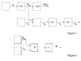
- Figure 1 schematically indicates the relation between signals occurring in a dead reckoning navigation device using inertial measurements.
- the measured angular velocity ⁇ is numerically integrated yielding the orientation of the vehicle body ⁇ .
- the orientation ⁇ is used to calculate a so-called rotation matrix R be (usually this integration is done such that it yields directly R be ).
- R be so-called rotation matrix
- the acceleration vector a b measured with respect to the vehicle body frame axis (indicated with a subscript b)
- the inertial acceleration vector ⁇ e (indicated by a subscript e) is now numerically integrated twice to obtain the velocity v e of the body and the position p e , both with respect to an inertial frame.
- the initial state i.e. velocity, position and orientation of a vehicle or person carrying the navigation device
- the measured acceleration is biased. Accordingly this will result in a drift of the measured position and velocity relative to the real values.
- Figure 2 shows another example of a dead-reckoning navigation device, wherein the velocity of the vehicle is determined by an odometer, and the orientation of the vehicle is determined by a compass.
- a bias error may be present, e.g. by a slipping of a wheel from which the odometer estimates the speed, which will result in a drift of the estimated position from the real position.
- Other navigation devices may determine a position by measuring a step-count of a person carrying the navigation device. Also here a bias error may be present.
- a cooperative dead-reckoning navigation system comprising dead-reckoning navigation devices that are capable to cooperate with each other.
- the navigation devices in the navigation system carry out a cooperative navigation method.
- at least one first dead-reckoning navigation device comprised in the dead-reckoning navigation system communicates its estimation of its position to at least one second navigation device in the navigation system.
- the second navigation device now has a pair of independent estimations for substantially the same position when the navigation devices encounter each other. From this pair of estimations the second navigation device may calculate an improved estimation of its position, e.g. by averaging the estimations of the pair.
- an equation can be formed. If sufficient equations are formed a plurality of bias errors can be determined, therewith improving further estimates.
- the wording "encounter” means that the navigation devices or persons or vehicles carrying the navigation devices are within proximity of each other. Two navigation devices are considered to be in each others proximity if they are within a predetermined range with respect to each other.
- the predetermined range depends on the required accuracy and on the practical means that are used to detect the encounter.
- the predetermined range may coincide with the detection range of an RFID detector.
- the predetermined range may for example be a sphere having a predetermined radius. Any object within that sphere will be considered as being within the predetermined range.
- Said predetermined radius may for example be in the order of 50 cm to 10 meter. With a substantially smaller radius, e.g. 10 cm, the probability that two vehicles spontaneously encounter each other is relatively small.
- the detection radius may be relatively small if desired. If the radius is much larger than 10 m, e.g. 50 m, the accuracy improvement is relatively small. Also situations are possible wherein a substantially larger radius may be acceptable.
- a submarine vessel having an accuracy of 1% will have a navigation error of 1 km after a travelled distance of 100 km. In that case an encounter with another submarine vessel also having a navigation device at a distance of 100 m may still be considered as proximate.
- a unidirectional transmission of navigation information allows the second navigation device to improve its navigation accuracy.
- the first navigation device may also improve its navigation accuracy if it receives navigation information from the second navigation device. However, alternatively it may improve its navigation accuracy by receiving a result obtained by the second navigation device. For example the second navigation device may estimate the bias error of the first navigation device and transmit this estimation to the first navigation device.
- a navigation device Preferably a navigation device only transmits its navigation information at positions where an encounter with another navigation device has taken place. It is possible to transmit navigation information more frequently but this would result in increased power consumption.
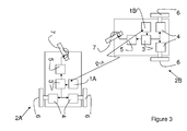
- FIG 3 shows a group of vehicles. For clarity only a first 2A and a second vehicle 2B are shown.
- Each of the vehicles 2A, 2B comprises a navigation device 1A, 1B respectively, as well as a drive mechanism 4 and steering mechanism 5 controlled by the navigation device 1, via a control unit 3.
- the control unit 3 uses navigation information retrieved from the navigation device 1 to control a driving speed with which the drive mechanism 4 drives back-wheels 6 and to control an orientation imposed by the steering mechanism 5 on the front wheel 7.
- Figure 4 shows in more detail an embodiment of the navigation devices 1A, 1B.
- the navigation devices 1A, 1B form a first and a second navigation device of a navigation system.
- the navigation system may comprise further navigation devices in addition to 1A and 1B.
- Each of the navigation devices 1A, 1B is capable of determining an initial estimation of its own position.
- the first navigation device 1A has a navigation module 10A that provides estimation p 1A .
- Second navigation device 1B has a navigation module 10B that provides estimation p 1B .
- the first navigation device 1A has a facility 20 for transmitting relevant navigation information "Info" to the second navigation device 1B.
- the transmitted relevant navigation information Info may include the estimation p 1A , but may also include other navigation information.
- the second navigation device 1B has a facility 30 for receiving the transmitted "Info".
- At least one of the navigation devices here the first navigation device 1A has a facility 40 for providing a proximity signal S pr that indicates whether the navigation devices 1A, 1B are within proximity of each other.
- the navigation module 10B of the second navigation device 1B has a dead reckoning facility for calculating the initial estimation p 1B of its position and a facility 50 for improving an accuracy of estimating its own position using the transmitted relevant navigation information Info provided by the first navigation device 1A for positions for which the proximity signal was given. This is symbolically illustrated by correction signal S C . In the sequel, the method for improving the accuracy will be described in more detail.
- the transmitted relevant navigation information "Info" may for example only comprise the initial estimation p 1A of the location of encounter as relevant navigation information. This is the case if the navigation module 10A is GPS based. If alternatively the navigation module 10A of the first navigation device 1A is also a dead-reckoning facility, it may transmit further relevant navigation information.
- the further relevant navigation information may comprise a double integrated rotation matrix if the navigation module is dead reckoning facility based on inertial sensor readings, or a single integrated rotation matrix if it is based on odometer readings. This additional relevant navigation information assists the second navigation device 1B to estimate the bias of the first navigation module 10A, and therewith to improve the estimation of its own bias. Examples of a dead-reckoning facility were described with reference to Figures 1 and 2 .
- the navigation device 1A is an altruistic device in that it merely transmits its own navigation information, without using information of others.
- Navigation device 1B on the other hand merely uses position estimation information used by others.
- Figure 5 shows a further embodiment. Parts therein corresponding to those in Figure 4 have a reference number that is 100 higher. Contrary to the previous embodiment, the second navigation device 1B transmits a correction signal S' c to the navigation module 110A of navigation device 101A that also enables the first navigation device 101A to improve its accuracy of the estimation of its position.
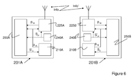
- FIG. 6 shows a still further embodiment. Parts therein corresponding to those in Figure 4 have a reference number that is 200 higher.
- each of the navigation devices 201A, 201B transmits its estimated position p 1A , p 1B and other relevant navigation information, if applicable, as relevant navigation information "Info, Info' " to the other one using bidirectional transmission facility 225A, 225B. If further navigation devices are present then the navigation devices 201A, 201B may also transmit their relevant navigation information to those other devices. Alternatively, the navigation devices may only use short distance transmission, so that they only exchange information when they encounter each other.
- each of the navigation devices 201A, 201B has its own proximity detector 240A, 240B that provide proximity detection signals S pr and S' pr respectively.
- the navigation devices 201A, 201B may transmit each other these proximity detection signals S pr and S' pr and generate an improved proximity detection signals S" pr by combining the signals in an AND-gate. In that way the risk of false detections is minimized.
- the right side of the last expression contains two terms.
- the first term is the evaluation of the true position of the object.
- the bias is placed outside the integrand since it is assumed constant.
- the integrand of the second term is known at the end of the integration time T and is derived from the gyro measurements. Double integration of the integrand results in a known constant matrix ⁇ ( T ).
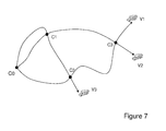
- Figure 7 shows a plurality of vehicles V1, V2, V3 each comprising a navigation device that traverse an inertial space. Occasionally, vehicles cross trajectories and encounter each other. They exchange information and at a later time they can use the information to estimate their sensor errors.
- crossing points C0, C1, C2, C3 are indicated by a dot and the trajectories by a line.
- the time of arrival of a vehicle at a crossing point with number j is denoted by Tj.
- Tj The time of arrival of a vehicle at a crossing point with number j.
- subscript k stands for the vehicle number and j stands for the j-th crossing point.
- p e , k i , j stands for the position indication of the INS of vehicle k at crossing point j and is further abbreviated to m k j .
- ⁇ k j stands for the evaluation of ⁇ ( T ) of vehicle k at the arrival time in crossing point j.
- Two encountering vehicles (for instance with numbers k1 and k2) exchange information about their ⁇ k j and m k j as the relevant navigation information Info, Info'. They also exchange information about ⁇ k j and m k j of all their previous encounters with other vehicles.
- the number of equations depends on the number of encounters between a limited set of vehicles.
- the number of unknowns i.e. the biases
- the number of equations may become equal or larger than the number of unknowns and the set of equations can be solved if the equations are independent of each other.
- the equations obtained are independent if the vehicles move independently and their trajectories are "complex" (i.e. several changes of directions and velocity changes).
- the first navigation device 1A transmits position information p1A corresponding to m A j in the equations above. If the navigation device 1A has a GPS-based navigation module 10A, then the data ⁇ A j does not exist. In that case 1B only has to solve the equation.
- One simulation involves three vehicles running "random" trajectories and having a total of three crossing points.
- This simulation resembles the scenario as depicted in Figure 7 above.
- a second simulation involves two vehicles in a so-called "satellite patrol" scenario, having two crossing points.
- Random the Random trajectory simulation is described.
- the simulation has been set-up as follows. For three vehicles, "random" trajectories are created, plotted in Figure 8 for the x-y plane.
- a set of waypoints is defined for each vehicle. These waypoints are indicated by a star in Figure 8 .
- the first waypoint of all three trajectories is the origin at coordinates (0,0).
- a polynomial trajectory is fitted on the waypoints such that the trajectory exactly passes through the waypoints.
- These polynomial trajectories are indicated with solid lines in the figure.
- An extra “hidden” waypoint is used at the origin making the derivative of the polynomial zero at the origin (this corresponds with starting the trajectory with zero velocity).
- the result is a set of three polynomials describing the three trajectories as a function of time.
- the trajectories for vehicles V2 and V3 cross each other at the crossing point. numbered C1 in the figure.
- the trajectories for vehicles V1 and V3 cross each other at crossing point C2.
- the trajectories for vehicles V1 and V2 cross each other at crossing point C3.
- the true vehicle locations are identical.
- the INS position indications of the respective vehicles obviously are not the same (indicated by the dashed lines in the figure).
- Information about crossing point C1 is stored in the memory of vehicles V2, V3. At crossing point C2, information about crossing point C1 is communicated to vehicle V1 by vehicle V3. Furthermore, information about crossing point C2 is stored in the memory of vehicles V1, V3. At crossing point C3, all information about the previous crossing points C1, C2 is available to vehicles V1, V2 and the biases of all three vehicles V1, V2, V3 can be solved.
- Figure 9 shows the true (random selected) biases and the estimated biases.
- Each star indicates the true (x,y) bias values of a vehicle.
- Each circle indicates the estimated (x,y) bias values of a vehicle.
- the bias estimation is not perfect. This is primarily due, however, to the imperfect INS-model used.
- the vehicles only exchange information with another vehicle that they encounter. Accordingly, in this embodiment, although the bias of vehicle V3 can be calculated at the third crossing point C3 by vehicles V1, V2, this information is not available to vehicle V3. Alternatively, however, the vehicles may use long distance communication, so that they always have the same information about previous crossing points available.
- the simulation set-up is the same as in the previous paragraph.
- the first vehicle V1 runs a more or less straight trajectory indicated by a first solid line in Figure 10 .
- a second vehicle V2 follows a trajectory that "orbits" about the trajectory of the first vehicle V1 and is indicated by a second solid line in Figure 10 .
- the (ideal) INS position indications for both vehicles are represented by the dotted lines. These coincide substantially with the true trajectories.
- the biased, INS-position indications V1B, V2B are represented by the dashed line and have strong deviations from the true trajectories.
- both vehicles Besides the origin C0, both vehicles have two crossing points C1, C2.
- two equations can be set-up and two sets of biases can be estimated.
- the results are presented in Figure 11 .
- the stars indicate the true x- and y-values of the sensor biases.
- the red circles indicate the estimated x- and y-values of the sensor biases.
- the imperfect estimation is primarily due to INS integration errors.
Landscapes
- Engineering & Computer Science (AREA)
- Radar, Positioning & Navigation (AREA)
- Remote Sensing (AREA)
- Physics & Mathematics (AREA)
- General Physics & Mathematics (AREA)
- Computer Networks & Wireless Communication (AREA)
- Automation & Control Theory (AREA)
- Navigation (AREA)
Abstract
A navigation system is described comprising at least a first and a second navigation device (201A, 201B) that each is capable of determining an initial estimation (p1A, p1B) of their own position,
- the first navigation device (201A) having a facility (225A) for transmitting its relevant navigation information (p1A) to the second navigation device (201B),
- the second navigation device (201B) having a facility (225B) for receiving the relevant navigation information (p1A),
- at least one of the first and second navigation device (201A, 201B) having a facility (210A, 210B) for providing a proximity signal (Spr, S'pr) that indicates whether the first and second navigation device are within proximity of each other,
- the second navigation device having a dead reckoning facility (210B) for calculating the initial estimation (p1B) of its position and a facility (250B) for improving an accuracy of estimating its own position using relevant navigation information (p1A) provided by the first navigation device (201 A) for positions for which the proximity signal (Spr) was given.
- the first navigation device (201A) having a facility (225A) for transmitting its relevant navigation information (p1A) to the second navigation device (201B),
- the second navigation device (201B) having a facility (225B) for receiving the relevant navigation information (p1A),
- at least one of the first and second navigation device (201A, 201B) having a facility (210A, 210B) for providing a proximity signal (Spr, S'pr) that indicates whether the first and second navigation device are within proximity of each other,
- the second navigation device having a dead reckoning facility (210B) for calculating the initial estimation (p1B) of its position and a facility (250B) for improving an accuracy of estimating its own position using relevant navigation information (p1A) provided by the first navigation device (201 A) for positions for which the proximity signal (Spr) was given.
Description
- The present invention relates to a navigation method,
- The present invention further relates to a navigation system,
- The present invention further relates to a navigation device,
- The present invention further relates to a vehicle provided with a navigation device,
- The present invention further relates to a group of vehicles.
- Nowadays GPS navigation facilities are available that can relatively accurately determine a position of a vehicle. However, in some circumstances alternative navigation methods are required as GPS-navigation signals are not always available, for example at locations below sea level and in buildings. One such alternative method applies dead-reckoning using data obtained from inertial sensors. Inertial sensors comprise gyroscopes and accelerometers. Gyroscopes provide information about the orientation of the vehicle and accelerometers provide information about its acceleration. If the initial position and velocity of a vehicle are known, its momentaneous velocity and position can be estimated by numerical integration of the acceleration and orientation data obtained from the accelerometers and gyroscopes. Generally accelerometers have a systematic error, also denoted as bias, resulting in a drift in position indication, exponential in time. Accordingly, such navigation devices based on inertial sensors need to be calibrated periodically to measure and compensate the sensor biases. With low-cost sensors, and without bias compensation, the navigation solution becomes useless within minutes. This also applies to dead reckoning methods using other sensors, e.g. odometers for measuring speed and a compass for measuring direction.
- In "A distributive algorithm for cooperative navigation among multiple robots" by Sanderson. Advanced robotics ISSN 0169-1864, 98, vol. 12, (17 ref.), pp. 335-349, a method is described for improving the navigation accuracy of robots by sensing of relative inter-robot positions and intercommunication of position estimates and planned trajectories. Although in this way a potentially better navigation result can be obtained than would be the case if the robots navigated independently, the method is complicated and the measurement of relative position may form another source of errors.
- Accordingly, there is a need for improvement.
- According to a first aspect of the invention a method of cooperative navigation is provided, comprising the steps of
- a. providing at least a first and a second navigation device, each capable of estimating their own position using a dead-reckoning method,
- b. independently moving the first and the second navigation device in a shared area,
- c. detecting whether the first and the second navigation device are in proximity of each other,
- d. if the detection is positive communicating navigation information obtained by the first navigation device at the moment of said detection to the second navigation device,
- e. improving an accuracy of the second navigation device using the position estimation received from the first navigation device.
- According to a second aspect of the invention a navigation system is provided comprising at least a first and a second navigation device that each has a dead-reckoning facility for determining a first initial estimation of their own position,
- the first navigation device having a facility for transmitting its navigation information to the second navigation device,
- the second navigation device having a facility for receiving the transmitted initial estimation,
- at least one of the first and second navigation device having a facility for providing a proximity signal that indicates whether the first and second navigation device are within proximity of each other,
- the second navigation device having a facility for improving the accuracy of estimating its own position using the navigation information provided by the first navigation device for positions for which the proximity signal was given.
- According to the above-mentioned aspects of the invention, the updating of the first initial estimation is exclusively based on the comparison of navigation information between vehicles obtained at the moment of encounters between them. This latter method allows for a substantially simpler implementation while having good results. In the method according to the present invention it is not necessary to have expensive facilities for determining a relative position. It is sufficient to have a simple proximity sensor, e.g. a sensor that merely provides for a binary signal indicative whether there is an encounter or not. Such a sensor may be based for example on RF technology. Furthermore, the calculation of the improved navigation result is simplified, as in case of an encounter the real coordinates of the vehicles have substantially the same value. Accordingly for each encounter the difference between the estimated positions of the vehicles is substantially determined by the bias errors in the sensors used for navigation. If a sufficient number of encounters have taken place, then the bias terms can be solved. It is not necessary that at least the same number of encounters occur as the number of bias terms. If for example ten vehicles are present, but two vehicles thereof have two encounters, this provides for sufficient information for these two vehicles, to estimate their biases and therewith improve their state estimation. The information retrieved from these encounters may be exchanged with other vehicles with which said two vehicles later have encounters.
- The relevant navigation information to be transferred by the first navigation device to the second navigation device may be an estimation of the position of the location of encounter by the first navigation device. If the estimation of the first navigation device is substantially bias free, this information is sufficient for the second navigation device to estimate its bias, and therewith to improve its own position estimation. If the estimation of the first navigation device is also subject to a bias, the first navigation device may additional information, such as the twice integrated orientation matrix in case of a dead reckoning device based on an inertial sensor or a single integrated orientation matrix in case of a dead reckoning device using odometer signals. In this case where the estimation of the first navigation device is also biased, both the bias of the first and of the second navigation can be estimated provided that the first and the navigation device have at least two encounters.
- In other words, the first and the second navigation determine their bias factors by solving a system of equations formed using each others relevant navigation information obtained in a plurality of cases where proximity was detected.
- The first navigation device may have a sensor that detects proximity, indicating whether the second navigation device is within proximity of the first navigation device. The proximity signal may initiate the first navigation device to transmit its relevant navigation information. A receiver in the second navigation device receives this relevant information. In this case the receiver also forms a facility for generating a proximity signal in the second navigation device, as the receiving of the information is an indication that it is within the proximity of the first navigation device. Alternatively the second navigation device may have an independent facility for providing the proximity signal, and the first may permanently broadcast its navigation information. Once proximity is detected by the facility of the second device, the latter may accept the broadcasted navigation information to be used for improvement of its own position estimation accuracy.
- Preferably each navigation device has its own proximity sensor. In that case it may be verified whether each of the proximity sensors indicates proximity. This reduces the risk of a false alarm, i.e. unjustified proximity detection. Such unjustified proximity detection would result in an incorrect estimation of bias factors.
- In the above-mentioned navigation system the first navigation device may use any means to estimate its own position, for example on the basis of GPS signals, or on the basis of a dead reckoning device or a combination thereof. The second navigation device is presumed to have a dead reckoning device, and uses the received relevant navigation information to determine its bias. However, it is alternatively possible that both navigation devices are provided with a dead reckoning device and that they exchange relevant navigation information with each other so that they can both estimate their biases and improve their navigation accuracy. It will be understood that apart from the first and the second also third and further navigation devices may be present that interact with each other and with the first and the second navigation device in a way similar to the way that the first and the second navigation device interact.
- According to a third aspect a navigation device is provided comprising
- a dead-reckoning facility for determining an initial estimation of its own position and other relevant navigation information,
- a facility for providing a proximity signal that indicates whether the navigation device is within a proximity of another navigation device,
- a facility for receiving relevant navigation information transmitted by another navigation device,
- a facility for improving an accuracy of estimating its own position using one or more sets of received navigation information, including initial position estimations, for positions for which the proximity signal was given.
- It is favorable that the relevant navigation information such as initial position estimations is not only provided unilaterally. Accordingly, in an embodiment the navigation device further comprises a facility for transmitting its initial position estimation and other relevant navigation information, so that the navigation device can also help other navigation devices to improve their position estimation. This also improves the reliability of the initial position estimations that the other navigation devices provide to the navigation device.
- The invention is in particularly suitable for use in vehicle. The vehicle is for example a bicycle, car, motorcycle, train, ship, boat, or aircraft. Preferably the vehicle comprises a drive and steering mechanism controlled by the navigation device. The vehicle may comprise a further navigation facility such as a GPS receiver, or an odometer, for providing information relating to a state of the vehicle. A combination facility may be present for combining the object-state signal of the navigation device with the information provided by the further navigation facility. The combination facility may for example select the most reliable information for navigation.
- In an embodiment thereof, the vehicle further comprises a drive and steering mechanism that is controlled by the navigation device. The vehicles may operate in a group that comprises at least a first vehicle with the navigation device and a second vehicle with the similar navigation device. Each time that the vehicles encounter each other, their navigation devices generate a proximity signal. The proximity signal indicates that a new combination of first and second estimations of the respective coordinate systems of the vehicles can be used to improve the estimation of the state of their respective coordinate systems. The estimation can be improved for example by determining an average value of the estimated positions, but can also be used more structurally to determine bias components of the navigation devices, which also results in an improved estimation of the states of the coordinate systems.
- If the vehicles operate in a relatively small space no particular measures are necessary to guarantee that the vehicles encounter each other relatively often. In an embodiment the vehicles further comprise a controller that forces regular encounters between the vehicles. In this way also in larger environments it can be assured that encounters between vehicles occur with a sufficiently high frequency to enable a desired level of improvement of the navigation accuracy.
- In a further embodiment at least the navigation device comprises a memory for storing relevant navigation information for previous detections of proximity, and the navigation device is arranged to communicate the stored relevant navigation information to a further similar navigation device when it is in proximity of the further similar navigation device. The further similar navigation device can use this communicated information to further improve its performance. The stored relevant navigation information comprises the relevant navigation information obtained by the navigation device itself and the navigation information received from similar devices which it encountered. Alternatively the navigation device may broadcast the relevant navigation information to any other navigation device, regardless its distance to the navigation device. However, if the similar navigation device stores the relevant navigation information and transmits this information once it is in proximity of the further similar navigation device, then the navigation devices do not need long range communication facilities, which is favorable for low power consumption. Two navigation devices may even exchange their navigation information indirectly, for example a first and a second navigation device may have navigation information resulting from an encounter with each other. If one of them encounters a third navigation device it may transfer this information to the third navigation device, and this third navigation device may on its turn transfer this information together with collected information of other encounters to a fourth navigation during an encounter therewith.
- It is not necessary that the navigation device is part of a vehicle. It may alternatively be used as a standalone device. For example firemen may carry the device to navigate within a building obscured by smoke.
- It should be noted that the signal processing functions by the navigation device can be implemented in hardware, software, or a combination of both.
- These and other aspects are described in more detail with reference to the drawing. Therein:
-
Figure 1 shows a first embodiment of a dead-reckoning navigation module, -
Figure 2 shows a second embodiment of a dead-reckoning navigation module, -
Figure 3 shows a pair of vehicles having mutually cooperating navigation devices, -
Figure 4 shows a first embodiment of a navigation system according to the invention, -
Figure 5 shows a second embodiment of a navigation system according to the invention, -
Figure 6 shows a third embodiment of a navigation system according to the invention, -
Figure 7 shows an example of vehicles having mutually crossing trajectories, -
Figure 8 shows trajectories for a plurality of vehicles, as well as paths determined by biased estimators in a first simulation, -
Figure 9 compares the simulated biases with the bias as estimated with a method according to the present invention, -
Figure 10 shows trajectories of simulated vehicles in a second simulation, -
Figure 11 compares the simulated biases with the bias as estimated with a method according to the present invention in this second simulation. -
Figure 1 schematically indicates the relation between signals occurring in a dead reckoning navigation device using inertial measurements. First, the measured angular velocityω is numerically integrated yielding the orientation of the vehicle body θ. The orientation θ is used to calculate a so-called rotation matrix R be (usually this integration is done such that it yields directly R be ). With this matrix, the acceleration vectora b , measured with respect to the vehicle body frame axis (indicated with a subscript b), is rotated to an inertial frame. The inertial acceleration vectorα e (indicated by a subscript e) is now numerically integrated twice to obtain the velocityv e of the body and the positionp e , both with respect to an inertial frame. - Provided that the initial state, i.e. velocity, position and orientation of a vehicle or person carrying the navigation device is known, it is potentially possible to determine the state at any later point in time. However, in practice the measured acceleration is biased. Accordingly this will result in a drift of the measured position and velocity relative to the real values.
-
Figure 2 shows another example of a dead-reckoning navigation device, wherein the velocity of the vehicle is determined by an odometer, and the orientation of the vehicle is determined by a compass. In this only one integration step is necessary to determine the position. Also in this case a bias error may be present, e.g. by a slipping of a wheel from which the odometer estimates the speed, which will result in a drift of the estimated position from the real position. Other navigation devices may determine a position by measuring a step-count of a person carrying the navigation device. Also here a bias error may be present. - According to the present invention a cooperative dead-reckoning navigation system is provided comprising dead-reckoning navigation devices that are capable to cooperate with each other. In other words the navigation devices in the navigation system carry out a cooperative navigation method. To that end at least one first dead-reckoning navigation device comprised in the dead-reckoning navigation system communicates its estimation of its position to at least one second navigation device in the navigation system. The second navigation device now has a pair of independent estimations for substantially the same position when the navigation devices encounter each other. From this pair of estimations the second navigation device may calculate an improved estimation of its position, e.g. by averaging the estimations of the pair. Moreover, from each pair of estimations an equation can be formed. If sufficient equations are formed a plurality of bias errors can be determined, therewith improving further estimates.
- The wording "encounter" means that the navigation devices or persons or vehicles carrying the navigation devices are within proximity of each other. Two navigation devices are considered to be in each others proximity if they are within a predetermined range with respect to each other. The predetermined range depends on the required accuracy and on the practical means that are used to detect the encounter. For example the predetermined range may coincide with the detection range of an RFID detector. The predetermined range may for example be a sphere having a predetermined radius. Any object within that sphere will be considered as being within the predetermined range. Said predetermined radius may for example be in the order of 50 cm to 10 meter. With a substantially smaller radius, e.g. 10 cm, the probability that two vehicles spontaneously encounter each other is relatively small. Therewith also the amount of information that can be exchanged and that can be used to improve the estimation accuracy is small. However, in case that deliberate encounters between the vehicles are arranged, this is not a problem. In that case the detection radius may be relatively small if desired. If the radius is much larger than 10 m, e.g. 50 m, the accuracy improvement is relatively small. Also situations are possible wherein a substantially larger radius may be acceptable. A submarine vessel having an accuracy of 1%, will have a navigation error of 1 km after a travelled distance of 100 km. In that case an encounter with another submarine vessel also having a navigation device at a distance of 100 m may still be considered as proximate. It is true that an error is made by assuming that the navigation devices of the two encountering submarine vessels are at the same position, and consequently this error will also cause an error in the estimation of the bias factors of the navigation systems. However, as the error (100 m) made in this assumption is substantially smaller than the practically occurring navigation errors (1km), still a more accurate estimation of the bias factors is obtained, therewith improving navigation accuracy. Likewise, navigating robots in a building may have a navigation error incrementing to tens of meters. In that case a distance of some meters may be considered proximate. It is sufficient that
- the navigation device has some binary decision facility that determines whether an other navigation system is proximate or not and,
- if the other navigation device is considered proximate, then it is assumed that the positions estimated by the encountering navigation devices are estimations for the same position, and the navigation information of the other navigation device is used,
- if the other navigation device is not considered proximate, the navigation information of the other navigation device is not used. (Although earlier stored navigation relating to earlier encounters stored by the other navigation device may be used.)
- A unidirectional transmission of navigation information allows the second navigation device to improve its navigation accuracy. The first navigation device may also improve its navigation accuracy if it receives navigation information from the second navigation device. However, alternatively it may improve its navigation accuracy by receiving a result obtained by the second navigation device. For example the second navigation device may estimate the bias error of the first navigation device and transmit this estimation to the first navigation device.
- Preferably a navigation device only transmits its navigation information at positions where an encounter with another navigation device has taken place. It is possible to transmit navigation information more frequently but this would result in increased power consumption.
-
Figure 3 shows a group of vehicles. For clarity only a first 2A and asecond vehicle 2B are shown. Each of thevehicles navigation device drive mechanism 4 andsteering mechanism 5 controlled by thenavigation device 1, via acontrol unit 3. Thecontrol unit 3 uses navigation information retrieved from thenavigation device 1 to control a driving speed with which thedrive mechanism 4 drives back-wheels 6 and to control an orientation imposed by thesteering mechanism 5 on thefront wheel 7.
Figure 4 shows in more detail an embodiment of thenavigation devices navigation devices navigation devices first navigation device 1A has anavigation module 10A that provides estimation p1A.Second navigation device 1B has anavigation module 10B that provides estimation p1B. In the navigation system thefirst navigation device 1A has afacility 20 for transmitting relevant navigation information "Info" to thesecond navigation device 1B. Dependent on the type ofnavigation modules 10A ofdevice 1A, the transmitted relevant navigation information Info may include the estimation p1A, but may also include other navigation information. Thesecond navigation device 1B has afacility 30 for receiving the transmitted "Info". At least one of the navigation devices, here thefirst navigation device 1A has afacility 40 for providing a proximity signal Spr that indicates whether thenavigation devices navigation module 10B of thesecond navigation device 1B has a dead reckoning facility for calculating the initial estimation p1B of its position and afacility 50 for improving an accuracy of estimating its own position using the transmitted relevant navigation information Info provided by thefirst navigation device 1A for positions for which the proximity signal was given. This is symbolically illustrated by correction signal SC. In the sequel, the method for improving the accuracy will be described in more detail. - In the embodiment shown in
Figure 4 it is not relevant how thenavigation module 10A of thefirst navigation device 1A calculates the initial estimation p1A for its position. Dependent on the nature of thenavigation device 1A, the transmitted relevant navigation information "Info" may for example only comprise the initial estimation p1A of the location of encounter as relevant navigation information. This is the case if thenavigation module 10A is GPS based. If alternatively thenavigation module 10A of thefirst navigation device 1A is also a dead-reckoning facility, it may transmit further relevant navigation information. The further relevant navigation information may comprise a double integrated rotation matrix if the navigation module is dead reckoning facility based on inertial sensor readings, or a single integrated rotation matrix if it is based on odometer readings. This additional relevant navigation information assists thesecond navigation device 1B to estimate the bias of thefirst navigation module 10A, and therewith to improve the estimation of its own bias. Examples of a dead-reckoning facility were described with reference toFigures 1 and 2 . - In the embodiment of
Figure 4 , thenavigation device 1A is an altruistic device in that it merely transmits its own navigation information, without using information of others.Navigation device 1B on the other hand merely uses position estimation information used by others. -
Figure 5 shows a further embodiment. Parts therein corresponding to those inFigure 4 have a reference number that is 100 higher. Contrary to the previous embodiment, thesecond navigation device 1B transmits a correction signal S'c to thenavigation module 110A ofnavigation device 101A that also enables thefirst navigation device 101A to improve its accuracy of the estimation of its position. -
Figure 6 shows a still further embodiment. Parts therein corresponding to those inFigure 4 have a reference number that is 200 higher. In the embodiment shown inFigure 6 each of thenavigation devices bidirectional transmission facility navigation devices - Furthermore, each of the
navigation devices navigation devices - A way in which the exchanged position information can be used to improve the accuracy of position estimation is now described in more detail with reference to
Figures 7-11 . - It is assumed that there are several users/vehicles V1, V2, V3 (
Figure 7 ) etc. travelling in an inertial space. Each of these users is equipped with a strap-down inertial navigation device. The errors on attitude measurement are assumed to be negligible. Regularly vehicles trajectories cross and vehicles encounter each other at crossing points C1, C2, C3. The encounter itself is detected by the vehicles by some device (for instance a short range radio communication device). At the moment of the encounter it is assumed that the positions of both vehicles are the same.
Furthermore, in the next simplified mathematical derivation it is assumed that no other errors are present besides some bias error on the accelerometers.
In practice, numerical integration in the inertial system (INS) of each vehicle is done by summing. If errors due to this approximation of numerical integration are neglected, the reading of the INS may be evaluated as: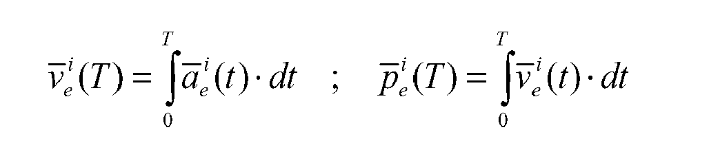
- With

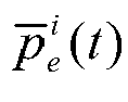


- The measured acceleration in the inertial frame is derived from the acceleration measured in the body frame using the time varying rotation matrix R be (t) :

- It then follows:

- If noise and other measurement errors are neglected for now, and it is assumed that the accelerometer bias is the major error contributor, the measured acceleration may be written as the sum of the ideal (true) acceleration (superscript t) and the measurement bias, which is assumed constant:

- For the position indication of the INS it then follows:


- The right side of the last expression contains two terms. The first term is the evaluation of the true position of the object. In the second term, the bias is placed outside the integrand since it is assumed constant. The integrand of the second term is known at the end of the integration time T and is derived from the gyro measurements. Double integration of the integrand results in a known constant matrix θ(T). The equation for the position indication of the INS at time T can now be further simplified to:

- Now suppose multiple vehicles are traversing an inertial space. Each vehicle has its own INS. Occasionally vehicles may cross trajectories and encounter each other. Each vehicle has its unique identification number and each crossing point is also given a unique number (1,2 ,3, etc.). An example situation is given in
Figure 7 . -
Figure 7 shows a plurality of vehicles V1, V2, V3 each comprising a navigation device that traverse an inertial space. Occasionally, vehicles cross trajectories and encounter each other. They exchange information and at a later time they can use the information to estimate their sensor errors. - In the figure, crossing points (C0, C1, C2, C3) are indicated by a dot and the trajectories by a line. By way of example, all vehicles V1, V2, V3 start their trajectory in the origin (=crossing point C1). The time of arrival of a vehicle at a crossing point with number j is denoted by Tj. Lets assume all time varying variables are evaluated at time Tj and we use a superscript j to denote this. Now the general expression for the position indicated by the INS of vehicle Vk is:
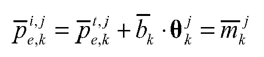
- In this expression subscript k stands for the vehicle number and j stands for the j-th crossing point. So,


- It is assumed that all vehicles V1, V2, V3 have an encounter detection facility that can detect the encounter (for example a simple radio device with limited transmission range). There may even be a strategy that the vehicles deliberately try to encounter in order to increase their navigation accuracy. Furthermore it is assumed that the vehicles can exchange information with each other.
- Two encountering vehicles (for instance with numbers k1 and k2) exchange information about their


- Since the number of encounters grows unlimited (theoretically), the number of available equations also does. Now, all two equations involving the same crossing point are subtracted from each other. Obviously,


- The number of equations depends on the number of encounters between a limited set of vehicles. The number of unknowns (i.e. the biases) is limited and is equal to the number of vehicles. So, after some time, the number of equations may become equal or larger than the number of unknowns and the set of equations can be solved if the equations are independent of each other. The equations obtained are independent if the vehicles move independently and their trajectories are "complex" (i.e. several changes of directions and velocity changes).
- In the case illustrated and described with reference to
Figure 4 only thefirst navigation device 1A transmits position information p1A corresponding to
navigation device 1A has a GPS-basednavigation module 10A, then the data
case 1B only has to solve the equation. -

navigation device 1A is the position
- To illustrate the mathematical principle, the example in
Figure 7 is taken. The resulting set of equations for this example would be:
- Two simulations were carried out to verify correct operation of the present invention. One simulation involves three vehicles running "random" trajectories and having a total of three crossing points.
- This simulation resembles the scenario as depicted in
Figure 7 above. A second simulation involves two vehicles in a so-called "satellite patrol" scenario, having two crossing points. - First the Random" trajectory simulation is described. The simulation has been set-up as follows. For three vehicles, "random" trajectories are created, plotted in
Figure 8 for the x-y plane. First, a set of waypoints is defined for each vehicle. These waypoints are indicated by a star inFigure 8 . The first waypoint of all three trajectories is the origin at coordinates (0,0). A polynomial trajectory is fitted on the waypoints such that the trajectory exactly passes through the waypoints. These polynomial trajectories are indicated with solid lines in the figure. An extra "hidden" waypoint is used at the origin making the derivative of the polynomial zero at the origin (this corresponds with starting the trajectory with zero velocity). The result is a set of three polynomials describing the three trajectories as a function of time. - From these polynomials, the time derivative polynomials and double time derivative polynomials are derived, corresponding with the exact velocity and acceleration of the three vehicles as a function of time. This results in three sets of three polynomials each, describing the vehicle position, velocity and acceleration as a function of time. All polynomials have been evaluated at discrete time instances (i.e., they are sampled). From the sampled velocity, the exact sampled vehicle attitude (heading) is derived:
θ = atan 2(νy ν x ), wherein atan2(*) is the four quadrant arctangent function. From the exact acceleration and attitude, the exact acceleration in the body axis system is derived. The attitude and body axis acceleration calculated in this way is used to simulate an INS system. In the simulation discussed here, a simple INS is used involving straightforward integration using Euler integration steps. Alternatively however a more exact integration method may be used. - The result of this simple INS (i.e., the vehicle trajectories) is indicated in
Figure 8 with dotted lines. As can be seen the INS trajectories coincide substantially with the ideal polynomial trajectories. The small differences are the result of numerical integration errors and can be made arbitrarily small by making the time steps smaller. Furthermore, a measured body acceleration was simulated by adding bias terms to the true body acceleration. Numerical integrating again, this results in the erroneous INS trajectory indication, plotted inFigure 8 with dashed lines. - As can be seen from
Figure 8 , the trajectories for vehicles V2 and V3 cross each other at the crossing point. numbered C1 in the figure. The trajectories for vehicles V1 and V3 cross each other at crossing point C2. The trajectories for vehicles V1 and V2 cross each other at crossing point C3. At the crossing points, the true vehicle locations are identical. The INS position indications of the respective vehicles obviously are not the same (indicated by the dashed lines in the figure). - Information about crossing point C1 is stored in the memory of vehicles V2, V3. At crossing point C2, information about crossing point C1 is communicated to vehicle V1 by vehicle V3. Furthermore, information about crossing point C2 is stored in the memory of vehicles V1, V3. At crossing point C3, all information about the previous crossing points C1, C2 is available to vehicles V1, V2 and the biases of all three vehicles V1, V2, V3 can be solved.
- To illustrate this communication process, the memory content of all three vehicles V1, V2, V3 at the three successive crossing points C1, C2, C3 is given in the following Table. The numbers indicate the crossing point about which information is available.
Vehicle V1 Vehicle V2 Vehicle V3 C0 (origin) Empty Empty Empty C1 Empty 1 1 C2 1,2 1 1,2 C3 1,2,3 1,2,3 1,2 - At crossing point C3, enough information is available to vehicles V1, V2 and the biases can be solved.
Figure 9 shows the true (random selected) biases and the estimated biases. Each star indicates the true (x,y) bias values of a vehicle. Each circle indicates the estimated (x,y) bias values of a vehicle. As can be seen, the bias estimation is not perfect. This is primarily due, however, to the imperfect INS-model used. - In this embodiment it is presumed that the vehicles only exchange information with another vehicle that they encounter. Accordingly, in this embodiment, although the bias of vehicle V3 can be calculated at the third crossing point C3 by vehicles V1, V2, this information is not available to vehicle V3. Alternatively, however, the vehicles may use long distance communication, so that they always have the same information about previous crossing points available.
- In a second simulation, denoted as "Satellite patrol" trajectory simulation, only two vehicles are involved. The simulation set-up is the same as in the previous paragraph. The first vehicle V1 runs a more or less straight trajectory indicated by a first solid line in
Figure 10 . A second vehicle V2 follows a trajectory that "orbits" about the trajectory of the first vehicle V1 and is indicated by a second solid line inFigure 10 . - The (ideal) INS position indications for both vehicles are represented by the dotted lines. These coincide substantially with the true trajectories. The biased, INS-position indications V1B, V2B are represented by the dashed line and have strong deviations from the true trajectories. Besides the origin C0, both vehicles have two crossing points C1, C2. At the second crossing point, two equations can be set-up and two sets of biases can be estimated. The results are presented in
Figure 11 . Therein the stars indicate the true x- and y-values of the sensor biases. The red circles indicate the estimated x- and y-values of the sensor biases. The imperfect estimation is primarily due to INS integration errors.
Claims (14)
- Method of cooperative navigation, comprising the steps ofa. providing at least a first and a second navigation device, at least the second navigation device being capable of estimating its own position using a dead-reckoning method,b. independently moving the first and the second navigation device in a shared environment,c. detecting whether the first and the second navigation device are in proximity of each other,d. if the detection is positive communicating relevant navigation information obtained by the first navigation device at the moment of said detection to the second navigation device,e. improving an accuracy of the second navigation device using the relevant navigation information received from the first navigation device.
- Method according to claim 1, wherein the first and the second navigation device exchange relevant navigation information with each other when proximity between the first and the second navigation device is detected and the first and the second navigation device determine their bias factors by solving a system of equations formed using each others relevant navigation information obtained in a plurality of cases where a proximity was detected.
- Navigation system comprising at least a first and a second navigation device (1A, 1B; 101A, 101B; 201A, 201B) that each are capable of determining an initial estimation (p1A, p1B) of their own position,- the first navigation device having a facility for transmitting relevant navigation information to the second navigation device,- the second navigation device having a facility for receiving the transmitted relevant navigation information,- at least one of the first and second navigation device having a facility for providing a proximity signal that indicates whether the first and second navigation device are within proximity of each other,- the second navigation device having a dead reckoning facility for calculating the initial estimation of its position and a facility for improving an accuracy of estimating its own position using relevant navigation information transmitted by the first navigation device for positions for which the proximity signal was given.
- Navigation system according to claim 3, wherein the first and the second navigation device exchange relevant navigation information with each other if they detect each others proximity and the first and the second navigation device determine their bias factors by solving a system of equations formed using each others relevant navigation information that was exchanged for a plurality of cases where a proximity was detected.
- Navigation device comprising- a dead-reckoning facility for determining an initial estimation of its own position,- a facility for providing a proximity signal that indicates whether the navigation device is within proximity of another navigation device,- a facility for receiving relevant navigation information transmitted by another navigation device,- a facility for improving an accuracy of estimating its own position using relevant navigation information transmitted for positions for which the proximity signal was given.
- Navigation device according to claim 5, further comprising a facility for transmitting relevant navigation information.
- Navigation device according to claim 5 or 6, wherein the facility for providing a proximity signal comprises a proximity sensor.
- Navigation device according to claim 5 or 6, wherein the facility for providing a proximity signal comprises a receiver that receives a proximity signal from said another navigation device.
- Navigation device according to claim 7, further comprising a GPS facility and a combination facility for combining navigation information obtained from the GPS facility with navigation information determined by the dead reckoning facility.
- Vehicle provided with a navigation device according to one of the claim 5 to 9.
- Vehicle according to claim 10, further comprising a drive and steering mechanism (4, 5) controlled by the navigation device.
- Group of vehicles according to claim 10 or 11, wherein the navigation devices form a navigation system as claimed in claim 2.
- Group of vehicles according to claim 12, wherein the vehicles further comprise a controller that forces regular encounters between the vehicles.
- Group of vehicles according to claim 12 or 13, at least one of which has a navigation device with a memory for storing relevant navigation information obtained from mutually independent navigation devices for positions at which a proximity signal was provided indicative for a proximity between said navigation devices.
Priority Applications (5)
| Application Number | Priority Date | Filing Date | Title |
|---|---|---|---|
| EP08170013A EP2219044A1 (en) | 2008-11-26 | 2008-11-26 | Navigation method, navigation system, navigation device, vehicle provided therewith and group of vehicles |
| CN200980154377.XA CN102272622B (en) | 2008-11-26 | 2009-11-26 | Navigation method, navigation system, navigation device, vehicle equipped with the navigation device, and group of vehicles |
| US13/131,404 US8548731B2 (en) | 2008-11-26 | 2009-11-26 | Navigation method, navigation system, navigation device, vehicle provided therewith and group of vehicles |
| PCT/NL2009/050722 WO2010062179A1 (en) | 2008-11-26 | 2009-11-26 | Navigation method, navigation system, navigation device, vehicle provided therewith and group of vehicles |
| EP09764616A EP2359158A1 (en) | 2008-11-26 | 2009-11-26 | Navigation method, navigation system, navigation device, vehicle provided therewith and group of vehicles |
Applications Claiming Priority (1)
| Application Number | Priority Date | Filing Date | Title |
|---|---|---|---|
| EP08170013A EP2219044A1 (en) | 2008-11-26 | 2008-11-26 | Navigation method, navigation system, navigation device, vehicle provided therewith and group of vehicles |
Publications (1)
| Publication Number | Publication Date |
|---|---|
| EP2219044A1 true EP2219044A1 (en) | 2010-08-18 |
Family
ID=40651373
Family Applications (2)
| Application Number | Title | Priority Date | Filing Date |
|---|---|---|---|
| EP08170013A Ceased EP2219044A1 (en) | 2008-11-26 | 2008-11-26 | Navigation method, navigation system, navigation device, vehicle provided therewith and group of vehicles |
| EP09764616A Withdrawn EP2359158A1 (en) | 2008-11-26 | 2009-11-26 | Navigation method, navigation system, navigation device, vehicle provided therewith and group of vehicles |
Family Applications After (1)
| Application Number | Title | Priority Date | Filing Date |
|---|---|---|---|
| EP09764616A Withdrawn EP2359158A1 (en) | 2008-11-26 | 2009-11-26 | Navigation method, navigation system, navigation device, vehicle provided therewith and group of vehicles |
Country Status (4)
| Country | Link |
|---|---|
| US (1) | US8548731B2 (en) |
| EP (2) | EP2219044A1 (en) |
| CN (1) | CN102272622B (en) |
| WO (1) | WO2010062179A1 (en) |
Cited By (2)
| Publication number | Priority date | Publication date | Assignee | Title |
|---|---|---|---|---|
| CN103518119A (en) * | 2011-03-24 | 2014-01-15 | 约翰逊控制技术公司 | System and method for transmitting vehicle operating data to an external navigation system |
| CN118226857A (en) * | 2024-03-29 | 2024-06-21 | 北京理工大学 | Terminal time cooperative control method for adaptive grouping of multiple unmanned vehicles |
Families Citing this family (15)
| Publication number | Priority date | Publication date | Assignee | Title |
|---|---|---|---|---|
| DE102012008867B4 (en) * | 2012-05-07 | 2021-01-21 | T-Mobile International Austria Gmbh | Method for improving the use of local area services in a public land-based cellular network, program and computer program product |
| US8433514B1 (en) * | 2012-05-17 | 2013-04-30 | Trimble Navigation, Limited | Navigation sensor mounting-angle calibration |
| US9057615B2 (en) * | 2012-10-26 | 2015-06-16 | Texas Instruments Incorporated | Systems and methods for navigating using corrected yaw bias values |
| US10054442B2 (en) * | 2013-01-17 | 2018-08-21 | Invensense, Inc. | Method and apparatus for handling vertical orientations of devices for constraint free portable navigation |
| US20140358434A1 (en) * | 2013-06-02 | 2014-12-04 | Hangzhou Haicun Information Technology Co. Ltd. | Peer-Assisted Dead Reckoning |
| JP6266254B2 (en) * | 2013-07-30 | 2018-01-24 | 株式会社日立国際八木ソリューションズ | Local wireless system, wireless terminal, local wireless system location switching method, and wireless terminal location switching method |
| US20150039224A1 (en) * | 2013-07-30 | 2015-02-05 | Here Global B.V. | Method and apparatus for detecting and sharing vehicle location |
| DE102014004060B4 (en) | 2014-03-10 | 2015-10-22 | Northrop Grumman Litef Gmbh | METHOD AND DEVICE FOR DETERMINING NAVIGATION DATA |
| CN106885567B (en) * | 2015-12-15 | 2020-04-03 | 华为技术有限公司 | A kind of inertial navigation cooperative positioning method and positioning device |
| GB2553141B (en) | 2016-08-26 | 2019-12-11 | Raytheon Systems Ltd | Method and apparatus for position estimation |
| US10971017B2 (en) | 2017-10-31 | 2021-04-06 | Cummins Inc. | Sensor fusion and information sharing using inter-vehicle communication |
| US10841746B2 (en) * | 2018-06-07 | 2020-11-17 | UST Global (Singapore) Pte. Ltd. | Group travel and map integration tool for online and offline connectivity and location tracking in real time |
| WO2020068043A1 (en) * | 2018-09-24 | 2020-04-02 | Science Applications International Corporation | System and method for dismounted assured position, navigation & timing (dapnt) |
| US10234538B1 (en) | 2018-09-24 | 2019-03-19 | Science Applications International Corporation | System and method for dismounted assured position, navigation and timing (DAPNT) |
| EP4176234B1 (en) * | 2020-09-11 | 2025-12-31 | Google LLC | DETECTION AND IMPROVEMENT OF SIMULTANEOUS NAVIGATION SESSIONS ON MULTIPLE DEVICES |
Citations (5)
| Publication number | Priority date | Publication date | Assignee | Title |
|---|---|---|---|---|
| WO2001027649A1 (en) * | 1999-10-08 | 2001-04-19 | Motorola, Inc. | Method and apparatus for transferring location estimates from a first transceiver to a second transceiver |
| WO2001090773A1 (en) * | 2000-05-25 | 2001-11-29 | Koninklijke Philips Electronics N.V. | A method of estimating the location of a device |
| US20030179133A1 (en) * | 2002-03-20 | 2003-09-25 | Gilles Pepin | Wireless handheld portabel navigation system and method for visually impaired pedestrians |
| US6801855B1 (en) * | 2002-06-28 | 2004-10-05 | Garmin Ltd. | Systems and methods with integrated GPS and dead reckoning capabilities |
| GB2443864A (en) * | 2006-11-15 | 2008-05-21 | Motorola Inc | A mobile station capable of reporting to a location server current location and that of a second mobile station detected to be near the first mobile station |
Family Cites Families (5)
| Publication number | Priority date | Publication date | Assignee | Title |
|---|---|---|---|---|
| US3509765A (en) | 1965-12-17 | 1970-05-05 | Gen Motors Corp | Inertial navigation system |
| AU2003278848A1 (en) * | 2002-09-23 | 2004-04-08 | Topcon Gps Llc | Position estimation using a network of global-positioning receivers |
| US20050197771A1 (en) * | 2004-03-04 | 2005-09-08 | Seick Ryan E. | Potential accident detection assessment wireless alert network |
| US7066004B1 (en) | 2004-09-02 | 2006-06-27 | Sandia Corporation | Inertial measurement unit using rotatable MEMS sensors |
| GB0427643D0 (en) | 2004-12-17 | 2005-01-19 | Carnall Murat | Method and apparatus for recording events |
-
2008
- 2008-11-26 EP EP08170013A patent/EP2219044A1/en not_active Ceased
-
2009
- 2009-11-26 EP EP09764616A patent/EP2359158A1/en not_active Withdrawn
- 2009-11-26 US US13/131,404 patent/US8548731B2/en not_active Expired - Fee Related
- 2009-11-26 CN CN200980154377.XA patent/CN102272622B/en not_active Expired - Fee Related
- 2009-11-26 WO PCT/NL2009/050722 patent/WO2010062179A1/en not_active Ceased
Patent Citations (5)
| Publication number | Priority date | Publication date | Assignee | Title |
|---|---|---|---|---|
| WO2001027649A1 (en) * | 1999-10-08 | 2001-04-19 | Motorola, Inc. | Method and apparatus for transferring location estimates from a first transceiver to a second transceiver |
| WO2001090773A1 (en) * | 2000-05-25 | 2001-11-29 | Koninklijke Philips Electronics N.V. | A method of estimating the location of a device |
| US20030179133A1 (en) * | 2002-03-20 | 2003-09-25 | Gilles Pepin | Wireless handheld portabel navigation system and method for visually impaired pedestrians |
| US6801855B1 (en) * | 2002-06-28 | 2004-10-05 | Garmin Ltd. | Systems and methods with integrated GPS and dead reckoning capabilities |
| GB2443864A (en) * | 2006-11-15 | 2008-05-21 | Motorola Inc | A mobile station capable of reporting to a location server current location and that of a second mobile station detected to be near the first mobile station |
Non-Patent Citations (2)
| Title |
|---|
| ARTHUR C. SANDERSON: "A distributed algorithm for cooperative navigfation among multiple mobile robots", ADVANCED ROBOTICS, vol. 12, no. 4, 1998, Japan, pages 335 - 349, XP002530333 * |
| SANDERSON.: "A distributive algorithm for cooperative navigation among multiple robots", ADVANCED ROBOTICS, vol. 12, no. 4, 1998, pages 313 - 481 |
Cited By (3)
| Publication number | Priority date | Publication date | Assignee | Title |
|---|---|---|---|---|
| CN103518119A (en) * | 2011-03-24 | 2014-01-15 | 约翰逊控制技术公司 | System and method for transmitting vehicle operating data to an external navigation system |
| US9140562B2 (en) | 2011-03-24 | 2015-09-22 | Claude Mignen | System and method for transferring vehicle operating data to an external navigation system |
| CN118226857A (en) * | 2024-03-29 | 2024-06-21 | 北京理工大学 | Terminal time cooperative control method for adaptive grouping of multiple unmanned vehicles |
Also Published As
| Publication number | Publication date |
|---|---|
| WO2010062179A1 (en) | 2010-06-03 |
| US20110288728A1 (en) | 2011-11-24 |
| CN102272622A (en) | 2011-12-07 |
| US8548731B2 (en) | 2013-10-01 |
| CN102272622B (en) | 2015-07-01 |
| EP2359158A1 (en) | 2011-08-24 |
Similar Documents
| Publication | Publication Date | Title |
|---|---|---|
| US8548731B2 (en) | Navigation method, navigation system, navigation device, vehicle provided therewith and group of vehicles | |
| EP3109589B1 (en) | A unit and method for improving positioning accuracy | |
| Yang et al. | Magnetometer and differential carrier phase GPS-aided INS for advanced vehicle control | |
| US10247576B2 (en) | Method and system for verifying measured data | |
| EP0870174B1 (en) | Improved vehicle navigation system and method using gps velocities | |
| EP2519803B1 (en) | Technique for calibrating dead reckoning positioning data | |
| EP1988408B1 (en) | Positioning system, positioning method and car navigation system | |
| JP3816018B2 (en) | Train own vehicle position detection method and train own vehicle position detection system | |
| EP1530024A1 (en) | Motion estimation method and system for mobile body | |
| EP1510832A1 (en) | GPS/dead reckoning combination system and operating method thereof | |
| US20160040992A1 (en) | Positioning apparatus and global navigation satellite system, method of detecting satellite signals | |
| EP3299765A1 (en) | Calibrating inertial navigation data using tire pressure monitoring system signals | |
| WO2014002211A1 (en) | Positioning device | |
| JP2021085880A (en) | Analysis of localization error in mobile object | |
| WO2016203744A1 (en) | Positioning device | |
| CN115790613B (en) | Visual information-assisted inertial/odometer combined navigation method and device | |
| JP2012098185A (en) | Azimuth angle estimation device and program | |
| US20140249750A1 (en) | Navigational and location determination system | |
| JP2009036651A (en) | Navigation device, navigation method, and navigation program | |
| US20100299059A1 (en) | Method for operating a navigation system and a navigation system | |
| RU2539131C1 (en) | Strapdown integrated navigation system of average accuracy for mobile onshore objects | |
| KR100586894B1 (en) | Determination method of vehicle's stationary state, vehicle navigation information generation method and vehicle navigation system | |
| JP4376738B2 (en) | Apparatus and method for detecting zero point error of angular velocity sensor | |
| CN114623839A (en) | Navigation method, system, device and storage medium | |
| KR101105144B1 (en) | Positioning method of moving object |
Legal Events
| Date | Code | Title | Description |
|---|---|---|---|
| PUAI | Public reference made under article 153(3) epc to a published international application that has entered the european phase |
Free format text: ORIGINAL CODE: 0009012 |
|
| AK | Designated contracting states |
Kind code of ref document: A1 Designated state(s): AT BE BG CH CY CZ DE DK EE ES FI FR GB GR HR HU IE IS IT LI LT LU LV MC MT NL NO PL PT RO SE SI SK TR |
|
| AX | Request for extension of the european patent |
Extension state: AL BA MK RS |
|
| STAA | Information on the status of an ep patent application or granted ep patent |
Free format text: STATUS: THE APPLICATION HAS BEEN REFUSED |
|
| 18R | Application refused |
Effective date: 20100925 |