EP2218914A2 - Scroll-type fluid machine - Google Patents
Scroll-type fluid machine Download PDFInfo
- Publication number
- EP2218914A2 EP2218914A2 EP10153580A EP10153580A EP2218914A2 EP 2218914 A2 EP2218914 A2 EP 2218914A2 EP 10153580 A EP10153580 A EP 10153580A EP 10153580 A EP10153580 A EP 10153580A EP 2218914 A2 EP2218914 A2 EP 2218914A2
- Authority
- EP
- European Patent Office
- Prior art keywords
- scroll
- axis
- eccentric pin
- bearing
- peripheral surface
- Prior art date
- Legal status (The legal status is an assumption and is not a legal conclusion. Google has not performed a legal analysis and makes no representation as to the accuracy of the status listed.)
- Withdrawn
Links
- 239000012530 fluid Substances 0.000 title claims abstract description 22
- 230000002093 peripheral effect Effects 0.000 claims abstract description 36
- 239000003507 refrigerant Substances 0.000 claims description 14
- 230000005484 gravity Effects 0.000 claims description 3
- 239000003921 oil Substances 0.000 description 20
- 238000000926 separation method Methods 0.000 description 12
- 230000006835 compression Effects 0.000 description 8
- 238000007906 compression Methods 0.000 description 8
- 239000010687 lubricating oil Substances 0.000 description 7
- 238000007789 sealing Methods 0.000 description 6
- 238000005057 refrigeration Methods 0.000 description 3
- 238000004519 manufacturing process Methods 0.000 description 2
- 238000005192 partition Methods 0.000 description 2
- 238000009825 accumulation Methods 0.000 description 1
- 238000010586 diagram Methods 0.000 description 1
- 239000000463 material Substances 0.000 description 1
- 230000000717 retained effect Effects 0.000 description 1
- 238000005096 rolling process Methods 0.000 description 1
Images



Classifications
-
- F—MECHANICAL ENGINEERING; LIGHTING; HEATING; WEAPONS; BLASTING
- F04—POSITIVE - DISPLACEMENT MACHINES FOR LIQUIDS; PUMPS FOR LIQUIDS OR ELASTIC FLUIDS
- F04C—ROTARY-PISTON, OR OSCILLATING-PISTON, POSITIVE-DISPLACEMENT MACHINES FOR LIQUIDS; ROTARY-PISTON, OR OSCILLATING-PISTON, POSITIVE-DISPLACEMENT PUMPS
- F04C18/00—Rotary-piston pumps specially adapted for elastic fluids
- F04C18/02—Rotary-piston pumps specially adapted for elastic fluids of arcuate-engagement type, i.e. with circular translatory movement of co-operating members, each member having the same number of teeth or tooth-equivalents
- F04C18/0207—Rotary-piston pumps specially adapted for elastic fluids of arcuate-engagement type, i.e. with circular translatory movement of co-operating members, each member having the same number of teeth or tooth-equivalents both members having co-operating elements in spiral form
- F04C18/0215—Rotary-piston pumps specially adapted for elastic fluids of arcuate-engagement type, i.e. with circular translatory movement of co-operating members, each member having the same number of teeth or tooth-equivalents both members having co-operating elements in spiral form where only one member is moving
-
- F—MECHANICAL ENGINEERING; LIGHTING; HEATING; WEAPONS; BLASTING
- F01—MACHINES OR ENGINES IN GENERAL; ENGINE PLANTS IN GENERAL; STEAM ENGINES
- F01C—ROTARY-PISTON OR OSCILLATING-PISTON MACHINES OR ENGINES
- F01C21/00—Component parts, details or accessories not provided for in groups F01C1/00 - F01C20/00
- F01C21/02—Arrangements of bearings
-
- F—MECHANICAL ENGINEERING; LIGHTING; HEATING; WEAPONS; BLASTING
- F04—POSITIVE - DISPLACEMENT MACHINES FOR LIQUIDS; PUMPS FOR LIQUIDS OR ELASTIC FLUIDS
- F04C—ROTARY-PISTON, OR OSCILLATING-PISTON, POSITIVE-DISPLACEMENT MACHINES FOR LIQUIDS; ROTARY-PISTON, OR OSCILLATING-PISTON, POSITIVE-DISPLACEMENT PUMPS
- F04C29/00—Component parts, details or accessories of pumps or pumping installations, not provided for in groups F04C18/00 - F04C28/00
- F04C29/0042—Driving elements, brakes, couplings, transmissions specially adapted for pumps
- F04C29/005—Means for transmitting movement from the prime mover to driven parts of the pump, e.g. clutches, couplings, transmissions
- F04C29/0057—Means for transmitting movement from the prime mover to driven parts of the pump, e.g. clutches, couplings, transmissions for eccentric movement
-
- F—MECHANICAL ENGINEERING; LIGHTING; HEATING; WEAPONS; BLASTING
- F04—POSITIVE - DISPLACEMENT MACHINES FOR LIQUIDS; PUMPS FOR LIQUIDS OR ELASTIC FLUIDS
- F04C—ROTARY-PISTON, OR OSCILLATING-PISTON, POSITIVE-DISPLACEMENT MACHINES FOR LIQUIDS; ROTARY-PISTON, OR OSCILLATING-PISTON, POSITIVE-DISPLACEMENT PUMPS
- F04C29/00—Component parts, details or accessories of pumps or pumping installations, not provided for in groups F04C18/00 - F04C28/00
- F04C29/0042—Driving elements, brakes, couplings, transmissions specially adapted for pumps
- F04C29/005—Means for transmitting movement from the prime mover to driven parts of the pump, e.g. clutches, couplings, transmissions
- F04C29/0071—Couplings between rotors and input or output shafts acting by interengaging or mating parts, i.e. positive coupling of rotor and shaft
-
- F—MECHANICAL ENGINEERING; LIGHTING; HEATING; WEAPONS; BLASTING
- F01—MACHINES OR ENGINES IN GENERAL; ENGINE PLANTS IN GENERAL; STEAM ENGINES
- F01C—ROTARY-PISTON OR OSCILLATING-PISTON MACHINES OR ENGINES
- F01C17/00—Arrangements for drive of co-operating members, e.g. for rotary piston and casing
- F01C17/06—Arrangements for drive of co-operating members, e.g. for rotary piston and casing using cranks, universal joints or similar elements
- F01C17/066—Arrangements for drive of co-operating members, e.g. for rotary piston and casing using cranks, universal joints or similar elements with an intermediate piece sliding along perpendicular axes, e.g. Oldham coupling
-
- F—MECHANICAL ENGINEERING; LIGHTING; HEATING; WEAPONS; BLASTING
- F04—POSITIVE - DISPLACEMENT MACHINES FOR LIQUIDS; PUMPS FOR LIQUIDS OR ELASTIC FLUIDS
- F04C—ROTARY-PISTON, OR OSCILLATING-PISTON, POSITIVE-DISPLACEMENT MACHINES FOR LIQUIDS; ROTARY-PISTON, OR OSCILLATING-PISTON, POSITIVE-DISPLACEMENT PUMPS
- F04C2240/00—Components
- F04C2240/80—Other components
- F04C2240/807—Balance weight, counterweight
-
- F—MECHANICAL ENGINEERING; LIGHTING; HEATING; WEAPONS; BLASTING
- F04—POSITIVE - DISPLACEMENT MACHINES FOR LIQUIDS; PUMPS FOR LIQUIDS OR ELASTIC FLUIDS
- F04C—ROTARY-PISTON, OR OSCILLATING-PISTON, POSITIVE-DISPLACEMENT MACHINES FOR LIQUIDS; ROTARY-PISTON, OR OSCILLATING-PISTON, POSITIVE-DISPLACEMENT PUMPS
- F04C23/00—Combinations of two or more pumps, each being of rotary-piston or oscillating-piston type, specially adapted for elastic fluids; Pumping installations specially adapted for elastic fluids; Multi-stage pumps specially adapted for elastic fluids
- F04C23/008—Hermetic pumps
Definitions
- the present invention relates to a scroll-type fluid machine.
- Each of the fluid machines includes fixed and movable scrolls engaged with each other, a drive mechanism for driving the movable scroll relative to the fixed scroll, and an anti-rotation mechanism for preventing the movable scroll from rotating on its own axis.
- the drive mechanism disclosed in Japanese Unexamined Utility Model Application Publication No. 57-204401 includes a drive shaft rotatable on a first axis and an eccentric pin provided integrally with the drive shaft.
- the eccentric pin has an outer peripheral surface centered on a second axis that is parallel to and eccentric to the first axis.
- the drive mechanism further includes a cylindrical bearing provided around the eccentric pin.
- the rotational axis of the bearing is the second axis.
- the bearing is fixed at the outer peripheral surface thereof to the movable scroll.
- the inner peripheral surface of the bearing is in contact with the outer peripheral surface of the eccentric pin so that the bearing is rotatable on the second axis.
- the eccentric pin revolves around the first axis with the rotation of the drive shaft on the first axis
- the movable scroll coupled to the eccentric pin through the bearing revolves around the first axis with the rotation on its own axis restricted by the anti-rotation mechanism.
- no bush is provided between the eccentric pin and the bearing, resulting in a reduced number of parts.
- the drive mechanism disclosed in Japanese Unexamined Patent Application Publication No. 61-8403 includes a drive shaft rotatable on a first axis and an eccentric pin provided integrally with the drive shaft and having an outer peripheral surface centered on a second axis that is parallel to and eccentric to the first axis.
- the drive mechanism further includes a bush provided around the eccentric pin and a bearing provided around the bush.
- the rotational axis of the bush and the bearing is a third axis that is parallel to and eccentric to the first and second axes.
- the bearing is fixed at the outer peripheral surface thereof to the movable scroll.
- the inner peripheral surface of the bearing is in contact with the outer peripheral surface of the bush, and the inner peripheral surface of the bush is in contact with the outer peripheral surface of the eccentric pin so that the bush is rotatable on the third axis.
- the first, second and third axes are arranged so that the bearing receives pressing force from the eccentric pin and the bush when the drive shaft is rotated.
- the eccentric pin revolves around the first axis with the rotation of the drive shaft on the first axis
- the bush revolves around the first axis with the rotation about the second axis allowed.
- the movable scroll coupled to the bush through the bearing revolves around the first axis with the rotation on its own axis restricted by the anti-rotation mechanism.
- the bearing receives pressing force from the eccentric pin and the bush, which improves sealing between the fixed scroll and the movable scroll.
- the present invention is directed to providing a scroll-type fluid machine that allows reduced number of parts as well as improved sealing between scrolls and also provides an eccentric pin of sufficient strength in a small-size fluid machine.
- a scroll-type fluid machine includes a fixed scroll and a movable scroll engaged with each other, an anti-rotation mechanism for preventing the rotation of the movable scroll on its own axis, and a drive mechanism for driving the movable scroll in orbital motion relative to the fixed scroll.
- the drive mechanism includes a drive shaft, an eccentric pin and a bearing.
- the drive shaft is rotatable on a first axis.
- the eccentric pin revolves around the first axis with the rotation of the drive shaft.
- the eccentric pin has an outer peripheral surface centered on a second axis that is parallel to and eccentric to the first axis.
- the bearing is mounted to the movable scroll.
- the bearing has an inner peripheral surface centered on a third axis that is parallel to and eccentric to the first and second axes, and the inner peripheral surface is in contact with the outer peripheral surface of the eccentric pin. Pressing force is applied to the bearing from the eccentric pin due to the arrangement of the first, second and third axes so as to press the movable scroll to the fixed scroll.
- Fig. 1 shows a scroll compressor according to the first embodiment of the present invention. It is noted that the right-hand side and the left-hand side as viewed in Fig. 1 are the front side and the rear side of the scroll compressor, respectively, and that the upper and lower sides as viewed in Fig. 1 are the upper and lower sides of the scroll compressor when installed in place, respectively.
- the scroll compressor (hereinafter referred to merely as compressor) is used, for example, in a vehicle air conditioner.
- the compressor has a cylindrical front housing 1 the opening of which is covered by a rear housing 2.
- the front housing 1 and the rear housing 2 cooperate to form a housing assembly 3 that accommodates therein a shaft support 4, a fixed scroll 5 and a movable scroll 9.
- the fixed scroll 5 is located behind the shaft support 4.
- the front housing 1 and the rear housing 2 are connected to each other by using bolts 6 while keeping the shaft support 4 in contact with the fixed scroll 5.
- the compressor has a suction chamber 7 formed between the front housing 1 and the shaft support 4 and a discharge chamber 8 formed between the fixed scroll 5 and the rear housing 2.
- the shaft support 4 has a cylindrical main body 4A and a flange 4B that extends radially outward from the rear end of the main body 4A.
- the main body 4A has a shaft hole 4C formed therethrough.
- the flange 4B is engaged with a step 1A that is formed in the inner peripheral surface of the front housing 1.
- the shaft support 4 has three or more pins 10A (only one is shown in the drawing) fixed to the rear end thereof for preventing rotation of the movable scroll 9 on its own axis,
- the compressor has a drive shaft 13 extending in the front housing 1 in longitudinal direction of the compressor.
- the front portion of the drive shaft 13 is rotatably supported by a bearing 11 that is mounted at the center of the end wall 1 B of the front housing 1.
- the rear end portion of the drive shaft 13 is rotatably supported by a bearing 12 that is mounted in the main body 4A of the shaft support 4.
- the drive shaft 13 is rotatable on a first axis O1.
- a seal member 14 is mounted on the shaft support 4 and retained by a circlip 15 for sealing between the shaft support 4 and the drive shaft 13.
- the drive shaft 13 has a cylindrical eccentric pin 16 formed at the rear end thereof.
- the eccentric pin 16 has an outer peripheral surface 16A centered on a second axis O2 that is parallel to and eccentric to the first axis O1.
- the drive shaft 13 has a sector-shaped counterweight 17 formed at the rear end thereof.
- the drive shaft 13, the eccentric pin 16 and the counterweight 17 are formed integrally.
- the fixed scroll 5 includes an end plate 5A, a side wall 5B and a scroll wall 5D.
- the end plate 5A cooperates with the side wall 5B to form a cylindrical base 5C of the fixed scroll 5.
- the scroll wall 5D is located radially inward of the side wall 5B and projects forward from the end plate 5A.
- the movable scroll 9 is engaged with the fixed scroll 5.
- the movable scroll 9 includes a circular end plate 9A and a scroll wall 9B projecting rearward from the end plate 9A.
- the end plate 9A of the movable scroll 9 is formed with a cylindrical boss 9C projecting forward.
- the boss 9C has an inner peripheral surface 9D centered on a third axis O3 that is parallel to and eccentric to the first and second axes O1 and O2.
- a bearing 18 is provided between the eccentric pin 16 and the movable scroll 9.
- the bearing 18 includes an outer ring 18A, balls 18B, an inner ring 18C and a retainer (not shown).
- the bearing 18 is press-fitted at the outer peripheral surface 18D of the outer ring 18A thereof in the boss 9C of the movable scroll 9.
- the inner ring 18C has an inner diameter that is larger than the outer diameter of the eccentric pin 16.
- the bearing 18 is in line contact at the inner peripheral surface 18E of the inner ring 18C thereof with the eccentric pin 16 at the outer peripheral surface 16A thereof.
- the inner peripheral surface 18E of the inner ring 18C of the bearing 18 is centered on the third axis O3, and the inner ring 18C of the bearing 18 is rotatable on the third axis O3.
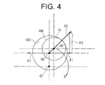
- the third axis O3 is eccentric to the first axis in a first direction (upper direction in the drawings), and the second axis O2 is eccentric to the first and third axes O1 and O3 in a second direction (upper-right direction in the drawings).
- the eccentric pin 16 revolves around the first axis O1 in a direction where the second axis O2 is located relative to the third axis O3 (clockwise direction in the drawings).
- the center of gravity C1 of the counterweight 17 is located on an extension of a straight line extending from the third axis O3 to the first axis O1.
- the scroll wall 5D of the fixed scroll 5 and the scroll wall 9B of the movable scroll 9 are engaged with each other with the distal ends of the scroll walls 5D and 9B in sliding contact with the their associated end plate 9A of the movable scroll 9 and the end plate 5A of the fixed scroll 5, respectively.
- the end plate 9A is formed in the front surface thereof with three or more recesses 10B (only one is shown in the drawings) and a ring 10C is loosely fitted in each recess 10B for receiving therein the distal ends of the respective pins 10A for rolling in contact with the inner peripheral surface of the ring 10C.
- the recess 10B, the ring 10C and the pin 10A cooperate to form an anti-rotation mechanism of the compressor for preventing the rotation of the movable scroll 9 on its own axis.
- each compression chamber 19 is defined by the base 5C, the scroll wall 5D, the end plate 9A and the scroll wall 9B.
- the end plate 9A cooperates with the shaft support 4 to form therebetween a backpressure chamber 20 that is located on the opposite side of the end plate 9A from the compression chambers 19 and faces the rear end portion of the drive shaft 13.
- the compressor has a suction region 21 that is defined by the shaft support 4, the side wall 5B of the fixed scroll 5 and the radially outermost portion of the movable scroll 9.
- the suction chamber 7 communicates with the suction region 21 through a suction passage 22 that is formed in the lower portion of the front housing 1.
- a stator 23 is fixedly mounted on the inner peripheral surface of the front housing 1, and a rotor 24 is secured to the drive shaft 13 at a position radially inward of the stator 23.
- the rotor 24, the stator 23 and the drive shaft 13 cooperate to form a motor mechanism of the compressor.
- the drive shaft 13 is rotatable integrally with the rotor 24 when the stator 23 is energized.
- the side wall of the front housing 1 has an inlet port 1C formed therethrough.
- the inlet port 1C is connected via a pipe to an evaporator that is further connected to an expansion valve and a condenser via a pipe in a refrigeration circuit of the vehicle air conditioner.
- low-pressure and low-temperature refrigerant gas in the refrigeration circuit is introduced through the inlet port 1C, the suction chamber 7 and the suction passage 22 into the suction region 21.
- the discharge chamber 8 is formed between the base 5C of the fixed scroll 5 and the rear housing 2.
- the base 5C has a discharge port 5E through which the radially innermost compression chamber 19 is connected to the discharge chamber 8.
- the discharge port 5E is closed by a discharge valve (not shown), the opening of which is restricted by a retainer 25 mounted to the rear end of the base 5C.
- the rear housing 2 is formed with an oil separation chamber 2A that extends vertically behind the discharge chamber 8.
- the oil separation chamber 2A is separated from the discharge chamber 8 by a partition wall 2B.
- the partition wall 2B is formed therethrough with a discharge hole 2C through which the oil separation chamber 2A communicates with the discharge chamber 8.
- an oil separator 26 is provided in the oil separation chamber 2A for separating lubricating oil contained in refrigerant gas.
- the oil separator 26 is of a generally cylindrical shape and fitted in the upper portion of the oil separation chamber 2A.
- Lubricating oil contained in the refrigerant gas introduced from the discharge chamber 8 through the discharge hole 2C into the oil separation chamber 2A is separated from the refrigerant gas by the oil separator 26 under the influence of centrifugal force.
- the separated oil is dropped into the bottom of the oil separation chamber 2A and stored therein.
- the part of the oil separation chamber 2A located above the oil separator 26 forms an outlet port 2D of the compressor that is connected through a pipe to
- the oil separation chamber 2A and the discharge chamber 8 are connected at the bottom thereof with each other through an oil hole 2E.
- the discharge chamber 8 is connected to the backpressure chamber 20 through a supply passage 27.
- the supply passage 27 is provided by a communication hole 27A and a slit 27B.
- the communication hole 27A extends through the side wall 5B of the fixed scroll 5.
- the slit 27B is formed through a plate 28 that is interposed between the shaft support 4 and the movable scroll 9.
- the slit 27B is connected to the communication passage 27A and extends circularly to the backpressure chamber 20. Part of high-pressure refrigerant gas in the discharge chamber 8, which contains lubricating oil, is delivered through the supply passage 27 into the backpressure chamber 20.
- the eccentric pin 16 when the drive shaft 13 of the motor mechanism is rotated, the eccentric pin 16 is revolved around the first axis O1 in R direction, as shown in Fig. 4 .
- the outer peripheral surface 16A of the eccentric pin 16 slides and rolls on the inner peripheral surface 18E of the inner ring 18C of the bearing 18.
- the inner ring 18C is rotated on the third axis O3 while revolving around the first axis O1, and the outer ring 18A is revolved around the first axis O1.
- the pin 10A slides and rolls on the inner peripheral surface of the ring 10C, and the ring 10C slides and rolls on the inner peripheral surface of the recess 10B.
- the movable scroll 9 is revolved around the first axis O1.
- the counterweight 17 serves to cancel the centrifugal force caused by the revolution of the movable scroll 9.
- Each compression chamber 19 between the scroll walls 5D and 9B of the fixed and movable scrolls 5 and 9 is moved inwardly while reducing its volume with the revolution of the movable scroll 9. Therefore, refrigerant gas introduced from the evaporator through the inlet port 1C, the suction chamber 7 and the suction passage 22 into the suction region 21 is compressed in the compression chamber 19.
- Refrigerant gas compressed to a predetermined discharge pressure is discharged through the discharge port 5E into the discharge chamber 8.
- the refrigerant gas is delivered through the discharge hole 2C into the oil separation chamber 2A where lubricating oil contained in the refrigerant gas is separated. Lubricating oil separated from the refrigerant gas is dropped from the oil separator 26 into the bottom of the oil separation chamber 2A and stored therein.
- the lubricating oil stored in the oil separation chamber 2A is then delivered along with a small amount of refrigerant gas through the supply passage 27 to the backpressure chamber 20.
- the refrigerant gas from which the lubricating oil has been separated is delivered through the oil separator 26 and the outlet port 2D into the condenser.
- rotational force F1 acts on the eccentric pin 16, as shown in Fig. 4 , contributing to the compression of refrigerant gas in the compression chambers 19.
- the eccentric pin 16 receives reaction force F1' that is directed in opposite direction to the rotational force F1.
- Driving force F2 which is directed in a direction from the third axis O3 to the second axis O2, acts on the eccentric pin 16.
- pressing force F3 which is the vector difference between the driving force F2 and the rotational force F1
- the compressor dispenses with a conventional bush, resulting in the reduction of the number of parts.
- the compressor according to the present invention allows reduced number of parts, as well as improving the performance of sealing between the fixed and movable scrolls 5 and 9.
- the compressor also provides an eccentric pin having a sufficient strength in a small-size compressor.
- the drive shaft 13, the eccentric pin 16 and the counterweight 17 are formed integrally in the present embodiment, which is advantageous in reduction of the number of parts of the compressor. This allows reduced weight and size of the compressor and makes it easier to mount the compressor in a vehicle.
- the eccentric pin 16 can be made with an increased diameter and, therefore, the flexibility of selecting material for the drive shaft 13 is enhanced, which makes it easier to design the compressor and reduces the manufacturing cost of the compressor.
- Fig. 5 shows the second embodiment of the present invention.
- same reference numerals are used for the common elements or components in the first and second embodiments, and the description of such elements or components for the second embodiment will be omitted.
- a component 30 including an eccentric pin 30A and a counterweight 30B is provided separately from a drive shaft 29 of the compressor.
- the component 30 is coupled to the drive shaft 29 by press fitting, so that the eccentric pin 30A and the counterweight 30B are integrated with the drive shaft 29. That is, the eccentric pin 30A and the counterweight 30B are integrally mounted on the drive shaft 29.
- scroll compressors of various specifications can be manufactured by increasing the number of kinds of component 30, which minimizes manufacturing cost increase while maintaining versatility of the drive shaft 29. Additionally, the second embodiment offers the advantages similar to those of the first embodiment.
- the bearing 18, which is provided by a roller bearing, may be replaced with a plane bearing.
- the present invention may be applied to a pump as well as to a compressor.
Landscapes
- Engineering & Computer Science (AREA)
- Mechanical Engineering (AREA)
- General Engineering & Computer Science (AREA)
- Rotary Pumps (AREA)
- Applications Or Details Of Rotary Compressors (AREA)
Abstract
A scroll-type fluid machine includes a mechanism for driving a movable scroll relative to a fixed scroll. The mechanism includes a drive shaft rotatable on a first axis, an eccentric pin and a bearing. The eccentric pin revolves around the first axis with the rotation of the drive shaft and has an outer peripheral surface centered on a second axis that is parallel to and eccentric to the first axis. The bearing is mounted to the movable scroll and has an inner peripheral surface centered on a third axis that is parallel to and eccentric to the first and second axes. The inner peripheral surface is in contact with the outer peripheral surface of the eccentric pin. Pressing force is applied to the bearing from the eccentric pin due to the arrangement of the first, second and third axes so as to press the movable scroll to the fixed scroll.
Description
- The present invention relates to a scroll-type fluid machine.
- Conventional scroll-type fluid machines are disclosed in, for example, Japanese Unexamined Utility Model Application Publication No.
57-204401 61-8403 - The drive mechanism disclosed in Japanese Unexamined Utility Model Application Publication No.
57-204401 - In the fluid machine with such drive mechanism, the eccentric pin revolves around the first axis with the rotation of the drive shaft on the first axis, and the movable scroll coupled to the eccentric pin through the bearing revolves around the first axis with the rotation on its own axis restricted by the anti-rotation mechanism. In the fluid machine, no bush is provided between the eccentric pin and the bearing, resulting in a reduced number of parts.
- The drive mechanism disclosed in Japanese Unexamined Patent Application Publication No.
61-8403 - In the fluid machine with such drive mechanism, the eccentric pin revolves around the first axis with the rotation of the drive shaft on the first axis, and the bush revolves around the first axis with the rotation about the second axis allowed. The movable scroll coupled to the bush through the bearing revolves around the first axis with the rotation on its own axis restricted by the anti-rotation mechanism. In this case, the bearing receives pressing force from the eccentric pin and the bush, which improves sealing between the fixed scroll and the movable scroll.
- However, neither of the above fluid machines allows reduced number of parts and improved sealing between the fixed and movable scrolls simultaneously.
- In the drive mechanism disclosed in Japanese Unexamined Patent Application Publication No.
61-8403 - The present invention is directed to providing a scroll-type fluid machine that allows reduced number of parts as well as improved sealing between scrolls and also provides an eccentric pin of sufficient strength in a small-size fluid machine.
- In accordance with an aspect of the present invention, a scroll-type fluid machine includes a fixed scroll and a movable scroll engaged with each other, an anti-rotation mechanism for preventing the rotation of the movable scroll on its own axis, and a drive mechanism for driving the movable scroll in orbital motion relative to the fixed scroll. The drive mechanism includes a drive shaft, an eccentric pin and a bearing. The drive shaft is rotatable on a first axis. The eccentric pin revolves around the first axis with the rotation of the drive shaft. The eccentric pin has an outer peripheral surface centered on a second axis that is parallel to and eccentric to the first axis. The bearing is mounted to the movable scroll. The bearing has an inner peripheral surface centered on a third axis that is parallel to and eccentric to the first and second axes, and the inner peripheral surface is in contact with the outer peripheral surface of the eccentric pin. Pressing force is applied to the bearing from the eccentric pin due to the arrangement of the first, second and third axes so as to press the movable scroll to the fixed scroll.
- Other aspects and advantages of the invention will become apparent from the following description, taken in conjunction with the accompanying drawings, illustrating by way of example the principles of the invention.
-
-
Fig. 1 is a longitudinal sectional view of a scroll compressor according to a first embodiment of the present invention; -
Fig. 2 is an enlarged fragmentary view of the compressor ofFig. 1 ; -
Fig. 3 is a fragmentary elevational view of a structure around an eccentric pin of the compressor ofFig. 1 ; -
Fig. 4 is a schematic diagram showing first, second and third axes in the compressor ofFig. 1 ; and -
Fig. 5 is a fragmentary sectional view of a scroll compressor according to a second embodiment of the present invention. - The following will describe the embodiments of the present invention with reference to the accompanying drawings.
-
Fig. 1 shows a scroll compressor according to the first embodiment of the present invention. It is noted that the right-hand side and the left-hand side as viewed inFig. 1 are the front side and the rear side of the scroll compressor, respectively, and that the upper and lower sides as viewed inFig. 1 are the upper and lower sides of the scroll compressor when installed in place, respectively. The scroll compressor (hereinafter referred to merely as compressor) is used, for example, in a vehicle air conditioner. The compressor has a cylindrical front housing 1 the opening of which is covered by a rear housing 2. The front housing 1 and the rear housing 2 cooperate to form a housing assembly 3 that accommodates therein ashaft support 4, afixed scroll 5 and amovable scroll 9. Thefixed scroll 5 is located behind theshaft support 4. The front housing 1 and the rear housing 2 are connected to each other by usingbolts 6 while keeping theshaft support 4 in contact with thefixed scroll 5. The compressor has asuction chamber 7 formed between the front housing 1 and theshaft support 4 and adischarge chamber 8 formed between thefixed scroll 5 and the rear housing 2. - The
shaft support 4 has a cylindricalmain body 4A and aflange 4B that extends radially outward from the rear end of themain body 4A. Themain body 4A has a shaft hole 4C formed therethrough. Theflange 4B is engaged with astep 1A that is formed in the inner peripheral surface of the front housing 1. Theshaft support 4 has three ormore pins 10A (only one is shown in the drawing) fixed to the rear end thereof for preventing rotation of themovable scroll 9 on its own axis, - The compressor has a
drive shaft 13 extending in the front housing 1 in longitudinal direction of the compressor. The front portion of thedrive shaft 13 is rotatably supported by abearing 11 that is mounted at the center of theend wall 1 B of the front housing 1. The rear end portion of thedrive shaft 13 is rotatably supported by abearing 12 that is mounted in themain body 4A of theshaft support 4. Thedrive shaft 13 is rotatable on a first axis O1. Aseal member 14 is mounted on theshaft support 4 and retained by a circlip 15 for sealing between theshaft support 4 and thedrive shaft 13. - The
drive shaft 13 has a cylindricaleccentric pin 16 formed at the rear end thereof. Referring toFigs. 2 through 4 , theeccentric pin 16 has an outerperipheral surface 16A centered on a second axis O2 that is parallel to and eccentric to the first axis O1. - The
drive shaft 13 has a sector-shaped counterweight 17 formed at the rear end thereof. Thedrive shaft 13, theeccentric pin 16 and thecounterweight 17 are formed integrally. - As shown in
Fig. 1 , thefixed scroll 5 includes anend plate 5A, aside wall 5B and ascroll wall 5D. Theend plate 5A cooperates with theside wall 5B to form a cylindrical base 5C of thefixed scroll 5. Thescroll wall 5D is located radially inward of theside wall 5B and projects forward from theend plate 5A. - The
movable scroll 9 is engaged with the fixedscroll 5. Themovable scroll 9 includes acircular end plate 9A and ascroll wall 9B projecting rearward from theend plate 9A. - As shown in
Fig. 2 , theend plate 9A of themovable scroll 9 is formed with a cylindrical boss 9C projecting forward. The boss 9C has an innerperipheral surface 9D centered on a third axis O3 that is parallel to and eccentric to the first and second axes O1 and O2. - A
bearing 18 is provided between theeccentric pin 16 and themovable scroll 9. Thebearing 18 includes anouter ring 18A,balls 18B, an inner ring 18C and a retainer (not shown). Thebearing 18 is press-fitted at the outerperipheral surface 18D of theouter ring 18A thereof in the boss 9C of themovable scroll 9. The inner ring 18C has an inner diameter that is larger than the outer diameter of theeccentric pin 16. Thebearing 18 is in line contact at the innerperipheral surface 18E of the inner ring 18C thereof with theeccentric pin 16 at the outerperipheral surface 16A thereof. The innerperipheral surface 18E of the inner ring 18C of thebearing 18 is centered on the third axis O3, and the inner ring 18C of thebearing 18 is rotatable on the third axis O3. - The
drive shaft 13, theeccentric pin 16 and thebearing 18 cooperate to form a drive mechanism of the compressor for driving themovable scroll 9 relative to the fixedscroll 5. As shown inFigs. 3 and4 , the third axis O3 is eccentric to the first axis in a first direction (upper direction in the drawings), and the second axis O2 is eccentric to the first and third axes O1 and O3 in a second direction (upper-right direction in the drawings). Theeccentric pin 16 revolves around the first axis O1 in a direction where the second axis O2 is located relative to the third axis O3 (clockwise direction in the drawings). The center of gravity C1 of thecounterweight 17 is located on an extension of a straight line extending from the third axis O3 to the first axis O1. - As shown in
Fig. 1 , thescroll wall 5D of the fixedscroll 5 and thescroll wall 9B of themovable scroll 9 are engaged with each other with the distal ends of thescroll walls end plate 9A of themovable scroll 9 and theend plate 5A of the fixedscroll 5, respectively. As shown inFig. 2 , theend plate 9A is formed in the front surface thereof with three ormore recesses 10B (only one is shown in the drawings) and a ring 10C is loosely fitted in eachrecess 10B for receiving therein the distal ends of therespective pins 10A for rolling in contact with the inner peripheral surface of the ring 10C. Therecess 10B, the ring 10C and thepin 10A cooperate to form an anti-rotation mechanism of the compressor for preventing the rotation of themovable scroll 9 on its own axis. - The fixed
scroll 5 cooperates with themovable scroll 9 to form therebetween a plurality ofcompression chambers 19. Specifically, eachcompression chamber 19 is defined by the base 5C, thescroll wall 5D, theend plate 9A and thescroll wall 9B. Theend plate 9A cooperates with theshaft support 4 to form therebetween abackpressure chamber 20 that is located on the opposite side of theend plate 9A from thecompression chambers 19 and faces the rear end portion of thedrive shaft 13. Further, the compressor has asuction region 21 that is defined by theshaft support 4, theside wall 5B of the fixedscroll 5 and the radially outermost portion of themovable scroll 9. - The
suction chamber 7 communicates with thesuction region 21 through asuction passage 22 that is formed in the lower portion of the front housing 1. In thesuction chamber 7, astator 23 is fixedly mounted on the inner peripheral surface of the front housing 1, and arotor 24 is secured to thedrive shaft 13 at a position radially inward of thestator 23. Therotor 24, thestator 23 and thedrive shaft 13 cooperate to form a motor mechanism of the compressor. Thedrive shaft 13 is rotatable integrally with therotor 24 when thestator 23 is energized. - The side wall of the front housing 1 has an inlet port 1C formed therethrough. Although not shown in the drawings, the inlet port 1C is connected via a pipe to an evaporator that is further connected to an expansion valve and a condenser via a pipe in a refrigeration circuit of the vehicle air conditioner. In operation of the compressor, low-pressure and low-temperature refrigerant gas in the refrigeration circuit is introduced through the inlet port 1C, the
suction chamber 7 and thesuction passage 22 into thesuction region 21. - The
discharge chamber 8 is formed between the base 5C of the fixedscroll 5 and the rear housing 2. The base 5C has adischarge port 5E through which the radiallyinnermost compression chamber 19 is connected to thedischarge chamber 8. Thedischarge port 5E is closed by a discharge valve (not shown), the opening of which is restricted by aretainer 25 mounted to the rear end of the base 5C. - The rear housing 2 is formed with an
oil separation chamber 2A that extends vertically behind thedischarge chamber 8. Theoil separation chamber 2A is separated from thedischarge chamber 8 by apartition wall 2B. Thepartition wall 2B is formed therethrough with a discharge hole 2C through which theoil separation chamber 2A communicates with thedischarge chamber 8. In theoil separation chamber 2A, anoil separator 26 is provided for separating lubricating oil contained in refrigerant gas. Theoil separator 26 is of a generally cylindrical shape and fitted in the upper portion of theoil separation chamber 2A. Lubricating oil contained in the refrigerant gas introduced from thedischarge chamber 8 through the discharge hole 2C into theoil separation chamber 2A is separated from the refrigerant gas by theoil separator 26 under the influence of centrifugal force. The separated oil is dropped into the bottom of theoil separation chamber 2A and stored therein. The part of theoil separation chamber 2A located above theoil separator 26 forms anoutlet port 2D of the compressor that is connected through a pipe to the condenser of the refrigeration circuit. - The
oil separation chamber 2A and thedischarge chamber 8 are connected at the bottom thereof with each other through anoil hole 2E. Thedischarge chamber 8 is connected to thebackpressure chamber 20 through asupply passage 27. Thesupply passage 27 is provided by acommunication hole 27A and aslit 27B. Thecommunication hole 27A extends through theside wall 5B of the fixedscroll 5. Theslit 27B is formed through aplate 28 that is interposed between theshaft support 4 and themovable scroll 9. Theslit 27B is connected to thecommunication passage 27A and extends circularly to thebackpressure chamber 20. Part of high-pressure refrigerant gas in thedischarge chamber 8, which contains lubricating oil, is delivered through thesupply passage 27 into thebackpressure chamber 20. - In the above-described compressor, when the
drive shaft 13 of the motor mechanism is rotated, theeccentric pin 16 is revolved around the first axis O1 in R direction, as shown inFig. 4 . The outerperipheral surface 16A of theeccentric pin 16 slides and rolls on the innerperipheral surface 18E of the inner ring 18C of thebearing 18. The inner ring 18C is rotated on the third axis O3 while revolving around the first axis O1, and theouter ring 18A is revolved around the first axis O1. Thepin 10A slides and rolls on the inner peripheral surface of the ring 10C, and the ring 10C slides and rolls on the inner peripheral surface of therecess 10B. As a result, themovable scroll 9 is revolved around the first axis O1. Thecounterweight 17 serves to cancel the centrifugal force caused by the revolution of themovable scroll 9. - Each
compression chamber 19 between thescroll walls movable scrolls movable scroll 9. Therefore, refrigerant gas introduced from the evaporator through the inlet port 1C, thesuction chamber 7 and thesuction passage 22 into thesuction region 21 is compressed in thecompression chamber 19. Refrigerant gas compressed to a predetermined discharge pressure is discharged through thedischarge port 5E into thedischarge chamber 8. The refrigerant gas is delivered through the discharge hole 2C into theoil separation chamber 2A where lubricating oil contained in the refrigerant gas is separated. Lubricating oil separated from the refrigerant gas is dropped from theoil separator 26 into the bottom of theoil separation chamber 2A and stored therein. The lubricating oil stored in theoil separation chamber 2A is then delivered along with a small amount of refrigerant gas through thesupply passage 27 to thebackpressure chamber 20. The refrigerant gas from which the lubricating oil has been separated is delivered through theoil separator 26 and theoutlet port 2D into the condenser. - While the
drive shaft 13 is being rotated, rotational force F1 acts on theeccentric pin 16, as shown inFig. 4 , contributing to the compression of refrigerant gas in thecompression chambers 19. Thus, theeccentric pin 16 receives reaction force F1' that is directed in opposite direction to the rotational force F1. Driving force F2, which is directed in a direction from the third axis O3 to the second axis O2, acts on theeccentric pin 16. In such a case, pressing force F3, which is the vector difference between the driving force F2 and the rotational force F1, is applied to the bearing 18 from theeccentric pin 16 so as to press themovable scroll 9 to the fixedscroll 5, which improves the sealing between the fixed andmovable scrolls - Furthermore, no provision of a bush between the
eccentric pin 16 and themovable scroll 9 allows theeccentric pin 16 to have a diameter that is large enough to ensure sufficient strength of theeccentric pin 16 in a small-size compressor. - As described above, the compressor according to the present invention allows reduced number of parts, as well as improving the performance of sealing between the fixed and
movable scrolls drive shaft 13, theeccentric pin 16 and thecounterweight 17 are formed integrally in the present embodiment, which is advantageous in reduction of the number of parts of the compressor. This allows reduced weight and size of the compressor and makes it easier to mount the compressor in a vehicle. - Further, no provision of a bush in the compressor increases the distance between the second and third axes O2 and O3 and permits more flexible designing of the compressor and the reduction of the accumulation of tolerance in assembled parts. The
eccentric pin 16 can be made with an increased diameter and, therefore, the flexibility of selecting material for thedrive shaft 13 is enhanced, which makes it easier to design the compressor and reduces the manufacturing cost of the compressor. -
Fig. 5 shows the second embodiment of the present invention. InFig. 5 , same reference numerals are used for the common elements or components in the first and second embodiments, and the description of such elements or components for the second embodiment will be omitted. In the second embodiment, acomponent 30 including aneccentric pin 30A and acounterweight 30B is provided separately from adrive shaft 29 of the compressor. Thecomponent 30 is coupled to thedrive shaft 29 by press fitting, so that theeccentric pin 30A and thecounterweight 30B are integrated with thedrive shaft 29. That is, theeccentric pin 30A and thecounterweight 30B are integrally mounted on thedrive shaft 29. - According to the second embodiment, scroll compressors of various specifications can be manufactured by increasing the number of kinds of
component 30, which minimizes manufacturing cost increase while maintaining versatility of thedrive shaft 29. Additionally, the second embodiment offers the advantages similar to those of the first embodiment. - The above embodiments may be modified in various ways as exemplified below.
- The
bearing 18, which is provided by a roller bearing, may be replaced with a plane bearing. - The present invention may be applied to a pump as well as to a compressor.
Claims (7)
- A scrail-type fluid machine, comprising:a fixed scroll (5) and a movable scroll (9) engaged with each other;an anti-rotation mechanism for preventing the rotation of the movable scroll (9) on its own axis; anda drive mechanism for driving the movable scroll (9) in orbital motion relative to the fixed scroll (5),the scroll-type fluid machine characterized by the drive mechanism including:a drive shaft (13) rotatable on a first axis (O1);an eccentric pin (16) revolving around the first axis (O1) with the rotation of the drive shaft (13), the eccentric pin (16) having an outer peripheral surface (16A) centered on a second axis (O2) that is parallel to and eccentric to the first axis (O1); anda bearing (18) mounted to the movable scroll (9), the bearing (18) having an inner peripheral surface (18E) centered on a third axis (O3) that is parallel to and eccentric to the first and second axes (O1, O2), the inner peripheral surface (18E) being in contact with the outer peripheral surface (16A) of the eccentric pin (16),wherein pressing force (F3) is applied to the bearing (18) from the eccentric pin (16) due to the arrangement of the first, second and third axes (O1, O2, O3) so as to press the movable scroll (9) to the fixed scroll (5).
- The scroll-type fluid machine according to claim 1, further comprising a counterweight (17) having center of gravity (C1) on an extension of a straight line extending from the third axis (O3) to the first axis (O1), the counterweight (17) being formed integrally with the drive shaft (13) and the eccentric pin (16).
- The scroll-type fluid machine according to claim 1, further comprising a counterweight (17) having center of gravity (C1) on an extension of a straight line extending from the third axis (O3) to the first axis (O1), wherein the eccentric pin (30A) and the counterweight (30B) are integrally mounted on the drive shaft (29).
- The scroll-type fluid machine according to any of the preceding claims, wherein the movable scroll (9) is formed with a cylindrical boss (9C) centered on the third axis (O3), and the bearing (18) is provided by a roller bearing mounted in the boss (9C).
- The scroll-type fluid machine according to any of claims 1 to 4, wherein rotational force (F1) for rotating the movable scroll (9) and driving force (F2) directed in a direction from the third axis (O3) to the second axis (O2) are generated by the rotation of the drive shaft (13), and the pressing force (F3) is the vector difference between the rotational force (F1) and the driving force (F2).
- The scroll-type fluid machine according to claim 5, wherein the scroll-type fluid machine is a compressor, and the rotational force (F1) serves to compress refrigerant gas.
- The scroll-type fluid machine according to any one of claims 1 through 6, wherein the bearing (18) includes an inner ring (18C) having an inner diameter that is larger than the outer diameter of the eccentric pin (16), the inner ring (18C) being in line contact with the outer peripheral surface (16A) of the eccentric pin (16).
Applications Claiming Priority (1)
| Application Number | Priority Date | Filing Date | Title |
|---|---|---|---|
| JP2009033436A JP2010190074A (en) | 2009-02-17 | 2009-02-17 | Scroll type fluid machine |
Publications (1)
| Publication Number | Publication Date |
|---|---|
| EP2218914A2 true EP2218914A2 (en) | 2010-08-18 |
Family
ID=41839350
Family Applications (1)
| Application Number | Title | Priority Date | Filing Date |
|---|---|---|---|
| EP10153580A Withdrawn EP2218914A2 (en) | 2009-02-17 | 2010-02-15 | Scroll-type fluid machine |
Country Status (3)
| Country | Link |
|---|---|
| US (1) | US20100209278A1 (en) |
| EP (1) | EP2218914A2 (en) |
| JP (1) | JP2010190074A (en) |
Cited By (4)
| Publication number | Priority date | Publication date | Assignee | Title |
|---|---|---|---|---|
| EP2913531A1 (en) * | 2014-02-28 | 2015-09-02 | Mitsubishi Heavy Industries, Ltd. | Scroll compressor with balance weight |
| DE102016118525B4 (en) | 2016-09-29 | 2019-09-19 | Hanon Systems | Apparatus for compressing a gaseous fluid |
| DE102017102645B4 (en) | 2017-02-10 | 2019-10-10 | Hanon Systems | Refrigerant Scroll Compressor for use inside a heat pump |
| EP3643920A1 (en) * | 2018-09-27 | 2020-04-29 | Lg Electronics Inc. | Motor operated compressor |
Families Citing this family (26)
| Publication number | Priority date | Publication date | Assignee | Title |
|---|---|---|---|---|
| US7988433B2 (en) | 2009-04-07 | 2011-08-02 | Emerson Climate Technologies, Inc. | Compressor having capacity modulation assembly |
| JP5692177B2 (en) * | 2012-07-19 | 2015-04-01 | 株式会社豊田自動織機 | Compressor |
| US9651043B2 (en) | 2012-11-15 | 2017-05-16 | Emerson Climate Technologies, Inc. | Compressor valve system and assembly |
| US9249802B2 (en) | 2012-11-15 | 2016-02-02 | Emerson Climate Technologies, Inc. | Compressor |
| US9765784B2 (en) | 2013-07-31 | 2017-09-19 | Trane International Inc. | Oldham coupling with enhanced key surface in a scroll compressor |
| JP6245937B2 (en) * | 2013-10-25 | 2017-12-13 | 株式会社ヴァレオジャパン | Electric scroll compressor |
| US20160025094A1 (en) * | 2014-07-28 | 2016-01-28 | Emerson Climate Technologies, Inc. | Compressor motor with center stator |
| KR102080622B1 (en) * | 2015-03-06 | 2020-02-25 | 한온시스템 주식회사 | Scroll compressor |
| US9790940B2 (en) | 2015-03-19 | 2017-10-17 | Emerson Climate Technologies, Inc. | Variable volume ratio compressor |
| US10598180B2 (en) | 2015-07-01 | 2020-03-24 | Emerson Climate Technologies, Inc. | Compressor with thermally-responsive injector |
| WO2017037778A1 (en) * | 2015-08-28 | 2017-03-09 | 株式会社日立産機システム | Scroll-type fluid machine and maintenance method for same |
| KR101681590B1 (en) * | 2015-09-09 | 2016-12-01 | 엘지전자 주식회사 | Scroll compressor |
| US10890186B2 (en) | 2016-09-08 | 2021-01-12 | Emerson Climate Technologies, Inc. | Compressor |
| US10801495B2 (en) | 2016-09-08 | 2020-10-13 | Emerson Climate Technologies, Inc. | Oil flow through the bearings of a scroll compressor |
| US10753352B2 (en) | 2017-02-07 | 2020-08-25 | Emerson Climate Technologies, Inc. | Compressor discharge valve assembly |
| US11022119B2 (en) | 2017-10-03 | 2021-06-01 | Emerson Climate Technologies, Inc. | Variable volume ratio compressor |
| US10962008B2 (en) | 2017-12-15 | 2021-03-30 | Emerson Climate Technologies, Inc. | Variable volume ratio compressor |
| US10995753B2 (en) | 2018-05-17 | 2021-05-04 | Emerson Climate Technologies, Inc. | Compressor having capacity modulation assembly |
| JP7462403B2 (en) * | 2019-11-26 | 2024-04-05 | サンデン株式会社 | Compressor |
| US11655813B2 (en) | 2021-07-29 | 2023-05-23 | Emerson Climate Technologies, Inc. | Compressor modulation system with multi-way valve |
| US12259163B2 (en) | 2022-06-01 | 2025-03-25 | Copeland Lp | Climate-control system with thermal storage |
| US11846287B1 (en) | 2022-08-11 | 2023-12-19 | Copeland Lp | Scroll compressor with center hub |
| US11965507B1 (en) | 2022-12-15 | 2024-04-23 | Copeland Lp | Compressor and valve assembly |
| US12416308B2 (en) | 2022-12-28 | 2025-09-16 | Copeland Lp | Compressor with shutdown assembly |
| US12173708B1 (en) | 2023-12-07 | 2024-12-24 | Copeland Lp | Heat pump systems with capacity modulation |
| US12163523B1 (en) | 2023-12-15 | 2024-12-10 | Copeland Lp | Compressor and valve assembly |
Citations (2)
| Publication number | Priority date | Publication date | Assignee | Title |
|---|---|---|---|---|
| JPS57204401U (en) | 1981-06-22 | 1982-12-25 | ||
| JPS618403A (en) | 1984-06-21 | 1986-01-16 | Daikin Ind Ltd | Scroll type hydraulic machine |
Family Cites Families (2)
| Publication number | Priority date | Publication date | Assignee | Title |
|---|---|---|---|---|
| JP3106737B2 (en) * | 1992-11-17 | 2000-11-06 | 株式会社豊田自動織機製作所 | Scroll compressor |
| JP3236144B2 (en) * | 1993-09-14 | 2001-12-10 | 株式会社デンソー | Compressor |
-
2009
- 2009-02-17 JP JP2009033436A patent/JP2010190074A/en active Pending
-
2010
- 2010-02-12 US US12/705,139 patent/US20100209278A1/en not_active Abandoned
- 2010-02-15 EP EP10153580A patent/EP2218914A2/en not_active Withdrawn
Patent Citations (2)
| Publication number | Priority date | Publication date | Assignee | Title |
|---|---|---|---|---|
| JPS57204401U (en) | 1981-06-22 | 1982-12-25 | ||
| JPS618403A (en) | 1984-06-21 | 1986-01-16 | Daikin Ind Ltd | Scroll type hydraulic machine |
Cited By (6)
| Publication number | Priority date | Publication date | Assignee | Title |
|---|---|---|---|---|
| EP2913531A1 (en) * | 2014-02-28 | 2015-09-02 | Mitsubishi Heavy Industries, Ltd. | Scroll compressor with balance weight |
| DE102016118525B4 (en) | 2016-09-29 | 2019-09-19 | Hanon Systems | Apparatus for compressing a gaseous fluid |
| EP3521625A4 (en) * | 2016-09-29 | 2020-05-20 | Hanon Systems | GAS FLUID COMPRESSION DEVICE |
| US11002272B2 (en) | 2016-09-29 | 2021-05-11 | Hanon Systems | Gaseous fluid compression device |
| DE102017102645B4 (en) | 2017-02-10 | 2019-10-10 | Hanon Systems | Refrigerant Scroll Compressor for use inside a heat pump |
| EP3643920A1 (en) * | 2018-09-27 | 2020-04-29 | Lg Electronics Inc. | Motor operated compressor |
Also Published As
| Publication number | Publication date |
|---|---|
| US20100209278A1 (en) | 2010-08-19 |
| JP2010190074A (en) | 2010-09-02 |
Similar Documents
| Publication | Publication Date | Title |
|---|---|---|
| US20100209278A1 (en) | Scroll-type fluid machine | |
| US7473083B2 (en) | Oil separating device for compressor | |
| US8202071B2 (en) | Motor-driven scroll type compressor | |
| EP1679441B1 (en) | Scroll compressor | |
| EP3418575B1 (en) | Compressor having integrated flow path structure | |
| JP7151470B2 (en) | electric compressor | |
| CN111749887B (en) | Scroll compressor | |
| CN112443485B (en) | Electric compressor | |
| EP3712435A2 (en) | Motor-operated compressor | |
| US8535029B2 (en) | Scroll type compressor having reinforced fixed scroll | |
| WO2009002428A1 (en) | Tandem compressor system and method | |
| US11053941B2 (en) | Motor-operated compressor | |
| US11976653B2 (en) | Scroll compressor with suppressed reduction of rotational moment | |
| EP3418572B1 (en) | Compressor having lubrication structure for thrust surface | |
| JP4306771B2 (en) | Compressor | |
| CN115126694B (en) | Electric compressor | |
| JP4888427B2 (en) | Compressor | |
| JPH05149274A (en) | Scroll type compressor | |
| JP7742582B2 (en) | Hermetic electric compressor | |
| JP7546419B2 (en) | Scroll Compressor | |
| EP3992461B1 (en) | Scroll compressor | |
| JP4301122B2 (en) | Scroll compressor | |
| JP2009079561A (en) | Scroll compressor | |
| JP4199135B2 (en) | Scroll compressor | |
| JP2008309150A (en) | Scroll compressor |
Legal Events
| Date | Code | Title | Description |
|---|---|---|---|
| PUAI | Public reference made under article 153(3) epc to a published international application that has entered the european phase |
Free format text: ORIGINAL CODE: 0009012 |
|
| 17P | Request for examination filed |
Effective date: 20100215 |
|
| AK | Designated contracting states |
Kind code of ref document: A2 Designated state(s): AT BE BG CH CY CZ DE DK EE ES FI FR GB GR HR HU IE IS IT LI LT LU LV MC MK MT NL NO PL PT RO SE SI SK SM TR |
|
| AX | Request for extension of the european patent |
Extension state: AL BA RS |
|
| STAA | Information on the status of an ep patent application or granted ep patent |
Free format text: STATUS: THE APPLICATION HAS BEEN WITHDRAWN |
|
| 18W | Application withdrawn |
Effective date: 20110719 |