EP2218832A2 - Acceleration control for vehicles having a loader arm - Google Patents
Acceleration control for vehicles having a loader arm Download PDFInfo
- Publication number
- EP2218832A2 EP2218832A2 EP10153166A EP10153166A EP2218832A2 EP 2218832 A2 EP2218832 A2 EP 2218832A2 EP 10153166 A EP10153166 A EP 10153166A EP 10153166 A EP10153166 A EP 10153166A EP 2218832 A2 EP2218832 A2 EP 2218832A2
- Authority
- EP
- European Patent Office
- Prior art keywords
- vehicle
- load
- stability
- gravity
- center
- Prior art date
- Legal status (The legal status is an assumption and is not a legal conclusion. Google has not performed a legal analysis and makes no representation as to the accuracy of the status listed.)
- Withdrawn
Links
- 230000001133 acceleration Effects 0.000 title claims abstract description 37
- 230000005484 gravity Effects 0.000 claims abstract description 57
- 230000003068 static effect Effects 0.000 claims abstract description 22
- 238000000034 method Methods 0.000 claims description 12
- 230000008859 change Effects 0.000 claims description 6
- 238000013459 approach Methods 0.000 claims description 2
- RLQWHDODQVOVKU-UHFFFAOYSA-N tetrapotassium;silicate Chemical compound [K+].[K+].[K+].[K+].[O-][Si]([O-])([O-])[O-] RLQWHDODQVOVKU-UHFFFAOYSA-N 0.000 description 30
- 230000000875 corresponding effect Effects 0.000 description 4
- 239000012530 fluid Substances 0.000 description 4
- 238000004891 communication Methods 0.000 description 2
- 230000001276 controlling effect Effects 0.000 description 2
- 230000003247 decreasing effect Effects 0.000 description 2
- 230000007246 mechanism Effects 0.000 description 2
- 230000004044 response Effects 0.000 description 2
- 239000000725 suspension Substances 0.000 description 2
- 230000009471 action Effects 0.000 description 1
- 230000005540 biological transmission Effects 0.000 description 1
- 238000002485 combustion reaction Methods 0.000 description 1
- 238000010276 construction Methods 0.000 description 1
- 230000002596 correlated effect Effects 0.000 description 1
- 238000010586 diagram Methods 0.000 description 1
- 210000005069 ears Anatomy 0.000 description 1
- -1 gravel Substances 0.000 description 1
- 230000002706 hydrostatic effect Effects 0.000 description 1
- 230000001788 irregular Effects 0.000 description 1
- 239000000463 material Substances 0.000 description 1
- 239000002184 metal Substances 0.000 description 1
- 238000012986 modification Methods 0.000 description 1
- 230000004048 modification Effects 0.000 description 1
- 238000012544 monitoring process Methods 0.000 description 1
- 239000013618 particulate matter Substances 0.000 description 1
- 230000008569 process Effects 0.000 description 1
- 230000005855 radiation Effects 0.000 description 1
- 239000004576 sand Substances 0.000 description 1
- 239000007787 solid Substances 0.000 description 1
- 230000000007 visual effect Effects 0.000 description 1
Images


Classifications
-
- E—FIXED CONSTRUCTIONS
- E02—HYDRAULIC ENGINEERING; FOUNDATIONS; SOIL SHIFTING
- E02F—DREDGING; SOIL-SHIFTING
- E02F9/00—Component parts of dredgers or soil-shifting machines, not restricted to one of the kinds covered by groups E02F3/00 - E02F7/00
- E02F9/20—Drives; Control devices
- E02F9/2025—Particular purposes of control systems not otherwise provided for
- E02F9/2029—Controlling the position of implements in function of its load, e.g. modifying the attitude of implements in accordance to vehicle speed
-
- B—PERFORMING OPERATIONS; TRANSPORTING
- B66—HOISTING; LIFTING; HAULING
- B66F—HOISTING, LIFTING, HAULING OR PUSHING, NOT OTHERWISE PROVIDED FOR, e.g. DEVICES WHICH APPLY A LIFTING OR PUSHING FORCE DIRECTLY TO THE SURFACE OF A LOAD
- B66F17/00—Safety devices, e.g. for limiting or indicating lifting force
- B66F17/003—Safety devices, e.g. for limiting or indicating lifting force for fork-lift trucks
-
- B—PERFORMING OPERATIONS; TRANSPORTING
- B66—HOISTING; LIFTING; HAULING
- B66F—HOISTING, LIFTING, HAULING OR PUSHING, NOT OTHERWISE PROVIDED FOR, e.g. DEVICES WHICH APPLY A LIFTING OR PUSHING FORCE DIRECTLY TO THE SURFACE OF A LOAD
- B66F9/00—Devices for lifting or lowering bulky or heavy goods for loading or unloading purposes
- B66F9/06—Devices for lifting or lowering bulky or heavy goods for loading or unloading purposes movable, with their loads, on wheels or the like, e.g. fork-lift trucks
- B66F9/075—Constructional features or details
- B66F9/0755—Position control; Position detectors
-
- E—FIXED CONSTRUCTIONS
- E02—HYDRAULIC ENGINEERING; FOUNDATIONS; SOIL SHIFTING
- E02F—DREDGING; SOIL-SHIFTING
- E02F3/00—Dredgers; Soil-shifting machines
- E02F3/04—Dredgers; Soil-shifting machines mechanically-driven
- E02F3/28—Dredgers; Soil-shifting machines mechanically-driven with digging tools mounted on a dipper- or bucket-arm, i.e. there is either one arm or a pair of arms, e.g. dippers, buckets
- E02F3/34—Dredgers; Soil-shifting machines mechanically-driven with digging tools mounted on a dipper- or bucket-arm, i.e. there is either one arm or a pair of arms, e.g. dippers, buckets with bucket-arms, i.e. a pair of arms, e.g. manufacturing processes, form, geometry, material of bucket-arms directly pivoted on the frames of tractors or self-propelled machines
- E02F3/3414—Dredgers; Soil-shifting machines mechanically-driven with digging tools mounted on a dipper- or bucket-arm, i.e. there is either one arm or a pair of arms, e.g. dippers, buckets with bucket-arms, i.e. a pair of arms, e.g. manufacturing processes, form, geometry, material of bucket-arms directly pivoted on the frames of tractors or self-propelled machines the arms being pivoted at the rear of the vehicle chassis, e.g. skid steer loader
-
- E—FIXED CONSTRUCTIONS
- E02—HYDRAULIC ENGINEERING; FOUNDATIONS; SOIL SHIFTING
- E02F—DREDGING; SOIL-SHIFTING
- E02F9/00—Component parts of dredgers or soil-shifting machines, not restricted to one of the kinds covered by groups E02F3/00 - E02F7/00
- E02F9/20—Drives; Control devices
- E02F9/2025—Particular purposes of control systems not otherwise provided for
- E02F9/2033—Limiting the movement of frames or implements, e.g. to avoid collision between implements and the cabin
-
- E—FIXED CONSTRUCTIONS
- E02—HYDRAULIC ENGINEERING; FOUNDATIONS; SOIL SHIFTING
- E02F—DREDGING; SOIL-SHIFTING
- E02F9/00—Component parts of dredgers or soil-shifting machines, not restricted to one of the kinds covered by groups E02F3/00 - E02F7/00
- E02F9/24—Safety devices, e.g. for preventing overload
-
- E—FIXED CONSTRUCTIONS
- E02—HYDRAULIC ENGINEERING; FOUNDATIONS; SOIL SHIFTING
- E02F—DREDGING; SOIL-SHIFTING
- E02F9/00—Component parts of dredgers or soil-shifting machines, not restricted to one of the kinds covered by groups E02F3/00 - E02F7/00
- E02F9/26—Indicating devices
- E02F9/264—Sensors and their calibration for indicating the position of the work tool
- E02F9/265—Sensors and their calibration for indicating the position of the work tool with follow-up actions (e.g. control signals sent to actuate the work tool)
Definitions
- the present invention is directed to electronic control systems of work vehicles. More particularly, it relates to electronically controlled drive systems for work vehicles having a loader arm, such as skid steer loaders, telescopic handlers, wheel loaders, backhoe loaders or forklift skid steer loaders.
- a loader arm such as skid steer loaders, telescopic handlers, wheel loaders, backhoe loaders or forklift skid steer loaders.
- Vehicles having a loader arm such as skid steer loaders, telescopic handlers, wheel loaders, backhoe loaders and forklifts, are a mainstay of construction work and industry. While the present invention will be described with regard to a skid steer loader, a forklift and a telescopic handler, it is applicable to any vehicle that has an implement to lift a load and is subject to tipping.
- Skid steer loaders commonly have a loader or lift arm that is pivotally coupled to the chassis of the vehicle to raise and lower at the operator's command.
- This arm typically has a bucket, blade or other implement attached to the end of the arm that is lifted and lowered thereby.
- a bucket is attached, and the skid steer vehicle is used to carry supplies or particulate matter such as gravel, sand, or dirt around the worksite.
- Skid steer loaders have a relatively compact wheelbase. They are loaded by filling a bucket and raising the bucket in the air above the operator's head. The loaded bucket is not disposed at the center of the vehicle with its weight evenly distributed overall four wheels, but is typically cantilevered outward away from the vehicle at the front wheels. In addition, a sprung skid steer loader can roll and pitch to a much greater degree than an unsprung skid steer. All of these factors combined could make a skid steer loader unstable and subject to tipping.
- a vehicle having a loader arm capable of carrying a load and having a stability polygon also has (a) a device for sensing the weight of the load and generating a signal indicative thereof, (b) a device for sensing the height of the load and generating a signal indicative thereof, and (c) an electronic controller.
- the electronic controller is coupled to the device for sensing weight and the device for sensing height, and is programmed (i) to dynamically calculate the static center of gravity of the combined vehicle and load based upon the signals received from the device for sensing weight and the device for sensing height, (ii) to calculate the acceleration necessary to cause the dynamic center of gravity of the combined vehicle and load to extend exterior of the stability polygon for the vehicle, and (iii) to generate a signal to limit the acceleration of the vehicle to less than the dynamically calculated acceleration necessary to cause the dynamic center of gravity of the combined vehicle and load to extend exterior of the stability polygon for the vehicle.
- a method is provided. Said method of controlling a vehicle having a loader arm capable of carrying a load and having a stability polygon.
- the method includes (a) receiving a signal representative of the weight of the load, (b) receiving a signal representative of the height of the load, (c) combining the signals representative of the weight and height of the load to dynamically calculate the static center of gravity of the combined vehicle and load, (d) dynamically calculating the acceleration necessary to cause the dynamic center of gravity of the combined vehicle and load to extend exterior of the stability polygon for the vehicle; and (e) generating a signal to limit the acceleration of the vehicle to less than the dynamically calculated acceleration necessary to cause the dynamic center of gravity of the combined vehicle and load to extend exterior of the stability polygon for the vehicle.
- the first embodiment described below is a skid steer loader having a differential drive system in which the wheels on each side of the vehicle can be driven independently of each other.
- the loader may include an electronic control system capable of electronically monitoring the skid steer loader's load, the height of that load, and of responsively derating or reducing the drive system's response to operator commands.
- the electronic control system combines these sensor signals and, based on dynamically, i.e., continuously, calculating whether to and how much to derate the drive system.
- a skid steer loader 100 having a chassis 102 to which four wheels 104 are coupled in fore-and-aft relation, two wheels on each side of the vehicle, each wheel being coupled to and driven by a corresponding hydraulic drive motor 106.
- a mechanical linkage in the form of two loader arms or lift arms 108 are pivotally coupled to the chassis 102 of the loader 100 at one end 110 of the arms.
- the other end 112 of the arms is pivotally connected to an implement (herein shown as a bucket 114) that performs useful work.
- a bucket 114 an implement that performs useful work.
- Only one arm 108 can be seen.
- the other arm 108 is mounted on the other side of the vehicle in the same position as the arm shown in Figure 1 .
- Two actuators here exemplified as hydraulic lift cylinders 116 are coupled to and between the arms 108 and the chassis 102 of the vehicle to lift the arms 108 with respect to the chassis 102.
- Two additional actuators here shown as a pair of hydraulic bucket cylinders 118 are similarly coupled to and between the bucket 114 and the loader arms 108 to pivot the bucket with respect to the loader arms.
- the actuators shown here are hydraulic cylinders, they may be electric, hydraulic or pneumatic actuators.
- the mechanical linkage, shown here as a pair of loader arms may be one or more loader arms in any combination of bars or mechanical links that is configured to lift or lower the implement.
- the implement, shown here as bucket 114 need not be a bucket, but may be any implement coupled to the end of the mechanical linkage to perform work.
- the vehicle is supported on four wheels, each of which is driven by a corresponding individual hydraulic motor. While this arrangement is preferred, other arrangements are also considered satisfactory, such as two motors, one for each side of the vehicle that are coupled to one or more wheels on each side of the vehicle. There may be six or eight wheels.
- the wheels may be pneumatic or solid.
- the wheels may be metal, rubber or plastic. Some or all may be driven.
- a track may extend around the wheels to form a tracked drive.
- the illustrated motors are hydraulic. In the alternative, they may be electrical or pneumatic.
- the motors may be directly coupled to the wheels they drive. They may also be indirectly coupled through shaft, gear, belt, chain and gearbox arrangements that extend between the motor and the wheel or wheels to which the motor is coupled.
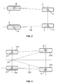
- the stability pyramid 120 for loader 100 may be determined by drawing an imaginary line between the support points A, B. C and D, i.e., where the supporting wheels 1, 2, 3 and 4 contact the ground. In the case of a vehicle with four independently hung wheels, the resulting quadrangle is the base of the machine's stability pyramid.
- the top point, or peak, of the stability pyramid 120 for loader 100 is located somewhere just above the operator's head.
- the peak of the stability pyramid 120 is positioned along a vertical line drawn through the static center of gravity of the combined vehicle and load.
- the height of the stability pyramid 120 depends on the height of the load, and fore and aft location of the stability pyramid 120 is determined by the position of the bucket 114.
- the stability pyramid 120 grows taller or shrinks, skews or becomes more vertical as the operator raises and lowers the bucket 114.
- the stability pyramid 120 is short and broad, making it relatively stable. Raising the bucket 114 elongates the stability pyramid 120, making it tall and narrow, and the loader 100 much more susceptible to tipping.
- the center of gravity rises as the load rises, and needs only to shift a short distance to get outside the narrow top of the imaginary stability pyramid 120 and cause the loader 100 to be much more susceptible to tipping, especially if the loader 100 is moving. Momentum multiplies the torque caused by turning or operating on sloping or rough surfaces, dramatically increasing the potential for tipping.
- forklift 310 comprises a main frame 312 supported at its rear end by a pair of wheels 314 and at its forward end by a pair of driving wheels 316.
- the forklift 310 is further provided with an internal combustion engine or battery-powered engine 320, connected through a suitable clutch and power transmission mechanism to the driving wheels 316 and with a steering wheel 322 and a suitable mechanism (not shown) joined to the rear wheels 314 to steer the forklift 310.
- Mast 324 is pivotally connected to the main frame 312 of the forklift 310 by a set of ears 326 and a pivot pin.
- the mast 324 may be mounted in a fixed upright position by a suitable bracing structure connected to the forward end of the forklift 310 or may be pivotally mounted on the forklift and connected by a pair of tilting rams 311 between the frame 312 and the mast 324. This pivoting action of the mast 324 assists in controlling the center of gravity of the forklift 310 as the load is lifted.
- a load-lifting carriage 330 is joined to the mast 324.
- the carriage supports a pair of forks 332 (only one being shown).
- the carriage 330 is guided in movement along the mast 324 by a set of rollers 334, 336, 338.
- the principles of the invention may be applied to any forklift truck body or frame.
- Figure 4 shows a plan view of the stability pyramid 120' for the forklift 310 of Figure 3 .
- the stability pyramid 120' on a counterbalanced forklift is independent of whether the vehicle has three wheels or four wheels.
- the steering axle pivots on its center pin, and that pivot pin becomes the third point forming the triangular base of the stability pyramid. Therefore, the base of the stability pyramid 120' is formed by the front support points A' and B' on the driving wheels 316 and the rear axle suspension point E' of the floating or swing axle.
- the forklift 310 will initially tip along the line B'-E' or A'-E'. If the floating axle comes into contact on one side against a stop or if its floating or swing movement is blocked, the tip E' of the stability triangle A'-B'-E' shifts to the support points C' and D' on the rear wheels 314. The tipping of the forklift in the transverse direction is then determined by the line B'-C' or A'-D'.
- the forklift 310 can tip forward about the axis A'-B', for example, if the load is sufficiently heavy and the forklift 310 is braked suddenly. If the forklift 310 is accelerated, dynamic center of gravity shifts to the rear and the forklift 310 tends to tip about axis C'-D'.
- the top point, or peak, of the stability pyramid 120' for forklift 310 is located somewhere just above the operator's head.
- the peak of the stability pyramid 120' is along a vertical line drawn through the static center of gravity of the combined vehicle and load.
- the height of the stability pyramid 120' depends on the height of the load, and fore and aft location of the stability pyramid 120' is determined by the position of the forks 332.
- the stability pyramid 120' elongates or contracts, skews or becomes more vertical as the operator manipulates the forks 332.
- the stability pyramid 120' is short and broad, making it relatively stable. Raising the forks 332 elongates the stability pyramid 120', making it tall and narrow, and the forklift 310 much more susceptible to tipping.
- the telescopic handler 400 includes two drive wheels 1" and 2" and two steering wheels 3" and 4" mounted on a single pivot rear axle 402. Therefore, the base of the stability pyramid 120" is a triangle A"-B"-E".
- a boom 404 is mounted on the frame of the telescopic handler 400 and supports a pair of pallet forks 406.
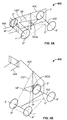
- the top point, or peak, of the stability pyramid 120" for telescopic handler 400 is located somewhere just above the operator's head. As shown in Figures 5A and 5B , the peak of the stability pyramid 120" is along a vertical line drawn through the static center of gravity SCG of the combined vehicle and load. The height of the stability pyramid 120" depends on the height of the load carried on the pallet forks 406, and fore and aft location of the stability pyramid 120" is determined by the position of the pallet forks 406.
- the stability pyramid 120" elongates or contracts as the operator manipulates the pallet forks 406.
- the stability pyramid 120" is short and broad, as shown in Figure 5A , making it relatively stable. Raising the pallet forks 406 elongates the stability pyramid 120", making it tall and narrow, as shown in Figure 5B , and the telescopic handler 400 much more susceptible to tipping.
- the static center of gravity SCG rises as the load rises.
- the vehicle will tip.
- the static center of gravity SCG is moved upwardly, the stability polygon is reduced and only a small shift in the center of gravity will cause the center of gravity to fall outside the stability polygon SP. Therefore, when the static center of gravity SCG is moved upwardly, the vehicle is becomes less unstable.
- the critical center of gravity that must stay within the stability polygon SP to prevent the vehicle from tipping over is the dynamic center of gravity DCG, which is calculated by adding the static center of gravity SCG and acceleration of the vehicle. Acceleration is caused by increasing the speed of the vehicle, decreasing the speed of the vehicle, or changing the direction of the travel of the vehicle.
- the acceleration of the vehicle is limited to less than the acceleration necessary to cause the dynamic center of gravity DCG of the combined vehicle and load to extend exterior of the stability polygon SP.
- the acceleration is limited by dynamically calculating the static center of gravity SCG based on the weight of the load carried by the vehicle implement and the height of the load, and dynamically calculating the acceleration necessary to cause the dynamic center of gravity DCG to extend exterior of the stability polygon SP.
- the rate of increase in the speed of the vehicle, the rate of decrease in the speed of the vehicle and the rate of change in the direction of the vehicle is limited to less than the dynamically calculated acceleration necessary to cause the dynamic center of gravity DCG to extend exterior of the stability polygon SP.
- an alarm may be mounted on the vehicle and be activated when the dynamic center of gravity DCG to approaches the edge of the stability polygon SP.
- the alarm may be either visual, such as a warning light, or audible, or a combination.
- the relative position of the vehicle with respect to horizontal affects both the size and shape of the base of the stability pyramid and the combined center of gravity of the vehicle and load. Therefore, the relative position of the vehicle with respect to horizontal may also be used in the calculation of the static center of gravity SCG and the acceleration necessary to cause the dynamic center of gravity DCG to extend exterior of the stability polygon SP.
- the relative position can be determined by an incline meter, a gyroscope or other means.
- the vehicle's electronic control system provides the ability to dynamically calculate the static center of gravity SCG and the acceleration necessary to cause the dynamic center of gravity DCG of the combined vehicle and load to extend exterior of the stability polygon SP for the vehicle.
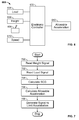
- Figure 6 illustrates the electronic control system in more detail.
- the electronic control system 600 may include an electronic controller 602 which includes one or more individual microcontrollers or microprocessors that may be networked over a serial communication bus such as a CAN bus (not shown). Other arrangements of microcontrollers and microprocessors may be used. There may be several sensors connected to the electronic controller 602 that provide the electronic controller with data indicating both vehicle load and the relative height of the load with respect to the base of the stability pyramid 120, 120', 120".
- a first of these sensors is load sensor 604.
- this sensor is a pressure sensor in fluid communication with the implement lift cylinder to generate a signal indicative of fluid pressure in the cylinder.
- the pressure in the hydraulic lift cylinders therefore indicates at least in part the load placed in the implement.
- the particular relationship of pressure to implement load depends, of course, upon the particular configuration and arrangement of the implement loader arms supporting the implement.
- the load sensor can be a pressure sensor coupled to a suspension cylinder.
- the load sensor can alternatively be a pressure sensor coupled to a pneumatic tire of the vehicle to sense tire pressure.
- a second of these sensors is a position or height sensor 606.
- height sensor 606 may be coupled to one of the lift cylinders to generate a signal indicative of lift cylinder extension.
- the sensor may be a rotary position sensor or a linear position sensor coupled to the moveable structure of the loader arms or any other portion of the linkage.
- the sensor may be a non-contact sensor such as a proximity sensor that generates a relative position signal that is based on capacitance or inductance.
- the sensor may be a radiation sensor such as an ultrasonic, radar, or laser sensor that measures distance.
- the sensor may be a flow sensor indicating fluid flow into or out of a hydraulic cylinder or other actuator that is related to the actuator position, such as a flow sensor coupled to the lift cylinder.
- the sensor may be a sensor responsive to remote signals correlated to height, such as such as a GPS or barometric pressure sensor.
- the electronic controller 602 may also be coupled to an operator input device 608 that is manipulable by the operator to signal a desired direction and speed of travel.
- Device 608 may be a joystick or a steering wheel and throttle arrangement or other arrangement.
- the joystick may generate two signals, a first signal indicating the deflection of the joystick along a fore-and-aft axis parallel to the fore-and-aft axis of the skid steer vehicle, and a second signal indicating the deflection along an orthogonal side-to-side axis parallel to the side-to-side axis of the skid steer vehicle.
- the operator indicates his desire to go straight forward or straight backward by moving the joystick straight forward or straight backward, respectively, with no deflection of the lever in a side-to-side direction.
- the operator indicates his desire to turn to the left or the right by moving the joystick side-to-side along the lateral axis of the joystick (i.e., to the right or to the left).
- the electronic controller 602 may also be coupled to a speed sensor 610 that generates a signal indicating the fore-and-aft velocity of the skid steer loader.
- Speed sensors may be wheel speed sensors disposed to sense the speed of wheels 1, 2, 3, 4, or hydrostatic motor speed sensors disposed to sense the speed of the wheel drive motors, or GPS receivers, lasers, or ground-sensing radars on the vehicle and disposed to sense the speed of the ground with respect to vehicle.
- the electronic control system 600 is configured to receive signals indicating the height of the load above the vehicle and the amount of load on the vehicle, and optionally, the speed of the vehicle, the direction and speed of travel desired by the operator.
- Electronic controller 602 combines the load and load height signals to dynamically calculate the static center of gravity SCG and dynamically calculate the acceleration necessary to cause the dynamic center of gravity of the combined vehicle and load to extend exterior of an edge of the stability polygon SP for the vehicle, and generates an allowable acceleration signal 612. If the commanded change in speed or direction of travel would cause the actual acceleration to exceed the acceleration necessary to cause the dynamic center of gravity of the combined vehicle and load to extend exterior of an edge of the stability polygon SP for the vehicle, the rate of change in speed or direction of travel will be reduced or limited.
- the static center of gravity SCG may be determined by measuring the weight on each tire or the weight on the front axle and the rear axle in combination with the incline or relative position of the vehicle, the loader arm position, the weight of the vehicle and the weight of the load. The static center of gravity SCG may then be calculated as known in the art.
- FIG. 7 illustrates the process performed by electronic controller 602 when it responds to operator manipulation of the operator input device 608.
- controller 602 reads the height signal generated by height sensor 606 that indicates the height of the vehicle load. Controller 602 saves the height signal for use in later computations.
- controller 602 reads the load signal generated by load sensor 604 that varies with the load applied by the implement coupled to the loader arms. Controller 602 saves this signal for use in further computations.
- controller 602 dynamically calculates the static center of gravity SCG.
- controller 602 dynamically calculates the acceleration necessary to cause the dynamic center of gravity DCG of the combined vehicle and load to extend exterior of the stability polygon SP for the vehicle.
- controller 602 generates a signal to limit the acceleration of the vehicle to less than the dynamically calculated acceleration necessary to cause the dynamic center of gravity of the combined vehicle and load to extend exterior of an edge of the stability polygon for the vehicle. If the particular vehicle operating conditions cause the dynamic center of gravity of the combined vehicle and load to extend exterior of the stability polygon for the vehicle, the acceleration is limited by controller 602.
- Limiting the acceleration of the vehicle may include controller 602 reading the position signal generated by operator input device 608 that indicates the position of the operator input device 608. Whether input device 608 is a joystick, multiple levers or some similar device, the input device generates a signal defining a commanded speed and direction and degree of turning of the vehicle. Controller 602 may also read the speed sensor signal 610 that is indicative of the speed of the vehicle to determine the acceleration that would occur in response to a commanded change in direction of travel of the vehicle.
Landscapes
- Engineering & Computer Science (AREA)
- Structural Engineering (AREA)
- Civil Engineering (AREA)
- Mining & Mineral Resources (AREA)
- General Engineering & Computer Science (AREA)
- Mechanical Engineering (AREA)
- Life Sciences & Earth Sciences (AREA)
- Geology (AREA)
- Transportation (AREA)
- Forklifts And Lifting Vehicles (AREA)
- Operation Control Of Excavators (AREA)
- Regulating Braking Force (AREA)
Abstract
Description
- The present invention is directed to electronic control systems of work vehicles. More particularly, it relates to electronically controlled drive systems for work vehicles having a loader arm, such as skid steer loaders, telescopic handlers, wheel loaders, backhoe loaders or forklift skid steer loaders.
- Vehicles having a loader arm, such as skid steer loaders, telescopic handlers, wheel loaders, backhoe loaders and forklifts, are a mainstay of construction work and industry. While the present invention will be described with regard to a skid steer loader, a forklift and a telescopic handler, it is applicable to any vehicle that has an implement to lift a load and is subject to tipping.
- Skid steer loaders commonly have a loader or lift arm that is pivotally coupled to the chassis of the vehicle to raise and lower at the operator's command. This arm typically has a bucket, blade or other implement attached to the end of the arm that is lifted and lowered thereby. Perhaps most commonly, a bucket is attached, and the skid steer vehicle is used to carry supplies or particulate matter such as gravel, sand, or dirt around the worksite.
- One of the disadvantages of traditional skid steer vehicles is their potential lack of stability when a loaded implement is raised, particularly when the load is extremely heavy. Such a condition leads to instability and potential tipping of the vehicle off its wheels. This is particularly true when the vehicle is accelerated, i.e., the rate of speed of the vehicle is increased, the rate of speed of the vehicle is decreased, the direction of travel is changed, or any combination. The instability problem is exacerbated when the vehicle travels up or down an incline, or over irregular terrain.
- Skid steer loaders have a relatively compact wheelbase. They are loaded by filling a bucket and raising the bucket in the air above the operator's head. The loaded bucket is not disposed at the center of the vehicle with its weight evenly distributed overall four wheels, but is typically cantilevered outward away from the vehicle at the front wheels. In addition, a sprung skid steer loader can roll and pitch to a much greater degree than an unsprung skid steer. All of these factors combined could make a skid steer loader unstable and subject to tipping.
- Other features and advantages of the present invention will be apparent from the following more detailed description of the preferred embodiment, taken in conjunction with the accompanying drawings which illustrate, by way of example, the principles of the invention.
- According to a first aspect of the present invention a vehicle according to
claim 1 is provided.A vehicle having a loader arm capable of carrying a load and having a stability polygon also has (a) a device for sensing the weight of the load and generating a signal indicative thereof, (b) a device for sensing the height of the load and generating a signal indicative thereof, and (c) an electronic controller. The electronic controller is coupled to the device for sensing weight and the device for sensing height, and is programmed (i) to dynamically calculate the static center of gravity of the combined vehicle and load based upon the signals received from the device for sensing weight and the device for sensing height, (ii) to calculate the acceleration necessary to cause the dynamic center of gravity of the combined vehicle and load to extend exterior of the stability polygon for the vehicle, and (iii) to generate a signal to limit the acceleration of the vehicle to less than the dynamically calculated acceleration necessary to cause the dynamic center of gravity of the combined vehicle and load to extend exterior of the stability polygon for the vehicle. - According to a second aspect of the invention a method according to claim 8 is provided. Said method of controlling a vehicle having a loader arm capable of carrying a load and having a stability polygon. The method includes (a) receiving a signal representative of the weight of the load, (b) receiving a signal representative of the height of the load, (c) combining the signals representative of the weight and height of the load to dynamically calculate the static center of gravity of the combined vehicle and load, (d) dynamically calculating the acceleration necessary to cause the dynamic center of gravity of the combined vehicle and load to extend exterior of the stability polygon for the vehicle; and (e) generating a signal to limit the acceleration of the vehicle to less than the dynamically calculated acceleration necessary to cause the dynamic center of gravity of the combined vehicle and load to extend exterior of the stability polygon for the vehicle.
- The invention will now be described in further detail, by way of example, with reference to the accompanying drawings, in which:
-
Figure 1 is a side view of a skid steer loader in accordance with the present invention; -
Figure 2 is a schematic illustration of a stability region, quadrangle or polygon of the skid steer loader ofFigure 1 ; -
Figure 3 is a side view of a forklift in accordance with the present invention; -
Figure 4 is a schematic illustration of a stability region, triangle or polygon of the forklift ofFigure 3 ; -
Figures 5A and 5B are schematic illustrations showing relationships between a stability polygon of a telescopic handler and increasing boom height; -
Figure 6 is a schematic diagram of an electronic control system corresponding to a stability polygon for a vehicle; -
Figure 7 is a flow chart corresponding to a stability polygon of a vehicle. - In the drawings, like reference numerals refer to like parts throughout the several views.
- While the invention has been described with reference to a number of embodiments, it will be understood by those skilled in the art that various changes may be made and equivalents may be substituted for elements thereof without departing from the scope of the invention. In addition, many modifications may be made to adapt a particular situation or material to the teachings of the invention without departing from the essential scope thereof. Therefore, it is intended that the invention not be limited to the particular embodiments disclosed as the best mode contemplated for carrying out this invention, but that the invention will include all embodiments falling within the scope of the appended claims.
- The first embodiment described below is a skid steer loader having a differential drive system in which the wheels on each side of the vehicle can be driven independently of each other. The loader may include an electronic control system capable of electronically monitoring the skid steer loader's load, the height of that load, and of responsively derating or reducing the drive system's response to operator commands. The electronic control system combines these sensor signals and, based on dynamically, i.e., continuously, calculating whether to and how much to derate the drive system.
- Referring to
Figure 1 , askid steer loader 100 is illustrated having achassis 102 to which fourwheels 104 are coupled in fore-and-aft relation, two wheels on each side of the vehicle, each wheel being coupled to and driven by a correspondinghydraulic drive motor 106. A mechanical linkage in the form of two loader arms orlift arms 108 are pivotally coupled to thechassis 102 of theloader 100 at oneend 110 of the arms. Theother end 112 of the arms is pivotally connected to an implement (herein shown as a bucket 114) that performs useful work. In the side view ofFigure 1 , only onearm 108 can be seen. Theother arm 108 is mounted on the other side of the vehicle in the same position as the arm shown inFigure 1 . - Two actuators, here exemplified as
hydraulic lift cylinders 116 are coupled to and between thearms 108 and thechassis 102 of the vehicle to lift thearms 108 with respect to thechassis 102. Two additional actuators, here shown as a pair ofhydraulic bucket cylinders 118 are similarly coupled to and between thebucket 114 and theloader arms 108 to pivot the bucket with respect to the loader arms. - While the actuators shown here are hydraulic cylinders, they may be electric, hydraulic or pneumatic actuators. The mechanical linkage, shown here as a pair of loader arms, may be one or more loader arms in any combination of bars or mechanical links that is configured to lift or lower the implement. The implement, shown here as
bucket 114, need not be a bucket, but may be any implement coupled to the end of the mechanical linkage to perform work. - In
Figure 1 the vehicle is supported on four wheels, each of which is driven by a corresponding individual hydraulic motor. While this arrangement is preferred, other arrangements are also considered satisfactory, such as two motors, one for each side of the vehicle that are coupled to one or more wheels on each side of the vehicle. There may be six or eight wheels. The wheels may be pneumatic or solid. The wheels may be metal, rubber or plastic. Some or all may be driven. A track may extend around the wheels to form a tracked drive. - In one embodiment, the illustrated motors are hydraulic. In the alternative, they may be electrical or pneumatic. The motors may be directly coupled to the wheels they drive. They may also be indirectly coupled through shaft, gear, belt, chain and gearbox arrangements that extend between the motor and the wheel or wheels to which the motor is coupled.
- The concept of a vehicle's "stability pyramid", which is a key to keeping the vehicle upright and operating safely is now disclosed. As long as the center of gravity of the combined vehicle and load is kept inside its imaginary stability pyramid, there is reduced risk of the vehicle tipping over. As shown in
Figure 2 , thestability pyramid 120 forloader 100 may be determined by drawing an imaginary line between the support points A, B. C and D, i.e., where the supportingwheels - In one embodiment, the top point, or peak, of the
stability pyramid 120 forloader 100 is located somewhere just above the operator's head. The peak of thestability pyramid 120 is positioned along a vertical line drawn through the static center of gravity of the combined vehicle and load. The height of thestability pyramid 120 depends on the height of the load, and fore and aft location of thestability pyramid 120 is determined by the position of thebucket 114. - The
stability pyramid 120 grows taller or shrinks, skews or becomes more vertical as the operator raises and lowers thebucket 114. When thebucket 114 is maintained in a position near the wheel operating surface, thestability pyramid 120 is short and broad, making it relatively stable. Raising thebucket 114 elongates thestability pyramid 120, making it tall and narrow, and theloader 100 much more susceptible to tipping. - The center of gravity rises as the load rises, and needs only to shift a short distance to get outside the narrow top of the
imaginary stability pyramid 120 and cause theloader 100 to be much more susceptible to tipping, especially if theloader 100 is moving. Momentum multiplies the torque caused by turning or operating on sloping or rough surfaces, dramatically increasing the potential for tipping. - Referring to
Figure 3 ,forklift 310 comprises amain frame 312 supported at its rear end by a pair ofwheels 314 and at its forward end by a pair of drivingwheels 316. Theforklift 310 is further provided with an internal combustion engine or battery-poweredengine 320, connected through a suitable clutch and power transmission mechanism to the drivingwheels 316 and with asteering wheel 322 and a suitable mechanism (not shown) joined to therear wheels 314 to steer theforklift 310. -
Mast 324 is pivotally connected to themain frame 312 of theforklift 310 by a set ofears 326 and a pivot pin. Themast 324 may be mounted in a fixed upright position by a suitable bracing structure connected to the forward end of theforklift 310 or may be pivotally mounted on the forklift and connected by a pair of tiltingrams 311 between theframe 312 and themast 324. This pivoting action of themast 324 assists in controlling the center of gravity of theforklift 310 as the load is lifted. - A load-lifting
carriage 330 is joined to themast 324. The carriage supports a pair of forks 332 (only one being shown). Thecarriage 330 is guided in movement along themast 324 by a set ofrollers -
Figure 4 shows a plan view of the stability pyramid 120' for theforklift 310 ofFigure 3 . The stability pyramid 120' on a counterbalanced forklift is independent of whether the vehicle has three wheels or four wheels. At first glance it would seem that the stability pyramid of a four-wheeled lift truck would have a rectangular or quadrangle base instead of a triangle, but that is not the case. The steering axle pivots on its center pin, and that pivot pin becomes the third point forming the triangular base of the stability pyramid. Therefore, the base of the stability pyramid 120' is formed by the front support points A' and B' on the drivingwheels 316 and the rear axle suspension point E' of the floating or swing axle. - In the transverse direction, the
forklift 310 will initially tip along the line B'-E' or A'-E'. If the floating axle comes into contact on one side against a stop or if its floating or swing movement is blocked, the tip E' of the stability triangle A'-B'-E' shifts to the support points C' and D' on therear wheels 314. The tipping of the forklift in the transverse direction is then determined by the line B'-C' or A'-D'. - In the longitudinal direction, the
forklift 310 can tip forward about the axis A'-B', for example, if the load is sufficiently heavy and theforklift 310 is braked suddenly. If theforklift 310 is accelerated, dynamic center of gravity shifts to the rear and theforklift 310 tends to tip about axis C'-D'. - As shown in
Figure 3 , the top point, or peak, of the stability pyramid 120' forforklift 310 is located somewhere just above the operator's head. The peak of the stability pyramid 120' is along a vertical line drawn through the static center of gravity of the combined vehicle and load. The height of the stability pyramid 120' depends on the height of the load, and fore and aft location of the stability pyramid 120' is determined by the position of theforks 332. - The stability pyramid 120' elongates or contracts, skews or becomes more vertical as the operator manipulates the
forks 332. When theforks 332 are maintained in a position near the wheel operation surface, the stability pyramid 120' is short and broad, making it relatively stable. Raising theforks 332 elongates the stability pyramid 120', making it tall and narrow, and theforklift 310 much more susceptible to tipping. - The center of gravity rises as the load rises, and needs only to shift a short distance to get outside the narrow top of the
imaginary stability pyramid 120, 120' and cause theloader 100 orforklift 310 to be much more susceptible to tipping, especially if theloader 100 orforklift 310 is moving. Shrinking of the stability polygon is more clearly shown inFigures 5A and 5B , which schematically illustrates atelescopic handler 400. - The
telescopic handler 400 includes twodrive wheels 1" and 2" and twosteering wheels 3" and 4" mounted on a single pivotrear axle 402. Therefore, the base of thestability pyramid 120" is a triangle A"-B"-E". Aboom 404 is mounted on the frame of thetelescopic handler 400 and supports a pair ofpallet forks 406. - As with the previous vehicles, the top point, or peak, of the
stability pyramid 120" fortelescopic handler 400 is located somewhere just above the operator's head. As shown inFigures 5A and 5B , the peak of thestability pyramid 120" is along a vertical line drawn through the static center of gravity SCG of the combined vehicle and load. The height of thestability pyramid 120" depends on the height of the load carried on thepallet forks 406, and fore and aft location of thestability pyramid 120" is determined by the position of thepallet forks 406. - Comparing
Figures 5A and 5B , thestability pyramid 120" elongates or contracts as the operator manipulates thepallet forks 406. When thepallet forks 406 are maintained in a position near the wheel operating surface, thestability pyramid 120" is short and broad, as shown inFigure 5A , making it relatively stable. Raising thepallet forks 406 elongates thestability pyramid 120", making it tall and narrow, as shown inFigure 5B , and thetelescopic handler 400 much more susceptible to tipping. - The static center of gravity SCG rises as the load rises. When the center of gravity falls outside the stability polygon SP defined by the horizontal cross-section of the
stability pyramid 120" containing the static center of gravity SCG, the vehicle will tip. As the static center of gravity SCG is moved upwardly, the stability polygon is reduced and only a small shift in the center of gravity will cause the center of gravity to fall outside the stability polygon SP. Therefore, when the static center of gravity SCG is moved upwardly, the vehicle is becomes less unstable. - The critical center of gravity that must stay within the stability polygon SP to prevent the vehicle from tipping over is the dynamic center of gravity DCG, which is calculated by adding the static center of gravity SCG and acceleration of the vehicle. Acceleration is caused by increasing the speed of the vehicle, decreasing the speed of the vehicle, or changing the direction of the travel of the vehicle.
- To deter the vehicle from tipping, the acceleration of the vehicle is limited to less than the acceleration necessary to cause the dynamic center of gravity DCG of the combined vehicle and load to extend exterior of the stability polygon SP. The acceleration is limited by dynamically calculating the static center of gravity SCG based on the weight of the load carried by the vehicle implement and the height of the load, and dynamically calculating the acceleration necessary to cause the dynamic center of gravity DCG to extend exterior of the stability polygon SP. The rate of increase in the speed of the vehicle, the rate of decrease in the speed of the vehicle and the rate of change in the direction of the vehicle is limited to less than the dynamically calculated acceleration necessary to cause the dynamic center of gravity DCG to extend exterior of the stability polygon SP.
- A predetermined tolerance or buffer between an acceptable reading and the actual stability polygon may be incorporated into the calculation. Therefore, the phrase "extend exterior of the stability polygon for the vehicle" is intended to mean "extend into the buffer or tolerance of the calculated stability polygon".
- As a further precaution, an alarm may be mounted on the vehicle and be activated when the dynamic center of gravity DCG to approaches the edge of the stability polygon SP. The alarm may be either visual, such as a warning light, or audible, or a combination.
- The relative position of the vehicle with respect to horizontal affects both the size and shape of the base of the stability pyramid and the combined center of gravity of the vehicle and load. Therefore, the relative position of the vehicle with respect to horizontal may also be used in the calculation of the static center of gravity SCG and the acceleration necessary to cause the dynamic center of gravity DCG to extend exterior of the stability polygon SP. The relative position can be determined by an incline meter, a gyroscope or other means.
- The vehicle's electronic control system provides the ability to dynamically calculate the static center of gravity SCG and the acceleration necessary to cause the dynamic center of gravity DCG of the combined vehicle and load to extend exterior of the stability polygon SP for the vehicle.
Figure 6 illustrates the electronic control system in more detail. - The
electronic control system 600 may include anelectronic controller 602 which includes one or more individual microcontrollers or microprocessors that may be networked over a serial communication bus such as a CAN bus (not shown). Other arrangements of microcontrollers and microprocessors may be used. There may be several sensors connected to theelectronic controller 602 that provide the electronic controller with data indicating both vehicle load and the relative height of the load with respect to the base of thestability pyramid - A first of these sensors is
load sensor 604. In one embodiment, this sensor is a pressure sensor in fluid communication with the implement lift cylinder to generate a signal indicative of fluid pressure in the cylinder. As the load increases in the implement, the hydraulic fluid pressure required to lift the implement increases. The pressure in the hydraulic lift cylinders therefore indicates at least in part the load placed in the implement. The particular relationship of pressure to implement load depends, of course, upon the particular configuration and arrangement of the implement loader arms supporting the implement. In an alternative embodiment, the load sensor can be a pressure sensor coupled to a suspension cylinder. The load sensor can alternatively be a pressure sensor coupled to a pneumatic tire of the vehicle to sense tire pressure. - A second of these sensors is a position or
height sensor 606. In one embodiment,height sensor 606 may be coupled to one of the lift cylinders to generate a signal indicative of lift cylinder extension. The sensor may be a rotary position sensor or a linear position sensor coupled to the moveable structure of the loader arms or any other portion of the linkage. The sensor may be a non-contact sensor such as a proximity sensor that generates a relative position signal that is based on capacitance or inductance. The sensor may be a radiation sensor such as an ultrasonic, radar, or laser sensor that measures distance. The sensor may be a flow sensor indicating fluid flow into or out of a hydraulic cylinder or other actuator that is related to the actuator position, such as a flow sensor coupled to the lift cylinder. Alternately, the sensor may be a sensor responsive to remote signals correlated to height, such as such as a GPS or barometric pressure sensor. - The
electronic controller 602 may also be coupled to anoperator input device 608 that is manipulable by the operator to signal a desired direction and speed of travel.Device 608 may be a joystick or a steering wheel and throttle arrangement or other arrangement. The joystick may generate two signals, a first signal indicating the deflection of the joystick along a fore-and-aft axis parallel to the fore-and-aft axis of the skid steer vehicle, and a second signal indicating the deflection along an orthogonal side-to-side axis parallel to the side-to-side axis of the skid steer vehicle. - Generally speaking, the operator indicates his desire to go straight forward or straight backward by moving the joystick straight forward or straight backward, respectively, with no deflection of the lever in a side-to-side direction. The operator indicates his desire to turn to the left or the right by moving the joystick side-to-side along the lateral axis of the joystick (i.e., to the right or to the left).
- The
electronic controller 602 may also be coupled to aspeed sensor 610 that generates a signal indicating the fore-and-aft velocity of the skid steer loader. Speed sensors may be wheel speed sensors disposed to sense the speed ofwheels - The
electronic control system 600 is configured to receive signals indicating the height of the load above the vehicle and the amount of load on the vehicle, and optionally, the speed of the vehicle, the direction and speed of travel desired by the operator.Electronic controller 602 combines the load and load height signals to dynamically calculate the static center of gravity SCG and dynamically calculate the acceleration necessary to cause the dynamic center of gravity of the combined vehicle and load to extend exterior of an edge of the stability polygon SP for the vehicle, and generates anallowable acceleration signal 612. If the commanded change in speed or direction of travel would cause the actual acceleration to exceed the acceleration necessary to cause the dynamic center of gravity of the combined vehicle and load to extend exterior of an edge of the stability polygon SP for the vehicle, the rate of change in speed or direction of travel will be reduced or limited. - In another embodiment, the static center of gravity SCG may be determined by measuring the weight on each tire or the weight on the front axle and the rear axle in combination with the incline or relative position of the vehicle, the loader arm position, the weight of the vehicle and the weight of the load. The static center of gravity SCG may then be calculated as known in the art.
-
Figure 7 illustrates the process performed byelectronic controller 602 when it responds to operator manipulation of theoperator input device 608. Inblock 700,controller 602 reads the height signal generated byheight sensor 606 that indicates the height of the vehicle load.Controller 602 saves the height signal for use in later computations. - In
block 702,controller 602 reads the load signal generated byload sensor 604 that varies with the load applied by the implement coupled to the loader arms.Controller 602 saves this signal for use in further computations. - In
block 704,controller 602 dynamically calculates the static center of gravity SCG. Inblock 706,controller 602 dynamically calculates the acceleration necessary to cause the dynamic center of gravity DCG of the combined vehicle and load to extend exterior of the stability polygon SP for the vehicle. - In
block 708,controller 602 generates a signal to limit the acceleration of the vehicle to less than the dynamically calculated acceleration necessary to cause the dynamic center of gravity of the combined vehicle and load to extend exterior of an edge of the stability polygon for the vehicle. If the particular vehicle operating conditions cause the dynamic center of gravity of the combined vehicle and load to extend exterior of the stability polygon for the vehicle, the acceleration is limited bycontroller 602. - Limiting the acceleration of the vehicle may include
controller 602 reading the position signal generated byoperator input device 608 that indicates the position of theoperator input device 608. Whetherinput device 608 is a joystick, multiple levers or some similar device, the input device generates a signal defining a commanded speed and direction and degree of turning of the vehicle.Controller 602 may also read thespeed sensor signal 610 that is indicative of the speed of the vehicle to determine the acceleration that would occur in response to a commanded change in direction of travel of the vehicle.
Claims (14)
- A vehicle (100, 310, 400) having a loader arm (108, 324, 404) capable of carrying a load and having a stability polygon (120, 120', 120") comprising:- a device for sensing the weight of said load (604) and generating a signal indicative thereof;- a device for sensing the height of said load (606) and generating a signal indicative thereof;- an electronic controller (602) coupled to said device for sensing the weight (604) and height (606) of the load, andcharacterized in that said electronic controller (602) is programmed to dynamically calculate the static center of gravity of the combined vehicle and load based upon the signals received from said device for sensing the weight (604) and height (606) of the load, to calculate the acceleration necessary to cause the dynamic center of gravity of the combined vehicle and load to extend exterior of said stability polygon (120, 120', 120") for said vehicle (100, 310, 400), and to generate a signal to limit the acceleration of said vehicle (100, 310, 400) to less than the dynamically calculated acceleration necessary to cause the dynamic center of gravity of the combined vehicle and load to extend exterior of said stability polygon (120, 120', 120") for said vehicle (100, 310, 400).
- The vehicle (100, 310, 400) of claim 1, wherein said signal generated by said electronic controller (602) limits the rate of increase in the speed of the vehicle (100, 310, 400), limits the rate of decrease in the speed of the vehicle (100, 310, 400), or limits both the rate of increase and the rate of decrease in the speed of said vehicle (100, 310, 400).
- The vehicle (100, 310, 400) of claim 1 or 2, wherein said signal generated by the electronic controller (602) limits the rate of change in direction of travel of said vehicle (100, 310, 400).
- The vehicle (100, 310, 400) according to any of the preceding claims, wherein said vehicle (100, 310, 400) includes an alarm and wherein said signal generated by said electronic controller (602) activates said alarm.
- The vehicle (100, 310, 400) according to any of the preceding claims, wherein said stability polygon (120, 120', 120") is calculated by said electronic controller (602) based upon the height of the center of gravity of the combined vehicle and load.
- The vehicle (100, 310, 400) according to any of the preceding claims, wherein said stability polygon (120, 120', 120") is a stability triangle or a stability quadrangle.
- The vehicle (100, 310, 400) according to any of the preceding claims, further comprising a device for sensing the position of said vehicle with respect to horizontal and generating a signal indicative thereof, and wherein said electronic controller (602) is programmed to dynamically calculate the static center of gravity of the combined vehicle and load also based upon the signal received from the device for sensing the position of said vehicle with respect to horizontal.
- A method of controlling a vehicle (100, 310, 400) having a loader arm (108, 324, 404) capable of carrying a load and having a stability polygon (120, 120', 120") comprising:- receiving a signal representative of the weight of said load (702);- receiving a signal representative of the height of said load (700); andcharacterized in that said method comprises the further steps of:- combining the signals representative of weight and height of said load to dynamically calculate the static center of gravity of the combined vehicle and load (704);- dynamically calculating the acceleration necessary to cause the dynamic center of gravity of the combined vehicle and load to extend exterior of said stability polygon (120, 120', 120") for said vehicle (706); and- generating a signal to limit the acceleration of said vehicle to less than the dynamically calculated acceleration necessary to cause the dynamic center of gravity of the combined vehicle and load to extend exterior of said stability polygon (120, 120', 120") for said vehicle (708).
- The method of control system of claim 8, wherein the rate of increase in the speed of said vehicle (100, 310, 400) is limited, the rate of decrease in the speed of said vehicle (100, 310, 400) is limited, or both the rate of increase and the rate of decrease in the speed of said vehicle (100, 310, 400) is limited.
- The method of control system of claim 8 or 9, wherein the rate of change in direction of travel of said vehicle (100, 310, 400) is limited.
- The method of control system of claim 8 to 10, wherein the vehicle (100, 310, 400) includes an alarm and wherein said alarm activates when the acceleration of said vehicle (100, 310, 400) approaches the dynamically calculated acceleration necessary to cause the dynamic center of gravity of the combined vehicle and load to extend exterior of said stability polygon (120, 120', 120") for said vehicle.
- The method of control system of claim 8 to 11, wherein said stability polygon (120, 120', 120") is based upon the height of the center of gravity of the combined vehicle and load.
- The method of control system of claim 8 to 12, wherein said stability polygon (120, 120', 120") is a stability triangle or a stability quadrangle.
- The method of control system of claim 8 to 13, wherein the static center of gravity of the combined vehicle is calculated also based upon the position of said vehicle (100, 310, 400) with respect to horizontal.
Applications Claiming Priority (1)
| Application Number | Priority Date | Filing Date | Title |
|---|---|---|---|
| US12/369,946 US20100204891A1 (en) | 2009-02-12 | 2009-02-12 | Acceleration control for vehicles having a loader arm |
Publications (2)
| Publication Number | Publication Date |
|---|---|
| EP2218832A2 true EP2218832A2 (en) | 2010-08-18 |
| EP2218832A3 EP2218832A3 (en) | 2014-05-28 |
Family
ID=42125949
Family Applications (1)
| Application Number | Title | Priority Date | Filing Date |
|---|---|---|---|
| EP10153166.3A Withdrawn EP2218832A3 (en) | 2009-02-12 | 2010-02-10 | Acceleration control for vehicles having a loader arm |
Country Status (2)
| Country | Link |
|---|---|
| US (1) | US20100204891A1 (en) |
| EP (1) | EP2218832A3 (en) |
Cited By (5)
| Publication number | Priority date | Publication date | Assignee | Title |
|---|---|---|---|---|
| EP3748090A4 (en) * | 2018-03-20 | 2021-12-22 | Hitachi Construction Machinery Co., Ltd. | Work vehicle |
| WO2021239680A3 (en) * | 2020-05-26 | 2022-02-10 | Robert Bosch Gmbh | Method for operating a mobile work machine |
| DE102020213674A1 (en) | 2020-10-30 | 2022-05-05 | Zf Friedrichshafen Ag | Method and control device for operating a self-propelled working machine |
| US11518368B2 (en) | 2020-08-04 | 2022-12-06 | International Business Machines Corporation | Dynamic center of gravity monitoring and tilt prevention |
| GB2614737A (en) * | 2022-01-17 | 2023-07-19 | Bamford Excavators Ltd | A Working Machine |
Families Citing this family (38)
| Publication number | Priority date | Publication date | Assignee | Title |
|---|---|---|---|---|
| US8140228B2 (en) * | 2009-03-27 | 2012-03-20 | The Raymond Corporation | System and method for dynamically maintaining the stability of a material handling vehicle having a vertical lift |
| US20140244076A1 (en) * | 2013-02-28 | 2014-08-28 | Honeywell International, Inc., Patent Services M/S Ab/2B | Stability based taxiing and turning method for aircraft with electric taxi system |
| KR20150064453A (en) * | 2013-12-03 | 2015-06-11 | 주식회사 두산 | Forklift and forklift control method |
| US9593469B2 (en) | 2013-12-20 | 2017-03-14 | Cnh Industrial America Llc | System and method for controlling a work vehicle based on a monitored tip condition of the vehicle |
| US9410304B2 (en) * | 2014-04-28 | 2016-08-09 | Cnh Industrial America Llc | Lift assembly for a work vehicle |
| ES2744561T3 (en) * | 2015-02-18 | 2020-02-25 | Merlo Project Srl | Lifting vehicle with a transverse stability control system |
| JP6365345B2 (en) * | 2015-02-27 | 2018-08-01 | 株式会社豊田自動織機 | Industrial vehicle |
| CN105620472B (en) * | 2015-12-18 | 2018-06-26 | 中国印钞造币总公司 | A kind of centre-of-pressure position compensation method of motion scan vehicle and device |
| JP7084722B2 (en) * | 2015-12-18 | 2022-06-15 | 住友重機械工業株式会社 | Excavator and its control method |
| US10494789B2 (en) | 2016-01-06 | 2019-12-03 | Cnh Industrial America Llc | System and method for autonomous steering control of work vehicles |
| DE102016209270A1 (en) * | 2016-05-30 | 2017-11-30 | Deere & Company | Arrangement and method for monitoring and / or controlling the driving condition of a self-propelled agricultural machine |
| US20160298314A1 (en) * | 2016-06-21 | 2016-10-13 | Caterpillar Inc. | System and method for machine control |
| US11525238B2 (en) * | 2018-02-28 | 2022-12-13 | Deere & Company | Stability control for hydraulic work machine |
| US11293168B2 (en) | 2018-02-28 | 2022-04-05 | Deere & Company | Method of limiting flow through accelerometer feedback |
| US10954654B2 (en) * | 2018-02-28 | 2021-03-23 | Deere & Company | Hydraulic derate stability control and calibration |
| US10829907B2 (en) | 2018-02-28 | 2020-11-10 | Deere & Company | Method of limiting flow through sensed kinetic energy |
| US10954650B2 (en) * | 2018-02-28 | 2021-03-23 | Deere & Company | Hydraulic derate stability control |
| US10648154B2 (en) | 2018-02-28 | 2020-05-12 | Deere & Company | Method of limiting flow in response to sensed pressure |
| US11029695B2 (en) * | 2018-03-23 | 2021-06-08 | Amazon Technologies, Inc. | Acceleration controls for a mobile drive unit |
| CN108891938B (en) * | 2018-06-12 | 2024-05-03 | 山东博锐机器人科技有限公司 | A control method for an electronically controlled small particle material collecting device |
| US11807508B2 (en) * | 2018-08-31 | 2023-11-07 | Hyster-Yale Group, Inc. | Dynamic stability determination system for lift trucks |
| CN112654578B (en) | 2018-09-13 | 2023-03-14 | 克朗设备公司 | System and method for controlling maximum vehicle speed of industrial vehicle based on calculated load |
| US11512447B2 (en) | 2018-11-06 | 2022-11-29 | Deere & Company | Systems and methods to improve work machine stability based on operating values |
| US12259724B2 (en) | 2019-08-27 | 2025-03-25 | Crown Equipment Corporation | Adaptive acceleration for materials handling vehicle |
| US11131083B2 (en) * | 2019-10-31 | 2021-09-28 | Deere & Company | Vehicle stability warning system |
| US11827503B2 (en) | 2020-03-18 | 2023-11-28 | Crown Equipment Corporation | Adaptive acceleration for materials handling vehicle |
| JP7469127B2 (en) * | 2020-04-17 | 2024-04-16 | 株式会社小松製作所 | Control system and control method |
| WO2022098402A1 (en) | 2020-11-03 | 2022-05-12 | Crown Equipment Corporation | Adaptive acceleration for materials handling vehicle |
| US20230097563A1 (en) * | 2021-09-28 | 2023-03-30 | Deere & Company | System and method for blade control on a utility vehicle |
| EP4170100B1 (en) * | 2021-10-22 | 2024-04-17 | Yanmar Holdings Co., Ltd. | Method and system for controlling the stability conditions of a machine |
| GB2634185A (en) * | 2021-11-08 | 2025-04-09 | Cargotec Engineering Ireland Ltd | A truck mounted forklift |
| JP7805796B2 (en) * | 2022-01-21 | 2026-01-26 | 国立大学法人広島大学 | CONSTRUCTION MACHINE CONTROL DEVICE AND CONSTRUCTION MACHINE EQUIPPED WITH THE SAME |
| US20230236060A1 (en) * | 2022-01-27 | 2023-07-27 | Illinois Tool Works Inc. | Systems and methods for measurement of a vehicle load |
| US20230359203A1 (en) * | 2022-05-05 | 2023-11-09 | Caterpillar Inc. | Stability system for an articulated machine in a coasting mode |
| US11752882B1 (en) * | 2022-11-03 | 2023-09-12 | Ayro, Inc. | Systems and methods for controlling vehicle acceleration to regulate environmental impact |
| IT202300011913A1 (en) * | 2023-06-12 | 2024-12-12 | Merlo Project Srl | MULTIFUNCTIONAL LIFTING VEHICLE AND RELATED INTELLIGENT DISPLAY DEVICE |
| KR20250091001A (en) * | 2023-12-13 | 2025-06-20 | 현대자동차주식회사 | Robot and method for controlling the same |
| CN118835668B (en) * | 2024-08-29 | 2025-10-17 | 徐工集团工程机械股份有限公司科技分公司 | Steering control system and method for backhoe loader |
Family Cites Families (28)
| Publication number | Priority date | Publication date | Assignee | Title |
|---|---|---|---|---|
| US4206829A (en) * | 1976-12-27 | 1980-06-10 | Towmotor Corporation | Control system for lift trucks or the like |
| NL7806778A (en) * | 1978-06-23 | 1979-12-28 | Kooi Bv | FORKLIFT. |
| US4942529A (en) * | 1988-05-26 | 1990-07-17 | The Raymond Corporation | Lift truck control systems |
| JPH07125987A (en) * | 1993-11-08 | 1995-05-16 | Komatsu Mec Corp | Lifting load and tipping moment detection device for mobile cranes |
| TW482129U (en) * | 1997-04-23 | 2002-04-01 | Toyoda Automatic Loom Works | A rock controller for industrial vehicle body |
| US6050770A (en) * | 1997-05-30 | 2000-04-18 | Schaeff Incorporated | Stabilization system for load handling equipment |
| JPH1135298A (en) * | 1997-07-15 | 1999-02-09 | Toyota Autom Loom Works Ltd | Rocking control device for industrial vehicle |
| JP3129259B2 (en) * | 1997-10-31 | 2001-01-29 | 株式会社豊田自動織機製作所 | Axle swing control method and axle swing control device for industrial vehicle |
| TW522103B (en) * | 1997-11-14 | 2003-03-01 | Toyoda Automatic Loom Works | Axle tilt control apparatus for industrial vehicles |
| US6336784B1 (en) * | 1998-09-03 | 2002-01-08 | Gehl Company | Frame leveling speed control system for an extendible boom vehicle |
| US7216024B1 (en) * | 1999-07-27 | 2007-05-08 | Linde Aktiengesellschaft | Industrial truck with a stabilizing device |
| GB2356624B (en) * | 1999-10-30 | 2004-04-14 | Jungheinrich Ag | Fork-lift truck |
| US6437701B1 (en) * | 2000-12-18 | 2002-08-20 | Caterpillar Inc. | Apparatus and method for a machine stability system for an articulated work machine |
| US6985795B2 (en) * | 2001-09-21 | 2006-01-10 | Schlage Lock Company | Material handler with center of gravity monitoring system |
| US6991119B2 (en) * | 2002-03-18 | 2006-01-31 | Jlg Industries, Inc. | Measurement system and method for assessing lift vehicle stability |
| US7014054B2 (en) * | 2002-07-01 | 2006-03-21 | Jlg Industries, Inc. | Overturning moment measurement system |
| SE524289C2 (en) * | 2002-07-15 | 2004-07-20 | Stock Of Sweden Ab | Vehicles and method for checking the stability against tipping of such |
| US6802687B2 (en) * | 2002-12-18 | 2004-10-12 | Caterpillar Inc | Method for controlling a raise/extend function of a work machine |
| DE10304658A1 (en) * | 2003-02-05 | 2004-08-19 | Bosch Rexroth Ag | Industrial truck |
| US6766236B1 (en) * | 2003-06-27 | 2004-07-20 | Case, Llc | Skid steer drive control system |
| JPWO2005024208A1 (en) * | 2003-09-02 | 2007-11-08 | 株式会社小松製作所 | Method and apparatus for controlling power output of engine for work vehicle |
| US7856282B2 (en) * | 2004-03-26 | 2010-12-21 | Incova Technologies, Inc. | Hydraulic system with coordinated multiple axis control of a machine member |
| GB2412902B (en) * | 2004-04-07 | 2008-04-09 | Linde Ag | Industrial truck having increased static or quasi-static tipping stability |
| FR2882694B1 (en) * | 2005-03-02 | 2007-05-11 | Manitou Bf Sa | LATERAL STABILIZATION DEVICE FOR TROLLEY HAVING AN OSCILLATING BRIDGE |
| JP4609390B2 (en) * | 2005-09-30 | 2011-01-12 | 株式会社豊田自動織機 | Forklift travel control device |
| JP4905156B2 (en) * | 2007-01-26 | 2012-03-28 | 株式会社豊田自動織機 | Industrial vehicle travel control device |
| US8086370B2 (en) * | 2007-10-05 | 2011-12-27 | Nacco | Load controlled stabilizer system |
| US8140228B2 (en) * | 2009-03-27 | 2012-03-20 | The Raymond Corporation | System and method for dynamically maintaining the stability of a material handling vehicle having a vertical lift |
-
2009
- 2009-02-12 US US12/369,946 patent/US20100204891A1/en not_active Abandoned
-
2010
- 2010-02-10 EP EP10153166.3A patent/EP2218832A3/en not_active Withdrawn
Non-Patent Citations (1)
| Title |
|---|
| None |
Cited By (6)
| Publication number | Priority date | Publication date | Assignee | Title |
|---|---|---|---|---|
| EP3748090A4 (en) * | 2018-03-20 | 2021-12-22 | Hitachi Construction Machinery Co., Ltd. | Work vehicle |
| WO2021239680A3 (en) * | 2020-05-26 | 2022-02-10 | Robert Bosch Gmbh | Method for operating a mobile work machine |
| US11518368B2 (en) | 2020-08-04 | 2022-12-06 | International Business Machines Corporation | Dynamic center of gravity monitoring and tilt prevention |
| DE102020213674A1 (en) | 2020-10-30 | 2022-05-05 | Zf Friedrichshafen Ag | Method and control device for operating a self-propelled working machine |
| GB2614737A (en) * | 2022-01-17 | 2023-07-19 | Bamford Excavators Ltd | A Working Machine |
| US12344512B2 (en) | 2022-01-17 | 2025-07-01 | J. C. Bamford Excavators Limited | Working machine |
Also Published As
| Publication number | Publication date |
|---|---|
| US20100204891A1 (en) | 2010-08-12 |
| EP2218832A3 (en) | 2014-05-28 |
Similar Documents
| Publication | Publication Date | Title |
|---|---|---|
| EP2218832A2 (en) | Acceleration control for vehicles having a loader arm | |
| US6766236B1 (en) | Skid steer drive control system | |
| US8825314B2 (en) | Work machine drive train torque vectoring | |
| EP3280676B1 (en) | Leveling system for lift device | |
| US7706947B2 (en) | Industrial truck having increased static or quasi-static tipping stability | |
| EP2477930B1 (en) | Load-carrying vehicle with vertically adjustable lifting device | |
| US7165643B2 (en) | Industrial truck having increased static/quasi-static and dynamic tipping stability | |
| EP3102529B1 (en) | Side-shift limiter | |
| CN113272242A (en) | Leveling system for a lifting device | |
| JP2956801B2 (en) | On-floor transfer device with monitoring device for load condition | |
| US20140039772A1 (en) | Work Machine Drive Train Torque Vectoring Based on Work Cycle Recognition | |
| EP2886724A2 (en) | System and method for controlling a work vehicle based on a monitored tip condition of the vehicle | |
| EP3901383B1 (en) | A controller | |
| EP4212675B1 (en) | Working machine comprising a stability system | |
| EP3702311A1 (en) | A working machine and a controller | |
| EP3636582B1 (en) | A machine, controller, and control method | |
| US20170240397A1 (en) | A Load Handling Apparatus For A Forklift | |
| US20160236606A1 (en) | Method for controlling hoisting of an articulated machine | |
| US20040031628A1 (en) | Method to control at least one movement of an industrial truck | |
| EP2949506B1 (en) | Vehicle having automated control of a movable body | |
| US20230340756A1 (en) | Work machine | |
| JP7821647B2 (en) | Wheel loader | |
| CN119320117A (en) | Small standing frame stacking vehicle with goods anti-toppling structure |
Legal Events
| Date | Code | Title | Description |
|---|---|---|---|
| PUAI | Public reference made under article 153(3) epc to a published international application that has entered the european phase |
Free format text: ORIGINAL CODE: 0009012 |
|
| AK | Designated contracting states |
Kind code of ref document: A2 Designated state(s): AT BE BG CH CY CZ DE DK EE ES FI FR GB GR HR HU IE IS IT LI LT LU LV MC MK MT NL NO PL PT RO SE SI SK SM TR |
|
| AX | Request for extension of the european patent |
Extension state: AL BA RS |
|
| RAP1 | Party data changed (applicant data changed or rights of an application transferred) |
Owner name: CNH ITALIA S.P.A. |
|
| RAP1 | Party data changed (applicant data changed or rights of an application transferred) |
Owner name: CNH ITALIA S.P.A. |
|
| PUAL | Search report despatched |
Free format text: ORIGINAL CODE: 0009013 |
|
| AK | Designated contracting states |
Kind code of ref document: A3 Designated state(s): AT BE BG CH CY CZ DE DK EE ES FI FR GB GR HR HU IE IS IT LI LT LU LV MC MK MT NL NO PL PT RO SE SI SK SM TR |
|
| AX | Request for extension of the european patent |
Extension state: AL BA RS |
|
| RAP1 | Party data changed (applicant data changed or rights of an application transferred) |
Owner name: CNH INDUSTRIAL ITALIA S.P.A. |
|
| RIC1 | Information provided on ipc code assigned before grant |
Ipc: E02F 9/24 20060101ALI20140422BHEP Ipc: B66F 11/04 20060101ALI20140422BHEP Ipc: B66F 17/00 20060101ALI20140422BHEP Ipc: E02F 3/34 20060101AFI20140422BHEP Ipc: E02F 9/20 20060101ALI20140422BHEP Ipc: E02F 9/26 20060101ALI20140422BHEP Ipc: B66F 9/075 20060101ALI20140422BHEP |
|
| 17P | Request for examination filed |
Effective date: 20141128 |
|
| RBV | Designated contracting states (corrected) |
Designated state(s): AT BE BG CH CY CZ DE DK EE ES FI FR GB GR HR HU IE IS IT LI LT LU LV MC MK MT NL NO PL PT RO SE SI SK SM TR |
|
| STAA | Information on the status of an ep patent application or granted ep patent |
Free format text: STATUS: THE APPLICATION HAS BEEN WITHDRAWN |
|
| 18W | Application withdrawn |
Effective date: 20150312 |
|
| 18D | Application deemed to be withdrawn |
Effective date: 20141129 |