EP2216942B1 - Method for establishing tunnel and system for realizing tunnel establishment - Google Patents
Method for establishing tunnel and system for realizing tunnel establishment Download PDFInfo
- Publication number
- EP2216942B1 EP2216942B1 EP09741674.7A EP09741674A EP2216942B1 EP 2216942 B1 EP2216942 B1 EP 2216942B1 EP 09741674 A EP09741674 A EP 09741674A EP 2216942 B1 EP2216942 B1 EP 2216942B1
- Authority
- EP
- European Patent Office
- Prior art keywords
- tunnel
- node
- reverse
- path
- rtc
- Prior art date
- Legal status (The legal status is an assumption and is not a legal conclusion. Google has not performed a legal analysis and makes no representation as to the accuracy of the status listed.)
- Active
Links
Images



Classifications
-
- H—ELECTRICITY
- H04—ELECTRIC COMMUNICATION TECHNIQUE
- H04L—TRANSMISSION OF DIGITAL INFORMATION, e.g. TELEGRAPHIC COMMUNICATION
- H04L41/00—Arrangements for maintenance, administration or management of data switching networks, e.g. of packet switching networks
- H04L41/08—Configuration management of networks or network elements
- H04L41/0803—Configuration setting
- H04L41/0823—Configuration setting characterised by the purposes of a change of settings, e.g. optimising configuration for enhancing reliability
- H04L41/0836—Configuration setting characterised by the purposes of a change of settings, e.g. optimising configuration for enhancing reliability to enhance reliability, e.g. reduce downtime
-
- H—ELECTRICITY
- H04—ELECTRIC COMMUNICATION TECHNIQUE
- H04L—TRANSMISSION OF DIGITAL INFORMATION, e.g. TELEGRAPHIC COMMUNICATION
- H04L12/00—Data switching networks
- H04L12/28—Data switching networks characterised by path configuration, e.g. LAN [Local Area Networks] or WAN [Wide Area Networks]
- H04L12/46—Interconnection of networks
- H04L12/4633—Interconnection of networks using encapsulation techniques, e.g. tunneling
Definitions
- the present invention relates to communications technologies, and in particular, to a method and system for establishing tunnels.
- the Traffic Engineering (TE) tunnel may provide a reliable Quality of Service (QoS) mechanism. It guarantees the bandwidth and supports features such as affinity, explicit path, and preemption.
- QoS Quality of Service
- the TE tunnel has a backup protection mechanism, such as partial protection (fast re-routing) and end-to-end protection (including hot standby protection and tunnel group protection).
- the current TE tunnel is unidirectional, it cannot support some specific scenarios, failing to meet some specific requirements.
- the multicast function may be affected if multicast traffic is carried on the TE tunnel, that is, when multicast packets are forwarded through the TE tunnel.
- RSVP-TE Resource Reservation Protocol - Traffic Engineering
- a forward TE tunnel is established from router A (RTA) to router C (RTC).
- RTA router A
- RTC router C
- RTB router B
- RTB does not process the multicast packet, nor does it have related multicast forwarding entries.
- RTB router D
- the traffic can reach RTA only when it undergoes the IP forwarding by RTB.
- RTB does not have multicast forwarding entries.
- the multicast traffic is lost.
- WO0195583A2 describes a method for transmitting voice information via an internet protocol. Said information is exchanged in packets between at least two nodes via a link layer protocol (PPP) by compressing the headers of the packets.
- PPP link layer protocol
- a connection-oriented transmission protocol (MPLS) allows to establish a unidirectional tunnel between the at least two nodes. One forward tunnel and one reverse tunnel is established between the two nodes, that both tunnels are combined to give a bidirectional link, thereby facilitating a bidirectional communication, and that the packets of the link layer protocol (PPP) are guided via one respective tunnel.
- MPLS connection-oriented transmission protocol
- RFC 4874 describes: ways to communicate route exclusions during path setup using Resource ReserVation Protocol-Traffic Engineering (RSVP-TE).
- RSVP-TE Resource ReserVation Protocol-Traffic Engineering
- a method for establishing tunnels is provided.
- a method for establishing a multi protocol label switching, MPLS, traffic engineering, TE, bidirectional tunnel including:
- a system for establishing a multi protocol label switching, MPLS, traffic engineering, TE, bidirectional tunnel comprising a first node (RTA), an intermediate node (RTB) and a second node (RTC), wherein the first node (RTA) is configured to initiate the establishment of a bidirectional tunnel, the initiating the establishment of a bidirectional tunnel, comprises: the first node (RTA) sends a resource reservation protocol traffic engineering, RSVP-TE, Path message to the second node (RTC) through the intermediate node (RTB), when establishing a first unidirectional tunnel; wherein the RSVP-TE Path message carries Session object and SessionAttribute object of the current protocol standard, and Reverse Session object and ReverseSession Attribute objects, wherein the ReverseSession Attribute object specifies the requirement for the reverse tunnel, wherein the content of the ReverseSession object is the same as the content of the Session object; the intermediate node (RTB) is configured to receive
- the instruction for establishing the reverse tunnel of the first unidirectional tunnel is sent during the establishment of the first unidirectional tunnel; when the instruction reaches the egress node (that is, the second node) of the first unidirectional tunnel, the establishment of the reverse tunnel of the first unidirectional tunnel is triggered.
- the egress node that is, the second node
- the establishment of the reverse tunnel of the first unidirectional tunnel is triggered.
- a tunnel at least includes one ingress node and one egress node.
- other nodes exist between the ingress node and the egress node. Therefore, for better description of embodiments of the present invention, other nodes between the ingress node and the egress node of a tunnel are called intermediate nodes, and a path formed by these intermediate nodes is called an intermediate path.
- the method for establishing tunnels in Example 1 of the present invention includes the following steps:
- Example 1 During the establishment of a unidirectional tunnel, generally the ingress node of the tunnel sends a tunnel establishment message (for example, an RSVP-TE Path message) to the egress node of the unidirectional tunnel, where the tunnel establishment message carries path information of the first unidirectional tunnel, such as address of the ingress node and address of the egress node of the first unidirectional tunnel.
- a tunnel establishment message for example, an RSVP-TE Path message
- the tunnel establishment message carries path information of the first unidirectional tunnel, such as address of the ingress node and address of the egress node of the first unidirectional tunnel.
- the difference between Example 1 and the prior art includes:
- a first instruction for establishing the reverse tunnel of the first unidirectional tunnel needs to be sent, so that the first instruction may reach the egress node (the second node) of the first unidirectional tunnel.
- the first instruction is generally sent during the establishment of the first unidirectional tunnel.
- the first instruction may be identified in multiple forms, for
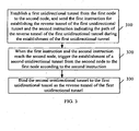
- Step 220 When the first instruction and the path information of the first unidirectional tunnel reach the second node, trigger the establishment of a second unidirectional tunnel from the second node to the first node according to the path information of the first unidirectional tunnel.
- a second tunnel establishment message including the path information for establishing the second unidirectional tunnel is sent from the second node to the first node; and then a second unidirectional tunnel is established from the second node to the first node according to the path information for establishing the second unidirectional tunnel.
- the path information required by the second unidirectional tunnel may be obtained according to the path information of the first unidirectional tunnel. This may be implemented by using multiple methods according to the actual condition.
- the egress node of the first unidirectional tunnel is used as the ingress node of the second unidirectional tunnel, and the egress node of the first unidirectional tunnel and the ingress node of the second unidirectional tunnel are the second node; the ingress node of the first unidirectional tunnel is used as the egress node of the second unidirectional tunnel, and the ingress node of the first unidirectional tunnel and the egress node of the second unidirectional tunnel are the first node.
- the end points of the first unidirectional tunnel and the second unidirectional tunnel are the same.
- the reverse path of the intermediate path of the first unidirectional tunnel may be used as the intermediate path of the second unidirectional tunnel when the path information for establishing the unidirectional second tunnel is obtained according to the path information of the first unidirectional tunnel. That is, the nodes covered by the intermediate path of the first unidirectional tunnel are the same as those covered by the intermediate path of the second unidirectional tunnel.
- the reverse path of the intermediate path of the first unidirectional tunnel may be used as an excluded path of the intermediate path of the second unidirectional tunnel, thus forming a bidirectional tunnel with non-overlapped paths.
- Step 230 Bind the second unidirectional tunnel to the first unidirectional tunnel as the reverse tunnel of the first unidirectional tunnel.
- the second unidirectional tunnel is bound to the first unidirectional tunnel as the reverse tunnel of the first unidirectional tunnel at the first node and the second node that are used as the end points of the tunnel.
- multiple forward tunnels may be bound to a reverse tunnel.
- a third unidirectional tunnel (the path of the third unidirectional tunnel partially overlaps the path of the first unidirectional tunnel) is established from the first node to the second node, and an instruction for establishing the reverse tunnel of the third unidirectional tunnel is sent during the establishment of the third unidirectional tunnel.
- the instruction for establishing the reverse tunnel of the third unidirectional tunnel reaches the second node, if the established second unidirectional tunnel meets the requirements (for example, the tunnel bandwidth requirement) of the reverse tunnel of the third unidirectional tunnel, the second unidirectional tunnel may be bound to the third unidirectional tunnel as the reverse tunnel of the third unidirectional tunnel.
- FIG. 3 is a flowchart of a method for establishing tunnels in Establishment 2 of the present invention.
- the difference between Example 2 and Example 1 includes:
- a second instruction indicating a path of the reverse tunnel of the first unidirectional tunnel and the first instruction are sent during the establishment of the first unidirectional tunnel; and the reverse tunnel of the first unidirectional tunnel is established according to the second instruction.
- the method for establishing tunnels in the example 1 of the present invention includes the following steps:
- Step 310 Establish a first unidirectional tunnel from the first node to the second node, and send the first instruction for establishing the reverse tunnel of the first unidirectional tunnel and a second instruction indicating the path of the reverse tunnel of the first unidirectional tunnel during the establishment of the first unidirectional tunnel.
- the content of the first instruction is the same as that described in Example 1, and thus is not described again.
- the purpose of sending the second instruction is to constrain the path of the reverse tunnel and ensure that the reverse tunnel of the first unidirectional tunnel is established according to a predetermined path and meets specific requirements in some scenarios.
- Step 320 When the first instruction and the second instruction reach the second node, trigger the establishment of a second unidirectional tunnel from the second node to the first node according to the second instruction.
- the second node finds that the second node is the egress node of the first unidirectional tunnel and receives the instruction for establishing the reverse tunnel of the first unidirectional tunnel. Then, the second node triggers the transmission of a second tunnel establishment message to the first node; the second tunnel establishment message carries the path information for establishing the second unidirectional tunnel. Further, during the transmission of the second tunnel establishment message from the second node to the first node, the nodes that the second tunnel establishment message passes through establish a second unidirectional tunnel from the second node to the first node according to the path information for establishing the second unidirectional tunnel.
- path information for establishing the second unidirectional tunnel is obtained according to the received second instruction.
- the path information for establishing the second tunnel carried in the second tunnel establishment message is as follows: the second node -> the third node -> the fourth node -> the first node
- the second instruction provides the following path information of the reverse tunnel:
- the ingress node of the reverse tunnel is the second node, and the egress node of the reverse tunnel is the first node; and the intermediate path between the second node and the first node may be selected freely.
- Step 330 Bind the second unidirectional tunnel to the first unidirectional tunnel as the reverse tunnel of the first unidirectional tunnel. This step is similar to step 230 in Example 1, and thus is not further described.
- FIG. 4 is a flowchart of a method for establishing tunnels in Example 3 of the present invention.
- the difference between Example 3 and Example 2 includes: In Example 3, the first instruction, the path information of the first unidirectional tunnel, and the second instruction are sent during the establishment of the first unidirectional tunnel; and the reverse tunnel of the first unidirectional tunnel is established according to the path information of the first unidirectional tunnel and the second instruction.
- Step 410 Establish a first unidirectional tunnel from the first node to the second node, and send the first instruction for establishing the reverse tunnel of the first unidirectional tunnel, the path information of the first unidirectional tunnel, and the second instruction indicating the path of the reverse tunnel of the first unidirectional tunnel during the establishment of the first unidirectional tunnel.
- Step 420 When the first instruction, the path information of the first unidirectional tunnel, and the second instruction reach the second node, trigger the establishment of a second unidirectional tunnel from the second node to the first node according to the path information of the first unidirectional tunnel and the second instruction.
- the first instruction, the second instruction, and the path information (may include the intermediate path information of the first unidirectional tunnel) of the first unidirectional tunnel are sent.
- the second instruction provides the following path information of the reverse tunnel:
- the reverse path of the intermediate path of the first unidirectional tunnel is used as the intermediate path of the second unidirectional tunnel.
- the nodes covered by the path of the second unidirectional tunnel are the same as those covered by the path of the first unidirectional tunnel.
- the second instruction provides the following path information of the reverse tunnel:
- the reverse path of the intermediate path of the first unidirectional tunnel is used as the excluded path of the intermediate path of the second unidirectional tunnel.
- the intermediate nodes are different except the end points of the tunnels.
- Step 430 Bind the second unidirectional tunnel to the first unidirectional tunnel as the reverse tunnel of the first unidirectional tunnel. This step is the same as step 230 in Example 1, and thus is not further described.
- FIG. 5 is a flowchart of a method for establishing tunnels in Embodiment 4 of the present invention.
- Embodiment 4 takes the establishment of a Multi Protocol Label Switching (MPLS) Traffic Engineering (TE) bidirectional tunnel as an example.
- MPLS Multi Protocol Label Switching
- TE Traffic Engineering
- the forward tunnel refresh message is used to maintain the forward tunnel
- the reverse tunnel refresh message is used to maintain the reverse tunnel. If the reverse tunnel needs to be removed, the removal of the reverse tunnel does not affect the forward tunnel. If the reverse tunnel is down, the forward tunnel may re-trigger the establishment of a reverse tunnel.
- the reverse tunnel establishment process depends on whether the ReverseSession object exists in the received path message and whether the content of the Reverse Session object is the same as the content of the Session object. The details are as follows:
- the first establishment message is processed normally [refer to RFC 2209 and RFC 3209].
- the path message received by the egress node of the tunnel includes the ReverseSession object and the ReverseSession object includes the contents same as those of the Session object in the path message, it indicates that the path message is the path message of the forward tunnel. Then, the reverse tunnel establishment process is triggered.
- the path message received by the egress node of the tunnel includes the ReverseSession object but the ReverseSession object includes contents different from those of the Session object, it indicates that the path message is a path message of the reverse tunnel. Then, the reverse tunnel establishment process is not triggered, thus avoiding repeated establishment of the reverse tunnel.
- whether the establishment of the reverse tunnel is triggered may not depend on whether the path message includes the ReverseSession object and whether the contents of the ReverseSession object are the same as those of the Session. Instead, a flag indicating that a reverse tunnel is to be established in the forward tunnel path message may be sent to the egress node of the forward tunnel.
- the egress node of the forward tunnel triggers the reverse tunnel path message, it is allowed to delete or change the flag indicating that a reverse tunnel is to be established in the reverse tunnel path message, so as to inform the egress node of the reverse tunnel (that is, the ingress node of the forward tunnel) of the information that a reverse tunnel does not need to be established for the reverse tunnel when a reverse tunnel is established. In this way, the establishment of the reverse tunnel may not be repeated.
- the ReverseSessionAttribute object may not be carried in the path message of a forward tunnel. For example, various attributes of the reverse tunnel may be set to default values in advance according to the actual requirements. Thus, when it is necessary to establish a reverse tunnel, the reverse tunnel may be established according to the preset default standard.
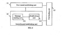
- FIG. 6 shows a logical structure of a system for establishing tunnels in Example 5 of the present invention. Because the tunnel establishment process involves multiple nodes, these nodes may be combined to implement the function of each unit shown in FIG. 6 .
- the system includes a first tunnel establishing unit 61, a second tunnel establishing unit 62, and a first binding unit 63.
- the first tunnel establishing unit 61 is configured to: establish a first unidirectional tunnel from a first node to a second node, and send a first instruction for establishing a reverse tunnel of the first unidirectional tunnel during the establishment of the first unidirectional tunnel.
- the first tunnel establishing unit 61 may send the path information of the first tunnel and/or a second instruction indicating the path of the reverse tunnel of the first unidirectional tunnel while sending the first instruction.
- the first instruction, the path information of the first unidirectional tunnel, and the second instruction are already described in the preceding sections, and are not further described.
- the ingress node of the first unidirectional tunnel is the first node and the egress node is the second node
- intermediate nodes may exist between the ingress node and the egress node.
- the first tunnel establishing unit 61 sends the first instruction and the second instruction.
- the second tunnel establishing unit 62 is configured to trigger the establishment of a second unidirectional tunnel from the second node to the first node when the instruction for establishing the reverse tunnel of the first unidirectional tunnel reaches the second node.
- the second tunnel establishing unit 62 may adopt multiple implementation methods due to the first tunnel establishing unit 61 adopts different implementation methods.
- the first tunnel establishing unit 61 sends the first instruction and the path information of the first unidirectional tunnel during the establishment of the first unidirectional tunnel.
- the second tunnel establishing unit 62 may be configured to trigger the establishment of a second unidirectional tunnel from the second node to the first node according to the path information of the first unidirectional tunnel when the first instruction and the path information of the first unidirectional tunnel reach the second node.
- the method for establishing a second unidirectional tunnel from the second node to the first node according to the path information of the first unidirectional tunnel is already described in the preceding embodiments and examples, and thus is not further described.
- the first tunnel establishing unit 61 sends the first instruction and the second instruction during the establishment of the first unidirectional tunnel.
- the second tunnel establishing unit 62 may be configured to trigger the establishment of a second unidirectional tunnel from the second node to the first node according to the second instruction when the first instruction and the second instruction reach the second node.
- the method for establishing a second unidirectional tunnel from the second node to the first node according to the second instruction is already described in the preceding embodiments and examples, and thus is not further described.
- the first tunnel establishing unit 61 sends the first instruction, the path information of the first unidirectional tunnel, and the second instruction during the establishment of the first unidirectional tunnel.
- the second tunnel establishing unit 62 may be configured to trigger the establishment of a second unidirectional tunnel from the second node to the first node according to the path information of the first unidirectional tunnel and the second instruction when the first instruction, the path information of the first tunnel, and the second instruction reach the second node.
- the method for establishing a second unidirectional tunnel from the second node to the first node according to the path information of the first unidirectional tunnel and the second instruction is already described in the preceding embodiments and examples, and thus is not further described.
- the following describes a specific structure of the second tunnel establishing unit 62.
- the second tunnel establishing unit 62 includes a message sending unit 521 and an establishing unit 522.
- the message sending unit 521 is configured to: when the first instruction reaches the second node, send a second tunnel establishment message that carries the path information for establishing the second unidirectional tunnel from the second node to the first node.
- the establishing unit 522 is configured to establish a second unidirectional tunnel from the second node to the first node according to the path information for establishing the second unidirectional tunnel. Similar to the second tunnel establishing unit 62 that may adopt multiple methods to establish the second unidirectional tunnel, the message sending unit 521 in the second tunnel establishing unit 62 may adopt multiple implementation methods.
- the first tunnel establishing unit 61 sends the first instruction and the path information of the first unidirectional tunnel during the establishment of the first unidirectional tunnel
- the message sending unit 521 includes a path obtaining unit and a constructing-and-sending unit.
- the path obtaining unit is configured to obtain the path information for establishing the second unidirectional tunnel according to the path information of the first unidirectional tunnel when the first instruction and the path information of the first unidirectional tunnel reach the second node.
- the constructing-and-sending unit is configured to: construct a second tunnel establishment message that carries the path information for establishing the second unidirectional tunnel, and send the second tunnel establishment message from the second node to the first node.
- the first tunnel establishing unit 61 sends the first instruction and the second instruction during the establishment of the first unidirectional tunnel
- the message sending unit 521 includes a path obtaining unit and a constructing-and-sending unit.
- the path obtaining unit is configured to obtain the path information for establishing the second unidirectional tunnel according to the second instruction when the first instruction and the second instruction reach the second node.
- the constructing-and-sending unit is configured to: construct a second tunnel establishment message that carries the path information for establishing the second unidirectional tunnel, and send the second tunnel establishment message from the second node to the first node.
- the first tunnel establishing unit 61 sends the first instruction, the path information of the first unidirectional tunnel, and the second instruction during the establishment of the first unidirectional tunnel
- the message sending unit 521 includes a path obtaining unit and a constructing-and-sending unit.
- the path obtaining unit is configured to obtain the path information for establishing a second unidirectional tunnel according to the path information of the first tunnel and the second instruction when the first instruction, the path information of the first unidirectional tunnel, and the second instruction reach the second node.
- the constructing-and-sending unit is configured to: construct a second tunnel establishment message that carries the path informations for establishing the second unidirectional tunnel, and send the second tunnel establishment message from the second node to the first node.
- the second tunnel establishing unit 62 may adopt multiple implementation methods. Accordingly, the second tunnel establishing unit 62 may establish multiple paths of the second unidirectional tunnel. Because the end point of the second unidirectional tunnel is the same as that of the first unidirectional tunnel, the change of the path of the second unidirectional tunnel is reflected by the change of the intermediate path between the end points of the tunnel. For example, the nodes covered by the intermediate path of the second unidirectional tunnel are the same as those covered by the intermediate path of the first unidirectional tunnel. In this case, the intermediate path of the second unidirectional tunnel is the reverse path of the intermediate path of the first unidirectional tunnel, thus ensuring that the first unidirectional tunnel and the second unidirectional tunnel pass through the same nodes.
- the nodes covered by the intermediate path of the second unidirectional tunnel are different from those covered by the intermediate path of the first unidirectional tunnel. In another example, some of the nodes covered by the intermediate path of the second unidirectional tunnel are the same as those covered by the intermediate path of the first unidirectional tunnel.
- the first binding unit 63 is configured to bind the second unidirectional tunnel to the first unidirectional tunnel as the reverse tunnel of the first unidirectional tunnel.
- the end points (that is, the first node and the second node) of the first unidirectional tunnel and the second unidirectional tunnel bind the first unidirectional tunnel to the second unidirectional tunnel.
- more than two forward tunnels with different paths and same direction may be established between two nodes.
- the third unidirectional tunnel another tunnel (hereinafter referred to as the third unidirectional tunnel) is established from the first node to the second node and a reverse tunnel of the third unidirectional tunnel needs to be established
- the second unidirectional tunnel may be bound to the third unidirectional tunnel as the reverse tunnel of the third unidirectional tunnel if the reverse tunnel of the third unidirectional tunnel has no bandwidth requirement or the second unidirectional tunnel can meet the attribute requirement of the reverse tunnel of the third unidirectional tunnel.
- system provided in this example further includes:
- the second tunnel may be used as the reverse tunnel of the first unidirectional tunnel, or the second unidirectional tunnel may be used as the reverse tunnel of the third unidirectional tunnel, thus saving the tunnel establishment resources.
- multiple forward tunnels may be bound to one reverse tunnel.
- an instruction for establishing the reverse tunnel is sent during the establishment of a forward tunnel; when the instruction reaches the egress node of the forward tunnel, the establishment of reverse tunnel is triggered; and a bidirectional tunnel is automatically established. Because the bidirectional tunnel can be automatically established, the applicability of the tunnel technology is enhanced. For example, a tunnel and a multicast service may be deployed on a same network. In another example, because the bidirectional tunnel ensures that the forward tunnel and the reverse tunnel pass through the same nodes, Bidirectional Forwarding Detection (BFD) may be used to detect link failures.
- BFD Bidirectional Forwarding Detection
- the forward BFD packet is forwarded according to the RSVP-TE LSP when the RSVP-TE LSP connectivity is detected through BFD.
- the reverse BFD packet may be forwarded according to the IP address. In this way, it cannot be guaranteed that the forward path and the reverse path of the BFD packet are the same, thus bringing about an unreliable BFD result.
Landscapes
- Engineering & Computer Science (AREA)
- Computer Networks & Wireless Communication (AREA)
- Signal Processing (AREA)
- Data Exchanges In Wide-Area Networks (AREA)
- Mobile Radio Communication Systems (AREA)
Description
- The present invention relates to communications technologies, and in particular, to a method and system for establishing tunnels.
- The Traffic Engineering (TE) tunnel may provide a reliable Quality of Service (QoS) mechanism. It guarantees the bandwidth and supports features such as affinity, explicit path, and preemption. In addition, the TE tunnel has a backup protection mechanism, such as partial protection (fast re-routing) and end-to-end protection (including hot standby protection and tunnel group protection).
- Because the current TE tunnel is unidirectional, it cannot support some specific scenarios, failing to meet some specific requirements.
- For example, when a Resource Reservation Protocol - Traffic Engineering (RSVP-TE) tunnel and a multicast service need to be deployed on a same network, the multicast function may be affected if multicast traffic is carried on the TE tunnel, that is, when multicast packets are forwarded through the TE tunnel.
- As shown in
FIG. 1 , a forward TE tunnel is established from router A (RTA) to router C (RTC). When a multicast signaling packet is sent from RTA to RTC, the multicast signaling packet goes through the TE tunnel. Thus, router B (RTB) does not process the multicast packet, nor does it have related multicast forwarding entries. When the traffic is returned from router D (RTD) to RTA through RTC and RTB, the traffic can reach RTA only when it undergoes the IP forwarding by RTB. RTB; however, does not have multicast forwarding entries. Thus, the multicast traffic is lost. -
WO0195583A2 - RFC 4874 describes: ways to communicate route exclusions during path setup using Resource ReserVation Protocol-Traffic Engineering (RSVP-TE).
- According to different aspects of the present invention, a method for establishing tunnels is provided.
- A method for establishing a multi protocol label switching, MPLS, traffic engineering, TE, bidirectional tunnel, including:
- initiating (1), by a first node (RTA), the establishment of a bidirectional tunnel, comprising sending, by the first node (RTA), a resource reservation protocol traffic engineering, RSVP-TE, Path message to a second node (RTC) through an intermediate node (RTB), when establishing a first unidirectional tunnel;
- wherein the RSVP-TE Path message carries Session object and SessionAttribute object of the current protocol standard, and Reverse Session object and ReverseSession Attribute objects, wherein the ReverseSession Attribute object specifies the requirement for the reverse tunnel, wherein the content of the ReverseSession object is the same as the content of the Session object;
- receiving (2), by the intermediate node (RTB), the RSVP-TE Path message sent from the first node (RTA), and establishing a forward tunnel;
- receiving (3), by the second node (RTC), the RSVP-TE Path message sent from the intermediate node (RTB), finding that the RSVP-TE Path message already reaches the egress node of the forward tunnel, and then sending a reservation, Resv, message of the forward tunnel to the first node (RTA);
- initiating, by the second node (RTC), the establishment of a reverse tunnel and constructing (4) a path message of the reverse tunnel to be sent to the first node (RTA), after the second node (RTC) finds that the RSVP-TE Path message carries the ReverseSession object and that the content of the ReverseSession object is the same as the content of the Session object;
- calculating (5), by the second node (RTC) an Explicit Route Object, ERO, by invoking Constrained Shortest Path First, CSPF, according to a Flag field of the ReverseSessionAttribute object carried in the RSVP-TE Path message and Record Route Object, RRO, in the RSVP-TE Path message;
- sending (6), by the second node (RTC), the path message of the reverse tunnel to the first node (RTA), wherein the path message of the reverse tunnel carries a Session object, a SessionAttribute object, a ReverseSession object, a ReverseSessionAttribute object and the calculated ERO, wherein resource affinity information and bandwidth in the SessionAttribute object comes from the ReverseSessionAttribute object carried in the RSVP-TE, Path message, wherein the content of the ReverseSession object is the same as the content of the Session object carried in the RSVP-TE, Path message, wherein the content of the ReverseSessionAttribute object is the same as the content of the SessionAttribute object in the RSVP-TE, Path message;
- recording (6), by the second node (RTC), the information of the forward tunnel corresponding to the reverse tunnel;
- receiving (7), by an intermediate node (RTB), the path message of the reverse tunnel sent from the second node (RTC), and establishing a reverse tunnel according to the content in the path message of the reverse tunnel;
- sending (8), by the first node (RTA), a ResvConfirm message indicating the successful establishment of the forward tunnel to the second node (RTC), after receiving the Resv message from the second node (RTC);
- sending (9), by the first node (RTA), a Resv message of the reverse tunnel to the second node (RTC), after receiving the path message of the reverse tunnel from the second node (RTC) and finding that the node is the egress node of the reverse tunnel;
- recording, by the first node (RTA), the reverse tunnel information being the content in the ReverseSession object of the path message of the reverse tunnel;
- binding (10), by the second node (RTC), the forward tunnel to the reverse tunnel, after receiving the ResvConfirm message indicating the successful establishment of the forward tunnel from the first node (RTA), and sending (11) a ResvConfirm message indicating the successful establishment of the reverse tunnel to the first node (RTA);
- binding (12), by the first node (RTA), the forward tunnel to the reverse tunnel, after receiving the ResvConfirm message indicating the successful establishment of the reverse tunnel from the second node (RTC).
- A system for establishing a multi protocol label switching, MPLS, traffic engineering, TE, bidirectional tunnel, comprising a first node (RTA), an intermediate node (RTB) and a second node (RTC), wherein
the first node (RTA) is configured to initiate the establishment of a bidirectional tunnel, the initiating the establishment of a bidirectional tunnel, comprises: the first node (RTA) sends a resource reservation protocol traffic engineering, RSVP-TE, Path message to the second node (RTC) through the intermediate node (RTB), when establishing a first unidirectional tunnel;
wherein the RSVP-TE Path message carries Session object and SessionAttribute object of the current protocol standard, and Reverse Session object and ReverseSession Attribute objects, wherein the ReverseSession Attribute object specifies the requirement for the reverse tunnel, wherein the content of the ReverseSession object is the same as the content of the Session object;
the intermediate node (RTB) is configured to receive the RSVP-TE Path message sent from the first node (RTA), and establish a forward tunnel;
the second node (RTC) is configured to receive the RSVP-TE Path message sent from the intermediate node (RTB), find that the RSVP-TE Path message already reaches the egress node of the forward tunnel, and then send a reservation, Resv, message of the forward tunnel to the first node (RTA);
the second node (RTC) is further configured to initiate the establishment of a reverse tunnel and construct a path message of the reverse tunnel to be sent to the first node (RTA), after the second node (RTC) finds that the RSVP-TE Path message carries the ReverseSession object and that the content of the ReverseSession object is the same as the content of the Session object;
the second node (RTC) is further configured to calculate an Explicit Route Object, ERO, by invoking Constrained Shortest Path First, CSPF, according to a Flag field of the ReverseSessionAttribute object carried in the RSVP-TE Path message and Record Route Object, RRO, in the RSVP-TE Path message;
the second node (RTC) is further configured to send the path message of the reverse tunnel to the first node (RTA), wherein the path message of the reverse tunnel carries a Session object, a SessionAttribute object, a ReverseSession object, a ReverseSessionAttribute object and the calculated ERO wherein resource affinity information and bandwidth in the SessionAttribute object comes from the ReverseSessionAttribute object carried in the RSVP-TE, Path message, wherein the content of the ReverseSession object is the same as the content of the Session object carried in the RSVP-TE, Path message, wherein the content of the ReverseSessionAttribute object is the same as the content of the SessionAttribute object in the RSVP-TE, Path message;
the second node (RTC) is further configured to record the information of the forward tunnel corresponding to the reverse tunnel;
the intermediate node (RTB) is further configured to receive the path message of the reverse tunnel sent from the second node (RTC), and establish a reverse tunnel according to the content in the path message of the reverse tunnel;
the first node (RTA) is further configured to send a ResvConfirm message indicating the successful establishment of the forward tunnel to the second node (RTC), after receiving the Resv message from the second node (RTC);
the first node (RTA) is further configured to send a Resv message of the reverse tunnel to the second node (RTC), after receiving the path message of the reverse tunnel from the second node (RTC) and finding that the node is the egress node of the reverse tunnel;
the first node (RTA) is further configured to record the reverse tunnel information being the content in the ReverseSession object of the path message of the reverse tunnel;
the second node (RTC) is further configured to bind the forward tunnel to the reverse tunnel, after receiving the ResvConfirm message indicating the successful establishment of the forward tunnel from the first node (RTA), and send a ResvConfirm message indicating the successful establishment of the reverse tunnel to the first node (RTA);
the first node (RTA) is further configured to bind the forward tunnel to the reverse tunnel, after receiving the ResvConfirm message indicating the successful establishment of the reverse tunnel from the second node (RTC). - According to the different aspects of the present invention, the instruction for establishing the reverse tunnel of the first unidirectional tunnel is sent during the establishment of the first unidirectional tunnel; when the instruction reaches the egress node (that is, the second node) of the first unidirectional tunnel, the establishment of the reverse tunnel of the first unidirectional tunnel is triggered. Thus, a bidirectional tunnel is established conveniently and the scenario of the tunnel technology is enriched.
-
-
FIG. 1 is a schematic diagram illustrating a tunnel in the prior art; -
FIG. 2 is a flowchart of a method for establishing tunnels in Example 1 of the present invention; -
FIG. 3 is a flowchart of a method for establishing tunnels in Example 2 of the present invention; -
FIG. 4 is a flowchart of a method for establishing tunnels in Example 3 of the present invention; -
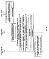
FIG. 5 is a flowchart of a method for establishing tunnels inEmbodiment 4 of the present invention; and -
FIG. 6 shows a logical structure of a system for establishing tunnels in Example 5 of the present invention. - A tunnel at least includes one ingress node and one egress node. In general, other nodes exist between the ingress node and the egress node. Therefore, for better description of embodiments of the present invention, other nodes between the ingress node and the egress node of a tunnel are called intermediate nodes, and a path formed by these intermediate nodes is called an intermediate path.
- As shown in
FIG. 2 , the method for establishing tunnels in Example 1 of the present invention includes the following steps: - Step 210: Establish a first unidirectional tunnel from the first node to the second node, and send the first instruction for establishing the reverse tunnel of the first unidirectional tunnel and the path information of the first unidirectional tunnel during the establishment of the first unidirectional tunnel.
- During the establishment of a unidirectional tunnel, generally the ingress node of the tunnel sends a tunnel establishment message (for example, an RSVP-TE Path message) to the egress node of the unidirectional tunnel, where the tunnel establishment message carries path information of the first unidirectional tunnel, such as address of the ingress node and address of the egress node of the first unidirectional tunnel. The difference between Example 1 and the prior art includes: In Example 1, a first instruction for establishing the reverse tunnel of the first unidirectional tunnel needs to be sent, so that the first instruction may reach the egress node (the second node) of the first unidirectional tunnel. The first instruction is generally sent during the establishment of the first unidirectional tunnel. The first instruction may be identified in multiple forms, for example, it may use a special ID or a special object, so long as the request for establishing the reverse tunnel can be identified from the first instruction according to a predetermined agreement.
- Step 220: When the first instruction and the path information of the first unidirectional tunnel reach the second node, trigger the establishment of a second unidirectional tunnel from the second node to the first node according to the path information of the first unidirectional tunnel.
- For example, when the first instruction reaches the second node, a second tunnel establishment message including the path information for establishing the second unidirectional tunnel is sent from the second node to the first node; and then a second unidirectional tunnel is established from the second node to the first node according to the path information for establishing the second unidirectional tunnel.
The path information required by the second unidirectional tunnel may be obtained according to the path information of the first unidirectional tunnel. This may be implemented by using multiple methods according to the actual condition. For example, the egress node of the first unidirectional tunnel is used as the ingress node of the second unidirectional tunnel, and the egress node of the first unidirectional tunnel and the ingress node of the second unidirectional tunnel are the second node; the ingress node of the first unidirectional tunnel is used as the egress node of the second unidirectional tunnel, and the ingress node of the first unidirectional tunnel and the egress node of the second unidirectional tunnel are the first node. In this way, it can be guaranteed that the end points of the first unidirectional tunnel and the second unidirectional tunnel are the same. - Optionally, if nodes of the first unidirectional tunnel include intermediate nodes besides the ingress node (the first node) and the egress node (the second node), and the first path information sent through the first unidirectional tunnel further includes intermediate path information, the reverse path of the intermediate path of the first unidirectional tunnel may be used as the intermediate path of the second unidirectional tunnel when the path information for establishing the unidirectional second tunnel is obtained according to the path information of the first unidirectional tunnel. That is, the nodes covered by the intermediate path of the first unidirectional tunnel are the same as those covered by the intermediate path of the second unidirectional tunnel. This can guarantee that the nodes of the first unidirectional tunnel are the same as the nodes of the second unidirectional tunnel, thus forming a bidirectional tunnel with fully overlapped paths. Certainly, the reverse path of the intermediate path of the first unidirectional tunnel may be used as an excluded path of the intermediate path of the second unidirectional tunnel, thus forming a bidirectional tunnel with non-overlapped paths.
- When the reverse path of the intermediate path of the first unidirectional tunnel is used as an excluded path of the intermediate path of the second unidirectional tunnel, the following two cases are included:
- Case 1: The reverse path of the intermediate path of the first unidirectional tunnel does not overlap the intermediate path of the second unidirectional tunnel. That is, except the ingress node and the egress node, none of the nodes covered by the intermediate paths of the first unidirectional tunnel is the same as any of the nodes covered by the intermediate paths of the second unidirectional tunnel.
- Case 2: The reverse path of the intermediate path of the first tunnel partially overlaps the intermediate path of the second unidirectional tunnel. That is, except the ingress node and the egress node, some of the nodes covered by the intermediate path of the first unidirectional tunnel are the same as some of the nodes covered by the intermediate path of the second unidirectional tunnel.
- Step 230: Bind the second unidirectional tunnel to the first unidirectional tunnel as the reverse tunnel of the first unidirectional tunnel.
- For example, the second unidirectional tunnel is bound to the first unidirectional tunnel as the reverse tunnel of the first unidirectional tunnel at the first node and the second node that are used as the end points of the tunnel.
- In addition, multiple forward tunnels may be bound to a reverse tunnel. For example, after the first unidirectional tunnel is established, a third unidirectional tunnel (the path of the third unidirectional tunnel partially overlaps the path of the first unidirectional tunnel) is established from the first node to the second node, and an instruction for establishing the reverse tunnel of the third unidirectional tunnel is sent during the establishment of the third unidirectional tunnel. After the instruction for establishing the reverse tunnel of the third unidirectional tunnel reaches the second node, if the established second unidirectional tunnel meets the requirements (for example, the tunnel bandwidth requirement) of the reverse tunnel of the third unidirectional tunnel, the second unidirectional tunnel may be bound to the third unidirectional tunnel as the reverse tunnel of the third unidirectional tunnel.
-
FIG. 3 is a flowchart of a method for establishing tunnels inEstablishment 2 of the present invention. The difference between Example 2 and Example 1 includes: In Example 2, a second instruction indicating a path of the reverse tunnel of the first unidirectional tunnel and the first instruction are sent during the establishment of the first unidirectional tunnel; and the reverse tunnel of the first unidirectional tunnel is established according to the second instruction. As shown inFIG. 2 , the method for establishing tunnels in the example 1 of the present invention includes the following steps: - Step 310: Establish a first unidirectional tunnel from the first node to the second node, and send the first instruction for establishing the reverse tunnel of the first unidirectional tunnel and a second instruction indicating the path of the reverse tunnel of the first unidirectional tunnel during the establishment of the first unidirectional tunnel.
- The content of the first instruction is the same as that described in Example 1, and thus is not described again. The purpose of sending the second instruction is to constrain the path of the reverse tunnel and ensure that the reverse tunnel of the first unidirectional tunnel is established according to a predetermined path and meets specific requirements in some scenarios.
- Step 320: When the first instruction and the second instruction reach the second node, trigger the establishment of a second unidirectional tunnel from the second node to the first node according to the second instruction.
- Specifically, when the first instruction reaches the second node, the second node finds that the second node is the egress node of the first unidirectional tunnel and receives the instruction for establishing the reverse tunnel of the first unidirectional tunnel. Then, the second node triggers the transmission of a second tunnel establishment message to the first node; the second tunnel establishment message carries the path information for establishing the second unidirectional tunnel. Further, during the transmission of the second tunnel establishment message from the second node to the first node, the nodes that the second tunnel establishment message passes through establish a second unidirectional tunnel from the second node to the first node according to the path information for establishing the second unidirectional tunnel.
- It may be noted that the path information for establishing the second unidirectional tunnel is obtained according to the received second instruction. Some specific implementation methods are given below:
- For example, if the second instruction provides a specific path of the reverse tunnel as follows: the second node -> the third node -> the fourth node -> the first node, the path information for establishing the second tunnel carried in the second tunnel establishment message is as follows: the second node -> the third node -> the fourth node -> the first node
- In another example, the second instruction provides the following path information of the reverse tunnel: The ingress node of the reverse tunnel is the second node, and the egress node of the reverse tunnel is the first node; and the intermediate path between the second node and the first node may be selected freely.
- Step 330: Bind the second unidirectional tunnel to the first unidirectional tunnel as the reverse tunnel of the first unidirectional tunnel. This step is similar to step 230 in Example 1, and thus is not further described.
-
FIG. 4 is a flowchart of a method for establishing tunnels in Example 3 of the present invention. The difference between Example 3 and Example 2 includes: In Example 3, the first instruction, the path information of the first unidirectional tunnel, and the second instruction are sent during the establishment of the first unidirectional tunnel; and the reverse tunnel of the first unidirectional tunnel is established according to the path information of the first unidirectional tunnel and the second instruction. - Step 410: Establish a first unidirectional tunnel from the first node to the second node, and send the first instruction for establishing the reverse tunnel of the first unidirectional tunnel, the path information of the first unidirectional tunnel, and the second instruction indicating the path of the reverse tunnel of the first unidirectional tunnel during the establishment of the first unidirectional tunnel.
- Step 420: When the first instruction, the path information of the first unidirectional tunnel, and the second instruction reach the second node, trigger the establishment of a second unidirectional tunnel from the second node to the first node according to the path information of the first unidirectional tunnel and the second instruction.
- For example, during the establishment of the first unidirectional tunnel, the first instruction, the second instruction, and the path information (may include the intermediate path information of the first unidirectional tunnel) of the first unidirectional tunnel are sent. The second instruction provides the following path information of the reverse tunnel: The reverse path of the intermediate path of the first unidirectional tunnel is used as the intermediate path of the second unidirectional tunnel. In this case, the nodes covered by the path of the second unidirectional tunnel are the same as those covered by the path of the first unidirectional tunnel.
- In another example, the second instruction provides the following path information of the reverse tunnel: The reverse path of the intermediate path of the first unidirectional tunnel is used as the excluded path of the intermediate path of the second unidirectional tunnel. In this case, among the nodes covered by the paths of the second unidirectional tunnel and the first unidirectional tunnel, the intermediate nodes are different except the end points of the tunnels.
- Step 430: Bind the second unidirectional tunnel to the first unidirectional tunnel as the reverse tunnel of the first unidirectional tunnel. This step is the same as
step 230 in Example 1, and thus is not further described. - For better description of the preceding embodiment of the present invention, the following describes a specific implementation method of the preceding embodiment.
FIG. 5 is a flowchart of a method for establishing tunnels inEmbodiment 4 of the present invention.Embodiment 4 takes the establishment of a Multi Protocol Label Switching (MPLS) Traffic Engineering (TE) bidirectional tunnel as an example. - 1. Router A (RTA) initiates the establishment of a bidirectional tunnel.
For example, RTA sends an RSVP-TE Path message (for better description, the path message sent in case of establishment of a forward tunnel is hereinafter referred to as the first establishment message ) to RTC through RTB, where the RSVP-TE Path message carries Session and SessionAttribute of the current protocol standard and two new objects (Reverse Session and ReverseSession Attribute).
The content of the ReverseSession object is same as the content of the Session object. For example, the Reverse Session object is defined as follows:
The tunnel end point address (the destination address of the tunnel) of the Internet Protocol version 4 (IPv4) is the RTC address of the egress node RTC of the first tunnel. The Tunnel ID is a tunnel ID allocated to the first tunnel by the ingress node RTA of the first tunnel. The Extended Tunnel ID is the RTA address of the ingress node RTA of the first tunnel.
The content in the ReverseSessionAttribute object may specify the requirement for the reverse tunnel. For example, the ReverseSessionAttribute object is defined as follows:

The Flags indicate the path information of the reverse tunnel or other information about the reverse tunnel. For example:
The 0x00 bit flag may indicate that the path of the reverse tunnel corresponds to the path of the forward tunnel in turn. For example, if the path of the forward tunnel is RTA-RTB-RTC, the path of the reverse tunnel must be RTC-RTB-RTA.
The 0x01 bit flag may indicate that the path of the reverse tunnel does not correspond to the path of the forward tunnel (except the nodes at both ends of the tunnel). For example, if the path of the forward tunnel is RTA-RTB-RTC, the path of the reverse tunnel must be RTC-a node other than RTB-RTA.
The 0x02 bit flag may indicate that the path of the reverse tunnel (except the nodes at both ends of the tunnel) may be selected freely. For example, if the path of the forward tunnel is RTA-RTB-RTC, the ingress node of the reverse tunnel is RTC, the egress node is RTA, and the node between RTC and RTA is not limited.
The 0x04 bit flag may indicate that the information of the reverse tunnel undergoes the flooding of the Interior Gateway Protocol (IGP)-shortcut.
The 0x08 bit flag may indicate that the information of the reverse tunnel undergoes the flooding of the Forwarding-Adjacency.
The 0x10 bit flag may indicate that the reverse tunnel undergoes hot standby class end-to-end protection.
The Setup Priority may indicate the setup priority of the reverse tunnel. It may range from 0 to 7, with 0 indicating the highest priority. The Holding Priority may indicate the holding priority of the reverse tunnel. It may range from 0 to 7, with 0 indicating the highest priority. The Bandwidth may indicate the bandwidth information of the reverse tunnel.
Because the content of the new ReverseSessionAttribute object is similar to the content of the SessionAttribute object of the current protocol standard (The ReverseSessionAttribute object describes the session attribute of the reverse tunnel, while the SessionAttribute object describes the session attribute information of the forward tunnel), these attributes are not further described. - 2. RTB receives a first establishment message (carrying the path message of the ReverseSession object) sent from RTA, and establishes a forward tunnel (equivalent to the first tunnel in Example 1).
- 3. RTC receives a first establishment message sent from RTB, and finds that the first establishment message already reaches the egress node of the forward tunnel. Then, RTC sends a reservation (Resv) message of the forward tunnel to the upstream node (that is, RTA).
- 4. After finding that the first establishment message carries the ReverseSession object and that the content of the ReverseSession object is the same as the content of the Session object, RTC initiates the establishment of a reverse tunnel (equivalent to the second tunnel in Example 2), and constructs a path message of the reverse tunnel (hereinafter referred to as the second tunnel establishment message) to be sent to RTA.
The content of the Session object carried in the second tunnel establishment message may come from the content of the ReverseSession object carried in the first establishment message, but the contents of the Session object and the ReverseSession object are basically contrary. For example, the tunnel end point address of the Session object in the second tunnel establishment message is the RTA address (that is, the Extended Tunnel ID of the ReverseSession object in the first establishment message). The Extended Tunnel ID in the second tunnel establishment message is the RTA address (that is, the tunnel end point address of the ReverseSession object in the first establishment message).
The information such as resource affinity (RA) and bandwidth in the SessionAttribute object carried in the second tunnel establishment message comes from the ReverseSessionAttribute object carried in the path information of the forward tunnel.
The content of the ReverseSession object carried in the second tunnel establishment message is the same as the content of the Session object carried in the first establishment message.
The content of the ReverseSessionAttribute object carried in the second tunnel establishment message is the same as the content of the SessionAttribute object carried in the first establishment message. - 5. RTC calculates an Explicit Route Object (ERO, indicating the path that the second tunnel establishment message must go through) by invoke Constrained Shortest Path First (CSPF) according to the flag of the ReverseSessionAttribute object carried in the first establishment message and the Record Route Object (RRO, recording the path that the message already passes through) in the first establishment message.
- 6. Trigger the establishment of a reverse tunnel according to the preceding information. Specifically, RTC sends the second tunnel establishment message that carries the Session object, the SessionAttribute object, the ReverseSession object, and the ReverseSessionAttribute object in
step 4 and the ERO instep 5 to RTA. In addition, RTC records the information of the forward tunnel corresponding to the reverse tunnel. - 7. RTB receives the second tunnel establishment message from RTC, and establishes a reverse tunnel according to the content in the second tunnel establishment message.
- 8. After receiving the Resv message from RTC, RTA sends a ResvConfirm message indicating the successful establishment of the forward tunnel to RTC.
- 9. After receiving the second tunnel establishment message from RTC, RTA finds that the node is the egress node of the reverse tunnel. Then, RTA sends a Resv message of the reverse tunnel to RTC. In addition, RTA records the reverse tunnel information in the second tunnel establishment message. According to the preceding description, the reverse tunnel information in the second tunnel establishment message (that is, the path message of reverse tunnel) refers to the content in the ReverseSession object. The content of the ReverseSession object in the second tunnel establishment message, however, is exactly the content of the Session object in the first establishment message (that is, the path message of the forward tunnel).
- 10. After receiving the ResvConfirm message indicating the successful establishment of the forward tunnel from RTA, RTC binds the forward tunnel to the reverse tunnel.
- 11. After receiving the Resv message of the reverse tunnel from RTA, RTC sends a ResvConfirm message indicating the successful establishment of the reverse tunnel to RTA.
- 12. After receiving the ResvConfirm message indicating the successful establishment of the reverse tunnel from RTC, RTA binds the forward tunnel to the reverse tunnel.
- After the forward tunnel is established, details on how to hold and process the soft state of the forward tunnel may be referred to the prior art, for example, Request for Comments (RFC) 2205 and RFC 3209. Details on how to hold and process the soft state of the reverse tunnel may also be referred to RFC 2205 and RFC 3209. The forward tunnel refresh message is used to maintain the forward tunnel, and the reverse tunnel refresh message is used to maintain the reverse tunnel. If the reverse tunnel needs to be removed, the removal of the reverse tunnel does not affect the forward tunnel. If the reverse tunnel is down, the forward tunnel may re-trigger the establishment of a reverse tunnel.
- According to the preceding implementation method, the reverse tunnel establishment process depends on whether the ReverseSession object exists in the received path message and whether the content of the Reverse Session object is the same as the content of the Session object. The details are as follows:
- If the path message received by the egress node of the tunnel does not include the ReverseSession object, the first establishment message is processed normally [refer to RFC 2209 and RFC 3209].
- If the path message received by the egress node of the tunnel includes the ReverseSession object and the ReverseSession object includes the contents same as those of the Session object in the path message, it indicates that the path message is the path message of the forward tunnel. Then, the reverse tunnel establishment process is triggered.
- If the path message received by the egress node of the tunnel includes the ReverseSession object but the ReverseSession object includes contents different from those of the Session object, it indicates that the path message is a path message of the reverse tunnel. Then, the reverse tunnel establishment process is not triggered, thus avoiding repeated establishment of the reverse tunnel.
- The following describes several alternative methods of the preceding implementation methods. Firstly, whether the establishment of the reverse tunnel is triggered may not depend on whether the path message includes the ReverseSession object and whether the contents of the ReverseSession object are the same as those of the Session. Instead, a flag indicating that a reverse tunnel is to be established in the forward tunnel path message may be sent to the egress node of the forward tunnel. When the egress node of the forward tunnel triggers the reverse tunnel path message, it is allowed to delete or change the flag indicating that a reverse tunnel is to be established in the reverse tunnel path message, so as to inform the egress node of the reverse tunnel (that is, the ingress node of the forward tunnel) of the information that a reverse tunnel does not need to be established for the reverse tunnel when a reverse tunnel is established. In this way, the establishment of the reverse tunnel may not be repeated. Secondly, the ReverseSessionAttribute object may not be carried in the path message of a forward tunnel. For example, various attributes of the reverse tunnel may be set to default values in advance according to the actual requirements. Thus, when it is necessary to establish a reverse tunnel, the reverse tunnel may be established according to the preset default standard.
-
FIG. 6 shows a logical structure of a system for establishing tunnels in Example 5 of the present invention. Because the tunnel establishment process involves multiple nodes, these nodes may be combined to implement the function of each unit shown inFIG. 6 . The system includes a firsttunnel establishing unit 61, a secondtunnel establishing unit 62, and a firstbinding unit 63. - The first
tunnel establishing unit 61 is configured to: establish a first unidirectional tunnel from a first node to a second node, and send a first instruction for establishing a reverse tunnel of the first unidirectional tunnel during the establishment of the first unidirectional tunnel. Optionally, the firsttunnel establishing unit 61 may send the path information of the first tunnel and/or a second instruction indicating the path of the reverse tunnel of the first unidirectional tunnel while sending the first instruction. The first instruction, the path information of the first unidirectional tunnel, and the second instruction are already described in the preceding sections, and are not further described. Although the ingress node of the first unidirectional tunnel is the first node and the egress node is the second node, intermediate nodes may exist between the ingress node and the egress node. Compared with the prior art, only the following information is added in this example: the firsttunnel establishing unit 61 sends the first instruction and the second instruction. Thus, details on how to establish the first unidirectional tunnel may be referred to the prior art, and are not further described. - The second
tunnel establishing unit 62 is configured to trigger the establishment of a second unidirectional tunnel from the second node to the first node when the instruction for establishing the reverse tunnel of the first unidirectional tunnel reaches the second node. The secondtunnel establishing unit 62 may adopt multiple implementation methods due to the firsttunnel establishing unit 61 adopts different implementation methods. - For example, the first
tunnel establishing unit 61 sends the first instruction and the path information of the first unidirectional tunnel during the establishment of the first unidirectional tunnel. In this way, the secondtunnel establishing unit 62 may be configured to trigger the establishment of a second unidirectional tunnel from the second node to the first node according to the path information of the first unidirectional tunnel when the first instruction and the path information of the first unidirectional tunnel reach the second node. The method for establishing a second unidirectional tunnel from the second node to the first node according to the path information of the first unidirectional tunnel is already described in the preceding embodiments and examples, and thus is not further described. - In another example, the first
tunnel establishing unit 61 sends the first instruction and the second instruction during the establishment of the first unidirectional tunnel. In this way, the secondtunnel establishing unit 62 may be configured to trigger the establishment of a second unidirectional tunnel from the second node to the first node according to the second instruction when the first instruction and the second instruction reach the second node. The method for establishing a second unidirectional tunnel from the second node to the first node according to the second instruction is already described in the preceding embodiments and examples, and thus is not further described. - In another example, the first
tunnel establishing unit 61 sends the first instruction, the path information of the first unidirectional tunnel, and the second instruction during the establishment of the first unidirectional tunnel. In this way, the secondtunnel establishing unit 62 may be configured to trigger the establishment of a second unidirectional tunnel from the second node to the first node according to the path information of the first unidirectional tunnel and the second instruction when the first instruction, the path information of the first tunnel, and the second instruction reach the second node. The method for establishing a second unidirectional tunnel from the second node to the first node according to the path information of the first unidirectional tunnel and the second instruction is already described in the preceding embodiments and examples, and thus is not further described. - The following describes a specific structure of the second
tunnel establishing unit 62. - The second
tunnel establishing unit 62 includes amessage sending unit 521 and an establishingunit 522. - The
message sending unit 521 is configured to: when the first instruction reaches the second node, send a second tunnel establishment message that carries the path information for establishing the second unidirectional tunnel from the second node to the first node. - The establishing
unit 522 is configured to establish a second unidirectional tunnel from the second node to the first node according to the path information for establishing the second unidirectional tunnel. Similar to the secondtunnel establishing unit 62 that may adopt multiple methods to establish the second unidirectional tunnel, themessage sending unit 521 in the secondtunnel establishing unit 62 may adopt multiple implementation methods. - For example, the first
tunnel establishing unit 61 sends the first instruction and the path information of the first unidirectional tunnel during the establishment of the first unidirectional tunnel, and themessage sending unit 521 includes a path obtaining unit and a constructing-and-sending unit. The path obtaining unit is configured to obtain the path information for establishing the second unidirectional tunnel according to the path information of the first unidirectional tunnel when the first instruction and the path information of the first unidirectional tunnel reach the second node. The constructing-and-sending unit is configured to: construct a second tunnel establishment message that carries the path information for establishing the second unidirectional tunnel, and send the second tunnel establishment message from the second node to the first node. - In another example, the first
tunnel establishing unit 61 sends the first instruction and the second instruction during the establishment of the first unidirectional tunnel, and themessage sending unit 521 includes a path obtaining unit and a constructing-and-sending unit. The path obtaining unit is configured to obtain the path information for establishing the second unidirectional tunnel according to the second instruction when the first instruction and the second instruction reach the second node. The constructing-and-sending unit is configured to: construct a second tunnel establishment message that carries the path information for establishing the second unidirectional tunnel, and send the second tunnel establishment message from the second node to the first node. - In another example, the first
tunnel establishing unit 61 sends the first instruction, the path information of the first unidirectional tunnel, and the second instruction during the establishment of the first unidirectional tunnel, and themessage sending unit 521 includes a path obtaining unit and a constructing-and-sending unit. The path obtaining unit is configured to obtain the path information for establishing a second unidirectional tunnel according to the path information of the first tunnel and the second instruction when the first instruction, the path information of the first unidirectional tunnel, and the second instruction reach the second node. The constructing-and-sending unit is configured to: construct a second tunnel establishment message that carries the path informations for establishing the second unidirectional tunnel, and send the second tunnel establishment message from the second node to the first node. - According to the preceding description, the second
tunnel establishing unit 62 may adopt multiple implementation methods. Accordingly, the secondtunnel establishing unit 62 may establish multiple paths of the second unidirectional tunnel. Because the end point of the second unidirectional tunnel is the same as that of the first unidirectional tunnel, the change of the path of the second unidirectional tunnel is reflected by the change of the intermediate path between the end points of the tunnel. For example, the nodes covered by the intermediate path of the second unidirectional tunnel are the same as those covered by the intermediate path of the first unidirectional tunnel. In this case, the intermediate path of the second unidirectional tunnel is the reverse path of the intermediate path of the first unidirectional tunnel, thus ensuring that the first unidirectional tunnel and the second unidirectional tunnel pass through the same nodes. In another example, the nodes covered by the intermediate path of the second unidirectional tunnel are different from those covered by the intermediate path of the first unidirectional tunnel. In another example, some of the nodes covered by the intermediate path of the second unidirectional tunnel are the same as those covered by the intermediate path of the first unidirectional tunnel. - After the second
tunnel establishing unit 62 establishes the second unidirectional tunnel successfully, the first bindingunit 63 is configured to bind the second unidirectional tunnel to the first unidirectional tunnel as the reverse tunnel of the first unidirectional tunnel. Generally, the end points (that is, the first node and the second node) of the first unidirectional tunnel and the second unidirectional tunnel bind the first unidirectional tunnel to the second unidirectional tunnel. - In some scenarios, more than two forward tunnels with different paths and same direction may be established between two nodes. For example, if another tunnel (hereinafter referred to as the third unidirectional tunnel) is established from the first node to the second node and a reverse tunnel of the third unidirectional tunnel needs to be established, the second unidirectional tunnel may be bound to the third unidirectional tunnel as the reverse tunnel of the third unidirectional tunnel if the reverse tunnel of the third unidirectional tunnel has no bandwidth requirement or the second unidirectional tunnel can meet the attribute requirement of the reverse tunnel of the third unidirectional tunnel.
- For example, the system provided in this example further includes:
- a third tunnel establishing unit, configured to: establish a third unidirectional tunnel from the first node to the second node, and send an instruction for establishing the reverse tunnel of the third unidirectional tunnel during the establishment of the third unidirectional tunnel; and a third binding unit, configured to bind the second unidirectional tunnel to the third unidirectional tunnel as the reverse tunnel of the third unidirectional tunnel after the instruction for establishing the reverse tunnel of the third unidirectional tunnel reaches the second node.
- In this example, the second tunnel may be used as the reverse tunnel of the first unidirectional tunnel, or the second unidirectional tunnel may be used as the reverse tunnel of the third unidirectional tunnel, thus saving the tunnel establishment resources. In addition, multiple forward tunnels may be bound to one reverse tunnel.
- According to the preceding embodiments and examples of the present invention and implementation methods, an instruction for establishing the reverse tunnel is sent during the establishment of a forward tunnel; when the instruction reaches the egress node of the forward tunnel, the establishment of reverse tunnel is triggered; and a bidirectional tunnel is automatically established. Because the bidirectional tunnel can be automatically established, the applicability of the tunnel technology is enhanced. For example, a tunnel and a multicast service may be deployed on a same network. In another example, because the bidirectional tunnel ensures that the forward tunnel and the reverse tunnel pass through the same nodes, Bidirectional Forwarding Detection (BFD) may be used to detect link failures. On the contrary, if only a unidirectional tunnel is deployed on the network, for example, if only a BFD for Resource Reservation Protocol (RSVP)-TE Label Switched Path (LSP) is deployed, the forward BFD packet is forwarded according to the RSVP-TE LSP when the RSVP-TE LSP connectivity is detected through BFD. However, because the current TE tunnel is unidirectional, the reverse BFD packet may be forwarded according to the IP address. In this way, it cannot be guaranteed that the forward path and the reverse path of the BFD packet are the same, thus bringing about an unreliable BFD result.
- Although the invention has been described through exemplary embodiments and examples, the invention is not limited to such embodiments and examples. It is apparent that those skilled in the art can make various modifications and variations to the invention without departing from the scope of the invention. The invention is intended to cover the modifications and variations provided that they fall within the scope of protection defined by the claims or their equivalents.
Claims (18)
- A method for establishing a multi protocol label switching, MPLS, traffic engineering, TE, bidirectional tunnel, comprising
initiating (1), by a first node (RTA), the establishment of a bidirectional tunnel, comprising sending, by the first node (RTA), a resource reservation protocol traffic engineering, RSVP-TE, Path message to a second node (RTC) through an intermediate node (RTB), when establishing a first unidirectional tunnel;
wherein the RSVP-TE Path message carries Session object and SessionAttribute object of the current protocol standard, and Reverse Session object and ReverseSession Attribute objects, wherein the ReverseSession Attribute object specifies the requirement for the reverse tunnel, wherein the content of the ReverseSession Object is the same as the content of the Session object;
receiving (2), by the intermediate node (RTB), the RSVP-TE Path message sent from the first node (RTA), and establishing a forward tunnel;
receiving (3), by the second node (RTC), the RSVP-TE Path message sent from the intermediate node (RTB), finding that the RSVP-TE Path message already reaches the egress node of the forward tunnel, and then sending a reservation, Resv, message of the forward tunnel to the first node (RTA);
initiating, by the second node (RTC), the establishment of a reverse tunnel and constructing (4) a path message of the reverse tunnel to be sent to the first node (RTA), after the second node (RTC) finds that the RSVP-TE Path message carries the ReverseSession object and that the content of the ReverseSession object is the same as the content of the Session object;
calculating (5), by the second node (RTC) an Explicit Route Object, ERO, by invoking Constrained Shortest Path First, CSPF, according to a Flag field of the ReverseSessionAttribute object carried in the RSVP-TE Path message and Record Route Object, RRO, in the RSVP-TE Path message;
sending (6), by the second node (RTC), the path message of the reverse tunnel to the first node (RTA), wherein the path message of the reverse tunnel carries a Session object, a SessionAttribute object, a ReverseSession object, a ReverseSessionAttribute object and the calculated ERO, wherein resource affinity information and bandwidth in the SessionAttribute object comes from the ReverseSessionAttribute object carried in the RSVP-TE, Path message, wherein the content of the ReverseSession object is the same as the content of the Session object carried in the RSVP-TE, Path message, wherein the content of the ReverseSessionAttribute object is the same as the content of the SessionAttribute object in the RSVP-TE, Path message;
recording (6), by the second node (RTC), the information of the forward tunnel corresponding to the reverse tunnel;
receiving (7), by an intermediate node (RTB), the path message of the reverse tunnel sent from the second node (RTC), and establishing a reverse tunnel according to the content in the path message of the reverse tunnel;
sending (8), by the first node (RTA), a ResvConfirm message indicating the successful establishment of the forward tunnel to the second node (RTC), after receiving the Resv message from the second node (RTC);
sending (9), by the first node (RTA), a Resv message of the reverse tunnel to the second node (RTC), after receiving the path message of the reverse tunnel from the second node (RTC) and finding that the node is the egress node of the reverse tunnel;
recording, by the first node (RTA), the reverse tunnel information being the content in the ReverseSession object of the path message of the reverse tunnel;
binding (10), by the second node (RTC), the forward tunnel to the reverse tunnel, after receiving the ResvConfirm message indicating the successful establishment of the forward tunnel from the first node (RTA), and sending (11) a ResvConfirm message indicating the successful establishment of the reverse tunnel to the first node (RTA);
binding (12), by the first node (RTA), the forward tunnel to the reverse tunnel, after receiving the ResvConfirm message indicating the successful establishment of the reverse tunnel from the second node (RTC). - The method of claim 1, wherein the Reverse Session object includes an Internet Protocol version 4, IPv4, address of the second node (RTC).
- The method of claim 1 or 2, wherein a Flag field in the ReverseSessionAttribute object indicates path information of the reverse tunnel.
- The method of claim 3, wherein the path information of the reverse tunnel comprises:the path of the reverse tunnel corresponds to the path of the forward tunnel in turn; orexcept the nodes at both ends of the reverse tunnel, the path of the reverse tunnel does not correspond to the path of the forward tunnel; orexcept the nodes at both ends of the reverse tunnel, the path of the reverse tunnel is selected freely.
- The method of any one of claims 1, 2 and 4, wherein a Flag field of the ReverseSession Attribute object indicates that the information of the reverse tunnel undergoes the flooding of Interior Gateway Protocol, IGP,-shortcut.
- The method of any one of claims 1-5, wherein a Flag field of the ReverseSession Attribute object indicates that the information of the reverse tunnel undergoes the flooding of Forwarding-Adjacency.
- The method of claim 6, wherein a Flag field of the ReverseSession Attribute object indicates that the reverse tunnel undergoes hot standby class end-to-end protection.
- The method of any one of claims 1 to 7, wherein the ReverseSession Attribute object comprises: a Setup Priority field indicating setup priority of the reverse tunnel.
- The method of any one of claims 1 to 8, wherein the ReverseSession Attribute object comprises: a Bandwidth field indicating bandwidth information of the reverse tunnel.
- The method of any one of claims 1 to 9, wherein the content of the Session object carried in the path message of the reverse tunnel comes from the content of the ReverseSession object carried in the RSVP-TE Path message.
- The method of any one of claims 1 to 10, wherein if the reverse tunnel is down, the forward tunnel re-triggers establishment of a reverse tunnel.
- The method of any one of claims 1 to 10, wherein
if the path message received by the second node (RTC) does not include the ReverseSession object, the RSVP-TE Path message is processed normally;
if the path message received by the second node of the first unidirectional tunnel includes the ReverseSession object and the ReverseSession object includes the contents same as those of the Session object in the path message, it indicates that the path message is the path message of the first unidirectional tunnel, and the second unidirectional tunnel establishment process is triggered;
if the path message received by the second node (RTC) of the forward tunnel includes the ReverseSession object but the ReverseSession object includes contents different from those of the Session object, it indicates that the received path message by the second node (RTC) is a path message of the reverse tunnel, and the reverse tunnel establishment process is not triggered. - A system for establishing a multi protocol label switching, MPLS, traffic engineering, TE, bidirectional tunnel, comprising a first node (RTA), an intermediate node (RTB) and a second node (RTC), wherein
the first node (RTA) is configured to initiate the establishment of a bidirectional tunnel, the initiating the establishment of a bidirectional tunnel, comprises: the first node (RTA) sends a resource reservation protocol traffic engineering, RSVP-TE, Path message to the second node (RTC) through the intermediate node (RTB), when establishing a first unidirectional tunnel;
wherein the RSVP-TE Path message carries Session object and SessionAttribute object of the current protocol standard, and Reverse Session object and ReverseSession Attribute objects, wherein the ReverseSession Attribute object specifies the requirement for the reverse tunnel, wherein the content of the ReverseSession object is the same as the content of the Session object;
the intermediate node (RTB) is configured to receive the RSVP-TE Path message sent from the first node (RTA), and establish a forward tunnel;
the second node (RTC) is configured to receive the RSVP-TE Path message sent from the intermediate node (RTB), find that the RSVP-TE Path message already reaches the egress node of the forward tunnel, and then send a reservation, Resv, message of the forward tunnel to the first node (RTA);
the second node (RTC) is further configured to initiate the establishment of a reverse tunnel and construct a path message of the reverse tunnel to be sent to the first node (RTA), after the second node (RTC) finds that the RSVP-TE Path message carries the ReverseSession object and that the content of the ReverseSession object is the same as the content of the Session object;
the second node (RTC) is further configured to calculate an Explicit Route Object, ERO, by invoking Constrained Shortest Path First, CSPF, according to a Flag field of the ReverseSessionAttribute object carried in the RSVP-TE Path message and Record Route Object, RRO, in the RSVP-TE Path message;
the second node (RTC) is further configured to send the path message of the reverse tunnel to the first node (RTA), wherein the path message of the reverse tunnel carries a Session object, a SessionAttribute object, a ReverseSession object, a ReverseSessionAttribute object and the calculated ERO, wherein resource affinity information and bandwidth in the SessionAttribute object comes from the ReverseSessionAttribute object carried in the RSVP-TE, Path message, wherein the content of the ReverseSession object is the same as the content of the Session object carried in the RSVP-TE, Path message, wherein the content of the ReverseSessionAttribute object is the same as the content of the SessionAttribute object in the RSVP-TE, Path message;
the second node (RTC) is further configured to record the information of the forward tunnel corresponding to the reverse tunnel;
the intermediate node (RTB) is further configured to receive the path message of the reverse tunnel sent from the second node (RTC), and establish a reverse tunnel according to the content in the path message of the reverse tunnel;
the first node (RTA) is further configured to send a ResvConfirm message indicating the successful establishment of the forward tunnel to the second node (RTC), after receiving the Resv message from the second node (RTC);
the first node (RTA) is further configured to send a Resv message of the reverse tunnel to the second node (RTC), after receiving the path message of the reverse tunnel from the second node (RTC) and finding that the node is the egress node of the reverse tunnel;
the first node (RTA) is further configured to record the reverse tunnel information being the content in the ReverseSession object of the path message of the reverse tunnel;
the second node (RTC) is further configured to bind the forward tunnel to the reverse tunnel, after receiving the ResvConfirm message indicating the successful establishment of the forward tunnel from the first node (RTA), and send a ResvConfirm message indicating the successful establishment of the reverse tunnel to the first node (RTA);
the first node (RTA) is further configured to bind the forward tunnel to the reverse tunnel, after receiving the ResvConfirm message indicating the successful establishment of the reverse tunnel from the second node (RTC). - The system of claim 13, wherein the Reverse Session object includes an Internet Protocol version 4, IPv4, address of the second node (RTC).
- The system of claim 13 or 14, wherein a Flag field in the ReverseSessionAttribute object indicates path information of the reverse tunnel.
- The system of claim 15, wherein the path information of the reverse tunnel comprises:the path of the reverse tunnel corresponds to the path of the forward tunnel in turn; orexcept the nodes at both ends of the reverse tunnel, the path of the reverse tunnel does not correspond to the path of the forward tunnel; orexcept the nodes at both ends of the reverse tunnel, the path of the reverse tunnel is selected freely.
- The system of any one of claims 13, 14 and 16, wherein a Flag field of the ReverseSession Attribute object indicates that the information of the reverse tunnel undergoes the flooding of Interior Gateway Protocol, IGP,-shortcut.
- The system of any one of claims 13-17, wherein a Flag field of the ReverseSession Attribute object indicates that the information of the reverse tunnel undergoes the flooding of Forwarding-Adjacency.
Applications Claiming Priority (2)
| Application Number | Priority Date | Filing Date | Title |
|---|---|---|---|
| CN2008100970233A CN101577657B (en) | 2008-05-08 | 2008-05-08 | A method for establishing a tunnel and a system for realizing tunnel establishment |
| PCT/CN2009/071189 WO2009135399A1 (en) | 2008-05-08 | 2009-04-08 | Method for establishing tunnel and system for realizing tunnel establishment |
Publications (3)
| Publication Number | Publication Date |
|---|---|
| EP2216942A1 EP2216942A1 (en) | 2010-08-11 |
| EP2216942A4 EP2216942A4 (en) | 2013-02-20 |
| EP2216942B1 true EP2216942B1 (en) | 2015-08-19 |
Family
ID=41264426
Family Applications (1)
| Application Number | Title | Priority Date | Filing Date |
|---|---|---|---|
| EP09741674.7A Active EP2216942B1 (en) | 2008-05-08 | 2009-04-08 | Method for establishing tunnel and system for realizing tunnel establishment |
Country Status (4)
| Country | Link |
|---|---|
| US (2) | US8472450B2 (en) |
| EP (1) | EP2216942B1 (en) |
| CN (1) | CN101577657B (en) |
| WO (1) | WO2009135399A1 (en) |
Families Citing this family (28)
| Publication number | Priority date | Publication date | Assignee | Title |
|---|---|---|---|---|
| CN101577657B (en) | 2008-05-08 | 2012-05-23 | 华为技术有限公司 | A method for establishing a tunnel and a system for realizing tunnel establishment |
| CN102170391A (en) * | 2010-02-26 | 2011-08-31 | 中兴通讯股份有限公司 | Associated bidirectional label switched path creation method and system |
| CN102170392A (en) * | 2010-02-26 | 2011-08-31 | 中兴通讯股份有限公司 | Method and system for establishing associated double-way label switching path |
| CN101945049B (en) * | 2010-09-20 | 2015-12-16 | 中兴通讯股份有限公司 | The method for building up of multiprotocol label switching system, node device and bidirectional tunnel |
| US9094344B2 (en) * | 2011-09-16 | 2015-07-28 | Cisco Technology, Inc. | Establishing a bidirectional forwarding detection (BFD) asynchronous mode session without knowing a Prior layer-2 or layer-3 information |
| CN102418349A (en) * | 2011-09-28 | 2012-04-18 | 武汉大学 | Burial depth positioning method of tunnel crossing river |
| WO2013129670A1 (en) * | 2012-03-02 | 2013-09-06 | 富士通株式会社 | Terminal, route generation method, and route generation program |
| CN102739521B (en) * | 2012-06-04 | 2016-03-02 | 杭州华三通信技术有限公司 | A kind of multicast service realizing method and equipment thereof |
| CN102724118B (en) | 2012-06-06 | 2014-12-31 | 华为技术有限公司 | Label distribution method and device |
| CN105245452B (en) | 2012-06-06 | 2018-11-16 | 华为技术有限公司 | Multi-protocol label switching traffic engineering tunnel establishing method and equipment |
| CN102752143B (en) * | 2012-07-05 | 2015-08-19 | 杭州华三通信技术有限公司 | The BFD detection method of MPLS TE bidirectional tunnel and routing device |
| US9160652B2 (en) * | 2012-08-31 | 2015-10-13 | Cisco Technology, Inc. | Fast reroute for bidirectional co-routed traffic engineering tunnels |
| US9820316B2 (en) * | 2013-03-15 | 2017-11-14 | Aerohive Networks, Inc. | Preventing asymmetric routing using network tunneling |
| CN103368809B (en) * | 2013-07-06 | 2017-05-24 | 马钢(集团)控股有限公司 | Internet reverse penetration tunnel implementation method |
| CN109921973A (en) | 2013-07-10 | 2019-06-21 | 华为技术有限公司 | Gre tunneling implementation method, access point and gateway |
| CN105264835B (en) | 2013-07-12 | 2016-12-28 | 华为技术有限公司 | GRE tunnel implementation method, access device and aggregation gateway |
| CN104426763B (en) * | 2013-08-21 | 2018-10-26 | 南京中兴新软件有限责任公司 | Tunnel switching method, device and interchanger |
| US9774659B2 (en) * | 2013-10-24 | 2017-09-26 | Sap Se | Bi-directional channel-based progress indicator |
| CN103780431B (en) * | 2014-01-27 | 2017-10-17 | 新华三技术有限公司 | The management method and equipment of a kind of traffic engineering tunnel |
| US20150350014A1 (en) * | 2014-05-30 | 2015-12-03 | Apple Inc. | Networking implementation using a converged high speed input/output fabric technology |
| CN104135423B (en) * | 2014-08-21 | 2018-03-23 | 新华三技术有限公司 | A kind of bidirectional tunnel method for building up and device |
| CN105591862A (en) * | 2014-10-20 | 2016-05-18 | 中兴通讯股份有限公司 | Tunnel path computation re-optimization method and device |
| CN106330517B (en) * | 2015-07-01 | 2020-10-02 | 南京中兴软件有限责任公司 | Tunnel adjusting method and device |
| CN112073285B (en) * | 2019-06-10 | 2022-04-22 | 华为技术有限公司 | Error code notification method and related equipment |
| CN110838965B (en) * | 2019-09-25 | 2022-02-11 | 北京华为数字技术有限公司 | A kind of tunnel establishment method and receiving node |
| CN112751741B (en) * | 2019-10-31 | 2023-09-15 | 中兴通讯股份有限公司 | Message transmission method and device |
| CN114650242B (en) * | 2020-12-21 | 2025-05-09 | 华为技术有限公司 | Path fault detection method, device, related equipment and storage medium |
| US12603832B2 (en) * | 2023-11-07 | 2026-04-14 | Juniper Networks, Inc. | Resource reservation protocol (RSVP) U-turn detour label switched path (LSP) |
Family Cites Families (14)
| Publication number | Priority date | Publication date | Assignee | Title |
|---|---|---|---|---|
| US6965572B1 (en) * | 2000-06-07 | 2005-11-15 | At&T Corp. | Loopback capability for bi-directional multi-protocol label switching traffic engineered trucks |
| CN1436417A (en) * | 2000-06-07 | 2003-08-13 | 西门子公司 | Method for transmitting voice information via internet protocol |
| US6765921B1 (en) * | 2000-06-28 | 2004-07-20 | Nortel Networks Limited | Communications network |
| US7046669B1 (en) * | 2000-06-28 | 2006-05-16 | Nortel Networks Limited | Communications network |
| US6985447B2 (en) * | 2000-10-20 | 2006-01-10 | Nortel Networks Limited | Label switched traffic routing and signaling in a label switched communication packet network |
| US6985959B1 (en) * | 2000-11-01 | 2006-01-10 | Nortel Networks Limited | Constraint route dissemination using distributed route exchanges |
| US6978394B1 (en) * | 2002-02-22 | 2005-12-20 | Cisco Technology, Inc. | Linear program-based technique for placing FRR TE tunnels with bandwidth guarantee |
| AU2003221929A1 (en) * | 2002-04-15 | 2003-11-03 | Flarion Technologies, Inc. | Methods and apparatus for the utilization of multiple uplinks in reverse tunneling |
| KR100496984B1 (en) * | 2002-08-21 | 2005-06-23 | 한국전자통신연구원 | A Method of Setting the QoS supported bi-directional Tunnel and distributing L2 VPN membership Information for L2VPN using LDP-extension |
| US7552234B2 (en) * | 2003-02-11 | 2009-06-23 | Cisco Technology, Inc. | Arrangement for establishing a bidirectional tunnel between a mobile router and a correspondent node |
| KR100636186B1 (en) * | 2004-10-28 | 2006-10-19 | 삼성전자주식회사 | Bidirectional tunnel establishment method and system |
| US20060251101A1 (en) * | 2005-04-25 | 2006-11-09 | Zhang Li J | Tunnel establishment |
| EP1739893A1 (en) * | 2005-06-30 | 2007-01-03 | Matsushita Electric Industrial Co., Ltd. | Optimized reverse tunnelling for packet switched mobile communication systems |
| CN101577657B (en) | 2008-05-08 | 2012-05-23 | 华为技术有限公司 | A method for establishing a tunnel and a system for realizing tunnel establishment |
-
2008
- 2008-05-08 CN CN2008100970233A patent/CN101577657B/en active Active
-
2009
- 2009-04-08 EP EP09741674.7A patent/EP2216942B1/en active Active
- 2009-04-08 WO PCT/CN2009/071189 patent/WO2009135399A1/en not_active Ceased
-
2010
- 2010-10-14 US US12/904,484 patent/US8472450B2/en active Active
-
2013
- 2013-05-28 US US13/903,848 patent/US9118556B2/en active Active
Also Published As
| Publication number | Publication date |
|---|---|
| US20110038380A1 (en) | 2011-02-17 |
| CN101577657B (en) | 2012-05-23 |
| US8472450B2 (en) | 2013-06-25 |
| US9118556B2 (en) | 2015-08-25 |
| US20130329726A1 (en) | 2013-12-12 |
| EP2216942A4 (en) | 2013-02-20 |
| CN101577657A (en) | 2009-11-11 |
| WO2009135399A1 (en) | 2009-11-12 |
| EP2216942A1 (en) | 2010-08-11 |
Similar Documents
| Publication | Publication Date | Title |
|---|---|---|
| US9118556B2 (en) | Method and system for establishing tunnels | |
| US7693047B2 (en) | System and method for PE-node protection | |
| US7746796B2 (en) | Directed echo requests and reverse traceroute | |
| CN105245452B (en) | Multi-protocol label switching traffic engineering tunnel establishing method and equipment | |
| US7869345B2 (en) | Loop prevention techniques using encapsulation manipulation of IP/MPLS field | |
| US7633859B2 (en) | Loop prevention technique for MPLS using two labels | |
| EP3131243B1 (en) | Flow label negotiation methods and related devices | |
| US8693349B2 (en) | Methods for establishing a traffic connection and an associated monitoring connection | |
| US20120057505A1 (en) | Method, apparatus, and system for setting up bidirectional point-to-multipoint label switched path | |
| US20070133406A1 (en) | Technique for enabling traffic engineering on CE-CE paths across a provider network | |
| JP4109692B2 (en) | Session establishment method and label switch node in label switch network | |
| CN107637031A (en) | Path Computation Element Central Controller (PCECC) for network traffic | |
| WO2011032430A1 (en) | Pseudo wire establishment method and node device | |
| CN101640637B (en) | Resource reservation protocol tunnel management method based on flow rate engineering and system thereof | |
| US8824451B2 (en) | Method and system for establishing an associated bidirectional label-switched path | |
| CN102119517A (en) | System and method for multi-topology support | |
| US20120134365A1 (en) | Method and network device for associated channel capability negotiation | |
| US8681637B2 (en) | Methods for establishing a traffic connection and an associated monitoring connection | |
| US8767750B2 (en) | Method and node device for negotiating associated channel capability between nodes | |
| US12237992B2 (en) | Path computation method and apparatus, storage medium, and electronic device | |
| US8023518B2 (en) | Efficient path setup in a provider backbone bridge network | |
| EP3007393B1 (en) | Method and system for processing rsvp-te signaling | |
| CN102170391A (en) | Associated bidirectional label switched path creation method and system | |
| WO2013000347A1 (en) | Method and device for acquiring identifier of maintenance end point |
Legal Events
| Date | Code | Title | Description |
|---|---|---|---|
| PUAI | Public reference made under article 153(3) epc to a published international application that has entered the european phase |
Free format text: ORIGINAL CODE: 0009012 |
|
| 17P | Request for examination filed |
Effective date: 20100629 |
|
| AK | Designated contracting states |
Kind code of ref document: A1 Designated state(s): AT BE BG CH CY CZ DE DK EE ES FI FR GB GR HR HU IE IS IT LI LT LU LV MC MK MT NL NO PL PT RO SE SI SK TR |
|
| AX | Request for extension of the european patent |
Extension state: AL BA RS |
|
| DAX | Request for extension of the european patent (deleted) | ||
| A4 | Supplementary search report drawn up and despatched |
Effective date: 20130122 |
|
| RIC1 | Information provided on ipc code assigned before grant |
Ipc: H04L 12/28 20060101AFI20130116BHEP |
|
| 17Q | First examination report despatched |
Effective date: 20131118 |
|
| GRAP | Despatch of communication of intention to grant a patent |
Free format text: ORIGINAL CODE: EPIDOSNIGR1 |
|
| INTG | Intention to grant announced |
Effective date: 20140625 |
|
| RIN1 | Information on inventor provided before grant (corrected) |
Inventor name: LIU, CHUN Inventor name: HUANG, TIEYING Inventor name: KE, FENG Inventor name: LI, ZHENBIN Inventor name: MENG, NAN |
|
| GRAS | Grant fee paid |
Free format text: ORIGINAL CODE: EPIDOSNIGR3 |
|
| GRAP | Despatch of communication of intention to grant a patent |
Free format text: ORIGINAL CODE: EPIDOSNIGR1 |
|
| INTG | Intention to grant announced |
Effective date: 20141222 |
|
| GRAJ | Information related to disapproval of communication of intention to grant by the applicant or resumption of examination proceedings by the epo deleted |
Free format text: ORIGINAL CODE: EPIDOSDIGR1 |
|
| GRAP | Despatch of communication of intention to grant a patent |
Free format text: ORIGINAL CODE: EPIDOSNIGR1 |
|
| INTG | Intention to grant announced |
Effective date: 20150212 |
|
| RIN1 | Information on inventor provided before grant (corrected) |
Inventor name: HUANG, TIEYING Inventor name: LI, ZHENBIN Inventor name: KE, FENG Inventor name: MENG, NAN Inventor name: LIU, CHUN |
|
| GRAA | (expected) grant |
Free format text: ORIGINAL CODE: 0009210 |
|
| AK | Designated contracting states |
Kind code of ref document: B1 Designated state(s): AT BE BG CH CY CZ DE DK EE ES FI FR GB GR HR HU IE IS IT LI LT LU LV MC MK MT NL NO PL PT RO SE SI SK TR |
|
| REG | Reference to a national code |
Ref country code: GB Ref legal event code: FG4D |
|
| REG | Reference to a national code |
Ref country code: CH Ref legal event code: EP |
|
| REG | Reference to a national code |
Ref country code: IE Ref legal event code: FG4D |
|
| REG | Reference to a national code |
Ref country code: AT Ref legal event code: REF Ref document number: 744464 Country of ref document: AT Kind code of ref document: T Effective date: 20150915 |
|
| REG | Reference to a national code |
Ref country code: DE Ref legal event code: R096 Ref document number: 602009033010 Country of ref document: DE |
|
| REG | Reference to a national code |
Ref country code: AT Ref legal event code: MK05 Ref document number: 744464 Country of ref document: AT Kind code of ref document: T Effective date: 20150819 |
|
| REG | Reference to a national code |
Ref country code: LT Ref legal event code: MG4D |
|
| REG | Reference to a national code |
Ref country code: NL Ref legal event code: MP Effective date: 20150819 |
|
| PG25 | Lapsed in a contracting state [announced via postgrant information from national office to epo] |
Ref country code: NO Free format text: LAPSE BECAUSE OF FAILURE TO SUBMIT A TRANSLATION OF THE DESCRIPTION OR TO PAY THE FEE WITHIN THE PRESCRIBED TIME-LIMIT Effective date: 20151119 Ref country code: FI Free format text: LAPSE BECAUSE OF FAILURE TO SUBMIT A TRANSLATION OF THE DESCRIPTION OR TO PAY THE FEE WITHIN THE PRESCRIBED TIME-LIMIT Effective date: 20150819 Ref country code: LV Free format text: LAPSE BECAUSE OF FAILURE TO SUBMIT A TRANSLATION OF THE DESCRIPTION OR TO PAY THE FEE WITHIN THE PRESCRIBED TIME-LIMIT Effective date: 20150819 Ref country code: GR Free format text: LAPSE BECAUSE OF FAILURE TO SUBMIT A TRANSLATION OF THE DESCRIPTION OR TO PAY THE FEE WITHIN THE PRESCRIBED TIME-LIMIT Effective date: 20151120 Ref country code: LT Free format text: LAPSE BECAUSE OF FAILURE TO SUBMIT A TRANSLATION OF THE DESCRIPTION OR TO PAY THE FEE WITHIN THE PRESCRIBED TIME-LIMIT Effective date: 20150819 |
|
| PG25 | Lapsed in a contracting state [announced via postgrant information from national office to epo] |
Ref country code: AT Free format text: LAPSE BECAUSE OF FAILURE TO SUBMIT A TRANSLATION OF THE DESCRIPTION OR TO PAY THE FEE WITHIN THE PRESCRIBED TIME-LIMIT Effective date: 20150819 Ref country code: ES Free format text: LAPSE BECAUSE OF FAILURE TO SUBMIT A TRANSLATION OF THE DESCRIPTION OR TO PAY THE FEE WITHIN THE PRESCRIBED TIME-LIMIT Effective date: 20150819 Ref country code: SE Free format text: LAPSE BECAUSE OF FAILURE TO SUBMIT A TRANSLATION OF THE DESCRIPTION OR TO PAY THE FEE WITHIN THE PRESCRIBED TIME-LIMIT Effective date: 20150819 Ref country code: PL Free format text: LAPSE BECAUSE OF FAILURE TO SUBMIT A TRANSLATION OF THE DESCRIPTION OR TO PAY THE FEE WITHIN THE PRESCRIBED TIME-LIMIT Effective date: 20150819 Ref country code: IS Free format text: LAPSE BECAUSE OF FAILURE TO SUBMIT A TRANSLATION OF THE DESCRIPTION OR TO PAY THE FEE WITHIN THE PRESCRIBED TIME-LIMIT Effective date: 20151219 Ref country code: PT Free format text: LAPSE BECAUSE OF FAILURE TO SUBMIT A TRANSLATION OF THE DESCRIPTION OR TO PAY THE FEE WITHIN THE PRESCRIBED TIME-LIMIT Effective date: 20151221 |
|
| REG | Reference to a national code |
Ref country code: FR Ref legal event code: PLFP Year of fee payment: 8 |
|
| PG25 | Lapsed in a contracting state [announced via postgrant information from national office to epo] |
Ref country code: NL Free format text: LAPSE BECAUSE OF FAILURE TO SUBMIT A TRANSLATION OF THE DESCRIPTION OR TO PAY THE FEE WITHIN THE PRESCRIBED TIME-LIMIT Effective date: 20150819 |
|
| PG25 | Lapsed in a contracting state [announced via postgrant information from national office to epo] |
Ref country code: IT Free format text: LAPSE BECAUSE OF FAILURE TO SUBMIT A TRANSLATION OF THE DESCRIPTION OR TO PAY THE FEE WITHIN THE PRESCRIBED TIME-LIMIT Effective date: 20150819 Ref country code: CZ Free format text: LAPSE BECAUSE OF FAILURE TO SUBMIT A TRANSLATION OF THE DESCRIPTION OR TO PAY THE FEE WITHIN THE PRESCRIBED TIME-LIMIT Effective date: 20150819 Ref country code: DK Free format text: LAPSE BECAUSE OF FAILURE TO SUBMIT A TRANSLATION OF THE DESCRIPTION OR TO PAY THE FEE WITHIN THE PRESCRIBED TIME-LIMIT Effective date: 20150819 Ref country code: EE Free format text: LAPSE BECAUSE OF FAILURE TO SUBMIT A TRANSLATION OF THE DESCRIPTION OR TO PAY THE FEE WITHIN THE PRESCRIBED TIME-LIMIT Effective date: 20150819 Ref country code: SK Free format text: LAPSE BECAUSE OF FAILURE TO SUBMIT A TRANSLATION OF THE DESCRIPTION OR TO PAY THE FEE WITHIN THE PRESCRIBED TIME-LIMIT Effective date: 20150819 |
|
| REG | Reference to a national code |
Ref country code: DE Ref legal event code: R097 Ref document number: 602009033010 Country of ref document: DE |
|
| PG25 | Lapsed in a contracting state [announced via postgrant information from national office to epo] |
Ref country code: RO Free format text: LAPSE BECAUSE OF FAILURE TO SUBMIT A TRANSLATION OF THE DESCRIPTION OR TO PAY THE FEE WITHIN THE PRESCRIBED TIME-LIMIT Effective date: 20150819 |
|
| PLBE | No opposition filed within time limit |
Free format text: ORIGINAL CODE: 0009261 |
|
| STAA | Information on the status of an ep patent application or granted ep patent |
Free format text: STATUS: NO OPPOSITION FILED WITHIN TIME LIMIT |
|
| 26N | No opposition filed |
Effective date: 20160520 |
|
| PG25 | Lapsed in a contracting state [announced via postgrant information from national office to epo] |
Ref country code: BE Free format text: LAPSE BECAUSE OF NON-PAYMENT OF DUE FEES Effective date: 20160430 Ref country code: SI Free format text: LAPSE BECAUSE OF FAILURE TO SUBMIT A TRANSLATION OF THE DESCRIPTION OR TO PAY THE FEE WITHIN THE PRESCRIBED TIME-LIMIT Effective date: 20150819 |
|
| REG | Reference to a national code |
Ref country code: CH Ref legal event code: PL |
|
| PG25 | Lapsed in a contracting state [announced via postgrant information from national office to epo] |
Ref country code: LU Free format text: LAPSE BECAUSE OF FAILURE TO SUBMIT A TRANSLATION OF THE DESCRIPTION OR TO PAY THE FEE WITHIN THE PRESCRIBED TIME-LIMIT Effective date: 20160408 Ref country code: BE Free format text: LAPSE BECAUSE OF FAILURE TO SUBMIT A TRANSLATION OF THE DESCRIPTION OR TO PAY THE FEE WITHIN THE PRESCRIBED TIME-LIMIT Effective date: 20150819 |
|
| REG | Reference to a national code |
Ref country code: IE Ref legal event code: MM4A |
|
| PG25 | Lapsed in a contracting state [announced via postgrant information from national office to epo] |
Ref country code: LI Free format text: LAPSE BECAUSE OF NON-PAYMENT OF DUE FEES Effective date: 20160430 Ref country code: CH Free format text: LAPSE BECAUSE OF NON-PAYMENT OF DUE FEES Effective date: 20160430 |
|
| REG | Reference to a national code |
Ref country code: FR Ref legal event code: PLFP Year of fee payment: 9 |
|
| PG25 | Lapsed in a contracting state [announced via postgrant information from national office to epo] |
Ref country code: IE Free format text: LAPSE BECAUSE OF NON-PAYMENT OF DUE FEES Effective date: 20160408 |
|
| REG | Reference to a national code |
Ref country code: FR Ref legal event code: PLFP Year of fee payment: 10 |
|
| PG25 | Lapsed in a contracting state [announced via postgrant information from national office to epo] |
Ref country code: HU Free format text: LAPSE BECAUSE OF FAILURE TO SUBMIT A TRANSLATION OF THE DESCRIPTION OR TO PAY THE FEE WITHIN THE PRESCRIBED TIME-LIMIT; INVALID AB INITIO Effective date: 20090408 Ref country code: CY Free format text: LAPSE BECAUSE OF FAILURE TO SUBMIT A TRANSLATION OF THE DESCRIPTION OR TO PAY THE FEE WITHIN THE PRESCRIBED TIME-LIMIT Effective date: 20150819 |
|
| PG25 | Lapsed in a contracting state [announced via postgrant information from national office to epo] |
Ref country code: TR Free format text: LAPSE BECAUSE OF FAILURE TO SUBMIT A TRANSLATION OF THE DESCRIPTION OR TO PAY THE FEE WITHIN THE PRESCRIBED TIME-LIMIT Effective date: 20150819 Ref country code: MC Free format text: LAPSE BECAUSE OF FAILURE TO SUBMIT A TRANSLATION OF THE DESCRIPTION OR TO PAY THE FEE WITHIN THE PRESCRIBED TIME-LIMIT Effective date: 20150819 Ref country code: HR Free format text: LAPSE BECAUSE OF FAILURE TO SUBMIT A TRANSLATION OF THE DESCRIPTION OR TO PAY THE FEE WITHIN THE PRESCRIBED TIME-LIMIT Effective date: 20150819 Ref country code: MK Free format text: LAPSE BECAUSE OF FAILURE TO SUBMIT A TRANSLATION OF THE DESCRIPTION OR TO PAY THE FEE WITHIN THE PRESCRIBED TIME-LIMIT Effective date: 20150819 Ref country code: MT Free format text: LAPSE BECAUSE OF NON-PAYMENT OF DUE FEES Effective date: 20160430 |
|
| PG25 | Lapsed in a contracting state [announced via postgrant information from national office to epo] |
Ref country code: BG Free format text: LAPSE BECAUSE OF FAILURE TO SUBMIT A TRANSLATION OF THE DESCRIPTION OR TO PAY THE FEE WITHIN THE PRESCRIBED TIME-LIMIT Effective date: 20150819 |
|
| P01 | Opt-out of the competence of the unified patent court (upc) registered |
Effective date: 20230515 |
|
| PGFP | Annual fee paid to national office [announced via postgrant information from national office to epo] |
Ref country code: DE Payment date: 20250305 Year of fee payment: 17 |
|
| PGFP | Annual fee paid to national office [announced via postgrant information from national office to epo] |
Ref country code: GB Payment date: 20260310 Year of fee payment: 18 |
|
| PGFP | Annual fee paid to national office [announced via postgrant information from national office to epo] |
Ref country code: FR Payment date: 20260309 Year of fee payment: 18 |