EP2216939A1 - Maintaining method for automatic switched optical network system when operation engenders alarm - Google Patents
Maintaining method for automatic switched optical network system when operation engenders alarm Download PDFInfo
- Publication number
- EP2216939A1 EP2216939A1 EP08700690A EP08700690A EP2216939A1 EP 2216939 A1 EP2216939 A1 EP 2216939A1 EP 08700690 A EP08700690 A EP 08700690A EP 08700690 A EP08700690 A EP 08700690A EP 2216939 A1 EP2216939 A1 EP 2216939A1
- Authority
- EP
- European Patent Office
- Prior art keywords
- node
- service
- alarm
- head node
- head
- Prior art date
- Legal status (The legal status is an assumption and is not a legal conclusion. Google has not performed a legal analysis and makes no representation as to the accuracy of the status listed.)
- Granted
Links
Images


Classifications
-
- H—ELECTRICITY
- H04—ELECTRIC COMMUNICATION TECHNIQUE
- H04L—TRANSMISSION OF DIGITAL INFORMATION, e.g. TELEGRAPHIC COMMUNICATION
- H04L41/00—Arrangements for maintenance, administration or management of data switching networks, e.g. of packet switching networks
- H04L41/06—Management of faults, events, alarms or notifications
-
- H—ELECTRICITY
- H04—ELECTRIC COMMUNICATION TECHNIQUE
- H04Q—SELECTING
- H04Q11/00—Selecting arrangements for multiplex systems
- H04Q11/0001—Selecting arrangements for multiplex systems using optical switching
- H04Q11/0062—Network aspects
-
- H—ELECTRICITY
- H04—ELECTRIC COMMUNICATION TECHNIQUE
- H04Q—SELECTING
- H04Q3/00—Selecting arrangements
- H04Q3/0016—Arrangements providing connection between exchanges
- H04Q3/0062—Provisions for network management
- H04Q3/0075—Fault management techniques
-
- H—ELECTRICITY
- H04—ELECTRIC COMMUNICATION TECHNIQUE
- H04L—TRANSMISSION OF DIGITAL INFORMATION, e.g. TELEGRAPHIC COMMUNICATION
- H04L45/00—Routing or path finding of packets in data switching networks
- H04L45/22—Alternate routing
-
- H—ELECTRICITY
- H04—ELECTRIC COMMUNICATION TECHNIQUE
- H04L—TRANSMISSION OF DIGITAL INFORMATION, e.g. TELEGRAPHIC COMMUNICATION
- H04L45/00—Routing or path finding of packets in data switching networks
- H04L45/28—Routing or path finding of packets in data switching networks using route fault recovery
-
- H—ELECTRICITY
- H04—ELECTRIC COMMUNICATION TECHNIQUE
- H04Q—SELECTING
- H04Q11/00—Selecting arrangements for multiplex systems
- H04Q11/0001—Selecting arrangements for multiplex systems using optical switching
- H04Q11/0062—Network aspects
- H04Q2011/0079—Operation or maintenance aspects
- H04Q2011/0081—Fault tolerance; Redundancy; Recovery; Reconfigurability
Definitions
- the present invention relates to optical communication field, in particular to a maintenance method for the ASON (Automatic Switched Optical Network) system when service generates an alarm.
- ASON Automatic Switched Optical Network
- the ASON network has a basic characteristic that a control plane takes full responsibility for handling service maintenance (including the establishment, deletion, protection and restoration of the service), i.e., the establishment of a signaling channel, the application for resources, the allocation of cross connection and so on are all managed by the control plane.
- service maintenance including the establishment, deletion, protection and restoration of the service
- the control plane and the transmission plane are usually separated, thus when the service of the transmission plane goes wrong and generates an alarm, it is necessary for the control plane to timely and correctly obtain the alarm information, and properly carry out service maintenance, so as to reduce discontinuity or instantaneous interruption of the service, and eliminate the residual resources in the transmitting plane.
- the present invention provides a maintenance method for automatic switched optical network system when service generates an alarm to solve the problems of slow transmission of alarm information, discontinuity or instantaneous interruption of the service, formation of residual connection in the prior art.
- a maintenance method for automatic switched optical network system when service generates an alarm which comprises:
- step B specifically comprises:
- step C specifically comprises:
- the service maintenance strategy set by the head node at least comprises one of the following strategies: service prohibition, service permission, service deletion, service bridging, service switching, service bridging cancellation, and service switching cancellation.
- step D comprises:
- the method also comprises:
- step E specifically comprises:
- the maintenance method for automatic switched optical network system when service generates an alarm carries out node-to-node communication between any nodes of the service using notify message, and different nodes carry out corresponding service maintenance operations according to the different information carried by the received notify message, thereby achieving the purposes of rapid transmission of the alarm information, reduction of the discontinuity or instantaneous interruption of the service, and alleviation of the formation of residual connection of the transmission resources.
- the core of the method of the present invention is to carry out node-to-node communication between any nodes of the service using the notify message of the RSVP (Resource Reservation Protocol), and different nodes carry out corresponding service maintenance operations according to different information carried in the received notify message.
- RSVP Resource Reservation Protocol
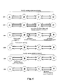
- Fig.1 is a flowchart of the method of the present invention, specifically comprising the following steps:
- the control plane of the head node stores the route information of the whole service path during the service establishing process, and other nodes store their local inputting port identifier and local outputting port identifier and local time slot information of the service passing through the nodes; after a service is successfully established, the head node sends an alarm monitoring to a corresponding time slot of a transmission plane of the head node according to the inputting port identifier and the outputting port identifier and the time slot information of the head node through which the service passes; at the same time, the head node sends notify message to other nodes which the service passed through according to the actual demand, and the information carried by the notify message is a "request setting alarm monitoring".
- Step 102 the intermediate node and the tall node set their own local alarm monitoring according to the requests of the head node;
- the intermediate node and the tail node of the service sends an alarm monitoring of the relevant position to the transmission plane according to the local inputting port and the local outputting port and the local time slot information stored in the node after receiving the notify message with an alarm monitoring setting request sent by the head node.
- Step 103 when the intermediate node and/or the tail node generates an alarm, notifying the head node of the alarm message which affects the service;
- the control plane of the local node sends the accordant alarm information to the head node through the notify message according to the matching of the alarm monitoring nodes (a plurality of time slots may generate a plurality alarms, but only the alarm generated by the time slot which bears service can effect the service, therefore, the alarm generated by the time slot which bears service needs to be reported), and then the information carried by the notify message is a "transmitting plane alarm reporting".
- the matching process of the alarm monitoring nodes has been included in the detailed solution scheme of the prior art, and unnecessary details will not given.
- Step 104 according to the received alarm information, the local alarm information of the head node and a protection and restoration strategy pre-configured by the head node, the head node sets a service maintenance strategy and a service maintenance operations, and notifies the service maintenance strategy to the tail node;
- the head node judges the alarm information received by the head node and the local alarm information of the head node comprehensively to determine whether there is a malfunction of the service;
- the head node in case that the malfunction of the service is determined by analyzing the alarm information comprehensively, and then the head node needs to set the service maintenance strategies of the head node and the tail node according to the service protection and restoration strategy pre-configured by the head node, including service prohibition, service permission, service deletion, service bridging, service switching, service bridging cancellation, service switching cancellation and etc; when one of the service maintenance strategy is determined to use, the head node shall immediately sends the maintenance operation strategy to the transmission plane of the head node, and at the same time, sends the relevant maintenance operation strategy to the tail node through the notify message, then the head node and the tail node together accomplish the maintenance of the service.
- the head node in case that the malfunction of the service is not determined by analyzing the alarm information comprehensively (alarming has transmission property, the outside alarm of the service may be transmitted to the inside of the service, and actually has no effect to the service, and then the service has no malfunction), and then the head node shall abandon the alarm information and stop further action.
- Step 105 the relevant maintenance operation shall be carried out according to the service maintenance strategy in the notify message after the tail node receives the notify message.
- the head node of the service needs to notify the tail node to carry out the service deletion together (by using compulsive deletion method) when the service maintenance strategy is the service deletion, and the procedure specifically comprises the following:
- the tail node initiates the service deletion to the upstream after receiving the deletion request from the head node.
- the method of the present invention also comprises: after a reboot of the head node, the head node actively Inquires the alarm information of the intermediate node and/or the tail node; the intermediate node and/or the tail node send their current alarm information to the head node according to the alarm inquiring request of the head node,
- the head node inquires the reported alarm information of the intermediate node and/or the tail node lost during reboot process using the notify message with an alarm inquiry; when receiving the alarm inquiry request from the head node, the intermediate node and/or the tall node of the service refresh the current alarm information with their transmission planes, and send the newest alarm information to the head node using the notify message with an alarm inquiry response,
- the ASON comprises four network elements A, B, C and D, and each network element comprises a control plane and a transmitting plane.
- the service channels among the network elements are connected through an optical fiber, and the control channels among the network elements are connected through Ethernet.
- network element A is the head node of the service
- B and C are the intermediate nodes
- D is the tail node of the service.
- Fig.3 is a flowchart of the first embodiment of the method of the present invention, and the procedure specifically comprises the following steps:
- Fig.4 is a flowchart of the second embodiment of the method of the present invention, and the procedure specifically comprises the following steps:
- Fig.5 is a flowchart of the third embodiment of the method of the present invention, and the procedure specifically comprises the following steps:
- Fig.6 is a flowchart of the fourth embodiment of the method of the present invention, and the procedure specifically comprises the following steps:
- the ASON network structure shown in Fig.2 is taken only as an example to describe the method of the present invention, but the person skilled in the art should know that the method of the present invention is not just limited to the structure shown in Fig.2 .
- the technical scheme of the present invention has the following three characteristics during service maintenance process when the ASON network generates an alarm:
Landscapes
- Engineering & Computer Science (AREA)
- Computer Networks & Wireless Communication (AREA)
- Signal Processing (AREA)
- Data Exchanges In Wide-Area Networks (AREA)
Abstract
Description
- The present invention relates to optical communication field, in particular to a maintenance method for the ASON (Automatic Switched Optical Network) system when service generates an alarm.
- The ASON network has a basic characteristic that a control plane takes full responsibility for handling service maintenance (including the establishment, deletion, protection and restoration of the service), i.e., the establishment of a signaling channel, the application for resources, the allocation of cross connection and so on are all managed by the control plane. In practical application, the control plane and the transmission plane are usually separated, thus when the service of the transmission plane goes wrong and generates an alarm, it is necessary for the control plane to timely and correctly obtain the alarm information, and properly carry out service maintenance, so as to reduce discontinuity or instantaneous interruption of the service, and eliminate the residual resources in the transmitting plane.
- Due to the malfunction of the service, corresponding protection switching actions need to be carried out simultaneously at the head node and the tail node, while the present alarm information needs to be transmitted to the head node via a plurality of service nodes node by node during transmission. When the head node sends a service maintenance request to the tail node, it has also to pass through a plurality of service nodes node by node, Such a node-by-node transmitting method takes a long time, which usually causes the discontinuity or instantaneous interruption of the service. Further, when a certain node goes wrong on the service path, it Is possible that some nodes on the service path can not receive the service maintenance request sent by the head node, and thus the transmission resources between the intermediate node and the tail node can not be effectively released, thereby causing the formation of residual connection.
- The present invention provides a maintenance method for automatic switched optical network system when service generates an alarm to solve the problems of slow transmission of alarm information, discontinuity or instantaneous interruption of the service, formation of residual connection in the prior art.
- A maintenance method for automatic switched optical network system when service generates an alarm, which comprises:
- Step A: after a service is successfully established, a head node setting a local alarm monitoring and respectively requesting an intermediate node and a tail node to set an alarm monitoring; and the intermediate node and the tail node setting their own local alarm monitoring according to the requests of the head node;
- Step B: when the intermediate node and/or the tail node generates an alarm, notifying the head node of the alarm information which affects the service;
- Step C: according to the received alarm information, the local alarm information of the head node and a protection and restoration strategy pre-configured by the head node, the head node setting a service maintenance strategy and a service maintenance operation, and notifying the service maintenance strategy to the tail node;
- Step D: t the head node and the tail node carrying out corresponding maintenance operation according to the service maintenance strategy. Further, step A specifically comprises:
- Step A1: the control plane of the head node storing the route information of the whole service path during the service establishing process; and the intermediate node and the tail node storing their local inputting port identifier, local outputting port identifier and local time slot information of the service passing through the intermediate node and the tail node;
- Step A2: after establishing the service successfully, the head node sending an alarm monitoring to a corresponding time slot of a transmission plane of the head node according to the inputting port identifier, the outputting port identifier and the time slot information of the head node through which the service passes; and at the same time, the head node requesting the intermediate node and the tail node to set an alarm monitoring using a notify message with an alarm monitoring setting request;
- Step A3: the intermediate node and the tall node sending an alarm monitoring to corresponding time slots of their transmission planes according to the inputting port identifier, the outputting port identifier and the time slot information of the service passing through the intermediate node and the tail nod.
- Further, step B specifically comprises:
- When the intermediate node or the tail node generates an alarm, their control planes sending the alarm information which affects the service to the head node using the notify message with a transmission plane alarm report according to the matching of the alarm monitoring nodes.
- Further, step C specifically comprises:
- Step C1: the head node judging whether the service has a malfunction according to the received alarm information of the matching monitoring nodes and the local alarm information of the head node;
- Step C2: when it is judged that the service has a malfunction, the head node setting the service maintenance strategy for the head node and the tail node according to the protection and restoration strategy pre-configured by the head node;
- Step C3: the head node sending the service maintenance strategy to the transmission plane of the head node, and transmitting the notify message with the service maintenance strategy to the tail node.
- The service maintenance strategy set by the head node at least comprises one of the following strategies: service prohibition, service permission, service deletion, service bridging, service switching, service bridging cancellation, and service switching cancellation.
- Further, when the service maintenance strategy is the service deletion, step D comprises:
- Step D1: when a management plane sends a service deletion request, the head node finding that the service still has an alarm according to the stored alarm information, initiating the deletion to the downstream, and at the same time, requesting the tail node, using the notify message with an service deletion request, to initiate the service deletion together with the head node;
- Step D2: the tail node initiating the service deletion to the upstream after receiving the deletion request from the head node.
- Further, the method also comprises:
- Step E: after a reboot of the head node, the head node actively inquiring the alarm information of the intermediate node and/or the tail node; the intermediate node and/or the tail node sending their current alarm information to the head node according to the alarm inquiring request of the head node.
- Further, step E specifically comprises:
- Step E1: when the head node reboots itself, the head node Inquiring the reported alarm information of the intermediate node and/or the tail node lost during reboot process using the notify message with an alarm inquiry;
- Step E2: when receiving the alarm inquiry request from the head node, the intermediate node and/or the tail node of the service refreshing the current alarm information with their transmission planes, and sending the newest alarm information to the head node using the notify message with an alarm inquiry response.
- To sum up, the maintenance method for automatic switched optical network system when service generates an alarm carries out node-to-node communication between any nodes of the service using notify message, and different nodes carry out corresponding service maintenance operations according to the different information carried by the received notify message, thereby achieving the purposes of rapid transmission of the alarm information, reduction of the discontinuity or instantaneous interruption of the service, and alleviation of the formation of residual connection of the transmission resources.
-
- Fig.1 is
- a flowchart of the method of the present invention;
- Fig.2
- is a structure view of the ASON network of the first to the fourth embodiments of the method of the present invention;
- Fig.3
- is a flowchart of the first embodiment of the method of the present invention;
- Fig.4
- is a flowchart of the second embodiment of the method of the present invention;
- Fig.5
- is a flowchart of the third embodiment of the method of the present invention:
- Fig.6
- is a flowchart of the fourth embodiment of the method of the present invention.
- The method of the present invention will be described in detail with reference to the drawings.
- The core of the method of the present invention is to carry out node-to-node communication between any nodes of the service using the notify message of the RSVP (Resource Reservation Protocol), and different nodes carry out corresponding service maintenance operations according to different information carried in the received notify message.
- As shown in
Fig.1, Fig.1 is a flowchart of the method of the present invention, specifically comprising the following steps: - Step 101: after a service is successfully established, a head node sets a local alarm monitoring and respectively requests an intermediate node and a tail node to set an alarm monitoring;
- In particular, the control plane of the head node stores the route information of the whole service path during the service establishing process, and other nodes store their local inputting port identifier and local outputting port identifier and local time slot information of the service passing through the nodes; after a service is successfully established, the head node sends an alarm monitoring to a corresponding time slot of a transmission plane of the head node according to the inputting port identifier and the outputting port identifier and the time slot information of the head node through which the service passes; at the same time, the head node sends notify message to other nodes which the service passed through according to the actual demand, and the information carried by the notify message is a "request setting alarm monitoring".
- Step 102: the intermediate node and the tall node set their own local alarm monitoring according to the requests of the head node;
- In particular, the intermediate node and the tail node of the service sends an alarm monitoring of the relevant position to the transmission plane according to the local inputting port and the local outputting port and the local time slot information stored in the node after receiving the notify message with an alarm monitoring setting request sent by the head node.
- Step 103: when the intermediate node and/or the tail node generates an alarm, notifying the head node of the alarm message which affects the service;
- In particular, when the intermediate node or the tail node generates an alarm, the control plane of the local node sends the accordant alarm information to the head node through the notify message according to the matching of the alarm monitoring nodes (a plurality of time slots may generate a plurality alarms, but only the alarm generated by the time slot which bears service can effect the service, therefore, the alarm generated by the time slot which bears service needs to be reported), and then the information carried by the notify message is a "transmitting plane alarm reporting". The matching process of the alarm monitoring nodes has been included in the detailed solution scheme of the prior art, and unnecessary details will not given.
- Step 104: according to the received alarm information, the local alarm information of the head node and a protection and restoration strategy pre-configured by the head node, the head node sets a service maintenance strategy and a service maintenance operations, and notifies the service maintenance strategy to the tail node;
- In particular, the head node judges the alarm information received by the head node and the local alarm information of the head node comprehensively to determine whether there is a malfunction of the service;
- 104-1: in case that the malfunction of the service is determined by analyzing the alarm information comprehensively, and then the head node needs to set the service maintenance strategies of the head node and the tail node according to the service protection and restoration strategy pre-configured by the head node, including service prohibition, service permission, service deletion, service bridging, service switching, service bridging cancellation, service switching cancellation and etc; when one of the service maintenance strategy is determined to use, the head node shall immediately sends the maintenance operation strategy to the transmission plane of the head node, and at the same time, sends the relevant maintenance operation strategy to the tail node through the notify message, then the head node and the tail node together accomplish the maintenance of the service.
- 104-2: in case that the malfunction of the service is not determined by analyzing the alarm information comprehensively (alarming has transmission property, the outside alarm of the service may be transmitted to the inside of the service, and actually has no effect to the service, and then the service has no malfunction), and then the head node shall abandon the alarm information and stop further action.
- Step 105: the relevant maintenance operation shall be carried out according to the service maintenance strategy in the notify message after the tail node receives the notify message.
- Wherein, the head node of the service needs to notify the tail node to carry out the service deletion together (by using compulsive deletion method) when the service maintenance strategy is the service deletion, and the procedure specifically comprises the following:
- When a management plane sends a service deletion request, the head node finds that the service still has an alarm according to the stored alarm information, initiates the deletion to the downstream, and at the same time, requests the tail node, using the notify message with an service deletion request, to initiate the service deletion together with the head node.
- The tail node initiates the service deletion to the upstream after receiving the deletion request from the head node.
- The method of the present invention also comprises: after a reboot of the head node, the head node actively Inquires the alarm information of the intermediate node and/or the tail node; the intermediate node and/or the tail node send their current alarm information to the head node according to the alarm inquiring request of the head node,
- In particular, when the head node reboots itself, the head node inquires the reported alarm information of the intermediate node and/or the tail node lost during reboot process using the notify message with an alarm inquiry; when receiving the alarm inquiry request from the head node, the intermediate node and/or the tall node of the service refresh the current alarm information with their transmission planes, and send the newest alarm information to the head node using the notify message with an alarm inquiry response,
- The present invention will be described in detail hereinafter by instances in order to make the purposes, technical scheme and advantages of the present invention clear, but will not be taken as the limitation of the present invention.
- Constructing an ASON network shown in the
Fig.2 , the ASON comprises four network elements A, B, C and D, and each network element comprises a control plane and a transmitting plane. The service channels among the network elements are connected through an optical fiber, and the control channels among the network elements are connected through Ethernet. Wherein, network element A is the head node of the service; B and C are the intermediate nodes; and D is the tail node of the service. There are two connections among the four nodes, one is a working connection of the service, and the other one is a protection connection. Normally, the service bears on the working connection. - As shown in
Fig.3 which is a flowchart of the first embodiment of the method of the present invention, and the procedure specifically comprises the following steps: - Step 301: after a service is successfully established, node A sets an local alarm monitoring and respectively informs nodes B, C and D to set their own local alarm monitoring; nodes B, C and D respectively set their own local alarm monitoring according to the request of node A;
- Step 302: No.1 optical port of node B detects multiplex section alarm information on the receiving direction when the fiber of the working connection passed by node B disconnects on the receiving direction;
- Step 303: the transmission plane of node B reports the alarm to the local control plane; the local control plane of the node B sends the multiplex alarm information to node A through notify message after the multiplex alarm is determined as the alarm which affects the service by matching;
- Step 304: node A determines the malfunction of the working connection after receiving the multiplex alarm information of node B; due to the protection connection of the service, node A initiates the switching action of the service, and at the same time, sends the notify message to node D to inform node D to carry out switching action;
- Step 305: node D sends service switching order to the local transmission plane after node D received the switching notify message sent by node A to carry out the service switching;
- Now, the service protection is successfully restored.
- As shown in
Fig.4 which is a flowchart of the second embodiment of the method of the present invention, and the procedure specifically comprises the following steps: - Step 401: after a service is successfully established, node A sets an local alarm monitoring and respectively informs nodes B, C and D to set their own local alarm monitoring; nodes B, C and D respectively set their own local alarm monitoring according to the request of node A;
- Step 402: No.1 VC4 of No.1 optical port of the working connection of node A generates a channel alarm;
- Step 403: the transmission plane of node A reports the channel alarm to the control plane; whether the channel alarm is transmitted from the outside of the connection shall be determined after node A analyzes comprehensively; therefore node A inquires the tail node through the notify message to determine whether the channel alarm exists outside the connection or not;
- Step 404: node D receives the alarm inquiry request of node A and requests the local transmission plane to refresh No.1 VC4 of No.1 optical port to determine the existing of the alarm;
- Step 405: after node D receives an alarm information outside of the connection section reported by the transmission plane (namely the alarm information is caused by the malfunction outside the connection), node D sends the alarm information outside the connection section to node A through notify message;
- Step 406: node A receives the alarm information outside the connection section reported by node D; now two conditions exist: if the outside channel alarm does not exist, which means the malfunction occurred in the inside of the connection, and then node A shall start the service protection restoration process with the procedure same as
step 304 to 305; if the outside channel alarm exists, which means the malfunction occurred in the outside of the connection, and the service protection restoration action has no need to start. - As shown in
Fig.5 which is a flowchart of the third embodiment of the method of the present invention, and the procedure specifically comprises the following steps: - Step 501: after a service is successfully established, node A sets an local alarm monitoring and respectively informs nodes B, C and D to set their own local alarm monitoring; nodes B, C and D respectively set their own local alarm monitoring according to the request of node A;
- Step 502: the control plane of node A restarts, and at the same time, No.1 VC4 of No.1 optical port of node D generates a channel alarm;
- Step 503: node A is not able to receive the alarm information reported by node D because of node A does not start;
- Step 504: node A initiatively inquires the alarm information from node D through notify message after node A restarts;
- Step 505: node D requests the local transmission plane of the node D to refresh the current alarm information of the node D after received the inquiry request of node A, and sends the alarm information reported by the transmission plane to node A through notify message;
- Step 506: node A receives the alarm information reported by node D and judges the working connection as malfunction from analysis, and then node A shall start the service protection restoration process with the procedure same as
step 304 to 305. - As shown in
Fig.6 which is a flowchart of the fourth embodiment of the method of the present invention, and the procedure specifically comprises the following steps: - Step 601: after a service is successfully established, node A sets an local alarm monitoring and respectively informs nodes B, C and D to set their own local alarm monitoring; nodes B, C and D respectively set their own local alarm monitoring according to the request of node A;
- Step 602: the transmission plane and the control plane of node C both has no power and can not carry out normal operation;
- Step 603: the multiplex section alarm information can be detected on No. 1 and No.2 optical ports of node B on the receiving direction and No.1 and No.2 optical ports of node D;
- Step 604: the transmission planes of nodes B and D respectively reported the multiplex section alarm information to their own local control plane, and nodes B and D send the multiplex section alarm information to node A through the notify message after being matched by the control planes of nodes B and D.
- Step 605: the working connection and the protection connection both are determined as malfunction after node A received the multiplex section alarm information of nodes B and D; if the management plane sends the order to delete the whole service, node A shall send RSVP PathTear (one deletion message of RSVP protocol) message to downstream to carry out deletion service, and at the same time, sends notify message to inform node D to carry out the service deletion action;
- Step 606: node D sends RSVP PathErr (one delete message of PSVP protocol) message to node C to carry out service deletion after node D receives the service deletion request message sent by node A;
- So far, the transmission resources at nodes A, B and D are effectively released, thereby reducing the formation of the residual connection.
- Here, the ASON network structure shown in
Fig.2 is taken only as an example to describe the method of the present invention, but the person skilled in the art should know that the method of the present invention is not just limited to the structure shown inFig.2 . - To sum up, the technical scheme of the present invention has the following three characteristics during service maintenance process when the ASON network generates an alarm:
- Timeliness: the notify message is directly sent from the source to the destination, and no intervention or parsing is needed at the intermediate node, therefore the transmission of maintenance information through node-to-node manner among nodes are very rapid.
- Rationality: protection switching action needs to be carried out at the head node and the tail node simultaneously when the service has a malfunction; due to the timeliness character of the transmission of the notify message, the head node and the tail node can carry out the corresponding maintenance operation almost at the same time, thereby greatly reducing the discontinuity or instantaneous interruption of the service;
- Effectiveness: the head node and the tail node initiate the service deletion at the same time due to the notify message, which effectively solves the problems that some nodes on the service path can not receive the deletion request sent by the head node when a node on the service path goes wrong, thereby greatly reducing the formation of the residual connection of the transmission resources.
- The descriptions above are only preferable embodiments of the present invention, which are not used to restrict the present invention. For those skilled in the art, the present invention may have various changes and variations. Any amendments, equivalent substitutions, improvements etc. within the sprit and principle of the present invention are all concluded in the scope of protection of the present invention. Therefore, the protection scope of the present invention should be subject to the protection scope of the claims.
Claims (8)
- A maintenance method for the Automatic Switched Optical Network, ASON, system when service generates an alarm, characterized by, comprising:Step A: after a service is successfully established, a head node setting a local alarm monitoring and respectively requesting an intermediate node and a tail node to set an alarm monitoring; and the intermediate node and the tail node setting their own local alarm monitoring according to the requests of the head node;Step B: when the intermediate node and/or the tail node generates an alarm, notifying the head node of the alarm information which affects the service;Step C: according to the received alarm information, the local alarm information of the head node and a protection and restoration strategy pre-configured by the head node, the head node setting a service maintenance strategy and a service maintenance operation, and notifying the service maintenance strategy to the tail node;Step D: the head node and the tail node carrying out corresponding maintenance operation according to the service maintenance strategy.
- The maintenance method according to Claim 1, characterized in that step A comprises:Step A1; the control plane of the head node storing the route information of the whole service path during the service establishing process; and the intermediate node and the tail node storing their local inputting port identifier, local outputting port identifier and local time slot information of the service passing through the intermediate node and the tall node;Step A2: after establishing the service successfully, the head node sending an alarm monitoring to a corresponding time slot of a transmission plane of the head node according to the inputting port identifier, the outputting port identifier and the time slot information of the head node through which the service passes; and at the same time, the head node requesting the intermediate node and the tail node to set an alarm monitoring using a notify message with an alarm monitoring setting request;Step A3: the intermediate node and the tail node sending an alarm monitoring to corresponding time slots of their transmission planes according to the inputting port identifier, the outputting port identifier and the time slot information of the service passing through the intermediate node and the tail node.
- The maintenance method according to Claim 1, characterized in that step B comprises:when the intermediate node or the tail node generates an alarm, their control planes sending the alarm information which affects the service to the head node using the notify message with a transmission plane alarm report according to the matching of the alarm monitoring nodes.
- The maintenance method according to Claim 1, characterized in that step C comprises:Step C1: the head node judging whether the service has a malfunction according to the received alarm information of the matching monitoring nodes and the local alarm information of the head node;Step C2: when it is judged that the service has a malfunction, the head node setting the service maintenance strategy for the head node and the tail node according to the protection and restoration strategy pre-configured by the head node;Step C3: the head node sending the service maintenance strategy to the transmission plane of the head node, and transmitting the notify message with the service maintenance strategy to the tall node.
- The maintenance method according to Claim 1, characterized in that the service maintenance strategy set by the head node at least comprises one of the following strategies: service prohibition, service permission, service deletion, service bridging, service switching, service bridging cancellation, and service switching cancellation.
- The maintenance method according to Claim 5, characterized in that when the service maintenance strategy is the service deletion, step D comprises:Step D1: when a management plane sends a service deletion request, the head node finding that the service still has an alarm according to the stored alarm information, initiating the deletion to the downstream, and at the same time, requesting the tail node, using the notify message with an service deletion request, to initiate the service deletion together with the head node;Step D2: the tail node Initiating the service deletion to the upstream after receiving the deletion request from the head node.
- The maintenance method according to any of Claims 1 to 6, characterized by, further comprising:Step E: after a reboot of the head node, the head node actively inquiring the alarm information of the Intermediate node and/or the tail node;
the intermediate node and/or the tail node sending their current alarm information to the head node according to the alarm inquiring request of the head node. - The maintenance method according to Claim 7, characterized in that step E comprises:Step E1: when the head node reboots itself, the head node inquiring the reported alarm information of the intermediate node and/or the tail node lost during reboot process using the notify message with an alarm inquiry;Step E2: when receiving the alarm inquiry request from the head node, the intermediate node and/or the tail node of the service refreshing the current alarm information with their transmission planes, and sending the newest alarm information to the head node using the notify message with an alarm inquiry response,
Applications Claiming Priority (2)
| Application Number | Priority Date | Filing Date | Title |
|---|---|---|---|
| CN200710165205.5A CN100589416C (en) | 2007-10-30 | 2007-10-30 | A maintenance method when a service generates an alarm in an automatic switching optical network system |
| PCT/CN2008/000141 WO2009055995A1 (en) | 2007-10-30 | 2008-01-18 | Maintaining method for automatic switched optical network system when operation engenders alarm |
Publications (3)
| Publication Number | Publication Date |
|---|---|
| EP2216939A1 true EP2216939A1 (en) | 2010-08-11 |
| EP2216939A4 EP2216939A4 (en) | 2014-08-06 |
| EP2216939B1 EP2216939B1 (en) | 2019-05-01 |
Family
ID=39250795
Family Applications (1)
| Application Number | Title | Priority Date | Filing Date |
|---|---|---|---|
| EP08700690.4A Active EP2216939B1 (en) | 2007-10-30 | 2008-01-18 | Maintaining method for automatic switched optical network system when operation engenders alarm |
Country Status (3)
| Country | Link |
|---|---|
| EP (1) | EP2216939B1 (en) |
| CN (1) | CN100589416C (en) |
| WO (1) | WO2009055995A1 (en) |
Families Citing this family (10)
| Publication number | Priority date | Publication date | Assignee | Title |
|---|---|---|---|---|
| CN101360008B (en) * | 2008-08-25 | 2013-03-20 | 中兴通讯股份有限公司 | Method for transmitting alarm on transmission plane when alarm generated by service |
| CN101515827B (en) * | 2009-03-31 | 2011-12-07 | 中兴通讯股份有限公司 | Method for business wrong link resistance wrong in an automatic switched optical network and system thereof |
| CN101583055B (en) * | 2009-05-27 | 2013-01-16 | 中兴通讯股份有限公司 | Method and system for maintaining Ethernet private line service in ASON network |
| CN101646107A (en) * | 2009-08-14 | 2010-02-10 | 中兴通讯股份有限公司 | Method, device and system for restoring service connection and node equipment |
| CN101834710B (en) * | 2010-04-30 | 2014-02-05 | 中兴通讯股份有限公司 | Method and system for controlling protection switching in plane protection group of automatic switch optical network (ASON) |
| CN102480653A (en) * | 2010-11-30 | 2012-05-30 | 中兴通讯股份有限公司 | Method and system for service activation after automatic switching optical network node restart |
| CN102546361A (en) * | 2010-12-17 | 2012-07-04 | 中兴通讯股份有限公司 | Method and device for notifying invalidation of transport plane |
| CN105991311A (en) * | 2015-01-30 | 2016-10-05 | 中兴通讯股份有限公司 | Optical transport network (OTN) device alarm processing method and device |
| CN116094581A (en) * | 2021-11-08 | 2023-05-09 | 株洲变流技术国家工程研究中心有限公司 | Communication network IO acquisition expansion method and system |
| CN114567542B (en) * | 2022-02-16 | 2023-09-15 | 烽火通信科技股份有限公司 | Hard pipeline dedicated line hop-by-hop service detection method, device, equipment and storage medium |
Family Cites Families (5)
| Publication number | Priority date | Publication date | Assignee | Title |
|---|---|---|---|---|
| EP1489784A1 (en) * | 2003-06-16 | 2004-12-22 | Alcatel | Restoration in an automatically switched optical transport network |
| CN100550764C (en) * | 2005-04-30 | 2009-10-14 | 中兴通讯股份有限公司 | A Quick Restoration Method for Automatically Switched Optical Networks |
| ES2335019T3 (en) * | 2005-05-23 | 2010-03-18 | Alcatel Lucent | EXTENSION OF RSVP PROTOCOL TO SUPPORT OAM CONFIGURATION. |
| CN100395994C (en) * | 2005-06-23 | 2008-06-18 | 华为技术有限公司 | Method of Handling Channel Faults in Automatic Switched Optical Networks |
| CN100446467C (en) * | 2005-07-15 | 2008-12-24 | 华为技术有限公司 | Recovery methods for link failures |
-
2007
- 2007-10-30 CN CN200710165205.5A patent/CN100589416C/en not_active Expired - Fee Related
-
2008
- 2008-01-18 EP EP08700690.4A patent/EP2216939B1/en active Active
- 2008-01-18 WO PCT/CN2008/000141 patent/WO2009055995A1/en not_active Ceased
Also Published As
| Publication number | Publication date |
|---|---|
| EP2216939A4 (en) | 2014-08-06 |
| CN101150444A (en) | 2008-03-26 |
| WO2009055995A1 (en) | 2009-05-07 |
| EP2216939B1 (en) | 2019-05-01 |
| CN100589416C (en) | 2010-02-10 |
Similar Documents
| Publication | Publication Date | Title |
|---|---|---|
| EP2216939B1 (en) | Maintaining method for automatic switched optical network system when operation engenders alarm | |
| US6414595B1 (en) | Method and system for processing alarm objects in a communications network | |
| US7313736B2 (en) | Method and apparatus for aggregating alarms and faults of a communications network | |
| Papadimitriou et al. | Analysis of generalized multi-protocol label switching (GMPLS)-based recovery mechanisms (including protection and restoration) | |
| EP2458797A1 (en) | Method, device and system for updating ring network topology information | |
| US7949011B2 (en) | Method and apparatus for controlling link aggregation | |
| CN1866806B (en) | Method for realizing shared grid network recovery | |
| CN103098425A (en) | Communication network system and method of configuring communication network | |
| US20100128611A1 (en) | Transmitting apparatus, alarm control method, and computer product | |
| US20160204976A1 (en) | Identifying the absence and presence of a ring protection link owner node in an ethernet network | |
| US20080205262A1 (en) | Node controller and node system | |
| EP1887733B2 (en) | A method for processing network resource, a network unit in an intelligent optical network thereof | |
| WO2007128176A1 (en) | A service switching method and the network node thereof | |
| US6775236B1 (en) | Method and system for determining and suppressing sympathetic faults of a communications network | |
| US7782892B2 (en) | Method and an apparatus for consistency verification of traffic engineering link timeslot status | |
| CN113169939A (en) | Method, network device and system for establishing service path | |
| CN119136084A (en) | A trunk optical fiber protection method, device, equipment and readable storage medium | |
| EP2704382B1 (en) | Method for managing services in a generalized-multi-protocol label switching, GMPLS, controlled network | |
| CN100382534C (en) | Detection method for protection switching failure of bidirectional multiplex section ring network in intelligent optical network | |
| CN104618257A (en) | Traffic control method, optical network unit (ONU) and optical line terminal (OLT) device | |
| JP2011142505A (en) | Pon system, optical line terminal and optical network unit of the same, and oam link state determination method | |
| US7742403B2 (en) | Deadlock detection in a telecommunication network | |
| JP2006135945A (en) | Path setup unit, path setup system and path setup method therefor | |
| EP2654241B1 (en) | Method and system for realizing loopback control through control plane | |
| CN117956325A (en) | A method and device for preventing accidental deletion of services in an automatic switching optical network |
Legal Events
| Date | Code | Title | Description |
|---|---|---|---|
| PUAI | Public reference made under article 153(3) epc to a published international application that has entered the european phase |
Free format text: ORIGINAL CODE: 0009012 |
|
| 17P | Request for examination filed |
Effective date: 20100528 |
|
| AK | Designated contracting states |
Kind code of ref document: A1 Designated state(s): AT BE BG CH CY CZ DE DK EE ES FI FR GB GR HR HU IE IS IT LI LT LU LV MC MT NL NO PL PT RO SE SI SK TR |
|
| AX | Request for extension of the european patent |
Extension state: AL BA MK RS |
|
| DAX | Request for extension of the european patent (deleted) | ||
| A4 | Supplementary search report drawn up and despatched |
Effective date: 20140708 |
|
| RIC1 | Information provided on ipc code assigned before grant |
Ipc: H04L 12/703 20130101ALN20140702BHEP Ipc: H04L 12/707 20130101ALN20140702BHEP Ipc: H04L 12/24 20060101AFI20140702BHEP Ipc: H04Q 11/00 20060101ALI20140702BHEP |
|
| STAA | Information on the status of an ep patent application or granted ep patent |
Free format text: STATUS: EXAMINATION IS IN PROGRESS |
|
| 17Q | First examination report despatched |
Effective date: 20170720 |
|
| GRAP | Despatch of communication of intention to grant a patent |
Free format text: ORIGINAL CODE: EPIDOSNIGR1 |
|
| STAA | Information on the status of an ep patent application or granted ep patent |
Free format text: STATUS: GRANT OF PATENT IS INTENDED |
|
| RIC1 | Information provided on ipc code assigned before grant |
Ipc: H04L 12/24 20060101AFI20180815BHEP Ipc: H04Q 11/00 20060101ALI20180815BHEP Ipc: H04Q 3/00 20060101ALI20180815BHEP Ipc: H04L 12/703 20130101ALN20180815BHEP Ipc: H04L 12/707 20130101ALN20180815BHEP |
|
| RIC1 | Information provided on ipc code assigned before grant |
Ipc: H04L 12/707 20130101ALN20180817BHEP Ipc: H04Q 3/00 20060101ALI20180817BHEP Ipc: H04Q 11/00 20060101ALI20180817BHEP Ipc: H04L 12/703 20130101ALN20180817BHEP Ipc: H04L 12/24 20060101AFI20180817BHEP |
|
| INTG | Intention to grant announced |
Effective date: 20180911 |
|
| GRAS | Grant fee paid |
Free format text: ORIGINAL CODE: EPIDOSNIGR3 |
|
| GRAA | (expected) grant |
Free format text: ORIGINAL CODE: 0009210 |
|
| STAA | Information on the status of an ep patent application or granted ep patent |
Free format text: STATUS: THE PATENT HAS BEEN GRANTED |
|
| AK | Designated contracting states |
Kind code of ref document: B1 Designated state(s): AT BE BG CH CY CZ DE DK EE ES FI FR GB GR HR HU IE IS IT LI LT LU LV MC MT NL NO PL PT RO SE SI SK TR |
|
| REG | Reference to a national code |
Ref country code: GB Ref legal event code: FG4D |
|
| REG | Reference to a national code |
Ref country code: CH Ref legal event code: EP Ref country code: AT Ref legal event code: REF Ref document number: 1128396 Country of ref document: AT Kind code of ref document: T Effective date: 20190515 |
|
| REG | Reference to a national code |
Ref country code: DE Ref legal event code: R096 Ref document number: 602008059899 Country of ref document: DE |
|
| REG | Reference to a national code |
Ref country code: IE Ref legal event code: FG4D |
|
| REG | Reference to a national code |
Ref country code: NL Ref legal event code: MP Effective date: 20190501 |
|
| REG | Reference to a national code |
Ref country code: LT Ref legal event code: MG4D |
|
| PG25 | Lapsed in a contracting state [announced via postgrant information from national office to epo] |
Ref country code: LT Free format text: LAPSE BECAUSE OF FAILURE TO SUBMIT A TRANSLATION OF THE DESCRIPTION OR TO PAY THE FEE WITHIN THE PRESCRIBED TIME-LIMIT Effective date: 20190501 Ref country code: ES Free format text: LAPSE BECAUSE OF FAILURE TO SUBMIT A TRANSLATION OF THE DESCRIPTION OR TO PAY THE FEE WITHIN THE PRESCRIBED TIME-LIMIT Effective date: 20190501 Ref country code: NL Free format text: LAPSE BECAUSE OF FAILURE TO SUBMIT A TRANSLATION OF THE DESCRIPTION OR TO PAY THE FEE WITHIN THE PRESCRIBED TIME-LIMIT Effective date: 20190501 Ref country code: SE Free format text: LAPSE BECAUSE OF FAILURE TO SUBMIT A TRANSLATION OF THE DESCRIPTION OR TO PAY THE FEE WITHIN THE PRESCRIBED TIME-LIMIT Effective date: 20190501 Ref country code: HR Free format text: LAPSE BECAUSE OF FAILURE TO SUBMIT A TRANSLATION OF THE DESCRIPTION OR TO PAY THE FEE WITHIN THE PRESCRIBED TIME-LIMIT Effective date: 20190501 Ref country code: NO Free format text: LAPSE BECAUSE OF FAILURE TO SUBMIT A TRANSLATION OF THE DESCRIPTION OR TO PAY THE FEE WITHIN THE PRESCRIBED TIME-LIMIT Effective date: 20190801 Ref country code: PT Free format text: LAPSE BECAUSE OF FAILURE TO SUBMIT A TRANSLATION OF THE DESCRIPTION OR TO PAY THE FEE WITHIN THE PRESCRIBED TIME-LIMIT Effective date: 20190901 Ref country code: FI Free format text: LAPSE BECAUSE OF FAILURE TO SUBMIT A TRANSLATION OF THE DESCRIPTION OR TO PAY THE FEE WITHIN THE PRESCRIBED TIME-LIMIT Effective date: 20190501 |
|
| PG25 | Lapsed in a contracting state [announced via postgrant information from national office to epo] |
Ref country code: LV Free format text: LAPSE BECAUSE OF FAILURE TO SUBMIT A TRANSLATION OF THE DESCRIPTION OR TO PAY THE FEE WITHIN THE PRESCRIBED TIME-LIMIT Effective date: 20190501 Ref country code: GR Free format text: LAPSE BECAUSE OF FAILURE TO SUBMIT A TRANSLATION OF THE DESCRIPTION OR TO PAY THE FEE WITHIN THE PRESCRIBED TIME-LIMIT Effective date: 20190802 Ref country code: BG Free format text: LAPSE BECAUSE OF FAILURE TO SUBMIT A TRANSLATION OF THE DESCRIPTION OR TO PAY THE FEE WITHIN THE PRESCRIBED TIME-LIMIT Effective date: 20190801 |
|
| REG | Reference to a national code |
Ref country code: AT Ref legal event code: MK05 Ref document number: 1128396 Country of ref document: AT Kind code of ref document: T Effective date: 20190501 |
|
| PG25 | Lapsed in a contracting state [announced via postgrant information from national office to epo] |
Ref country code: IS Free format text: LAPSE BECAUSE OF FAILURE TO SUBMIT A TRANSLATION OF THE DESCRIPTION OR TO PAY THE FEE WITHIN THE PRESCRIBED TIME-LIMIT Effective date: 20190901 |
|
| PG25 | Lapsed in a contracting state [announced via postgrant information from national office to epo] |
Ref country code: RO Free format text: LAPSE BECAUSE OF FAILURE TO SUBMIT A TRANSLATION OF THE DESCRIPTION OR TO PAY THE FEE WITHIN THE PRESCRIBED TIME-LIMIT Effective date: 20190501 Ref country code: CZ Free format text: LAPSE BECAUSE OF FAILURE TO SUBMIT A TRANSLATION OF THE DESCRIPTION OR TO PAY THE FEE WITHIN THE PRESCRIBED TIME-LIMIT Effective date: 20190501 Ref country code: SK Free format text: LAPSE BECAUSE OF FAILURE TO SUBMIT A TRANSLATION OF THE DESCRIPTION OR TO PAY THE FEE WITHIN THE PRESCRIBED TIME-LIMIT Effective date: 20190501 Ref country code: DK Free format text: LAPSE BECAUSE OF FAILURE TO SUBMIT A TRANSLATION OF THE DESCRIPTION OR TO PAY THE FEE WITHIN THE PRESCRIBED TIME-LIMIT Effective date: 20190501 Ref country code: AT Free format text: LAPSE BECAUSE OF FAILURE TO SUBMIT A TRANSLATION OF THE DESCRIPTION OR TO PAY THE FEE WITHIN THE PRESCRIBED TIME-LIMIT Effective date: 20190501 Ref country code: EE Free format text: LAPSE BECAUSE OF FAILURE TO SUBMIT A TRANSLATION OF THE DESCRIPTION OR TO PAY THE FEE WITHIN THE PRESCRIBED TIME-LIMIT Effective date: 20190501 |
|
| REG | Reference to a national code |
Ref country code: DE Ref legal event code: R097 Ref document number: 602008059899 Country of ref document: DE |
|
| PG25 | Lapsed in a contracting state [announced via postgrant information from national office to epo] |
Ref country code: IT Free format text: LAPSE BECAUSE OF FAILURE TO SUBMIT A TRANSLATION OF THE DESCRIPTION OR TO PAY THE FEE WITHIN THE PRESCRIBED TIME-LIMIT Effective date: 20190501 |
|
| PLBE | No opposition filed within time limit |
Free format text: ORIGINAL CODE: 0009261 |
|
| STAA | Information on the status of an ep patent application or granted ep patent |
Free format text: STATUS: NO OPPOSITION FILED WITHIN TIME LIMIT |
|
| PG25 | Lapsed in a contracting state [announced via postgrant information from national office to epo] |
Ref country code: TR Free format text: LAPSE BECAUSE OF FAILURE TO SUBMIT A TRANSLATION OF THE DESCRIPTION OR TO PAY THE FEE WITHIN THE PRESCRIBED TIME-LIMIT Effective date: 20190501 |
|
| 26N | No opposition filed |
Effective date: 20200204 |
|
| PG25 | Lapsed in a contracting state [announced via postgrant information from national office to epo] |
Ref country code: PL Free format text: LAPSE BECAUSE OF FAILURE TO SUBMIT A TRANSLATION OF THE DESCRIPTION OR TO PAY THE FEE WITHIN THE PRESCRIBED TIME-LIMIT Effective date: 20190501 |
|
| PG25 | Lapsed in a contracting state [announced via postgrant information from national office to epo] |
Ref country code: SI Free format text: LAPSE BECAUSE OF FAILURE TO SUBMIT A TRANSLATION OF THE DESCRIPTION OR TO PAY THE FEE WITHIN THE PRESCRIBED TIME-LIMIT Effective date: 20190501 |
|
| PG25 | Lapsed in a contracting state [announced via postgrant information from national office to epo] |
Ref country code: MC Free format text: LAPSE BECAUSE OF FAILURE TO SUBMIT A TRANSLATION OF THE DESCRIPTION OR TO PAY THE FEE WITHIN THE PRESCRIBED TIME-LIMIT Effective date: 20190501 |
|
| REG | Reference to a national code |
Ref country code: CH Ref legal event code: PL |
|
| GBPC | Gb: european patent ceased through non-payment of renewal fee |
Effective date: 20200118 |
|
| REG | Reference to a national code |
Ref country code: BE Ref legal event code: MM Effective date: 20200131 |
|
| PG25 | Lapsed in a contracting state [announced via postgrant information from national office to epo] |
Ref country code: GB Free format text: LAPSE BECAUSE OF NON-PAYMENT OF DUE FEES Effective date: 20200118 Ref country code: LU Free format text: LAPSE BECAUSE OF NON-PAYMENT OF DUE FEES Effective date: 20200118 |
|
| PG25 | Lapsed in a contracting state [announced via postgrant information from national office to epo] |
Ref country code: BE Free format text: LAPSE BECAUSE OF NON-PAYMENT OF DUE FEES Effective date: 20200131 Ref country code: CH Free format text: LAPSE BECAUSE OF NON-PAYMENT OF DUE FEES Effective date: 20200131 Ref country code: LI Free format text: LAPSE BECAUSE OF NON-PAYMENT OF DUE FEES Effective date: 20200131 |
|
| PG25 | Lapsed in a contracting state [announced via postgrant information from national office to epo] |
Ref country code: IE Free format text: LAPSE BECAUSE OF NON-PAYMENT OF DUE FEES Effective date: 20200118 |
|
| REG | Reference to a national code |
Ref country code: DE Ref legal event code: R079 Ref document number: 602008059899 Country of ref document: DE Free format text: PREVIOUS MAIN CLASS: H04L0012240000 Ipc: H04L0041000000 |
|
| PG25 | Lapsed in a contracting state [announced via postgrant information from national office to epo] |
Ref country code: MT Free format text: LAPSE BECAUSE OF FAILURE TO SUBMIT A TRANSLATION OF THE DESCRIPTION OR TO PAY THE FEE WITHIN THE PRESCRIBED TIME-LIMIT Effective date: 20190501 Ref country code: CY Free format text: LAPSE BECAUSE OF FAILURE TO SUBMIT A TRANSLATION OF THE DESCRIPTION OR TO PAY THE FEE WITHIN THE PRESCRIBED TIME-LIMIT Effective date: 20190501 |
|
| PGFP | Annual fee paid to national office [announced via postgrant information from national office to epo] |
Ref country code: FR Payment date: 20251208 Year of fee payment: 19 |
|
| PGFP | Annual fee paid to national office [announced via postgrant information from national office to epo] |
Ref country code: DE Payment date: 20251203 Year of fee payment: 19 |