EP2216841A1 - Pouch-type lithium secondary battery - Google Patents
Pouch-type lithium secondary battery Download PDFInfo
- Publication number
- EP2216841A1 EP2216841A1 EP10250026A EP10250026A EP2216841A1 EP 2216841 A1 EP2216841 A1 EP 2216841A1 EP 10250026 A EP10250026 A EP 10250026A EP 10250026 A EP10250026 A EP 10250026A EP 2216841 A1 EP2216841 A1 EP 2216841A1
- Authority
- EP
- European Patent Office
- Prior art keywords
- tab
- electrode tab
- variable
- electrode
- pouch
- Prior art date
- Legal status (The legal status is an assumption and is not a legal conclusion. Google has not performed a legal analysis and makes no representation as to the accuracy of the status listed.)
- Granted
Links
Images



Classifications
-
- H—ELECTRICITY
- H01—ELECTRIC ELEMENTS
- H01M—PROCESSES OR MEANS, e.g. BATTERIES, FOR THE DIRECT CONVERSION OF CHEMICAL ENERGY INTO ELECTRICAL ENERGY
- H01M10/00—Secondary cells; Manufacture thereof
- H01M10/36—Accumulators not provided for in groups H01M10/05-H01M10/34
-
- H—ELECTRICITY
- H01—ELECTRIC ELEMENTS
- H01M—PROCESSES OR MEANS, e.g. BATTERIES, FOR THE DIRECT CONVERSION OF CHEMICAL ENERGY INTO ELECTRICAL ENERGY
- H01M50/00—Constructional details or processes of manufacture of the non-active parts of electrochemical cells other than fuel cells, e.g. hybrid cells
- H01M50/10—Primary casings; Jackets or wrappings
- H01M50/172—Arrangements of electric connectors penetrating the casing
- H01M50/174—Arrangements of electric connectors penetrating the casing adapted for the shape of the cells
- H01M50/178—Arrangements of electric connectors penetrating the casing adapted for the shape of the cells for pouch or flexible bag cells
-
- H—ELECTRICITY
- H01—ELECTRIC ELEMENTS
- H01M—PROCESSES OR MEANS, e.g. BATTERIES, FOR THE DIRECT CONVERSION OF CHEMICAL ENERGY INTO ELECTRICAL ENERGY
- H01M50/00—Constructional details or processes of manufacture of the non-active parts of electrochemical cells other than fuel cells, e.g. hybrid cells
- H01M50/50—Current conducting connections for cells or batteries
- H01M50/531—Electrode connections inside a battery casing
- H01M50/533—Electrode connections inside a battery casing characterised by the shape of the leads or tabs
-
- H—ELECTRICITY
- H01—ELECTRIC ELEMENTS
- H01M—PROCESSES OR MEANS, e.g. BATTERIES, FOR THE DIRECT CONVERSION OF CHEMICAL ENERGY INTO ELECTRICAL ENERGY
- H01M50/00—Constructional details or processes of manufacture of the non-active parts of electrochemical cells other than fuel cells, e.g. hybrid cells
- H01M50/50—Current conducting connections for cells or batteries
- H01M50/531—Electrode connections inside a battery casing
- H01M50/534—Electrode connections inside a battery casing characterised by the material of the leads or tabs
-
- H—ELECTRICITY
- H01—ELECTRIC ELEMENTS
- H01M—PROCESSES OR MEANS, e.g. BATTERIES, FOR THE DIRECT CONVERSION OF CHEMICAL ENERGY INTO ELECTRICAL ENERGY
- H01M50/00—Constructional details or processes of manufacture of the non-active parts of electrochemical cells other than fuel cells, e.g. hybrid cells
- H01M50/50—Current conducting connections for cells or batteries
- H01M50/543—Terminals
- H01M50/547—Terminals characterised by the disposition of the terminals on the cells
- H01M50/55—Terminals characterised by the disposition of the terminals on the cells on the same side of the cell
-
- H—ELECTRICITY
- H01—ELECTRIC ELEMENTS
- H01M—PROCESSES OR MEANS, e.g. BATTERIES, FOR THE DIRECT CONVERSION OF CHEMICAL ENERGY INTO ELECTRICAL ENERGY
- H01M50/00—Constructional details or processes of manufacture of the non-active parts of electrochemical cells other than fuel cells, e.g. hybrid cells
- H01M50/50—Current conducting connections for cells or batteries
- H01M50/543—Terminals
- H01M50/562—Terminals characterised by the material
-
- H—ELECTRICITY
- H01—ELECTRIC ELEMENTS
- H01M—PROCESSES OR MEANS, e.g. BATTERIES, FOR THE DIRECT CONVERSION OF CHEMICAL ENERGY INTO ELECTRICAL ENERGY
- H01M50/00—Constructional details or processes of manufacture of the non-active parts of electrochemical cells other than fuel cells, e.g. hybrid cells
- H01M50/50—Current conducting connections for cells or batteries
- H01M50/543—Terminals
- H01M50/564—Terminals characterised by their manufacturing process
- H01M50/566—Terminals characterised by their manufacturing process by welding, soldering or brazing
-
- H—ELECTRICITY
- H01—ELECTRIC ELEMENTS
- H01M—PROCESSES OR MEANS, e.g. BATTERIES, FOR THE DIRECT CONVERSION OF CHEMICAL ENERGY INTO ELECTRICAL ENERGY
- H01M10/00—Secondary cells; Manufacture thereof
- H01M10/05—Accumulators with non-aqueous electrolyte
- H01M10/052—Li-accumulators
-
- H—ELECTRICITY
- H01—ELECTRIC ELEMENTS
- H01M—PROCESSES OR MEANS, e.g. BATTERIES, FOR THE DIRECT CONVERSION OF CHEMICAL ENERGY INTO ELECTRICAL ENERGY
- H01M10/00—Secondary cells; Manufacture thereof
- H01M10/05—Accumulators with non-aqueous electrolyte
- H01M10/058—Construction or manufacture
-
- Y—GENERAL TAGGING OF NEW TECHNOLOGICAL DEVELOPMENTS; GENERAL TAGGING OF CROSS-SECTIONAL TECHNOLOGIES SPANNING OVER SEVERAL SECTIONS OF THE IPC; TECHNICAL SUBJECTS COVERED BY FORMER USPC CROSS-REFERENCE ART COLLECTIONS [XRACs] AND DIGESTS
- Y02—TECHNOLOGIES OR APPLICATIONS FOR MITIGATION OR ADAPTATION AGAINST CLIMATE CHANGE
- Y02E—REDUCTION OF GREENHOUSE GAS [GHG] EMISSIONS, RELATED TO ENERGY GENERATION, TRANSMISSION OR DISTRIBUTION
- Y02E60/00—Enabling technologies; Technologies with a potential or indirect contribution to GHG emissions mitigation
- Y02E60/10—Energy storage using batteries
-
- Y—GENERAL TAGGING OF NEW TECHNOLOGICAL DEVELOPMENTS; GENERAL TAGGING OF CROSS-SECTIONAL TECHNOLOGIES SPANNING OVER SEVERAL SECTIONS OF THE IPC; TECHNICAL SUBJECTS COVERED BY FORMER USPC CROSS-REFERENCE ART COLLECTIONS [XRACs] AND DIGESTS
- Y02—TECHNOLOGIES OR APPLICATIONS FOR MITIGATION OR ADAPTATION AGAINST CLIMATE CHANGE
- Y02P—CLIMATE CHANGE MITIGATION TECHNOLOGIES IN THE PRODUCTION OR PROCESSING OF GOODS
- Y02P70/00—Climate change mitigation technologies in the production process for final industrial or consumer products
- Y02P70/50—Manufacturing or production processes characterised by the final manufactured product
Definitions
- the present invention relates to a secondary battery. More specifically, the present invention relates to a pouch-type lithium secondary battery with easy adjustability of an electrode tab position.
- lithium secondary batteries which advantageously exhibit rapid chargeability and high energy density per unit weight due to the light nature of lithium atoms, as compared to conventional lead storage batteries, nickel-cadmium (NiCd) batteries, nickel-hydrogen batteries, nickel-zinc batteries, and the like.
- lithium secondary batteries use a non-aqueous electrolyte due to potential reactivity of lithium with moisture.
- an electrolyte may include a lithium salt-containing solid polymer or a liquid electrolyte containing a lithium salt that is dissociated in an organic solvent.
- the organic solvent in which a lithium salt is dissolved may be ethylene carbonate, propylene carbonate, other alkyl group-containing carbonates, and the like. These solvents have boiling points of 50°C or higher and very low vapor pressure at room temperature.
- Lithium secondary batteries may be categorized into two groups including lithium metal batteries and lithium ion batteries that use liquid electrolytes and lithium ion polymer batteries that use solid polymer electrolytes.
- the lithium ion polymer battery may employ a multilayer pouch composed of a metal foil layer and one or more polymer layers covering the metal foil, instead of a metal can of the lithium ion battery.
- Use of the multilayer pouch can advantageously result in significant weight reduction of a battery, as compared to use of the metal can.
- aluminum is used as a metal constituting a foil in the multilayer pouch.
- a polymer layer forming an inner layer of the pouch film protects the metal foil against attack of an electrolyte and simultaneously inhibits possible short-circuits between positive and negative electrodes and/or between electrode tabs.
- the lithium secondary batteries using such a multilayer pouch are conventionally referred to as pouch-type lithium secondary batteries.
- a positive electrode, a separator and a negative electrode are first stacked, or stacked and wound to form an electrode assembly which is then placed in a pouch. Subsequently, an upper pouch film and a lower pouch film are thermally fused to each other in open edge portions of the pouch to form a bare cell battery of a sealed pouch type.
- PCM protection circuit module
- PTC positive temperature coefficient
- a pouch-type lithium secondary battery is of a generally square or rectangular pouch shape, and first and second electrode tabs connected to an electrode assembly are drawn outward from the pouch.
- the first and second electrode tabs are always disposed at a certain distance from each other and attached to the electrode assembly.
- a battery pack recently fabricated by the pouch-type lithium secondary battery should be designed with a different spacing between the first electrode tab and the second electrode tab, depending on the kinds of electronic devices.
- the present invention has been made in view of the above problems, and it is an object of the present invention to provide a pouch-type lithium secondary battery which is fabricated to permit easy positional adjustability of electrode tabs protruding outward from a pouch.
- a pouch-type lithium secondary battery including an electrode assembly; a pouch for accommodating the electrode assembly; and a variable tab in electrical connection with one electrode tab of two electrode tabs of the electrode assembly and being parallel to the other electrode tab and being drawn outward from the pouch.
- variable tab includes a body and a bending portion which is formed by bending an end of the body.
- the electrode tab connected to the variable tab includes a tab-connecting portion which is formed by vertically bending an end of the tab.
- variable tab and the electrode tab are connected to each other by inserting the tab-connecting portion of the electrode tab into the bending portion of the variable tab.
- the bending portion of the variable tab and the tab-connecting portion of the electrode tab are welded.
- the tab-connecting portion of the electrode tab is positioned parallel to a front sealing portion of the pouch.
- the bending portion of the variable tab and the electrode tab connected thereto are positioned within a front sealing portion of the pouch.
- variable tab includes a body and a bending portion which is formed by vertically bending a portion of the body.
- the electrode tab connected to the variable tab includes a bending portion which is formed by bending an end of the electrode tab.
- variable tab and the electrode tab are connected to each other by inserting the bending portion of the variable tab into the bending portion of the electrode tab.
- the bending portion of the variable tab and the bending portion of the electrode tab are welded.
- the bending portion of the variable tab is positioned parallel to a front sealing portion of the pouch.
- the bending portion of the variable tab and the electrode tab connected thereto are positioned within a front sealing portion of the pouch.
- variable tab is formed of the same material as the electrode tab, or otherwise the variable tab is formed of an electrically conductive material.
- variable tab is connected to the electrode tab attached to an outer periphery of the electrode assembly.
- the electrode tab to which the variable tab is connected is a positive electrode tab.
- a pouch-type lithium secondary battery comprising: an electrode assembly having a first and a second electrode tab, attached thereto and extending outward from the electrode assembly in a first direction; a pouch for accommodating the electrode assembly; a variable electrode tab coupled to the first electrode tab, wherein the variable electrode tab and the first electrode tab define an engagement surface that extends for a first length in a second direction that intersects the first direction and wherein the variable electrode tab and the first electrode tab are adapted to be fixably connected to each other at different locations along the first length of the engagement surface.
- the variable electrode tab may extend in the first direction.
- a pouch-type lithium secondary battery as set out in Claim 1. Preferred features of this aspect can be found in claims 2 to 11.
- the first electrode tab may be parallel to the second electrode tab.
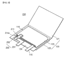
- FIG. 1 is an exploded perspective view of a pouch-type lithium secondary battery in accordance with one embodiment of the present invention
- FIG. 2 is a perspective view showing insertion of an electrode assembly into a pouch in FIG. 1
- FIG. 3 is a front view of a pouch after assembly of the pouch is complete in FIG. 2 , thus showing a reversed state of the pouch.
- a pouch-type lithium secondary battery 100 in accordance with one embodiment of the present invention includes an electrode assembly 110; a pouch 120 for accommodating the electrode assembly 110, a variable tab 130 in electrical connection with at least one tab of a positive electrode tab 114 and a negative electrode tab 115 of the electrode assembly 110.
- the electrode assembly 110 includes a positive electrode plate 111, a negative electrode plate 112, each having an electrode coating portion formed on a surface of a current collector, and an organic electrolyte-impregnated separator 113 sandwiched between the positive electrode plate 111 and the negative electrode plate 112.
- the electrode assembly 110 is fabricated by sequentially stacking the positive electrode plate 111, the negative electrode plate 112 and the separator 113 disposed therebetween, or winding the resulting stacked structure into a jelly-roll shape.
- the positive electrode tab 114 is attached to one side of the positive electrode plate 111 of the electrode assembly 110, and the negative electrode tab 115 is attached to one side of the negative electrode plate 112.
- the positive electrode tab 114 and the negative electrode tab 115 are arranged at a certain distance.
- the negative electrode tab 115 is partially protruded outward from the pouch 120, such that the electrode assembly 110 is electrically connected to the outside.
- the positive electrode tab 114 in connection with the variable tab 130 is housed in the pouch 120, and the variable tab 130 is protruded outward from the pouch 120.
- the positive electrode tab 114 and the negative electrode tab 115 are typically formed of a metal, for example, aluminum, copper or nickel. Although there is no particular limit to materials for the positive electrode tab and the negative electrode tab, the positive electrode tab 114 is preferably formed of aluminum or aluminum alloy, and the negative electrode tab 115 is preferably formed of nickel or nickel alloy.
- the pouch 120 is composed of an upper case 121 and a lower case 122 which are divided on the basis of the length direction of one side of a rectangular pouch film which is generally integrally formed.
- the lower case 122 is provided with a groove 123 for accommodation of the electrode assembly 110, by a conventional method such as pressing or the like.
- the pouch film constituting the upper and lower cases 121,122 of the pouch 120 is formed to have a stack structure where upper and lower surfaces of the pouch formed of aluminum foil are conventionally covered with a synthetic resin such as nylon, polypropylene, polyethylene, or the like.
- the pouch inside is formed of a thermally adhesive resin. Therefore, the upper case 121 and the lower case 122 are sealed to each other by heating and pressing the thermally adhesive resin coated on the inner surface of the pouch film.
- a front portion is referred to as a front sealing portion 124.
- variable tab 130 is electrically connected to at least one electrode tab of the positive electrode tab 114 or the negative electrode tab 115.
- the variable tab 130 is connected to the electrode tab attached to an outer periphery of the electrode assembly 110.
- the positive electrode tab 114 is attached to the positive electrode plate 111 in the outer periphery of the electrode assembly 110, and the variable tab 130 is connected to the positive electrode tab 114.
- the variable tab 130 includes a body 131 and a bending portion 132 formed by bending an end of the body 131.
- the positive electrode tab 114 is provided with a tab-connecting portion 114a which is formed by vertically bending an end of the tab 114.
- the bending portion 132 formed at the end of the variable tab 130 is connected to the tab-connecting portion 114a of the positive electrode tab 114. That is, connection of the variable tab 130 to the positive electrode tab 114 is made by insertion of the tab-connecting portion 114a of the positive electrode tab 114 through a gap formed between the body 131 and the bending portion 132 of the variable tab 130.
- the tab-connecting portion 114a of the positive electrode tab 114 is disposed substantially parallel to the front sealing portion 124 of the pouch.
- the tab-connecting portion 114a is formed to have a length to ensure that the variable tab 130 can move in the right and left directions with respect to the front sealing portion 124.
- variable tab 130 is formed of the same material as the positive electrode tab 114, or is formed of an electrically conductive material.
- the wound electrode assembly 110 With interposition of the separator 113 between the positive electrode plate 111 and the negative electrode plate 112, the wound electrode assembly 110 is inserted into the groove 123 on the lower case 122 of the pouch 120. Accordingly, the positive electrode tab 114 and the negative electrode tab 115 in the electrode assembly 110 are drawn outward from the lower case 122. In this connection, the positive electrode tab 114 is positioned in the front sealing portion 124 of the lower case 122, and the negative electrode tab 115 is protruded outward from the front sealing portion 124.
- variable tab 130 is connected to the tab-connecting portion 114a of the positive electrode tab 114.
- the tab-connecting portion 114a of the positive electrode tab 114 is fitted into the bending portion 132 of the variable tab 130.
- the variable tab 130 is slid in the tab-connecting portion 114a of the positive electrode tab 114. Because the variable tab 130 can be displaced in the right and left directions in correspondence to a length of the tab-connecting portion 114a, the position of the positive electrode tab 114 can be easily adjusted with respect to the original position of the positive electrode tab 114 drawn from the electrode assembly 110, depending on design conditions of the battery pack or other requirements during manufacturing processes thereof.
- variable tab 130 After the position of the variable tab 130 is adjusted on the tab-connecting portion 114a of the positive electrode tab 114, the bending portion 132 and the tab-connecting portion 114a are welded. As a result, the variable tab 130 and the positive electrode tab 114 are electrically connected, and the variable tab 130 is also fixed to the positive electrode tab 114.
- the upper case 121 of the pouch 120 is heat-sealed to the lower case 122, so the variable tab 130 is drawn outward from the pouch 120.
- the negative electrode tab 115 is also drawn outward from the pouch 120. Insulating tapes 116,117 are attached to the positive electrode tab 114 and the negative electrode tab 115 drawn through the front sealing portion 124, such that a short-circuit is prevented between the positive electrode tab 114 and the negative electrode tab 115.
- the positive electrode tab 114 is electrically connected to the variable tab 130, so the variable tab 130 serves as the positive electrode tab 114.
- a pouch-type lithium secondary battery 200 includes an electrode assembly 110; a pouch 120 for accommodating the electrode assembly 110; and a variable tab 230 in electrical connection with at least one tab of a positive electrode tab 214 and a negative electrode tab 115 of the electrode assembly 110.
- variable tab 230 is electrically connected to at least one electrode tab of the positive electrode tab 214 and the negative electrode tab 115. In another embodiment of the present invention, the variable tab 230 is connected to the positive electrode tab 214 attached to an outer periphery of the electrode assembly 110.
- the variable tab 230 includes a body 231 and a bending portion 232 which is vertically bent with respect to the body 231. An end of the positive electrode tab 214 is provided with a bending portion 214a.
- variable tab 230 is connected to the bending portion 214a of the positive electrode tab 214.
- the bending portion 232 of the variable tab 230 is inserted through the bending portion 214a of the positive electrode tab 214, such that the variable tab 230 is connected to the positive electrode tab 214.
- the bending portion 232 of the variable tab 230 is lengthwise installed parallel to the front sealing portion 124 of the pouch.
- the variable tab 230 is formed of the same material as the positive electrode tab 214, or is formed of an electrically conductive material. Although there is no particular limit to materials for the positive electrode tab and the negative electrode tab, the positive electrode tab 214 is preferably formed of aluminum or aluminum alloy, and the negative electrode tab 115 is preferably formed of nickel or nickel alloy.
- the wound electrode assembly 110 With interposition of the separator 113 between the positive electrode plate 111 and the negative electrode plate 112, the wound electrode assembly 110 is inserted into the groove 123 on the lower case 122 of the pouch 120. Accordingly, the positive electrode tab 214 and the negative electrode tab 115 in the electrode assembly 110 are drawn outward from the lower case 122. In this connection, the positive electrode tab 214 is positioned within the front sealing portion 124 of the lower case 122, and the negative electrode tab 115 is protruded outward from the front sealing portion 124.
- the variable tab 230 is connected to the positive electrode tab 214. That is, the bending portion 232 of the variable tab 230 is inserted into the bending portion 214a of the positive electrode tab 214. In this connection, the bending portion 232 of the variable tab 230 is movable in the bending portion 214a of the positive electrode tab 214. Accordingly, the bending portion 232 of the variable tab 230 is slidable with respect to the bending portion 214a of the positive electrode tab 214, so a position of the body 231 of the variable tab 230 is adjusted.
- variable tab 230 is easily adjusted with respect to the position where the positive electrode tab 214 is drawn from the electrode assembly 110.
- variable tab 230 After the position of the variable tab 230 is adjusted with respect to the positive electrode tab 214, the bending portion 232 of the variable tab 230 and the bending portion 214a of the positive electrode tab 214 are welded. As a result, the variable tab 230 and the positive electrode tab 214 are electrically connected, simultaneously with fixation of the variable tab 230 to the positive electrode tab 214.
- the upper case 121 of the pouch 120 is heat-sealed to the lower case 122, so the variable tab 230 and the negative electrode tab 115 are drawn outward from the pouch 120.
- the positive electrode tab 214 and the bending portion 232 of the variable tab 230 are positioned within the front sealing portion 124.
- the positive electrode tab 214, the bending portion 232 of the variable tab 230 and the negative electrode tab 115 are provided with the attachment of insulating tapes 116,117, so short-circuits are inhibited therebetween.
- the positive electrode tab 214 is in electrical connection with the variable tab 230, so the variable tab 230 serves as the positive electrode tab 214.
- the present invention is capable of achieving easy positional adjustability of an electrode tab protruding outward from a pouch, during a battery assembly process.
- the present invention is also capable of taking prompt measures in response to consumer demands by improving the design freedom of a battery pack particularly in a large-area battery.
Landscapes
- Chemical & Material Sciences (AREA)
- Chemical Kinetics & Catalysis (AREA)
- Electrochemistry (AREA)
- General Chemical & Material Sciences (AREA)
- Engineering & Computer Science (AREA)
- Manufacturing & Machinery (AREA)
- Connection Of Batteries Or Terminals (AREA)
- Secondary Cells (AREA)
- Sealing Battery Cases Or Jackets (AREA)
Abstract
Description
- The present invention relates to a secondary battery. More specifically, the present invention relates to a pouch-type lithium secondary battery with easy adjustability of an electrode tab position.
- With continuing recent trends towards weight reduction and higher functionalization of a variety of products including electric tools and portable wireless devices such as video cameras, cellular phones, notebook computers, and personal digital assistants (PDAs), there is increasing importance of the batteries used as a power source for these products. This interest has been matched by a great deal of research and study of these batteries.
- Particularly, intensive interest has been given to rechargeable lithium secondary batteries which advantageously exhibit rapid chargeability and high energy density per unit weight due to the light nature of lithium atoms, as compared to conventional lead storage batteries, nickel-cadmium (NiCd) batteries, nickel-hydrogen batteries, nickel-zinc batteries, and the like.
- Typically, lithium secondary batteries use a non-aqueous electrolyte due to potential reactivity of lithium with moisture. Such an electrolyte may include a lithium salt-containing solid polymer or a liquid electrolyte containing a lithium salt that is dissociated in an organic solvent. Generally, the organic solvent in which a lithium salt is dissolved may be ethylene carbonate, propylene carbonate, other alkyl group-containing carbonates, and the like. These solvents have boiling points of 50°C or higher and very low vapor pressure at room temperature.
- Lithium secondary batteries may be categorized into two groups including lithium metal batteries and lithium ion batteries that use liquid electrolytes and lithium ion polymer batteries that use solid polymer electrolytes.
- The lithium ion polymer battery may employ a multilayer pouch composed of a metal foil layer and one or more polymer layers covering the metal foil, instead of a metal can of the lithium ion battery. Use of the multilayer pouch can advantageously result in significant weight reduction of a battery, as compared to use of the metal can. Usually, aluminum is used as a metal constituting a foil in the multilayer pouch. Further, a polymer layer forming an inner layer of the pouch film protects the metal foil against attack of an electrolyte and simultaneously inhibits possible short-circuits between positive and negative electrodes and/or between electrode tabs. The lithium secondary batteries using such a multilayer pouch are conventionally referred to as pouch-type lithium secondary batteries.
- For fabrication of the pouch-type lithium secondary battery, a positive electrode, a separator and a negative electrode are first stacked, or stacked and wound to form an electrode assembly which is then placed in a pouch. Subsequently, an upper pouch film and a lower pouch film are thermally fused to each other in open edge portions of the pouch to form a bare cell battery of a sealed pouch type.
- Accessories or structures such as a protection circuit module (PCM) or a positive temperature coefficient (PTC) device are attached to the bare cell battery to form a core pack battery.
- By coupling the resulting core pack battery within a hard case, a complete hard pack battery is produced.
- Conventionally, a pouch-type lithium secondary battery is of a generally square or rectangular pouch shape, and first and second electrode tabs connected to an electrode assembly are drawn outward from the pouch. Here, the first and second electrode tabs are always disposed at a certain distance from each other and attached to the electrode assembly.
- However, a battery pack recently fabricated by the pouch-type lithium secondary battery should be designed with a different spacing between the first electrode tab and the second electrode tab, depending on the kinds of electronic devices.
- To this end, relevant modifications of battery manufacturing processes should be made depending on design conditions of battery packs to which the batteries are applied upon fabrication of the pouch-type lithium secondary batteries.
- Therefore, the present invention has been made in view of the above problems, and it is an object of the present invention to provide a pouch-type lithium secondary battery which is fabricated to permit easy positional adjustability of electrode tabs protruding outward from a pouch.
- It is another object of the present invention to provide a pouch-type lithium secondary battery which is adapted to improve the design freedom of a battery pack.
- In accordance with the present invention, the above and other objects can be accomplished by the provision of a pouch-type lithium secondary battery including an electrode assembly; a pouch for accommodating the electrode assembly; and a variable tab in electrical connection with one electrode tab of two electrode tabs of the electrode assembly and being parallel to the other electrode tab and being drawn outward from the pouch.
- Preferably, the variable tab includes a body and a bending portion which is formed by bending an end of the body.
- Preferably, the electrode tab connected to the variable tab includes a tab-connecting portion which is formed by vertically bending an end of the tab.
- Preferably, the variable tab and the electrode tab are connected to each other by inserting the tab-connecting portion of the electrode tab into the bending portion of the variable tab.
- Preferably, the bending portion of the variable tab and the tab-connecting portion of the electrode tab are welded.
- Preferably, the tab-connecting portion of the electrode tab is positioned parallel to a front sealing portion of the pouch.
- Preferably, the bending portion of the variable tab and the electrode tab connected thereto are positioned within a front sealing portion of the pouch.
- Preferably, the variable tab includes a body and a bending portion which is formed by vertically bending a portion of the body.
- Preferably, the electrode tab connected to the variable tab includes a bending portion which is formed by bending an end of the electrode tab.
- Preferably, the variable tab and the electrode tab are connected to each other by inserting the bending portion of the variable tab into the bending portion of the electrode tab.
- Preferably, the bending portion of the variable tab and the bending portion of the electrode tab are welded.
- Preferably, the bending portion of the variable tab is positioned parallel to a front sealing portion of the pouch.
- Preferably, the bending portion of the variable tab and the electrode tab connected thereto are positioned within a front sealing portion of the pouch.
- Preferably, the variable tab is formed of the same material as the electrode tab, or otherwise the variable tab is formed of an electrically conductive material.
- Preferably, the variable tab is connected to the electrode tab attached to an outer periphery of the electrode assembly.
- Preferably, the electrode tab to which the variable tab is connected is a positive electrode tab.
- According to an aspect of the invention, there is provided a pouch-type lithium secondary battery comprising: an electrode assembly having a first and a second electrode tab, attached thereto and extending outward from the electrode assembly in a first direction; a pouch for accommodating the electrode assembly; a variable electrode tab coupled to the first electrode tab, wherein the variable electrode tab and the first electrode tab define an engagement surface that extends for a first length in a second direction that intersects the first direction and wherein the variable electrode tab and the first electrode tab are adapted to be fixably connected to each other at different locations along the first length of the engagement surface. The variable electrode tab may extend in the first direction.
- According to a first aspect of the invention, there is provided a pouch-type lithium secondary battery as set out in Claim 1. Preferred features of this aspect can be found in claims 2 to 11. The first electrode tab may be parallel to the second electrode tab.
- According to a second aspect of the invention, there is provided a method of manufacturing a pouch-type lithium secondary battery as set out in Claim 12. Preferred features of this aspect can be found in claims 12 to 15.
-
-
FIG. 1 is an exploded perspective view of a pouch-type lithium secondary battery in accordance with one embodiment of the present invention; -
FIG. 2 is a perspective view showing insertion of an electrode assembly into a pouch inFIG. 1 ; -
FIG. 3 is a front view of a pouch after assembly of the pouch is complete inFIG. 2 ; -
FIG. 4 is an exploded perspective view of a pouch-type lithium secondary battery in accordance with another embodiment of the present invention; -
FIG. 5 is a perspective view showing insertion of an electrode assembly into a pouch inFIG. 4 ; and -
FIG. 6 is a front view of a pouch after assembly of the pouch is complete inFIG. 4 . - Now, preferred embodiments of the present invention will be described in more detail with reference to the accompanying drawings.
-
FIG. 1 is an exploded perspective view of a pouch-type lithium secondary battery in accordance with one embodiment of the present invention,FIG. 2 is a perspective view showing insertion of an electrode assembly into a pouch inFIG. 1 , andFIG. 3 is a front view of a pouch after assembly of the pouch is complete inFIG. 2 , thus showing a reversed state of the pouch. - Referring to
FIGS. 1 to 3 , a pouch-type lithiumsecondary battery 100 in accordance with one embodiment of the present invention includes anelectrode assembly 110; apouch 120 for accommodating theelectrode assembly 110, avariable tab 130 in electrical connection with at least one tab of apositive electrode tab 114 and anegative electrode tab 115 of theelectrode assembly 110. - The
electrode assembly 110 includes apositive electrode plate 111, anegative electrode plate 112, each having an electrode coating portion formed on a surface of a current collector, and an organic electrolyte-impregnatedseparator 113 sandwiched between thepositive electrode plate 111 and thenegative electrode plate 112. Theelectrode assembly 110 is fabricated by sequentially stacking thepositive electrode plate 111, thenegative electrode plate 112 and theseparator 113 disposed therebetween, or winding the resulting stacked structure into a jelly-roll shape. - The
positive electrode tab 114 is attached to one side of thepositive electrode plate 111 of theelectrode assembly 110, and thenegative electrode tab 115 is attached to one side of thenegative electrode plate 112. In the jelly-roll structure, thepositive electrode tab 114 and thenegative electrode tab 115 are arranged at a certain distance. Thenegative electrode tab 115 is partially protruded outward from thepouch 120, such that theelectrode assembly 110 is electrically connected to the outside. Thepositive electrode tab 114 in connection with thevariable tab 130 is housed in thepouch 120, and thevariable tab 130 is protruded outward from thepouch 120. - The
positive electrode tab 114 and thenegative electrode tab 115 are typically formed of a metal, for example, aluminum, copper or nickel. Although there is no particular limit to materials for the positive electrode tab and the negative electrode tab, thepositive electrode tab 114 is preferably formed of aluminum or aluminum alloy, and thenegative electrode tab 115 is preferably formed of nickel or nickel alloy. - The
pouch 120 is composed of anupper case 121 and alower case 122 which are divided on the basis of the length direction of one side of a rectangular pouch film which is generally integrally formed. Thelower case 122 is provided with agroove 123 for accommodation of theelectrode assembly 110, by a conventional method such as pressing or the like. The pouch film constituting the upper and lower cases 121,122 of thepouch 120 is formed to have a stack structure where upper and lower surfaces of the pouch formed of aluminum foil are conventionally covered with a synthetic resin such as nylon, polypropylene, polyethylene, or the like. Further, the pouch inside is formed of a thermally adhesive resin. Therefore, theupper case 121 and thelower case 122 are sealed to each other by heating and pressing the thermally adhesive resin coated on the inner surface of the pouch film. For convenience of illustration, out of portions where theupper case 121 and thelower case 122 are sealed, a front portion is referred to as afront sealing portion 124. - The
variable tab 130 is electrically connected to at least one electrode tab of thepositive electrode tab 114 or thenegative electrode tab 115. Preferably, thevariable tab 130 is connected to the electrode tab attached to an outer periphery of theelectrode assembly 110. - In one embodiment of the present invention, the
positive electrode tab 114 is attached to thepositive electrode plate 111 in the outer periphery of theelectrode assembly 110, and thevariable tab 130 is connected to thepositive electrode tab 114. - The
variable tab 130 includes abody 131 and a bendingportion 132 formed by bending an end of thebody 131. Thepositive electrode tab 114 is provided with a tab-connectingportion 114a which is formed by vertically bending an end of thetab 114. - Therefore, the bending
portion 132 formed at the end of thevariable tab 130 is connected to the tab-connectingportion 114a of thepositive electrode tab 114. That is, connection of thevariable tab 130 to thepositive electrode tab 114 is made by insertion of the tab-connectingportion 114a of thepositive electrode tab 114 through a gap formed between thebody 131 and the bendingportion 132 of thevariable tab 130. - The tab-connecting
portion 114a of thepositive electrode tab 114 is disposed substantially parallel to thefront sealing portion 124 of the pouch. The tab-connectingportion 114a is formed to have a length to ensure that thevariable tab 130 can move in the right and left directions with respect to thefront sealing portion 124. - The
variable tab 130 is formed of the same material as thepositive electrode tab 114, or is formed of an electrically conductive material. - Hereinafter, the operation of the pouch-type lithium secondary battery in accordance with one embodiment of the present invention as constructed above will be described.
- With interposition of the
separator 113 between thepositive electrode plate 111 and thenegative electrode plate 112, thewound electrode assembly 110 is inserted into thegroove 123 on thelower case 122 of thepouch 120. Accordingly, thepositive electrode tab 114 and thenegative electrode tab 115 in theelectrode assembly 110 are drawn outward from thelower case 122. In this connection, thepositive electrode tab 114 is positioned in thefront sealing portion 124 of thelower case 122, and thenegative electrode tab 115 is protruded outward from thefront sealing portion 124. - The
variable tab 130 is connected to the tab-connectingportion 114a of thepositive electrode tab 114. In other words, the tab-connectingportion 114a of thepositive electrode tab 114 is fitted into the bendingportion 132 of thevariable tab 130. Then, thevariable tab 130 is slid in the tab-connectingportion 114a of thepositive electrode tab 114. Because thevariable tab 130 can be displaced in the right and left directions in correspondence to a length of the tab-connectingportion 114a, the position of thepositive electrode tab 114 can be easily adjusted with respect to the original position of thepositive electrode tab 114 drawn from theelectrode assembly 110, depending on design conditions of the battery pack or other requirements during manufacturing processes thereof. - After the position of the
variable tab 130 is adjusted on the tab-connectingportion 114a of thepositive electrode tab 114, the bendingportion 132 and the tab-connectingportion 114a are welded. As a result, thevariable tab 130 and thepositive electrode tab 114 are electrically connected, and thevariable tab 130 is also fixed to thepositive electrode tab 114. - The
upper case 121 of thepouch 120 is heat-sealed to thelower case 122, so thevariable tab 130 is drawn outward from thepouch 120. In addition, thenegative electrode tab 115 is also drawn outward from thepouch 120. Insulating tapes 116,117 are attached to thepositive electrode tab 114 and thenegative electrode tab 115 drawn through thefront sealing portion 124, such that a short-circuit is prevented between thepositive electrode tab 114 and thenegative electrode tab 115. - In the asassembled pouch-type lithium secondary battery, the
positive electrode tab 114 is electrically connected to thevariable tab 130, so thevariable tab 130 serves as thepositive electrode tab 114. - Hereinafter, a pouch-type lithium secondary battery in accordance with another embodiment of the present invention will be described.
- Referring to
FIGS. 4 to 6 , a pouch-type lithiumsecondary battery 200 includes anelectrode assembly 110; apouch 120 for accommodating theelectrode assembly 110; and avariable tab 230 in electrical connection with at least one tab of apositive electrode tab 214 and anegative electrode tab 115 of theelectrode assembly 110. - Configurations of the
electrode assembly 110, thenegative electrode tab 115 and thepouch 120 are the same as those of the previous embodiment of the present invention and details thereof will be omitted herein. Like numbers refer to like elements throughout the specification and drawings. - The
variable tab 230 is electrically connected to at least one electrode tab of thepositive electrode tab 214 and thenegative electrode tab 115. In another embodiment of the present invention, thevariable tab 230 is connected to thepositive electrode tab 214 attached to an outer periphery of theelectrode assembly 110. - The
variable tab 230 includes abody 231 and a bendingportion 232 which is vertically bent with respect to thebody 231. An end of thepositive electrode tab 214 is provided with a bendingportion 214a. - The
variable tab 230 is connected to the bendingportion 214a of thepositive electrode tab 214. In other words, the bendingportion 232 of thevariable tab 230 is inserted through the bendingportion 214a of thepositive electrode tab 214, such that thevariable tab 230 is connected to thepositive electrode tab 214. The bendingportion 232 of thevariable tab 230 is lengthwise installed parallel to thefront sealing portion 124 of the pouch. - The
variable tab 230 is formed of the same material as thepositive electrode tab 214, or is formed of an electrically conductive material. Although there is no particular limit to materials for the positive electrode tab and the negative electrode tab, thepositive electrode tab 214 is preferably formed of aluminum or aluminum alloy, and thenegative electrode tab 115 is preferably formed of nickel or nickel alloy. - Hereinafter, the operation of the pouch-type lithium secondary battery in accordance with another embodiment of the present invention as constructed above will be described.
- With interposition of the
separator 113 between thepositive electrode plate 111 and thenegative electrode plate 112, thewound electrode assembly 110 is inserted into thegroove 123 on thelower case 122 of thepouch 120. Accordingly, thepositive electrode tab 214 and thenegative electrode tab 115 in theelectrode assembly 110 are drawn outward from thelower case 122. In this connection, thepositive electrode tab 214 is positioned within thefront sealing portion 124 of thelower case 122, and thenegative electrode tab 115 is protruded outward from thefront sealing portion 124. - The
variable tab 230 is connected to thepositive electrode tab 214. That is, the bendingportion 232 of thevariable tab 230 is inserted into the bendingportion 214a of thepositive electrode tab 214. In this connection, the bendingportion 232 of thevariable tab 230 is movable in the bendingportion 214a of thepositive electrode tab 214. Accordingly, the bendingportion 232 of thevariable tab 230 is slidable with respect to the bendingportion 214a of thepositive electrode tab 214, so a position of thebody 231 of thevariable tab 230 is adjusted. - In this manner, the position of the
variable tab 230 is easily adjusted with respect to the position where thepositive electrode tab 214 is drawn from theelectrode assembly 110. - After the position of the
variable tab 230 is adjusted with respect to thepositive electrode tab 214, the bendingportion 232 of thevariable tab 230 and the bendingportion 214a of thepositive electrode tab 214 are welded. As a result, thevariable tab 230 and thepositive electrode tab 214 are electrically connected, simultaneously with fixation of thevariable tab 230 to thepositive electrode tab 214. - The
upper case 121 of thepouch 120 is heat-sealed to thelower case 122, so thevariable tab 230 and thenegative electrode tab 115 are drawn outward from thepouch 120. Here, thepositive electrode tab 214 and the bendingportion 232 of thevariable tab 230 are positioned within thefront sealing portion 124. - The
positive electrode tab 214, the bendingportion 232 of thevariable tab 230 and thenegative electrode tab 115 are provided with the attachment of insulating tapes 116,117, so short-circuits are inhibited therebetween. - In the as-assembled pouch-type lithium secondary battery, the
positive electrode tab 214 is in electrical connection with thevariable tab 230, so thevariable tab 230 serves as thepositive electrode tab 214. - As described before, the present invention is capable of achieving easy positional adjustability of an electrode tab protruding outward from a pouch, during a battery assembly process.
- The present invention is also capable of taking prompt measures in response to consumer demands by improving the design freedom of a battery pack particularly in a large-area battery.
- Although the foregoing description has shown, illustrated and described various implementations and embodiments of the present invention, it will be appreciated that various modifications and changes to the form and the detail of the described embodiments may be made by those skilled in the art. Hence, the scope of the present invention should not be limited to the foregoing discussion but should be defined by the appended claims.
Claims (15)
- A pouch-type lithium secondary battery comprising:an electrode assembly having a first electrode tab and a second electrode tab;a pouch for accommodating the electrode assembly; anda variable tab in electrical connection with the first electrode tab, the variable tab extending outward from the pouch.
- A battery according to claim 1, wherein the first electrode tab extends outward from the electrode assembly in a first direction, and wherein the variable electrode tab and the first electrode tab define an engagement surface that extends for a first length in a second direction that intersects the first direction, the variable electrode tab and the first electrode tab being fixably connected to each other at a location along the first length of the engagement surface.
- A battery according to claim 2, wherein the first electrode tab includes a first member that is coupled to the electrode assembly and extends in the first direction, and a second member that extends in the second direction, and wherein the second member defines the engagement surface.
- A battery according to claim 3, wherein the variable electrode tab comprises a bent portion that extends about the engagement surface to permit movement of the variable electrode tab with respect to the engagement surface prior to the fixing of the variable electrode tab to the first electrode tab.
- A battery according to Claim 2, wherein the first electrode tab is coupled to the electrode assembly and extends in the first direction, and wherein the first electrode tab comprises a bent portion.
- A battery according to Claim 5, wherein the variable electrode tab includes a first section, that defines the engagement surface, and a second section that extends outward from the first section, wherein the bent portion of the first electrode tab extends about the engagement surface so as to allow movement therebetween of the bent portion of the first electrode tab and the variable electrode tab prior to prior to the fixing of the variable electrode tab to the first electrode tab.
- A battery according to claim 1 or 2, wherein the variable tab includes a body and a bent portion which is formed by bending an end of the body, wherein the electrode tab connected to the variable tab includes a tab-connecting portion which is formed by bending an end of the tab, wherein the variable tab and the electrode tab are connected to each other by inserting the tab-connecting portion of the first electrode tab into the bent portion of the variable tab.
- A battery according to claim 1 or 2, wherein the variable tab includes a body and a bent portion which is formed by bending a portion of the body; wherein the electrode tab connected to the variable tab includes a bent portion which is formed by bending an end of the electrode tab; wherein the variable tab and the electrode tab are connected to each other by inserting the bent portion of the variable tab into the bent portion of the electrode tab.
- A battery according to claim 2 or any claim dependent on claim 2, wherein the engagement surface is positioned parallel to a front sealing portion of the pouch.
- A battery according to claim 2 or any claim dependent on claim 2, wherein the engagement surface is positioned within a front sealing portion of the pouch.
- A battery according to any one of claims 1 to 10, wherein the variable tab is formed of the same material as the electrode tab; and/or
wherein the variable tab and the first electrode tab are welded; and/or
wherein the variable tab is formed of an electrically conductive material; and/or
the variable tab is connected to the electrode tab attached to an outer periphery of the electrode assembly; and/or
wherein the first electrode tab to which the variable tab is connected is a positive electrode tab. - A method of manufacturing a pouch-type lithium secondary battery comprising:providing an electrode assembly having a first electrode tab and a second electrode tab, the first electrode tab extending outward from the electrode assembly in a first direction;providing a pouch for accommodating the electrode assembly;coupling a variable electrode tab to the first electrode tab, wherein the variable electrode tab and the first electrode tab define an engagement surface that extends for a first length in a second direction that intersects the first direction;adjusting a relative position of the variable electrode tab and the first electrode tab so as to position the variable electrode tab at a location along the first length of the engagement surface;fixing the variable electrode tab and the first electrode tab at said location along the first length of the engagement surface.
- A method according to Claim 12, wherein the first electrode tab includes a first member that is coupled to the electrode assembly and extends in the first direction, and a second member that extends substantially perpendicular to the first direction, wherein the second member defines the engagement surface.
- A method according to Claim 13, wherein the variable electrode tab defines a bent portion that extends about the engagement surface to permit movement of the variable electrode tab with respect to the engagement surface prior to the fixing of the variable electrode tab to the first electrode tab.
- A method according to Claim 12, wherein the variable electrode tab includes a first section that that is coupled to the first electrode tab and that extends in the second direction, and a second section that extends outward from the first section in the first direction, wherein the first member defines the engagement surface.
Applications Claiming Priority (1)
| Application Number | Priority Date | Filing Date | Title |
|---|---|---|---|
| KR1020090001452A KR101023870B1 (en) | 2009-01-08 | 2009-01-08 | Pouch Type Lithium Secondary Battery |
Publications (2)
| Publication Number | Publication Date |
|---|---|
| EP2216841A1 true EP2216841A1 (en) | 2010-08-11 |
| EP2216841B1 EP2216841B1 (en) | 2016-04-20 |
Family
ID=42102698
Family Applications (1)
| Application Number | Title | Priority Date | Filing Date |
|---|---|---|---|
| EP10250026.1A Not-in-force EP2216841B1 (en) | 2009-01-08 | 2010-01-08 | Pouch-type lithium secondary battery |
Country Status (5)
| Country | Link |
|---|---|
| US (1) | US8691430B2 (en) |
| EP (1) | EP2216841B1 (en) |
| JP (1) | JP5186470B2 (en) |
| KR (1) | KR101023870B1 (en) |
| CN (1) | CN101777666A (en) |
Cited By (2)
| Publication number | Priority date | Publication date | Assignee | Title |
|---|---|---|---|---|
| EP3327827A4 (en) * | 2015-11-11 | 2018-06-27 | LG Chem, Ltd. | Battery cell comprising electrode lead having protruding extension and tab connector |
| EP3716361A4 (en) * | 2017-11-20 | 2021-07-14 | Libest Inc. | Metal tab for flexible battery |
Families Citing this family (17)
| Publication number | Priority date | Publication date | Assignee | Title |
|---|---|---|---|---|
| US8691429B2 (en) * | 2008-10-14 | 2014-04-08 | Samsung Sdi Co., Ltd. | Polymer battery pack and method for manufacturing the same |
| JP5589534B2 (en) * | 2010-04-28 | 2014-09-17 | 日産自動車株式会社 | Flat battery |
| US9095077B2 (en) | 2011-11-30 | 2015-07-28 | Apple Inc. | Graphene heat dissipators in portable electronic devices |
| KR101403388B1 (en) * | 2012-05-07 | 2014-06-03 | 주식회사 엘지화학 | Battery Cell of Irregular Structure and Battery Module Employed with the Same |
| KR20140015769A (en) * | 2012-07-24 | 2014-02-07 | 삼성에스디아이 주식회사 | Rechargable battery |
| US20140050955A1 (en) * | 2012-08-15 | 2014-02-20 | Apple Inc. | Mechanical support structure in a battery pouch |
| US20140212701A1 (en) * | 2013-01-29 | 2014-07-31 | Samsung Sdi Co., Ltd. | Battery cell |
| KR101603087B1 (en) * | 2013-03-04 | 2016-03-15 | 주식회사 엘지화학 | Battery Cell Having Improved Safety Against Internal Short |
| US9876199B2 (en) * | 2013-03-14 | 2018-01-23 | Brightvolt, Inc. | Batteries comprising a mulitlayer dielectric and sealing film and method of making the batteries |
| KR101808312B1 (en) * | 2013-09-26 | 2017-12-12 | 주식회사 엘지화학 | Secondary battery and Electrode lead assembly applied for the same |
| KR102210460B1 (en) * | 2014-04-24 | 2021-02-02 | 에스케이이노베이션 주식회사 | Battery cell assembly for secondary battery |
| KR101784743B1 (en) * | 2015-01-23 | 2017-11-06 | 삼성에스디아이 주식회사 | Rechargeable battery |
| US10095284B2 (en) * | 2016-01-29 | 2018-10-09 | Htc Corporation | Portable electronic device |
| CN208955108U (en) * | 2018-10-11 | 2019-06-07 | 宁德时代新能源科技股份有限公司 | Secondary cell and its electrode member |
| KR102848290B1 (en) * | 2019-07-16 | 2025-08-20 | 삼성전자주식회사 | Battery and electronic device having the same |
| DE102021001982A1 (en) * | 2021-04-15 | 2021-12-02 | Daimler Ag | Cell connector and method for contacting at least two galvanic cells |
| KR102733272B1 (en) | 2021-10-05 | 2024-11-25 | 삼성에스디아이 주식회사 | Secondary battery |
Citations (3)
| Publication number | Priority date | Publication date | Assignee | Title |
|---|---|---|---|---|
| US20010038938A1 (en) * | 2000-03-17 | 2001-11-08 | Tdk Corporation | Electrochemical device |
| JP2006324114A (en) * | 2005-05-18 | 2006-11-30 | Ngk Spark Plug Co Ltd | Thin battery |
| EP1901369A1 (en) | 2006-09-18 | 2008-03-19 | LG Chemical Limited | Secondary battery having electrode terminal whose position is adjustable and improved safety |
Family Cites Families (13)
| Publication number | Priority date | Publication date | Assignee | Title |
|---|---|---|---|---|
| EP0917218B1 (en) | 1997-11-05 | 2006-03-01 | Philips Consumer Communications France | A battery unit and a portable battery-operated device including such a battery unit |
| JP2001307696A (en) | 2000-04-21 | 2001-11-02 | Tookado:Kk | Battery pack |
| JP2002358947A (en) * | 2001-06-01 | 2002-12-13 | Tdk Corp | Electrochemical device |
| JP4984358B2 (en) * | 2001-07-31 | 2012-07-25 | ソニー株式会社 | Battery and battery pack |
| JP4283518B2 (en) * | 2002-10-07 | 2009-06-24 | Tdk株式会社 | Electrochemical devices |
| JP5013666B2 (en) | 2003-10-17 | 2012-08-29 | ソニー株式会社 | Battery pack using exterior film and battery pack manufacturing method |
| KR20060071813A (en) | 2004-12-22 | 2006-06-27 | 남도현 | Battery pack for mobile communication terminal and manufacturing method thereof |
| KR100857034B1 (en) | 2005-03-25 | 2008-09-05 | 주식회사 엘지화학 | Battery containing flame-retardant adhesive member |
| KR100686814B1 (en) | 2005-04-26 | 2007-02-26 | 삼성에스디아이 주식회사 | Polymer battery packs and manufacturing methods thereof |
| JP2008091036A (en) | 2006-09-29 | 2008-04-17 | Nec Tokin Corp | Battery pack |
| KR101048226B1 (en) | 2007-01-25 | 2011-07-08 | 에스케이이노베이션 주식회사 | Lithium secondary battery |
| US8691429B2 (en) | 2008-10-14 | 2014-04-08 | Samsung Sdi Co., Ltd. | Polymer battery pack and method for manufacturing the same |
| JP5470918B2 (en) * | 2009-03-05 | 2014-04-16 | 日産自動車株式会社 | Flat battery |
-
2009
- 2009-01-08 KR KR1020090001452A patent/KR101023870B1/en not_active Expired - Fee Related
- 2009-12-02 JP JP2009274835A patent/JP5186470B2/en not_active Expired - Fee Related
- 2009-12-21 US US12/643,750 patent/US8691430B2/en not_active Expired - Fee Related
- 2009-12-31 CN CN200910215254A patent/CN101777666A/en active Pending
-
2010
- 2010-01-08 EP EP10250026.1A patent/EP2216841B1/en not_active Not-in-force
Patent Citations (3)
| Publication number | Priority date | Publication date | Assignee | Title |
|---|---|---|---|---|
| US20010038938A1 (en) * | 2000-03-17 | 2001-11-08 | Tdk Corporation | Electrochemical device |
| JP2006324114A (en) * | 2005-05-18 | 2006-11-30 | Ngk Spark Plug Co Ltd | Thin battery |
| EP1901369A1 (en) | 2006-09-18 | 2008-03-19 | LG Chemical Limited | Secondary battery having electrode terminal whose position is adjustable and improved safety |
Cited By (3)
| Publication number | Priority date | Publication date | Assignee | Title |
|---|---|---|---|---|
| EP3327827A4 (en) * | 2015-11-11 | 2018-06-27 | LG Chem, Ltd. | Battery cell comprising electrode lead having protruding extension and tab connector |
| US10644298B2 (en) | 2015-11-11 | 2020-05-05 | Lg Chem, Ltd. | Battery cell comprising electrode lead having protruding extension and tab connector |
| EP3716361A4 (en) * | 2017-11-20 | 2021-07-14 | Libest Inc. | Metal tab for flexible battery |
Also Published As
| Publication number | Publication date |
|---|---|
| JP2010161066A (en) | 2010-07-22 |
| JP5186470B2 (en) | 2013-04-17 |
| US20100173193A1 (en) | 2010-07-08 |
| KR101023870B1 (en) | 2011-03-22 |
| US8691430B2 (en) | 2014-04-08 |
| EP2216841B1 (en) | 2016-04-20 |
| CN101777666A (en) | 2010-07-14 |
| KR20100082119A (en) | 2010-07-16 |
Similar Documents
| Publication | Publication Date | Title |
|---|---|---|
| EP2216841B1 (en) | Pouch-type lithium secondary battery | |
| US7201998B2 (en) | Pouch-type lithium secondary battery | |
| KR100496305B1 (en) | Pouched-type lithium secondary battery and the fabrication method thereof | |
| KR100948848B1 (en) | Battery unit and lithium secondary battery using same | |
| US10601081B2 (en) | Battery pack | |
| US8679675B2 (en) | Battery including a member configured to prevent a short circuit | |
| CN111682250A (en) | Secondary battery | |
| KR102018694B1 (en) | Rechargeable battery | |
| US20050100784A1 (en) | Laminated battery | |
| CN101615694A (en) | Electrode assembly and lithium secondary battery using the electrode assembly | |
| US9450217B2 (en) | Pouch battery and manufacturing method thereof | |
| CN101295779A (en) | Pouch type secondary battery and preparation method thereof | |
| KR101441530B1 (en) | Battery Cell of Novel Structure And Battery Pack Employed with the Same | |
| US10177351B2 (en) | Rechargeable battery | |
| KR100922742B1 (en) | Pouch type case and lithium secondary battery using same | |
| KR102637306B1 (en) | Battery pack and method for manufacturing the same | |
| US20100092860A1 (en) | Rechargeable battery | |
| KR20060027281A (en) | Pouch-type lithium secondary battery and manufacturing method thereof | |
| KR100580767B1 (en) | Pouch Type Lithium-ion Polymer Battery | |
| KR100635743B1 (en) | Secondary battery | |
| EP4181255B1 (en) | Method of manufacturing secondary battery | |
| KR100731437B1 (en) | Pouch Type Lithium Secondary Battery | |
| KR101386168B1 (en) | Rechargeable battery pack | |
| US20170069902A1 (en) | Secondary battery | |
| KR100659887B1 (en) | Manufacturing Method of Secondary Battery |
Legal Events
| Date | Code | Title | Description |
|---|---|---|---|
| PUAI | Public reference made under article 153(3) epc to a published international application that has entered the european phase |
Free format text: ORIGINAL CODE: 0009012 |
|
| 17P | Request for examination filed |
Effective date: 20100114 |
|
| AK | Designated contracting states |
Kind code of ref document: A1 Designated state(s): AT BE BG CH CY CZ DE DK EE ES FI FR GB GR HR HU IE IS IT LI LT LU LV MC MK MT NL NO PL PT RO SE SI SK SM TR |
|
| AX | Request for extension of the european patent |
Extension state: AL BA RS |
|
| 17Q | First examination report despatched |
Effective date: 20131023 |
|
| GRAP | Despatch of communication of intention to grant a patent |
Free format text: ORIGINAL CODE: EPIDOSNIGR1 |
|
| RIC1 | Information provided on ipc code assigned before grant |
Ipc: H01M 10/052 20100101ALN20150908BHEP Ipc: H01M 10/058 20100101ALN20150908BHEP Ipc: H01M 2/06 20060101ALI20150908BHEP Ipc: H01M 2/02 20060101AFI20150908BHEP Ipc: H01M 2/26 20060101ALI20150908BHEP Ipc: H01M 2/30 20060101ALI20150908BHEP |
|
| RIC1 | Information provided on ipc code assigned before grant |
Ipc: H01M 10/058 20100101ALN20150917BHEP Ipc: H01M 2/02 20060101AFI20150917BHEP Ipc: H01M 10/052 20100101ALN20150917BHEP Ipc: H01M 2/06 20060101ALI20150917BHEP Ipc: H01M 2/26 20060101ALI20150917BHEP Ipc: H01M 2/30 20060101ALI20150917BHEP |
|
| RIN1 | Information on inventor provided before grant (corrected) |
Inventor name: KIM, JOONGHEON |
|
| INTG | Intention to grant announced |
Effective date: 20150928 |
|
| GRAS | Grant fee paid |
Free format text: ORIGINAL CODE: EPIDOSNIGR3 |
|
| GRAA | (expected) grant |
Free format text: ORIGINAL CODE: 0009210 |
|
| INTG | Intention to grant announced |
Effective date: 20160225 |
|
| RIC1 | Information provided on ipc code assigned before grant |
Ipc: H01M 10/058 20100101ALN20160216BHEP Ipc: H01M 10/052 20100101ALN20160216BHEP Ipc: H01M 2/26 20060101ALI20160216BHEP Ipc: H01M 2/30 20060101ALI20160216BHEP Ipc: H01M 2/02 20060101AFI20160216BHEP Ipc: H01M 2/06 20060101ALI20160216BHEP |
|
| AK | Designated contracting states |
Kind code of ref document: B1 Designated state(s): AT BE BG CH CY CZ DE DK EE ES FI FR GB GR HR HU IE IS IT LI LT LU LV MC MK MT NL NO PL PT RO SE SI SK SM TR |
|
| REG | Reference to a national code |
Ref country code: GB Ref legal event code: FG4D |
|
| REG | Reference to a national code |
Ref country code: CH Ref legal event code: EP |
|
| REG | Reference to a national code |
Ref country code: AT Ref legal event code: REF Ref document number: 793287 Country of ref document: AT Kind code of ref document: T Effective date: 20160515 |
|
| REG | Reference to a national code |
Ref country code: IE Ref legal event code: FG4D |
|
| REG | Reference to a national code |
Ref country code: DE Ref legal event code: R096 Ref document number: 602010032428 Country of ref document: DE |
|
| REG | Reference to a national code |
Ref country code: LT Ref legal event code: MG4D |
|
| REG | Reference to a national code |
Ref country code: AT Ref legal event code: MK05 Ref document number: 793287 Country of ref document: AT Kind code of ref document: T Effective date: 20160420 |
|
| REG | Reference to a national code |
Ref country code: NL Ref legal event code: MP Effective date: 20160420 |
|
| PG25 | Lapsed in a contracting state [announced via postgrant information from national office to epo] |
Ref country code: NO Free format text: LAPSE BECAUSE OF FAILURE TO SUBMIT A TRANSLATION OF THE DESCRIPTION OR TO PAY THE FEE WITHIN THE PRESCRIBED TIME-LIMIT Effective date: 20160720 Ref country code: LT Free format text: LAPSE BECAUSE OF FAILURE TO SUBMIT A TRANSLATION OF THE DESCRIPTION OR TO PAY THE FEE WITHIN THE PRESCRIBED TIME-LIMIT Effective date: 20160420 Ref country code: NL Free format text: LAPSE BECAUSE OF FAILURE TO SUBMIT A TRANSLATION OF THE DESCRIPTION OR TO PAY THE FEE WITHIN THE PRESCRIBED TIME-LIMIT Effective date: 20160420 Ref country code: FI Free format text: LAPSE BECAUSE OF FAILURE TO SUBMIT A TRANSLATION OF THE DESCRIPTION OR TO PAY THE FEE WITHIN THE PRESCRIBED TIME-LIMIT Effective date: 20160420 Ref country code: PL Free format text: LAPSE BECAUSE OF FAILURE TO SUBMIT A TRANSLATION OF THE DESCRIPTION OR TO PAY THE FEE WITHIN THE PRESCRIBED TIME-LIMIT Effective date: 20160420 |
|
| PG25 | Lapsed in a contracting state [announced via postgrant information from national office to epo] |
Ref country code: GR Free format text: LAPSE BECAUSE OF FAILURE TO SUBMIT A TRANSLATION OF THE DESCRIPTION OR TO PAY THE FEE WITHIN THE PRESCRIBED TIME-LIMIT Effective date: 20160721 Ref country code: ES Free format text: LAPSE BECAUSE OF FAILURE TO SUBMIT A TRANSLATION OF THE DESCRIPTION OR TO PAY THE FEE WITHIN THE PRESCRIBED TIME-LIMIT Effective date: 20160420 Ref country code: HR Free format text: LAPSE BECAUSE OF FAILURE TO SUBMIT A TRANSLATION OF THE DESCRIPTION OR TO PAY THE FEE WITHIN THE PRESCRIBED TIME-LIMIT Effective date: 20160420 Ref country code: SE Free format text: LAPSE BECAUSE OF FAILURE TO SUBMIT A TRANSLATION OF THE DESCRIPTION OR TO PAY THE FEE WITHIN THE PRESCRIBED TIME-LIMIT Effective date: 20160420 Ref country code: AT Free format text: LAPSE BECAUSE OF FAILURE TO SUBMIT A TRANSLATION OF THE DESCRIPTION OR TO PAY THE FEE WITHIN THE PRESCRIBED TIME-LIMIT Effective date: 20160420 Ref country code: LV Free format text: LAPSE BECAUSE OF FAILURE TO SUBMIT A TRANSLATION OF THE DESCRIPTION OR TO PAY THE FEE WITHIN THE PRESCRIBED TIME-LIMIT Effective date: 20160420 Ref country code: PT Free format text: LAPSE BECAUSE OF FAILURE TO SUBMIT A TRANSLATION OF THE DESCRIPTION OR TO PAY THE FEE WITHIN THE PRESCRIBED TIME-LIMIT Effective date: 20160822 |
|
| PG25 | Lapsed in a contracting state [announced via postgrant information from national office to epo] |
Ref country code: BE Free format text: LAPSE BECAUSE OF FAILURE TO SUBMIT A TRANSLATION OF THE DESCRIPTION OR TO PAY THE FEE WITHIN THE PRESCRIBED TIME-LIMIT Effective date: 20160420 Ref country code: IT Free format text: LAPSE BECAUSE OF FAILURE TO SUBMIT A TRANSLATION OF THE DESCRIPTION OR TO PAY THE FEE WITHIN THE PRESCRIBED TIME-LIMIT Effective date: 20160420 |
|
| REG | Reference to a national code |
Ref country code: DE Ref legal event code: R097 Ref document number: 602010032428 Country of ref document: DE |
|
| PG25 | Lapsed in a contracting state [announced via postgrant information from national office to epo] |
Ref country code: EE Free format text: LAPSE BECAUSE OF FAILURE TO SUBMIT A TRANSLATION OF THE DESCRIPTION OR TO PAY THE FEE WITHIN THE PRESCRIBED TIME-LIMIT Effective date: 20160420 Ref country code: CZ Free format text: LAPSE BECAUSE OF FAILURE TO SUBMIT A TRANSLATION OF THE DESCRIPTION OR TO PAY THE FEE WITHIN THE PRESCRIBED TIME-LIMIT Effective date: 20160420 Ref country code: DK Free format text: LAPSE BECAUSE OF FAILURE TO SUBMIT A TRANSLATION OF THE DESCRIPTION OR TO PAY THE FEE WITHIN THE PRESCRIBED TIME-LIMIT Effective date: 20160420 Ref country code: RO Free format text: LAPSE BECAUSE OF FAILURE TO SUBMIT A TRANSLATION OF THE DESCRIPTION OR TO PAY THE FEE WITHIN THE PRESCRIBED TIME-LIMIT Effective date: 20160420 Ref country code: SK Free format text: LAPSE BECAUSE OF FAILURE TO SUBMIT A TRANSLATION OF THE DESCRIPTION OR TO PAY THE FEE WITHIN THE PRESCRIBED TIME-LIMIT Effective date: 20160420 |
|
| PLBE | No opposition filed within time limit |
Free format text: ORIGINAL CODE: 0009261 |
|
| STAA | Information on the status of an ep patent application or granted ep patent |
Free format text: STATUS: NO OPPOSITION FILED WITHIN TIME LIMIT |
|
| PG25 | Lapsed in a contracting state [announced via postgrant information from national office to epo] |
Ref country code: SM Free format text: LAPSE BECAUSE OF FAILURE TO SUBMIT A TRANSLATION OF THE DESCRIPTION OR TO PAY THE FEE WITHIN THE PRESCRIBED TIME-LIMIT Effective date: 20160420 |
|
| 26N | No opposition filed |
Effective date: 20170123 |
|
| PG25 | Lapsed in a contracting state [announced via postgrant information from national office to epo] |
Ref country code: SI Free format text: LAPSE BECAUSE OF FAILURE TO SUBMIT A TRANSLATION OF THE DESCRIPTION OR TO PAY THE FEE WITHIN THE PRESCRIBED TIME-LIMIT Effective date: 20160420 |
|
| REG | Reference to a national code |
Ref country code: DE Ref legal event code: R119 Ref document number: 602010032428 Country of ref document: DE |
|
| REG | Reference to a national code |
Ref country code: CH Ref legal event code: PL |
|
| GBPC | Gb: european patent ceased through non-payment of renewal fee |
Effective date: 20170108 |
|
| PG25 | Lapsed in a contracting state [announced via postgrant information from national office to epo] |
Ref country code: MC Free format text: LAPSE BECAUSE OF FAILURE TO SUBMIT A TRANSLATION OF THE DESCRIPTION OR TO PAY THE FEE WITHIN THE PRESCRIBED TIME-LIMIT Effective date: 20160420 |
|
| REG | Reference to a national code |
Ref country code: FR Ref legal event code: ST Effective date: 20170929 |
|
| PG25 | Lapsed in a contracting state [announced via postgrant information from national office to epo] |
Ref country code: CH Free format text: LAPSE BECAUSE OF NON-PAYMENT OF DUE FEES Effective date: 20170131 Ref country code: FR Free format text: LAPSE BECAUSE OF NON-PAYMENT OF DUE FEES Effective date: 20170131 Ref country code: LI Free format text: LAPSE BECAUSE OF NON-PAYMENT OF DUE FEES Effective date: 20170131 |
|
| REG | Reference to a national code |
Ref country code: IE Ref legal event code: MM4A |
|
| PG25 | Lapsed in a contracting state [announced via postgrant information from national office to epo] |
Ref country code: GB Free format text: LAPSE BECAUSE OF NON-PAYMENT OF DUE FEES Effective date: 20170108 Ref country code: LU Free format text: LAPSE BECAUSE OF NON-PAYMENT OF DUE FEES Effective date: 20170108 Ref country code: DE Free format text: LAPSE BECAUSE OF NON-PAYMENT OF DUE FEES Effective date: 20170801 |
|
| PG25 | Lapsed in a contracting state [announced via postgrant information from national office to epo] |
Ref country code: IE Free format text: LAPSE BECAUSE OF NON-PAYMENT OF DUE FEES Effective date: 20170108 |
|
| PG25 | Lapsed in a contracting state [announced via postgrant information from national office to epo] |
Ref country code: MT Free format text: LAPSE BECAUSE OF NON-PAYMENT OF DUE FEES Effective date: 20170108 |
|
| PG25 | Lapsed in a contracting state [announced via postgrant information from national office to epo] |
Ref country code: HU Free format text: LAPSE BECAUSE OF FAILURE TO SUBMIT A TRANSLATION OF THE DESCRIPTION OR TO PAY THE FEE WITHIN THE PRESCRIBED TIME-LIMIT; INVALID AB INITIO Effective date: 20100108 |
|
| PG25 | Lapsed in a contracting state [announced via postgrant information from national office to epo] |
Ref country code: BG Free format text: LAPSE BECAUSE OF FAILURE TO SUBMIT A TRANSLATION OF THE DESCRIPTION OR TO PAY THE FEE WITHIN THE PRESCRIBED TIME-LIMIT Effective date: 20160420 |
|
| PG25 | Lapsed in a contracting state [announced via postgrant information from national office to epo] |
Ref country code: CY Free format text: LAPSE BECAUSE OF NON-PAYMENT OF DUE FEES Effective date: 20160420 |
|
| PG25 | Lapsed in a contracting state [announced via postgrant information from national office to epo] |
Ref country code: MK Free format text: LAPSE BECAUSE OF FAILURE TO SUBMIT A TRANSLATION OF THE DESCRIPTION OR TO PAY THE FEE WITHIN THE PRESCRIBED TIME-LIMIT Effective date: 20160420 |
|
| PG25 | Lapsed in a contracting state [announced via postgrant information from national office to epo] |
Ref country code: TR Free format text: LAPSE BECAUSE OF FAILURE TO SUBMIT A TRANSLATION OF THE DESCRIPTION OR TO PAY THE FEE WITHIN THE PRESCRIBED TIME-LIMIT Effective date: 20160420 |
|
| PG25 | Lapsed in a contracting state [announced via postgrant information from national office to epo] |
Ref country code: IS Free format text: LAPSE BECAUSE OF FAILURE TO SUBMIT A TRANSLATION OF THE DESCRIPTION OR TO PAY THE FEE WITHIN THE PRESCRIBED TIME-LIMIT Effective date: 20160820 |