EP2216535A1 - Piston engine and sterling engine - Google Patents
Piston engine and sterling engine Download PDFInfo
- Publication number
- EP2216535A1 EP2216535A1 EP08854837A EP08854837A EP2216535A1 EP 2216535 A1 EP2216535 A1 EP 2216535A1 EP 08854837 A EP08854837 A EP 08854837A EP 08854837 A EP08854837 A EP 08854837A EP 2216535 A1 EP2216535 A1 EP 2216535A1
- Authority
- EP
- European Patent Office
- Prior art keywords
- sleeves
- heater
- temperature side
- working fluid
- sleeve
- Prior art date
- Legal status (The legal status is an assumption and is not a legal conclusion. Google has not performed a legal analysis and makes no representation as to the accuracy of the status listed.)
- Granted
Links
Images



Classifications
-
- F—MECHANICAL ENGINEERING; LIGHTING; HEATING; WEAPONS; BLASTING
- F02—COMBUSTION ENGINES; HOT-GAS OR COMBUSTION-PRODUCT ENGINE PLANTS
- F02G—HOT GAS OR COMBUSTION-PRODUCT POSITIVE-DISPLACEMENT ENGINE PLANTS; USE OF WASTE HEAT OF COMBUSTION ENGINES; NOT OTHERWISE PROVIDED FOR
- F02G5/00—Profiting from waste heat of combustion engines, not otherwise provided for
- F02G5/02—Profiting from waste heat of exhaust gases
-
- F—MECHANICAL ENGINEERING; LIGHTING; HEATING; WEAPONS; BLASTING
- F02—COMBUSTION ENGINES; HOT-GAS OR COMBUSTION-PRODUCT ENGINE PLANTS
- F02G—HOT GAS OR COMBUSTION-PRODUCT POSITIVE-DISPLACEMENT ENGINE PLANTS; USE OF WASTE HEAT OF COMBUSTION ENGINES; NOT OTHERWISE PROVIDED FOR
- F02G1/00—Hot gas positive-displacement engine plants
- F02G1/04—Hot gas positive-displacement engine plants of closed-cycle type
- F02G1/043—Hot gas positive-displacement engine plants of closed-cycle type the engine being operated by expansion and contraction of a mass of working gas which is heated and cooled in one of a plurality of constantly communicating expansible chambers, e.g. Stirling cycle type engines
- F02G1/053—Component parts or details
-
- F—MECHANICAL ENGINEERING; LIGHTING; HEATING; WEAPONS; BLASTING
- F02—COMBUSTION ENGINES; HOT-GAS OR COMBUSTION-PRODUCT ENGINE PLANTS
- F02G—HOT GAS OR COMBUSTION-PRODUCT POSITIVE-DISPLACEMENT ENGINE PLANTS; USE OF WASTE HEAT OF COMBUSTION ENGINES; NOT OTHERWISE PROVIDED FOR
- F02G2253/00—Seals
- F02G2253/02—Reciprocating piston seals
-
- Y—GENERAL TAGGING OF NEW TECHNOLOGICAL DEVELOPMENTS; GENERAL TAGGING OF CROSS-SECTIONAL TECHNOLOGIES SPANNING OVER SEVERAL SECTIONS OF THE IPC; TECHNICAL SUBJECTS COVERED BY FORMER USPC CROSS-REFERENCE ART COLLECTIONS [XRACs] AND DIGESTS
- Y02—TECHNOLOGIES OR APPLICATIONS FOR MITIGATION OR ADAPTATION AGAINST CLIMATE CHANGE
- Y02T—CLIMATE CHANGE MITIGATION TECHNOLOGIES RELATED TO TRANSPORTATION
- Y02T10/00—Road transport of goods or passengers
- Y02T10/10—Internal combustion engine [ICE] based vehicles
- Y02T10/12—Improving ICE efficiencies
Definitions
- the present invention relates to a piston engine and a Stirling engine in which pistons make reciprocating motions in cylinders without using piston rings and a lubricant.
- Patent Document 1 discloses a Stirling engine in which gas bearings are interposed between pistons and cylinders as well as the pistons are supported by approximately linear mechanisms and reciprocatingly moved.
- Patent Document 1 Japanese Patent Application Laid-open No. 2005-106009 ([0013], FIGS. 1 and 5 )
- a piston engine includes cylinders including sleeves into which a working fluid flows and thermally connected to a heater, the working fluid being passed through the heater that heats the working fluid; pistons that makes reciprocating motions in the sleeves by a pressure change of the working fluid; and gas bearings formed between inner peripheral surfaces of the sleeves and outer peripheral surfaces of the pistons, the inner peripheral surfaces of the sleeves and the outer peripheral surfaces of the pistons being disposed in confrontation with each other.
- a piston engine includes cylinders including sleeves into which a working fluid flows and thermally connected to a heater, and outer shells disposed outside of the sleeves, the working fluid being passed through the heater that heats the working fluid; pistons that makes reciprocating motions in the sleeves by a pressure change of the working fluid; and gas bearings formed between inner peripheral surfaces of the sleeves and outer peripheral surfaces of the pistons, the inner peripheral surfaces of the sleeves and the outer peripheral surfaces of the pistons being disposed in confrontation with each other.
- a piston engine includes cylinders composed of a double structure including sleeves into which a working fluid flows and outer shells disposed outside of the sleeves, the working fluid being passed through the heater that heats the working fluid; pistons that makes reciprocating motions in the sleeves by a pressure change of the working fluid; and gas bearings formed between inner peripheral surfaces of the sleeves and outer peripheral surfaces of the pistons, the inner peripheral surfaces of the sleeves and the outer peripheral surfaces of the pistons being disposed in confrontation with each other.
- portions where at least the gas bearings can be formed have a double structure in which the outer shells are disposed outside of the sleeves.
- the sleeves and the outer shells are composed of a different structural member, respectively, and sleeve support portions are disposed to ends of the sleeves on the heater side; and the sleeves are attached to the outer shells by attaching the sleeve support portions to one end of the outer shells, and the sleeves are coupled with the heater.
- the sleeves are not in contact with the outer shells through metal in portions where the gas bearings are formed.
- the sleeves and the outer shells are disposed at predetermined intervals.
- the outer shells support a force which acts on the cylinders and is in a direction parallel to a center axis of the cylinder, and the sleeves receive a pressure of the working fluid existing in the sleeves.
- a Stirling engine includes a heat exchanger including a heater that heats a working fluid, a regenerator that is connected to the heater and through which the working fluid passes, and a cooler that is connected to the regenerator and cools the working fluid; cylinders including sleeves into which the working fluid passed through the heater flows and thermally connected to the heater, and outer shells disposed outside of the sleeves; pistons that make reciprocating motions in the sleeves by a pressure change of the working fluid; and gas bearings that are formed between inner peripheral surfaces of the sleeves and outer peripheral surfaces of the pistons, the inner peripheral surfaces of the sleeves and the outer peripheral surfaces of the pistons being disposed in confrontation with each other.
- portions where at least the gas bearings can be formed have a double structure in which the outer shells are disposed outside of the sleeves.
- the pistons are supported by approximately linear mechanisms.
- the Stirling engine in the Stirling engine, it is preferred that when the Stirling engine includes a plurality of cylinders and a plurality of pistons, at least one of the cylinders thermally connects between the heater and the sleeves; and at least the one of the cylinders is composed of a double structure having the sleeve and an outer shell disposed outside of the sleeve.
- the present invention can reduce a possibility that the pistons are in contact with the cylinders.
- a Stirling engine that is an external combustion engine will be explained below as an example of a piston engine.
- the piston engine is preferably the external combustion engine in the embodiment as described above, the piston engine is not limited to the external combustion engine.
- a target from which exhaust heat is recovered is not limited to the internal combustion engine.
- the present invention can be also applied to a case in which exhaust heat from, for example, a factory, a plant, and a power generation facility is recovered.
- the embodiment is a piston engine having gas bearings interposed between pistons and cylinders and has a feature in that the embodiment includes sleeves into which a working fluid of the piston engine, which has passed through a heater for heating the working fluid, flows and the sleeves are thermally connected to the heater. Further, in the embodiment, outer shells are disposed outside of the sleeves, and the cylinders are configured in a double structure of the sleeves and the outer shells.
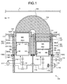
- FIG. 1 is a sectional view illustrating a configuration of the Stirling engine as the piston engine according to the embodiment.
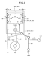
- FIG. 2 is an explanatory view illustrating a configuration example of the gas bearing included in the Stirling engine as the piston engine according to the embodiment and a support structure of the piston.
- a Stirling engine 100 as the piston engine according to the embodiment is a so-called ⁇ type parallel two-cylinder Stirling engine.
- the parallel two-cylinder is configured such that two cylinders are arranged in a direction parallel with a rotating shaft of a crank shaft 110 as an output shaft of the Stirling engine 100.
- the Stirling engine 100 disposes a heat exchanger 108 to a heater case 3 acting as a path through which an exhaust gas Ex from an internal combustion engine is caused to pass and is used as an exhaust heat recover device for recovering heat energy from the exhaust gas Ex of the internal combustion engine.
- the Stirling engine 100 includes a high temperature side piston 20H accommodated in a high temperature side cylinder 30H and a low temperature side piston 20L accommodated in a low temperature side cylinder 30L, and the high temperature side piston 20H is disposed in series with the low temperature side piston 20L.
- the heat exchanger 108 is disposed between the high temperature side cylinder 30H and the low temperature side cylinder 30L. Note that, in the following description, when the high temperature side cylinder 30H and the low temperature side cylinder 30L are not discriminated from each other, they are called a cylinder 30, and when the high temperature side piston 20H and the low temperature side piston 20L are not discriminated from each other, they are called a piston 20.
- the high temperature side cylinder 30H and the low temperature side cylinder 30L are directly or indirectly supported by and fixed to a base plate 111 as a reference member.
- the base plate 111 acts as a position reference of respective components of the Stirling engine 100. With this configuration, the relative positional accuracies of the respective components can be secured.
- the Stirling engine 100 according to the embodiment has gas bearings GB between the high temperature side cylinder 30H and the high temperature side piston 20H and between the low temperature side cylinder 30L and the low temperature side piston 20L.
- the high temperature side cylinder 30H is composed of the double structure including a sleeve 30HR as a cylindrical structural member and a cylinder block 30HB as the outer shell disposed outside of an outer peripheral portion of the sleeve 30HR.
- the sleeve 30HR has the high temperature side piston 20H disposed therein with a result that an inner peripheral surface of the sleeve 30HR and an outer peripheral surface of the high temperature side piston 20H are disposed in confrontation with each other.
- the gas bearing GB is formed between the sleeve 30HR and the high temperature side piston 20H, and the high temperature side piston 20H makes a reciprocating motion in the sleeve 30HR while being supported in the sleeve 30HR through the gas bearing GB.
- a working space (high temperature side working space) MSH in which the working fluid of the Stirling engine 100 exists, is formed in the sleeve 30HR.
- the high temperature side working space MSH is a space surrounded by an inner surface of the sleeve 30HR, an apex surface of the high temperature side piston 20H, and an end of a heater 105 connected to the high temperature side cylinder 30H.
- the working fluid of the Stirling engine 100 is air.
- the working fluid which has passed through the heater 105 for heating the working fluid, flows into the sleeve 30HR, that is, into the high temperature side working space MSH. Further, the working fluid flows into the heater 105 from the high temperature side working space MSH.
- the high temperature side piston 20H makes the reciprocating motion in the sleeve 30HR by a pressure change of the working fluid in the high temperature side working space MSH.
- the low temperature side cylinder 30L is composed of a sleeve 30LR as a cylindrical structural member and a cylinder block 30LB as the outer shell disposed outside of the outer peripheral portion of the sleeve 30LR. Note that the sleeve 30LR and the cylinder block 30LB may be composed of the same structural member without disposing the sleeve 30LR.
- the low temperature side piston 20L is disposed in the sleeve 30LR so that an inner peripheral surface of the sleeve 30LR is disposed in confrontation with an outer peripheral surface of the low temperature side piston 20L.
- the gas bearing GB is formed between the sleeve 30LR and the low temperature side piston 20L, and the low temperature side piston 20L is supported in the sleeve 30LR by the gas bearing GB and makes a reciprocating motion in the sleeve 30LR.
- a working space (low temperature side working space) MSL in which the working fluid of the Stirling engine 100 exists, is formed in the sleeve 30LR.
- the low temperature side working space MSL is a space surrounded by an inner surface of the sleeve 30LR, an apex surface of the low temperature side piston 20L, and an end of a cooler 107 connected to the low temperature side cylinder 30L.
- the working fluid which has passed through the cooler 107 for cooling the working fluid, flows into the sleeve 30LR, that is, into the low temperature side working space MSL. Further, the working fluid flows into the cooler 107 from the low temperature side working space MSL.
- the low temperature side piston 20L makes a reciprocating motion in the sleeve 30LR by a pressure change of the working fluid in the low temperature side working space MSL.
- the Stirling engine 100 indirectly attaches the high temperature side cylinder 30H and the low temperature side cylinder 30L to the base plate 111 as the reference member. With this configuration, a clearance between the piston 20 and the cylinder 30 can be accurately kept by securing a position accuracy between the piston 20 and the cylinder 30 using the base plate 111. With this configuration, a function of the gas bearing GB can be sufficiently exhibited. Further, the Stirling engine 100 can be also easily assembled. Note that the high temperature side cylinder 30H and the low temperature side cylinder 30L may be directly attached to the base plate 111.
- the heat exchanger 108 which is composed of an approximately U-shaped heater (heating device) 105, a regenerator 106, and the cooler 107, is disposed between the high temperature side cylinder 30H and the low temperature side cylinder 30L.
- the heater 105 can be easily disposed also to a relatively narrow space such as an exhaust gas path of an internal combustion engine by forming the heater 105 in the approximately U-shape as described above. Further, when the high temperature side cylinder 30H and the low temperature side cylinder 30L are disposed in series as in the Stirling engine 100, the heater 105 can be relatively easily disposed in a cylindrical space such as an exhaust gas path of the internal combustion engine.
- One end of the heater 105 is disposed on the high temperature side cylinder 30H side, and the other end of the heater 105 is disposed on the regenerator 106 side.
- One end of the regenerator 106 is disposed on the heater 105 side and the other end of the regenerator 106 is disposed on the cooler 107 side, and the working fluid, which flows in from the heater 105 or the cooler 107, passes through the regenerator 106.
- One end of the cooler 107 is disposed on the regenerator 106 side, and the other end of the cooler 107 is disposed on the low temperature side cylinder 30L side.
- a heater/cylinder coupling member 120 is attached to an end of the heater 105 disposed on the high temperature side cylinder 30H side.
- the heater/cylinder coupling member 120 is composed of a good heat conductor such as metal and constitutes a part of the heater 105.
- An end of the heater/cylinder coupling member 120 opposite to a side thereof connected to the heater 105 is attached to the high temperature side cylinder 30H, and, more specifically, to the sleeve 30HR that constitutes the high temperature side cylinder 30H.
- the heater 105 is connected to the high temperature side cylinder 30H through the heater/cylinder coupling member 120. While the Stirling engine 100 is in operation, the working fluid, which has passed through the heater 105, flows into the high temperature side cylinder 30H as well as the working fluid in the high temperature side cylinder 30H flows into the heater 105.
- a cooler/cylinder coupling member 121 is attached to an end of the cooler 107 disposed on the low temperature side cylinder 30L side. An end of the cooler/cylinder coupling member 121 opposite to a side thereof connected to the cooler 107 is attached to the low temperature side cylinder 30L. With this configuration, the cooler 107 is connected to the low temperature side cylinder 30L through the cooler/cylinder coupling member 121. While the Stirling engine 100 is in operation, the working fluid, which has passed through the cooler 107, flows into the low temperature side cylinder 30L as well as the working fluid in the low temperature side cylinder 30L flows into the cooler 107.
- the heater/cylinder coupling member 120 is attached to the base plate 111 through a flange 120F expanding to an outer peripheral portion of the heater/cylinder coupling member 120.
- the high temperature side cylinder 30H is attached to the base plate 111 through the heater/cylinder coupling member 120.
- the cooler/cylinder coupling member 121 is attached to the base plate 111 through a flange 121F expanding to an outer peripheral portion of the cooler/cylinder coupling member 121.
- the low temperature side cylinder 30L is attached to the base plate 111 through the cooler/cylinder coupling member 121.
- the heater 105 heats the working fluid of the Stirling engine 100.
- the cooler 107 cools the working fluid.
- the working fluid which has passed through the heat exchanger 108, flows into and flows out from the high temperature side cylinder 30H and the low temperature side cylinder 30L.
- the working fluid is contained in the sleeve 30HR of the high temperature side cylinder 30H, in the sleeve 30LR of the low temperature side cylinder 30L, and in the heat exchanger 108, and a Stirling cycle is formed by the heat supplied from the heater 105 to thereby drive the Stirling engine 100.
- the heater 105 and the cooler 107 can be formed by bundling a plurality of tubes of a material having a high thermal conductivity and an excellent heat resistance.
- the cooler 107 may be cooled by air or by water.
- the regenerator 106 is composed of, for example, a porous heat accumulating member. Note that the configurations of the heater 105, the cooler 107, and the regenerator 106 are not limited to those exemplified above, and preferable configurations can be selected according to a heat condition of an exhaust heat recovery target, a specification of the Stirling engine 100, and the like.
- the high temperature side piston 20H and the low temperature side piston 20L are supported in the high temperature side cylinder 30H and the low temperature side cylinder 30L through the gas bearings GB. That is, this is a structure for supporting the high temperature side piston 20H and the low temperature side piston 20L in the cylinders 30H and 30L without through piston rings and without using a lubricant. With this configuration, efficiency of the Stirling engine 100 can be improved by reducing friction between the piston 20 and the cylinder 30.
- predetermined clearances tc are formed between the high temperature side piston 20H and the low temperature side piston 20L and the sleeves 30HR, 30LR as illustrated in FIG. 2 .
- the clearance tc is formed in several microns to several tens of microns around an entire periphery of the piston 20.
- the reciprocating motions of the high temperature side piston 20H and the low temperature side piston 20L are transmitted to the crank shaft 110 as an output shaft by a connecting rod 61 and converted to a rotational motion by the crank shaft 110.
- the gas bearing GB has a low capability (load capability) for withstanding force in a diameter direction (lateral direction, thrust direction) of the piston 20, it is preferable to set side force Fs of the piston 20 to substantially 0. Accordingly, a high linear motion accuracy of the piston 20 to the axial line (center axis) of the cylinder 30 is required.
- the high temperature side piston 20H and the low temperature side piston 20L are supported by approximately linear mechanisms (for example, grasshopper mechanisms) 60 illustrated in FIG. 2 .
- the high temperature side piston 20H and the low temperature side piston 20L make approximately linear reciprocating motions by the approximately linear mechanisms 60 as well as the reciprocating motions are transmitted to the crank shaft 110 through the connecting rod 61.
- the reciprocating motions of the high temperature side piston 20H and the low temperature side piston 20L supported by the approximately linear mechanisms 60 are converted to a rotating motion by the crank shaft 110, and the rotating motion is taken out as an output of the Stirling engine 100. More specifically, the Stirling engine 100 obtains the output by converting the reciprocating motions of the high temperature side piston 20H and the low temperature side piston 20L supported by the approximately linear mechanisms 60 to the rotating motion by the crank shaft 110.
- the grasshopper mechanisms are used for the approximately linear mechanisms 60.
- the approximately linear mechanisms 60 are called grasshopper mechanisms 60 in the following description.
- Each of the grasshopper mechanisms 60 is composed of a first arm 62 having one end rotatably attached to a housing 100C of the Stirling engine 100, a second arm 63 having one end rotatably attached to the housing 100C of the Stirling engine 100 likewise, and a third arm 64 having one end rotatably coupled with an end of the connecting rod 61 and the other end rotatably coupled with the other end of the second arm 63.
- An end of the connecting rod 61 which is different from the end thereof rotatably attached to the crank shaft 110, is rotatably coupled with an end of the third arm 64.
- the other end of the first arm 62 is rotatably coupled between both the ends of the third arm 63.
- the high temperature side piston 20H and the low temperature side piston 20L can be approximately linearly reciprocated by use of the grasshopper mechanisms 60. As a result, since the side force Fs of the piston 20 becomes almost 0, the piston 20 can be sufficiently supported even by the gas bearing GB having a small load capability. Note that the approximately linear mechanism for supporting the piston 20 is not limited to the grasshopper mechanism, and a watts link and the like may be used.
- the grasshopper mechanisms 60 can obtain the same linear motion accuracy by a size smaller than that of other linear approximation mechanisms, the grasshopper mechanisms 60 are advantageous in that the Stirling engine 100 can be made compact in its entirety.
- a degree of freedom of installation can be improved when the Stirling engine 100 is compact in its entirety.
- the grasshopper mechanism 60 is advantageous to improve heat efficiency.
- the grasshopper mechanism 60 is relatively simply configured, the grasshopper mechanism 60 is advantageous in that it can be easily manufactured and assembled and can reduce also a manufacturing cost.
- the housing 100C includes a crank case 114A, the cylinder blocks 30HB, 30LB, and a housing reinforcing member 114B.
- the crank case 114A which constitutes the housing 100C of the Stirling engine 100, is filled with a gas.
- the gas is the same as the working fluid of the Stirling engine 100.
- the gas filled in the crank case 114A is pressurized by a pump 115 as a pressure adjustment unit.
- the pump 115 may be driven by, for example, an internal combustion engine as an exhaust heat recovery target of the Stirling engine 100 or may be driven by, for example, a drive means such as a motor.
- the Stirling engine 100 can obtain a higher output.
- the Stirling engine 100 is configured such that the working fluids in the high temperature side working space MSH and the low temperature side working space MSL are kept at a high pressure by pressurizing the gas filled in the crank case 114A by the Stirling engine 100 so that a larger output can be taken out from the Stirling engine 100.
- the output of the Stirling engine 100 is increased approximately in proportion to a pressure of the gas filled in the crank case 114A.
- a seal bearing 116 is attached to the crank case 114A, and the crank shaft 110 is supported by the seal bearing 116.
- the output from the crank shaft 110 is taken out to the outside of the crank case 114A through a flexible coupling 119 such as, for example, an Oldham's coupling.
- a magnetic coupling which is coupled with the crank shaft 110, may be disposed between an inside and an outside of the crank case 114A, and the output of the crank shaft 110 may be taken out to the outside of the crank case 114A through the magnetic coupling.
- the gas bearings GB are formed by blowing a gas (in the embodiment, air which is the same as the working fluid) A from gas supply openings HE formed around side peripheral portions of the high temperature side piston 20H and the low temperature side piston 20L.
- a gas in the embodiment, air which is the same as the working fluid
- FIGS. 1 and 2 a high temperature side piston internal space 20HI and a low temperature side piston internal space 20LI are formed in the high temperature side piston 20H and the low temperature side piston 20L, respectively.
- a gas introduction port HI is disposed to the high temperature side piston 20H to supply the gas A into the high temperature side piston internal space 20HI, and a gas introduction port HI is disposed to the low temperature side piston 20L to supply the gas A into the low temperature side piston internal space 20LI.
- a gas supply pipe 118 is connected to each of the gas introduction ports HI. One end of the gas supply pipe 118 is connected to a gas bearing pump 117 and introduces the gas A ejected from the gas bearing pump 117 into the high temperature side piston internal space 20HI and the low temperature side piston internal space 20LI.
- the gas A which is introduced into the high temperature side piston internal space 20HI and the low temperature side piston internal space 20LI, flows out from the gas supply openings HE formed around the side peripheral portions of the high temperature side piston 20H and the low temperature side piston 20L and forms the gas bearings GB.
- the gas bearings GB are static pressure gas bearings, a structure of the gas bearings GB is not limited to the static pressure gas bearings and may be dynamic pressure gas bearings in the embodiment.
- the gas bearings GB may be formed by forming gas taking-in ports to apex surfaces of the high temperature side piston 20H and the low temperature side piston 20L and taking in the gas A as the working fluid from the gas taking-in ports into the high temperature side piston internal space 20HI and the low temperature side piston internal space 20LI and flows out the gas A from the gas supply openings HE.
- the gas bearings GB of the embodiment are the static pressure gas bearings, the dynamic pressure gas bearings may be used.
- FIG. 3 is an explanatory view illustrating a configuration of the high temperature side cylinder included in the Stirling engine as the piston engine according to the embodiment.
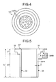
- FIG. 4 is a plan view of the heater/cylinder coupling member when it is viewed from a high temperature side working space side.
- FIG. 5 is a sectional view of the sleeve configuring the high temperature side piston.
- FIG. 6 is an explanatory view illustrating another configuration of the high temperature side cylinder included in the Stirling engine as the piston engine according to the embodiment.
- FIGS. 3 to 6 illustrate the high temperature side piston 20H and the high temperature side cylinder 30H of the Stirling engine 100 illustrated in FIG. 1 . Note that FIGS. 3 and 6 illustrate a state that the high temperature side piston 20H is located at a Top Dead Center (TDC: Upper Dead Point).
- TDC Top Dead Center
- An apex surface 20T of the high temperature side piston 20H is thermally expanded in contact with the high temperature working fluid heated by the heater 105. Since the Stirling engine 100 illustrated in FIG. 1 forms the gas bearing GB between the high temperature side piston 20H and the sleeve 30HR that constitutes the high temperature side cylinder 30H, the clearance tc between the high temperature side piston 20H and the sleeve 30HR is set a small size of several microns to several tens of microns. Accordingly, when the high temperature side piston 20H thermally expands in a diameter direction, there is a possibility that the high temperature side piston 20H is in contact with the sleeve 30HR of the high temperature side cylinder 30H.
- a diameter D1 in a portion of a distance L1 from the apex surface 20T of the high temperature side piston 20H to a predetermined position Kp is made smaller than a diameter D2 in a portion of a distance L2 from the predetermined position Kp to a counter apex surface side end 20B.
- the predetermined position Kp described above is called a piston side stepped portion (a portion illustrated by B of FIG. 3 ).
- the high temperature side piston 20H when the high temperature side piston 20H reaches the TDC, the high temperature side piston 20H enters up to the inside of the heater/cylinder coupling member 120.
- a distance L3 from the apex surface 20T of the high temperature side piston 20H to the piston side stepped portion Kp is made smaller than the distance L1 from the apex surface 20T in the high temperature side piston 20H to the piston side stepped portion Kp illustrated in FIG. 3 . Accordingly, in the high temperature side piston 20H illustrated in FIG. 3 , the piston side stepped portion Kp does not enter up to the inside of the heater/cylinder coupling member 120 in the TDC. In contrast, in the high temperature side piston 20H illustrated in FIG.
- the piston side stepped portion Kp enters up to the inside of the heater/cylinder coupling member 120 in the TDC. Accordingly, in the configuration illustrated in FIG. 6 , there is a possibility that the high temperature side piston 20H is in contact with the heater/cylinder coupling member 120 in the TDC by the thermal expansion of the high temperature side piston 20H in the diameter direction.
- an inside diameter Di1 of the heater/cylinder coupling member 120 may be formed larger than the inside diameter Di of the sleeve 30HR of the high temperature side cylinder 30H as illustrated in FIG. 6 .
- a clearance tch1 from the apex surface 20T of the high temperature side piston 20H to the piston side stepped portion Kp between the high temperature side piston 20H and the heater/cylinder coupling member 120 is made larger than the clearance tc between a side peripheral surface 20S of the high temperature side piston 20H and the inner peripheral surface 33 of the sleeve 30HR of the high temperature side cylinder 30H.
- the clearance tch1 is (Di1 - D1)/2, and the clearance tc is (Di - D2)/2.
- the working fluid which is heated by the heater 105 by, for example, the exhaust gas Ex of the internal combustion engine, is in contact with the apex surface 20T of the high temperature side piston 20H as a heat medium as described above.
- the heat of the working fluid flows from the apex surface 20T of the high temperature side piston 20H to the side peripheral surface 20S connecting to the apex surface with a result that, when the Stirling engine 100 is in operation, a temperature of the high temperature side piston 20H increases in comparison with that a case that the Stirling engine 100 stops. Accordingly, when the Stirling engine 100 is in operation, the high temperature side piston 20H expands in the diameter direction from the apex surface 20T to the counter apex surface side end 20B.
- an outside of the high temperature side cylinder 30H in which the high temperature side piston 20H is accommodated, is in contact with outside air. Accordingly, a temperature of an outside of the high temperature side cylinder 30H is made lower than a temperature of an inside of the high temperature side cylinder 30H into which the working fluid flows (that is, than a temperature of the high temperature side working space MSH illustrated in FIG. 1 ). Accordingly, a temperature of an inner peripheral surface of the high temperature side cylinder 30H, which confronts the side peripheral surface 20S of the high temperature side piston 20H, is made lower than a temperature of the high temperature side piston 20H, and thermal expansion of the high temperature side cylinder 30H in the diameter direction is made smaller than thermal expansion of the high temperature side piston 20H in the diameter direction.
- the embodiment is configured to reduce a difference between the temperature of the high temperature side piston 20H and the temperature of the high temperature side cylinder 30H (hereinafter, called a temperature difference between piston and cylinder).
- a temperature difference between piston and cylinder since the thermal expansion difference between piston and cylinder is reduced, a contact between the high temperature side piston 20H and the high temperature side cylinder 30H can be avoided.
- the sleeve 30HR which constitutes the high temperature side cylinder 30H is thermally connected to the heater 105 for heating the working fluid. More specifically, the sleeve 30HR has a structure formed by extending the heater 105.
- the thermal connection of the sleeve 30HR to the heater 105 means to transfer the heat of the heater 105 to the sleeve 30HR well by connecting the sleeve 30HR to the heater 105 through a heat transfer structure.
- the heat transfer structure has a structure, in which a portion for connecting the sleeve 30HR to the heater 105 is composed of a good heat conductor such as a metal material and the sleeve 30HR is connected to the heater 105, and further a structure in which a good heat conductor (for example, a metal paste such as a silver paste and a copper paste) is interposed between the sleeve 30HR and the heater 105.
- a good heat conductor for example, a metal paste such as a silver paste and a copper paste
- heat transfer structures there are, for example, a structure for connecting the sleeve 30HR to the heater 105 through a material excellent in a heat transfer property interposed therebetween and a structure for connecting the sleeve 30HR to the heater 105 through a heat transfer member composed of a metal material which is a good heat conductor. Further, a structure in which the sleeve 30HR and the heater 105 are composed of the same structural member also corresponds to the heat transfer structure of the embodiment.
- the heat of the heater 105 heated by, for example, the exhaust gas Ex is transmitted to the sleeve 30HR by heat transfer. Since the sleeve 30HR is composed of a material having high thermal conductivity such as metal, the heat of the heater 105 is efficiently transmitted to the sleeve 30HR. With this operation, even if heat is radiated to the outside of the sleeve 30HR, since heat is applied to the sleeve 30HR by the heater 105, a temperature drop of the sleeve 30HR is suppressed. As a result, since the temperature difference between piston and cylinder can be reduced, the thermal expansion difference between piston and cylinder is reduced.
- the cylinder block 30HB is disposed outside of the sleeve 30HR at a predetermined interval.
- the high temperature side cylinder 30H is composed of the double structure in which the cylinder block 30HB is disposed outside of the sleeve 30HR at a predetermined interval.
- a gas layer in the embodiment, an air layer
- a gas layer is formed between an outer peripheral surface 34 of the sleeve 30HR and an inner peripheral surface 35 of the cylinder block 30HB as well as the sleeve 30HR is not in contact with the cylinder block 30HB.
- a gasket 40 is disposed between the cylinder block 30HB and the housing reinforcing member 114B.
- the cylinder block 30HB and the housing reinforcing member 114B are hermetically sealed to thereby secure gas tightness of the crank case 114A.
- the gasket 40 may be provided with a function as an insulation member.
- a counter heater side end 31 of the sleeve 30HR is not in contact with the cylinder block 30HB.
- a temperature of the cylinder block 30HB becomes lower as it is more away from the heater 105, the temperature drop of the sleeve 30HR disposed inside of the cylinder block 30HB through the gas layer is smaller than that of the cylinder block 30HB. Accordingly, a temperature difference between the sleeve 30HR and the cylinder block is maximized in the counter heater side end 31 of the sleeve 30HR.
- a heat transfer between the counter heater side end 31 and the cylinder block 30HB is avoided by placing the counter heater side end 31 and the cylinder block 30HB in the non-contact state. With this configuration, the temperature difference between piston and cylinder is reduced by suppressing the temperature drop of the sleeve 30HR.
- a radiation suppressing member 42 having low thermal conductivity may be disposed between the sleeve 30HR and the cylinder block 30HB disposed at the predetermined interval.
- a heat transfer from the sleeve 30HR to the cylinder block 30HB is suppressed so that the temperature drop of the sleeve 30HR is suppressed.
- the radiation suppressing member 42 can be provided also with a function for keeping a shape of the sleeve 30HR.
- Porous ceramic for example, can be used for the radiation suppressing member 42.
- the radiation suppressing member 42 it is preferable to attach a positioning member 41 to an end (the counter heater side end) 31 of the sleeve 30HR opposite to the heater 105 side to prevent removal of the radiation suppressing member 42.
- the positioning member 41 has also a function for positioning the sleeve 30HR at a predetermined position in the cylinder block 30HB when the sleeve 30HR is formed thin in addition to the function for preventing the removal of the radiation suppressing member 42. Accordingly, when the sleeve 30HR is formed thin, it is preferable to dispose the positioning member 41 even when the radiation suppressing member 42 is not used. With this configuration, even when the sleeve 30HR is formed thin, the sleeve 30HR is liable to be kept at the predetermined position in the cylinder block 30HB.
- the positioning member 41 it is preferable to form the positioning member 41 of a non-metal material such as resin, ceramic, having low thermal conductivity to suppress a heat transfer from the sleeve 30HR to the cylinder block 30HB. Further, it is preferable to dispose the positioning member 42 by dividing it in a peripheral direction of the sleeve 30HR. With this configuration, a heat transfer area from the sleeve 30HR to the cylinder block 30HB is reduced so that the heat transfer from the sleeve 30HR to the cylinder block 30HB can be suppressed.
- a non-metal material such as resin, ceramic
- the cylinder block 30HB is disposed outside of the sleeve 30HR at the predetermined interval as well as the cylinder block 30HB is not in contact with the sleeve 30HR through metal.
- the clearance between the high temperature side piston 20H and the high temperature side cylinder 30H is kept to the set value by reducing the temperature difference between piston and cylinder by suppressing the temperature drop of the sleeve 30HR by effectively suppressing the heat transfer from the sleeve 30HR to the cylinder block 30HB.
- the cylinder block 30HB is a structure member for supporting a force (a cylinder axis force) in a direction parallel with a center axis Zc of the high temperature side cylinder 30H, a bending moment acting on the high temperature side cylinder 30H, and the like. Accordingly, the cylinder block 30HB secures a strength by being formed thick to withstand the cylinder axis force and the bending moment.
- the sleeve 30HR receives a pressure of the working fluid existing therein and does not receive the cylinder axis force and the bending moment. Accordingly, it is sufficient to form the sleeve 30HR in a thickness capable of withstanding only the pressure of the working fluid existing therein.
- the sleeve 30HR can be formed to have a thin wall structure. With this configuration, since a heat capacity of the sleeve 30HR becomes small, a responsiveness to a change of heat transferring from the heater 105 to the sleeve 30HR can be improved. Accordingly, even if a temperature of the working fluid in contact with the high temperature side piston 20H is changed by a temperature change of the heater 105, since a temperature of the sleeve 30HR also promptly changes following the temperature change of the heater 105, the temperature difference between piston and cylinder is promptly reduced. As a result, even if a temperature of the heater 105 changes, the clearance between the high temperature side piston 20H and the high temperature side cylinder 30H is kept to the set value, and the function of the gas bearing GB is securely exhibited.
- a portion (gas bearing portion) GBA where at least the gas bearing GB can be formed in a double structure in which the cylinder block 30HB is disposed outside of the sleeve 30HR at a predetermined interval.
- the gas bearing portion GBA is a portion where the clearance tc (several microns to several tens of microns) is formed between the high temperature side piston 20H and the sleeve 30HR of the high temperature side cylinder 30H in one stroke of the high temperature side piston 20H, the clearance tc being necessary to form the gas bearing GB.
- the clearance tc severe microns to several tens of microns
- a portion between a cylinder side stepped portion Kc disposed to a sleeve support portion 32 for supporting the sleeve 30HR and the counter heater side end 31 of the sleeve 30HR in a direction parallel with a center axis Zp of the high temperature side piston 20H and a center axis Zc of the high temperature side cylinder 30H is the gas bearing portion GBA.
- the cylinder side stepped portion Kc is a portion formed when the heater/cylinder coupling member 120 whose inside diameter is more increased than the sleeve 30HR is connected to the sleeve 30HR.
- the sleeve 30HR is thermally connected to the heater 105 as well as the high temperature side cylinder 30H is configured as the double structure as described above, heat radiation from a side peripheral portion of the high temperature side cylinder 30H where a heat radiation amount to the outside air is maximized is suppressed.
- the clearance between the piston and the cylinder is kept to the set value by reducing the thermal expansion difference between piston and cylinder by reducing the temperature difference between piston and cylinder by effectively suppressing the temperature drop of the sleeve 30HR.
- the function of the gas bearing GB can be stably exhibited while the Stirling engine 100 is in operation.
- the Stirling engine when a Stirling engine includes a plurality of cylinders and a plurality of pistons as in the Stirling engine 100 illustrated in FIG. 1 , the Stirling engine is composed of a double structure in which at least one cylinder thermally connects a sleeve to a heater as well as a cylinder block is disposed outside of the sleeve at a predetermined interval.
- the above structure is employed to the high temperature side cylinder 30H of the Stirling engine 100 illustrated in FIG. 1 as described above, the structure may be employed to the low temperature side cylinder 30L.
- the sleeve support portion 32 is disposed to an end of the sleeve 30HR on the heater 105 side.
- the sleeve 30HR and the sleeve support portion 32 are integrally configured as the same structural member, the sleeve 30HR and the sleeve support portion 32 may be configured as different structural members, and the sleeve 30HR and the sleeve support portion 32 may be integrated when they are assembled to the Stirling engine 100.
- the sleeve 30HR and the sleeve support portion 32 are composed of a good heat conductor, for example, a metal material such as steel and aluminum alloy.
- a size of the sleeve 30HR in an axial direction (a direction of the center axis Zc of the cylinder in FIGS. 3 and 6 ) is Lr2, and a size of the sleeve support portion 32 in the axial direction is Lr1.
- An end (heater side end) 32T of the sleeve support portion 32 on the side thereof opposite to a side where the sleeve 30HR is disposed is in contact with and thermally connected to a counter heater side end 120B of the heater/cylinder coupling member 120 which constitutes the heater 105.
- the sleeve 30HR is thermally connected to the heater 105 through the sleeve support portion 32.
- the sleeve support portion 32 is composed of the good heat conductor, the sleeve 30HR is thermally connected to the heater 105.
- the heater 105 is configured by bundling a plurality of tubes through which the working fluid passes. As illustrated in FIG. 4 , a plurality of openings 105TU of the tubes are formed to the heater/cylinder coupling member 120. The working fluid flows into and flows out from the sleeve 30HR through the openings 105TU.
- the sleeve support portion 32 holds the sleeve 30HR in the cylinder block 30HB at a predetermined interval between the sleeve 30HR and the cylinder block 30HB.
- the sleeve support portion 32 is attached to an end of the cylinder block 30HB on the heater 105 side.
- An end of the cylinder block 30HB on the heater 105 side has an opening as well as a stepped portion KDB is formed to the end. More specifically, a portion of the cylinder block 30HB nearer to the opening has a larger inside diameter.
- a portion of the sleeve support portion 32 attached to the cylinder block 30HB has a stepped portion KDR formed in a shape in conformity with the stepped portion KDB formed to the end of the cylinder block 30HB.
- the stepped portion KDR of the sleeve support portion 32 is engaged with the stepped portion KDB of the cylinder block 30HB.
- An insulation member may be disposed between the sleeve support portion 32 and the cylinder block 30HB.
- a wall thickness tr of the sleeve 30HR in a diameter direction is made smaller than a wall thickness of the sleeve support portion 32 in a diameter direction and a wall thickness of the cylinder block 30HB.
- a temperature of the working fluid changes so that the temperature of the high temperature side piston 20H also changes.
- the temperature of the heater 105 changes, although a heat transfer amount from the heater 105 to the sleeve 30HR also changes, since a temperature of the sleeve 30HR is liable to increase by reducing the wall thickness tr of the sleeve 30HR, the temperature of the sleeve 30HR changes promptly in response to the heat transfer amount.
- FIG. 7 is a schematic view illustrating a configuration example when the Sterling engine according to the embodiment is used to recover exhaust heat of an internal combustion engine.
- an output of the Stirling engine 100 is input to an internal combustion engine transmission 4 through a Stirling engine transmission 5 and taken out after the output is combined with an output of an internal combustion engine 1.
- the internal combustion engine 1 is mounted on a vehicle, for example, a passenger car, a track and the like and acts a power source of the vehicle.
- the internal combustion engine 1 generates an output as a main power source while the vehicle travels.
- the Stirling engine 100 cannot generate a minimum necessary output unless a temperature of the exhaust gas Ex increases to a certain degree of temperature. Accordingly, in the embodiment, when the temperature of the exhaust gas Ex discharged from the internal combustion engine 1 exceeds a predetermined temperature, the Stirling engine 100 recovers heat energy from the exhaust gas Ex of the internal combustion engine 1 and generates an output and drives the vehicle together with the internal combustion engine 1. As described above, the Stirling engine 100 acts as a subsidiary power source of the vehicle.
- the heater 105 included in the Stirling engine 100 is disposed in an exhaust path 2 of the internal combustion engine 1. Note that the regenerator 106 (refer to FIG. 1 ) of the Stirling engine 100 may be disposed in the exhaust path 2. The heater 105 included in the Stirling engine 100 is disposed in the hollow heater case 3 disposed in the exhaust path 2.
- the heat energy of the exhaust gas Ex recovered using the Stirling engine 100 is converted to motion energy by the Stirling engine 100.
- a clutch 6 as a power connection/disconnection means is attached to the crank shaft 110 as the output shaft of the Stirling engine 100, and the output of the Stirling engine 100 is transmitted to the Stirling engine transmission 5 through the clutch 6.
- the output of the internal combustion engine 1 is input to the internal combustion engine transmission 4 through an output shaft 1s of the internal combustion engine 1.
- the internal combustion engine transmission 4 combines the output of the internal combustion engine 1 with the output of the Stirling engine 100 which is output from the Stirling engine transmission 5, outputs the combined output to a transmission output shaft 9, and drives drive wheels 11 through a differential gear 10.
- the clutch 6 as the power connection/disconnection means is disposed between the internal combustion engine transmission 4 and the Stirling engine 100.
- the clutch 6 is disposed between an input shaft 5s of the Stirling engine transmission 5 and the crank shaft 110 of the Stirling engine 100.
- the clutch 6 When the clutch 6 is engaged and disengaged, the clutch 6 mechanically connects and disconnects the crank shaft 110 of the Stirling engine 100 to and from the input shaft 5s of the Stirling engine transmission 5.
- the clutch 6 is controlled by an engine ECU 50.
- the crank shaft 110 of the Stirling engine 100 When the clutch 6 is engaged, the crank shaft 110 of the Stirling engine 100 is directly coupled with the output shaft 1s of the internal combustion engine 1 through the Stirling engine transmission 5 and the internal combustion engine transmission 4. With this operation, the output generated by the Stirling engine 100 is combined with the output generated by the internal combustion engine 1 by the internal combustion engine transmission 4 and taken out from the transmission output shaft 9. In contrast, when the clutch 6 is disengaged, the output shaft 1s of the internal combustion engine 1 is disconnected from the crank shaft 110 of the Stirling engine 100 and rotates.
- the cylinders (at least the high temperature side cylinder) included in the Stirling engine 100 illustrated in FIG. 7 have the structure described above. With this configuration, since the temperatures of the pistons and the cylinders can be kept to the same level, even if the pistons receive heat from the high temperature working fluid and are expanded in the diameter direction, the cylinders are also thermally expanded in the diameter direction likewise the pistons. With this operation, contacts between the pistons and the cylinders can be avoided by suppressing an abrupt reduction of the clearances between the pistons and the cylinders.
- the Stirling engine 100 when the Stirling engine 100 is operated while the vehicle travels, since a possibility that the pistons come into contact with the cylinders can be reduced, the Stirling engine 100 can be stably operated as well as deterioration of durability of the pistons and the cylinders can be suppressed.
- the Stirling engine 100 according to the embodiment when the Stirling engine 100 according to the embodiment is used to recover exhaust heat of the internal combustion engine 1 mounted on the vehicle, the exhaust heat can be stably recovered as well as sufficient durability can be secured.
- the embodiment described above is the piston engine including the gas bearings interposed between the pistons and the cylinders, and the piston engine includes the sleeves into which the working fluid of the piston engine, which has passed through the heater for heating the working fluid, flows, the sleeves are thermally connected to the heater as well as the outer shells are disposed outside of the sleeves, and the cylinders are composed of the double structure of the sleeves and the outer shells.
- the clearances between the sleeves and the pistons can be kept to the set value, a function of the gas bearings can be securely exhibited.
- the pistons are liable to come into contact with the cylinders by a thermal expansion of the pistons.
- the embodiment is preferable because the function of the gas bearings can be securely exhibited by suppressing a possibility that the pistons come into contact with the cylinders.
- the piston engine and the Stirling engine according to the present invention are useful for a piston engine for supporting pistons in cylinders by gas bearings without using piston rings, and in particular suitable to avoid a contact of the pistons with the cylinders.
Landscapes
- Engineering & Computer Science (AREA)
- Chemical & Material Sciences (AREA)
- Combustion & Propulsion (AREA)
- Mechanical Engineering (AREA)
- General Engineering & Computer Science (AREA)
- Magnetic Bearings And Hydrostatic Bearings (AREA)
- Cylinder Crankcases Of Internal Combustion Engines (AREA)
Abstract
Description
- The present invention relates to a piston engine and a Stirling engine in which pistons make reciprocating motions in cylinders without using piston rings and a lubricant.
- Recently, attention has been paid to a Stirling engine which is excellent in theoretical heat efficiency to recover exhaust heat from an internal combustion engine mounted on a vehicle such as a passenger car, a bus, and a truck and exhaust heat from a factory.
Patent Document 1 discloses a Stirling engine in which gas bearings are interposed between pistons and cylinders as well as the pistons are supported by approximately linear mechanisms and reciprocatingly moved. - Patent Document 1: Japanese Patent Application Laid-open No.
2005-106009 FIGS. 1 and5 ) - Incidentally, in a Stirling engine, since apexes surface of pistons are in contact with a working fluid, apexes of the pistons, which are particularly in contact with a high temperature working fluid, thermally expand. When gas bearings are interposed between pistons and cylinders as in the Stirling engine disclosed in
Patent Document 1, minute clearances must be formed between the pistons and the cylinders. Accordingly, when the pistons thermally expand while the Stirling engine is in operation, there is a possibility that the pistons are in contact with the cylinders. An object of the invention, which was made in view of the above problem, is to reduce a possibility of contact between pistons and cylinders when gas bearings are interposed between the pistons and the cylinders. - In order to achieve the above mentioned object, a piston engine according to the present invention includes cylinders including sleeves into which a working fluid flows and thermally connected to a heater, the working fluid being passed through the heater that heats the working fluid; pistons that makes reciprocating motions in the sleeves by a pressure change of the working fluid; and gas bearings formed between inner peripheral surfaces of the sleeves and outer peripheral surfaces of the pistons, the inner peripheral surfaces of the sleeves and the outer peripheral surfaces of the pistons being disposed in confrontation with each other.
- In order to achieve the above mentioned object, a piston engine according to the present invention includes cylinders including sleeves into which a working fluid flows and thermally connected to a heater, and outer shells disposed outside of the sleeves, the working fluid being passed through the heater that heats the working fluid; pistons that makes reciprocating motions in the sleeves by a pressure change of the working fluid; and gas bearings formed between inner peripheral surfaces of the sleeves and outer peripheral surfaces of the pistons, the inner peripheral surfaces of the sleeves and the outer peripheral surfaces of the pistons being disposed in confrontation with each other.
- In order to achieve the above mentioned object, a piston engine according to the present invention includes cylinders composed of a double structure including sleeves into which a working fluid flows and outer shells disposed outside of the sleeves, the working fluid being passed through the heater that heats the working fluid; pistons that makes reciprocating motions in the sleeves by a pressure change of the working fluid; and gas bearings formed between inner peripheral surfaces of the sleeves and outer peripheral surfaces of the pistons, the inner peripheral surfaces of the sleeves and the outer peripheral surfaces of the pistons being disposed in confrontation with each other.
- As a preferred aspect of the present invention, in the piston engine, it is preferred that portions where at least the gas bearings can be formed have a double structure in which the outer shells are disposed outside of the sleeves.
- It is preferred that the sleeves and the outer shells are composed of a different structural member, respectively, and sleeve support portions are disposed to ends of the sleeves on the heater side; and the sleeves are attached to the outer shells by attaching the sleeve support portions to one end of the outer shells, and the sleeves are coupled with the heater.
- As a preferred aspect of the present invention, in the piston engine, it is preferred that the sleeves are not in contact with the outer shells through metal in portions where the gas bearings are formed.
- As a preferred aspect of the present invention, in the piston engine, it is preferred that the sleeves and the outer shells are disposed at predetermined intervals.
- As a preferred aspect of the present invention, in the piston engine, it is preferred that the outer shells support a force which acts on the cylinders and is in a direction parallel to a center axis of the cylinder, and the sleeves receive a pressure of the working fluid existing in the sleeves.
- In order to achieve the above mentioned object, a Stirling engine according to the present invention includes a heat exchanger including a heater that heats a working fluid, a regenerator that is connected to the heater and through which the working fluid passes, and a cooler that is connected to the regenerator and cools the working fluid; cylinders including sleeves into which the working fluid passed through the heater flows and thermally connected to the heater, and outer shells disposed outside of the sleeves; pistons that make reciprocating motions in the sleeves by a pressure change of the working fluid; and gas bearings that are formed between inner peripheral surfaces of the sleeves and outer peripheral surfaces of the pistons, the inner peripheral surfaces of the sleeves and the outer peripheral surfaces of the pistons being disposed in confrontation with each other.
- As a preferred aspect of the present invention, in the Stirling engine, it is preferred that portions where at least the gas bearings can be formed have a double structure in which the outer shells are disposed outside of the sleeves.
- As a preferred aspect of the present invention, in the Stirling engine, it is preferred that the pistons are supported by approximately linear mechanisms.
- As a preferred aspect of the present invention, in the Stirling engine, it is preferred that when the Stirling engine includes a plurality of cylinders and a plurality of pistons, at least one of the cylinders thermally connects between the heater and the sleeves; and
at least the one of the cylinders is composed of a double structure having the sleeve and an outer shell disposed outside of the sleeve. - When gas bearings are interposed between pistons and cylinders, the present invention can reduce a possibility that the pistons are in contact with the cylinders.
-
- [
FIG. 1] FIG. 1 is a sectional view illustrating a configuration of a Stirling engine as a piston engine according to an embodiment. - [
FIG. 2] FIG. 2 is an explanatory view illustrating a configuration example of a gas bearing included in the Stirling engine as the piston engine according to the embodiment and a support structure of the piston. - [
FIG. 3] FIG. 3 is an explanatory view illustrating a configuration of a high temperature side cylinder included in the Stirling engine as the piston engine according to the embodiment. - [
FIG. 4] FIG. 4 is plan view of a heater/cylinder coupling member when it is viewed from a high temperature side working space side. - [
FIG. 5] FIG. 5 is a sectional view of a sleeve configuring a high temperature side piston. - [
FIG. 6] FIG. 6 is an explanatory view illustrating another configuration of the high temperature side cylinder included in the Stirling engine as the piston engine according to the embodiment. - [
FIG. 7] FIG. 7 is a schematic view illustrating a configuration example when the Stirling engine according to the embodiment is used to recover exhaust heat from an internal combustion engine. -
- 20
- Piston
- 20B
- Counter apex surface side end
- 20H
- High temperature side piston
- 20L
- Low temperature side piston
- 20S
- Side peripheral surface
- 20T
- Apex surface
- 30
- Cylinder
- 30H
- High temperature side cylinder
- 30HB, 30LB
- Cylinder block
- 30HR, 30LR
- Sleeve
- 30L
- Low temperature side cylinder
- 31
- Counter heater side end
- 32
- Sleeve support portion
- 40
- Gasket
- 41
- Positioning member
- 42
- Radiation suppressing member
- 60
- Grasshopper mechanism (approximately linear mechanism)
- 100
- Stirling engine
- 100C
- Housing
- 105
- Heater
- 106
- Regenerator
- 107
- Cooler
- 108
- Heat exchanger
- 110
- Crank shaft
- 111
- Base plate
- 120
- Heater/cylinder coupling member
- 120B
- Counter heater side end
- 121
- Cooler/cylinder coupling member
- The present invention will be explained below in detail referring to the drawings. Note that the present invention is by no means limited by the best mode for carrying out the present invention (hereinafter, referred to as an embodiment). Further, components of the following embodiment include components that can be easily conceived by a person skilled in the art, substantially the same components, and components within a so-called equivalent range.
- Note that a Stirling engine that is an external combustion engine will be explained below as an example of a piston engine. Although the piston engine is preferably the external combustion engine in the embodiment as described above, the piston engine is not limited to the external combustion engine. Further, although an example, in which exhaust heat from an internal combustion engine mounted on a vehicle and the like is recovered using the Stirling engine as the piston engine, will be explained, a target from which exhaust heat is recovered is not limited to the internal combustion engine. The present invention can be also applied to a case in which exhaust heat from, for example, a factory, a plant, and a power generation facility is recovered.
- The embodiment is a piston engine having gas bearings interposed between pistons and cylinders and has a feature in that the embodiment includes sleeves into which a working fluid of the piston engine, which has passed through a heater for heating the working fluid, flows and the sleeves are thermally connected to the heater. Further, in the embodiment, outer shells are disposed outside of the sleeves, and the cylinders are configured in a double structure of the sleeves and the outer shells.
-
FIG. 1 is a sectional view illustrating a configuration of the Stirling engine as the piston engine according to the embodiment.FIG. 2 is an explanatory view illustrating a configuration example of the gas bearing included in the Stirling engine as the piston engine according to the embodiment and a support structure of the piston. AStirling engine 100 as the piston engine according to the embodiment is a so-called α type parallel two-cylinder Stirling engine. The parallel two-cylinder is configured such that two cylinders are arranged in a direction parallel with a rotating shaft of acrank shaft 110 as an output shaft of theStirling engine 100. In the embodiment, theStirling engine 100 disposes aheat exchanger 108 to aheater case 3 acting as a path through which an exhaust gas Ex from an internal combustion engine is caused to pass and is used as an exhaust heat recover device for recovering heat energy from the exhaust gas Ex of the internal combustion engine. - The
Stirling engine 100 includes a hightemperature side piston 20H accommodated in a hightemperature side cylinder 30H and a lowtemperature side piston 20L accommodated in a lowtemperature side cylinder 30L, and the hightemperature side piston 20H is disposed in series with the lowtemperature side piston 20L. Theheat exchanger 108 is disposed between the hightemperature side cylinder 30H and the lowtemperature side cylinder 30L. Note that, in the following description, when the hightemperature side cylinder 30H and the lowtemperature side cylinder 30L are not discriminated from each other, they are called acylinder 30, and when the hightemperature side piston 20H and the lowtemperature side piston 20L are not discriminated from each other, they are called apiston 20. - The high
temperature side cylinder 30H and the lowtemperature side cylinder 30L are directly or indirectly supported by and fixed to abase plate 111 as a reference member. In theStirling engine 100 according to the embodiment, thebase plate 111 acts as a position reference of respective components of theStirling engine 100. With this configuration, the relative positional accuracies of the respective components can be secured. Further, as described later, theStirling engine 100 according to the embodiment has gas bearings GB between the hightemperature side cylinder 30H and the hightemperature side piston 20H and between the lowtemperature side cylinder 30L and the lowtemperature side piston 20L. - The high
temperature side cylinder 30H is composed of the double structure including a sleeve 30HR as a cylindrical structural member and a cylinder block 30HB as the outer shell disposed outside of an outer peripheral portion of the sleeve 30HR. The sleeve 30HR has the hightemperature side piston 20H disposed therein with a result that an inner peripheral surface of the sleeve 30HR and an outer peripheral surface of the hightemperature side piston 20H are disposed in confrontation with each other. The gas bearing GB is formed between the sleeve 30HR and the hightemperature side piston 20H, and the hightemperature side piston 20H makes a reciprocating motion in the sleeve 30HR while being supported in the sleeve 30HR through the gas bearing GB. - A working space (high temperature side working space) MSH, in which the working fluid of the
Stirling engine 100 exists, is formed in the sleeve 30HR. The high temperature side working space MSH is a space surrounded by an inner surface of the sleeve 30HR, an apex surface of the hightemperature side piston 20H, and an end of aheater 105 connected to the hightemperature side cylinder 30H.
In the embodiment, the working fluid of theStirling engine 100 is air. The working fluid, which has passed through theheater 105 for heating the working fluid, flows into the sleeve 30HR, that is, into the high temperature side working space MSH. Further, the working fluid flows into theheater 105 from the high temperature side working space MSH. The hightemperature side piston 20H makes the reciprocating motion in the sleeve 30HR by a pressure change of the working fluid in the high temperature side working space MSH. - The low
temperature side cylinder 30L is composed of a sleeve 30LR as a cylindrical structural member and a cylinder block 30LB as the outer shell disposed outside of the outer peripheral portion of the sleeve 30LR. Note that the sleeve 30LR and the cylinder block 30LB may be composed of the same structural member without disposing the sleeve 30LR. The lowtemperature side piston 20L is disposed in the sleeve 30LR so that an inner peripheral surface of the sleeve 30LR is disposed in confrontation with an outer peripheral surface of the lowtemperature side piston 20L. The gas bearing GB is formed between the sleeve 30LR and the lowtemperature side piston 20L, and the lowtemperature side piston 20L is supported in the sleeve 30LR by the gas bearing GB and makes a reciprocating motion in the sleeve 30LR. - A working space (low temperature side working space) MSL, in which the working fluid of the
Stirling engine 100 exists, is formed in the sleeve 30LR. The low temperature side working space MSL is a space surrounded by an inner surface of the sleeve 30LR, an apex surface of the lowtemperature side piston 20L, and an end of a cooler 107 connected to the lowtemperature side cylinder 30L. The working fluid, which has passed through the cooler 107 for cooling the working fluid, flows into the sleeve 30LR, that is, into the low temperature side working space MSL. Further, the working fluid flows into the cooler 107 from the low temperature side working space MSL. The lowtemperature side piston 20L makes a reciprocating motion in the sleeve 30LR by a pressure change of the working fluid in the low temperature side working space MSL. - The
Stirling engine 100 indirectly attaches the hightemperature side cylinder 30H and the lowtemperature side cylinder 30L to thebase plate 111 as the reference member. With this configuration, a clearance between thepiston 20 and thecylinder 30 can be accurately kept by securing a position accuracy between thepiston 20 and thecylinder 30 using thebase plate 111. With this configuration, a function of the gas bearing GB can be sufficiently exhibited. Further, theStirling engine 100 can be also easily assembled. Note that the hightemperature side cylinder 30H and the lowtemperature side cylinder 30L may be directly attached to thebase plate 111. - The
heat exchanger 108, which is composed of an approximately U-shaped heater (heating device) 105, aregenerator 106, and the cooler 107, is disposed between the hightemperature side cylinder 30H and the lowtemperature side cylinder 30L. Theheater 105 can be easily disposed also to a relatively narrow space such as an exhaust gas path of an internal combustion engine by forming theheater 105 in the approximately U-shape as described above. Further, when the hightemperature side cylinder 30H and the lowtemperature side cylinder 30L are disposed in series as in theStirling engine 100, theheater 105 can be relatively easily disposed in a cylindrical space such as an exhaust gas path of the internal combustion engine. - One end of the
heater 105 is disposed on the hightemperature side cylinder 30H side, and the other end of theheater 105 is disposed on theregenerator 106 side. One end of theregenerator 106 is disposed on theheater 105 side and the other end of theregenerator 106 is disposed on the cooler 107 side, and the working fluid, which flows in from theheater 105 or the cooler 107, passes through theregenerator 106. One end of the cooler 107 is disposed on theregenerator 106 side, and the other end of the cooler 107 is disposed on the lowtemperature side cylinder 30L side. - A heater/
cylinder coupling member 120 is attached to an end of theheater 105 disposed on the hightemperature side cylinder 30H side. The heater/cylinder coupling member 120 is composed of a good heat conductor such as metal and constitutes a part of theheater 105. An end of the heater/cylinder coupling member 120 opposite to a side thereof connected to theheater 105 is attached to the hightemperature side cylinder 30H, and, more specifically, to the sleeve 30HR that constitutes the hightemperature side cylinder 30H. With this configuration, theheater 105 is connected to the hightemperature side cylinder 30H through the heater/cylinder coupling member 120. While theStirling engine 100 is in operation, the working fluid, which has passed through theheater 105, flows into the hightemperature side cylinder 30H as well as the working fluid in the hightemperature side cylinder 30H flows into theheater 105. - A cooler/
cylinder coupling member 121 is attached to an end of the cooler 107 disposed on the lowtemperature side cylinder 30L side. An end of the cooler/cylinder coupling member 121 opposite to a side thereof connected to the cooler 107 is attached to the lowtemperature side cylinder 30L. With this configuration, the cooler 107 is connected to the lowtemperature side cylinder 30L through the cooler/cylinder coupling member 121. While theStirling engine 100 is in operation, the working fluid, which has passed through the cooler 107, flows into the lowtemperature side cylinder 30L as well as the working fluid in the lowtemperature side cylinder 30L flows into the cooler 107. - The heater/
cylinder coupling member 120 is attached to thebase plate 111 through aflange 120F expanding to an outer peripheral portion of the heater/cylinder coupling member 120. With this configuration, the hightemperature side cylinder 30H is attached to thebase plate 111 through the heater/cylinder coupling member 120. The cooler/cylinder coupling member 121 is attached to thebase plate 111 through aflange 121F expanding to an outer peripheral portion of the cooler/cylinder coupling member 121. With this configuration, the lowtemperature side cylinder 30L is attached to thebase plate 111 through the cooler/cylinder coupling member 121. - The
heater 105 heats the working fluid of theStirling engine 100. The cooler 107 cools the working fluid. The working fluid, which has passed through theheat exchanger 108, flows into and flows out from the hightemperature side cylinder 30H and the lowtemperature side cylinder 30L. The working fluid is contained in the sleeve 30HR of the hightemperature side cylinder 30H, in the sleeve 30LR of the lowtemperature side cylinder 30L, and in theheat exchanger 108, and a Stirling cycle is formed by the heat supplied from theheater 105 to thereby drive theStirling engine 100. - For example, the
heater 105 and the cooler 107 can be formed by bundling a plurality of tubes of a material having a high thermal conductivity and an excellent heat resistance. The cooler 107 may be cooled by air or by water. Further, theregenerator 106 is composed of, for example, a porous heat accumulating member. Note that the configurations of theheater 105, the cooler 107, and theregenerator 106 are not limited to those exemplified above, and preferable configurations can be selected according to a heat condition of an exhaust heat recovery target, a specification of theStirling engine 100, and the like. - As described above, the high
temperature side piston 20H and the lowtemperature side piston 20L are supported in the hightemperature side cylinder 30H and the lowtemperature side cylinder 30L through the gas bearings GB. That is, this is a structure for supporting the hightemperature side piston 20H and the lowtemperature side piston 20L in thecylinders Stirling engine 100 can be improved by reducing friction between thepiston 20 and thecylinder 30. Further, even when theStirling engine 100 is used under the operating condition of, for example, a low heat source and a low temperature difference as in a case of recovering exhaust heat from an internal combustion engine, heat energy can be recovered from the exhaust heat by theStirling engine 100 by reducing friction between thepiston 20 and thecylinder 30. - To constitute the gas bearings GB, predetermined clearances tc are formed between the high
temperature side piston 20H and the lowtemperature side piston 20L and the sleeves 30HR, 30LR as illustrated inFIG. 2 . The clearance tc is formed in several microns to several tens of microns around an entire periphery of thepiston 20. The reciprocating motions of the hightemperature side piston 20H and the lowtemperature side piston 20L are transmitted to the crankshaft 110 as an output shaft by a connectingrod 61 and converted to a rotational motion by thecrank shaft 110. - Since the gas bearing GB has a low capability (load capability) for withstanding force in a diameter direction (lateral direction, thrust direction) of the
piston 20, it is preferable to set side force Fs of thepiston 20 to substantially 0. Accordingly, a high linear motion accuracy of thepiston 20 to the axial line (center axis) of thecylinder 30 is required. To realize the high linear motion accuracy, in the embodiment, the hightemperature side piston 20H and the lowtemperature side piston 20L are supported by approximately linear mechanisms (for example, grasshopper mechanisms) 60 illustrated inFIG. 2 . The hightemperature side piston 20H and the lowtemperature side piston 20L make approximately linear reciprocating motions by the approximatelylinear mechanisms 60 as well as the reciprocating motions are transmitted to the crankshaft 110 through the connectingrod 61. With this operation, the reciprocating motions of the hightemperature side piston 20H and the lowtemperature side piston 20L supported by the approximatelylinear mechanisms 60 are converted to a rotating motion by thecrank shaft 110, and the rotating motion is taken out as an output of theStirling engine 100. More specifically, theStirling engine 100 obtains the output by converting the reciprocating motions of the hightemperature side piston 20H and the lowtemperature side piston 20L supported by the approximatelylinear mechanisms 60 to the rotating motion by thecrank shaft 110. - In the embodiment, for example, almost all the side force Fs is supported by the approximately
linear mechanisms 60, and the side force Fs, which is generated when the reciprocating motion of thepiston 20 is away from an approximately linear motion, is supported by the gas bearing GB. In the embodiment, the grasshopper mechanisms are used for the approximatelylinear mechanisms 60. The approximatelylinear mechanisms 60 are calledgrasshopper mechanisms 60 in the following description. - Each of the
grasshopper mechanisms 60 is composed of afirst arm 62 having one end rotatably attached to ahousing 100C of theStirling engine 100, asecond arm 63 having one end rotatably attached to thehousing 100C of theStirling engine 100 likewise, and athird arm 64 having one end rotatably coupled with an end of the connectingrod 61 and the other end rotatably coupled with the other end of thesecond arm 63. An end of the connectingrod 61, which is different from the end thereof rotatably attached to the crankshaft 110, is rotatably coupled with an end of thethird arm 64. Further, the other end of thefirst arm 62 is rotatably coupled between both the ends of thethird arm 63. - The high
temperature side piston 20H and the lowtemperature side piston 20L can be approximately linearly reciprocated by use of thegrasshopper mechanisms 60. As a result, since the side force Fs of thepiston 20 becomes almost 0, thepiston 20 can be sufficiently supported even by the gas bearing GB having a small load capability. Note that the approximately linear mechanism for supporting thepiston 20 is not limited to the grasshopper mechanism, and a watts link and the like may be used. - Since the
grasshopper mechanisms 60 can obtain the same linear motion accuracy by a size smaller than that of other linear approximation mechanisms, thegrasshopper mechanisms 60 are advantageous in that theStirling engine 100 can be made compact in its entirety. In particular, when a Stirling engine is installed in a limited space as in a case in which theStirling engine 100 is used to recover exhaust heat from an internal combustion engine mounted on a vehicle and theheat exchanger 108 is disposed in an exhaust gas path of the internal combustion engine, a degree of freedom of installation can be improved when theStirling engine 100 is compact in its entirety. Since the weight of thegrasshopper mechanism 60 for obtaining the same linear motion accuracy is smaller than that of the other mechanisms, thegrasshopper mechanism 60 is advantageous to improve heat efficiency. Further, since thegrasshopper mechanism 60 is relatively simply configured, thegrasshopper mechanism 60 is advantageous in that it can be easily manufactured and assembled and can reduce also a manufacturing cost. - As illustrated in
FIG. 1 , components such as the hightemperature side piston 20H, the connectingrod 61, and thecrank shaft 110 which constitute theStirling engine 100 are accommodated in thehousing 100C. Thehousing 100C includes a crankcase 114A, the cylinder blocks 30HB, 30LB, and ahousing reinforcing member 114B. - In the embodiment, the crank
case 114A, which constitutes thehousing 100C of theStirling engine 100, is filled with a gas. In the embodiment, the gas is the same as the working fluid of theStirling engine 100. The gas filled in thecrank case 114A is pressurized by apump 115 as a pressure adjustment unit. Thepump 115 may be driven by, for example, an internal combustion engine as an exhaust heat recovery target of theStirling engine 100 or may be driven by, for example, a drive means such as a motor. - When a temperature difference is the same between the
heater 105 and the cooler 107, since a higher average pressure of the working fluid more increases a pressure difference between a high temperature side and a low temperature side, theStirling engine 100 can obtain a higher output. TheStirling engine 100 is configured such that the working fluids in the high temperature side working space MSH and the low temperature side working space MSL are kept at a high pressure by pressurizing the gas filled in thecrank case 114A by theStirling engine 100 so that a larger output can be taken out from theStirling engine 100. As a result, even when only a low quality heat source can be used as in an exhaust heat recovery, a larger output can be taken out from theStirling engine 100. The output of theStirling engine 100 is increased approximately in proportion to a pressure of the gas filled in thecrank case 114A. - In the
Stirling engine 100, a seal bearing 116 is attached to the crankcase 114A, and thecrank shaft 110 is supported by theseal bearing 116. Although theStirling engine 100 pressurizes the gas filled in thecrank case 114A, a leakage of the gas filled in thehousing 100C can be minimized by theseal bearing 116. The output from thecrank shaft 110 is taken out to the outside of thecrank case 114A through aflexible coupling 119 such as, for example, an Oldham's coupling. Note that a magnetic coupling, which is coupled with thecrank shaft 110, may be disposed between an inside and an outside of thecrank case 114A, and the output of thecrank shaft 110 may be taken out to the outside of thecrank case 114A through the magnetic coupling. - As illustrated in
FIGS. 1 and2 , in the embodiment, the gas bearings GB are formed by blowing a gas (in the embodiment, air which is the same as the working fluid) A from gas supply openings HE formed around side peripheral portions of the hightemperature side piston 20H and the lowtemperature side piston 20L. As illustrated inFIGS. 1 and2 , a high temperature side piston internal space 20HI and a low temperature side piston internal space 20LI are formed in the hightemperature side piston 20H and the lowtemperature side piston 20L, respectively. - A gas introduction port HI is disposed to the high
temperature side piston 20H to supply the gas A into the high temperature side piston internal space 20HI, and a gas introduction port HI is disposed to the lowtemperature side piston 20L to supply the gas A into the low temperature side piston internal space 20LI. Agas supply pipe 118 is connected to each of the gas introduction ports HI. One end of thegas supply pipe 118 is connected to agas bearing pump 117 and introduces the gas A ejected from thegas bearing pump 117 into the high temperature side piston internal space 20HI and the low temperature side piston internal space 20LI. - The gas A, which is introduced into the high temperature side piston internal space 20HI and the low temperature side piston internal space 20LI, flows out from the gas supply openings HE formed around the side peripheral portions of the high
temperature side piston 20H and the lowtemperature side piston 20L and forms the gas bearings GB. Note that although the gas bearings GB are static pressure gas bearings, a structure of the gas bearings GB is not limited to the static pressure gas bearings and may be dynamic pressure gas bearings in the embodiment. - Further, the gas bearings GB may be formed by forming gas taking-in ports to apex surfaces of the high
temperature side piston 20H and the lowtemperature side piston 20L and taking in the gas A as the working fluid from the gas taking-in ports into the high temperature side piston internal space 20HI and the low temperature side piston internal space 20LI and flows out the gas A from the gas supply openings HE. Note that although the gas bearings GB of the embodiment are the static pressure gas bearings, the dynamic pressure gas bearings may be used. -
FIG. 3 is an explanatory view illustrating a configuration of the high temperature side cylinder included in the Stirling engine as the piston engine according to the embodiment.FIG. 4 is a plan view of the heater/cylinder coupling member when it is viewed from a high temperature side working space side.FIG. 5 is a sectional view of the sleeve configuring the high temperature side piston.FIG. 6 is an explanatory view illustrating another configuration of the high temperature side cylinder included in the Stirling engine as the piston engine according to the embodiment.FIGS. 3 to 6 illustrate the hightemperature side piston 20H and the hightemperature side cylinder 30H of theStirling engine 100 illustrated inFIG. 1 . Note thatFIGS. 3 and6 illustrate a state that the hightemperature side piston 20H is located at a Top Dead Center (TDC: Upper Dead Point). - An
apex surface 20T of the hightemperature side piston 20H is thermally expanded in contact with the high temperature working fluid heated by theheater 105. Since theStirling engine 100 illustrated inFIG. 1 forms the gas bearing GB between the hightemperature side piston 20H and the sleeve 30HR that constitutes the hightemperature side cylinder 30H, the clearance tc between the hightemperature side piston 20H and the sleeve 30HR is set a small size of several microns to several tens of microns. Accordingly, when the hightemperature side piston 20H thermally expands in a diameter direction, there is a possibility that the hightemperature side piston 20H is in contact with the sleeve 30HR of the hightemperature side cylinder 30H. - In the embodiment, a diameter D1 in a portion of a distance L1 from the
apex surface 20T of the hightemperature side piston 20H to a predetermined position Kp is made smaller than a diameter D2 in a portion of a distance L2 from the predetermined position Kp to a counter apexsurface side end 20B. With this configuration, a clearances tch (a portion illustrated by A ofFIG. 3 ) from theapex surface 20T of the hightemperature side piston 20H to the predetermined position Kp between the hightemperature side piston 20H and the sleeve 30HR of the hightemperature side cylinder 30H is made larger than the clearance tc from the predetermined position Kp of the hightemperature side piston 20H to the counter apexsurface side end 20B between the hightemperature side piston 20H and an innerperipheral surface 33 of the sleeve 30HR of the hightemperature side cylinder 30H. Since an inside diameter of the sleeve 30HR of the hightemperature side cylinder 30H is Di, the clearance tch is (Di - D1)/2, and the clearance tc is (Di - D2)/2. With this configuration, even if a vicinity of theapex surface 20T of the hightemperature side piston 20H thermally expands in the diameter direction, a contact between the hightemperature side piston 20H and the sleeve 30HR of the hightemperature side cylinder 30H can be avoided. The predetermined position Kp described above is called a piston side stepped portion (a portion illustrated by B ofFIG. 3 ). - In the embodiment, when the high
temperature side piston 20H reaches the TDC, the hightemperature side piston 20H enters up to the inside of the heater/cylinder coupling member 120. In a configuration illustrated inFIG. 6 , a distance L3 from theapex surface 20T of the hightemperature side piston 20H to the piston side stepped portion Kp is made smaller than the distance L1 from theapex surface 20T in the hightemperature side piston 20H to the piston side stepped portion Kp illustrated inFIG. 3 . Accordingly, in the hightemperature side piston 20H illustrated inFIG. 3 , the piston side stepped portion Kp does not enter up to the inside of the heater/cylinder coupling member 120 in the TDC. In contrast, in the hightemperature side piston 20H illustrated inFIG. 6 , the piston side stepped portion Kp enters up to the inside of the heater/cylinder coupling member 120 in the TDC. Accordingly, in the configuration illustrated inFIG. 6 , there is a possibility that the hightemperature side piston 20H is in contact with the heater/cylinder coupling member 120 in the TDC by the thermal expansion of the hightemperature side piston 20H in the diameter direction. - To avoid the contact, in the configuration in which the piston side stepped portion Kp enters up to the inside of the heater/
cylinder coupling member 120 in the TDC, an inside diameter Di1 of the heater/cylinder coupling member 120 may be formed larger than the inside diameter Di of the sleeve 30HR of the hightemperature side cylinder 30H as illustrated inFIG. 6 . With this configuration, a clearance tch1 from theapex surface 20T of the hightemperature side piston 20H to the piston side stepped portion Kp between the hightemperature side piston 20H and the heater/cylinder coupling member 120 is made larger than the clearance tc between a sideperipheral surface 20S of the hightemperature side piston 20H and the innerperipheral surface 33 of the sleeve 30HR of the hightemperature side cylinder 30H. The clearance tch1 is (Di1 - D1)/2, and the clearance tc is (Di - D2)/2. With this configuration, even if the vicinity of theapex surface 20T of the hightemperature side piston 20H thermally expands in the diameter direction, the contact between the hightemperature side piston 20H and the heater/cylinder coupling member 120 can be avoided. - While the
Stirling engine 100 illustrated inFIG. 1 is in operation, the working fluid, which is heated by theheater 105 by, for example, the exhaust gas Ex of the internal combustion engine, is in contact with theapex surface 20T of the hightemperature side piston 20H as a heat medium as described above. The heat of the working fluid flows from theapex surface 20T of the hightemperature side piston 20H to the sideperipheral surface 20S connecting to the apex surface with a result that, when theStirling engine 100 is in operation, a temperature of the hightemperature side piston 20H increases in comparison with that a case that theStirling engine 100 stops. Accordingly, when theStirling engine 100 is in operation, the hightemperature side piston 20H expands in the diameter direction from theapex surface 20T to the counter apexsurface side end 20B. - In contrast, an outside of the high
temperature side cylinder 30H, in which the hightemperature side piston 20H is accommodated, is in contact with outside air. Accordingly, a temperature of an outside of the hightemperature side cylinder 30H is made lower than a temperature of an inside of the hightemperature side cylinder 30H into which the working fluid flows (that is, than a temperature of the high temperature side working space MSH illustrated inFIG. 1 ). Accordingly, a temperature of an inner peripheral surface of the hightemperature side cylinder 30H, which confronts the sideperipheral surface 20S of the hightemperature side piston 20H, is made lower than a temperature of the hightemperature side piston 20H, and thermal expansion of the hightemperature side cylinder 30H in the diameter direction is made smaller than thermal expansion of the hightemperature side piston 20H in the diameter direction. As described above, since a difference between the thermal expansion of the hightemperature side piston 20H and the thermal expansion of the hightemperature side cylinder 30H (hereinafter, called a thermal expansion difference between piston and cylinder) is generated, the clearance between the hightemperature side piston 20H and the hightemperature side cylinder 30H which was set at first, is reduced and thus there is a possibility that the hightemperature side piston 20H is in contact with the hightemperature side cylinder 30H. - The embodiment is configured to reduce a difference between the temperature of the high
temperature side piston 20H and the temperature of the hightemperature side cylinder 30H (hereinafter, called a temperature difference between piston and cylinder). With this configuration, since the thermal expansion difference between piston and cylinder is reduced, a contact between the hightemperature side piston 20H and the hightemperature side cylinder 30H can be avoided. Next, a configuration for reducing the temperature difference between piston and cylinder will be explained in detail. - In the embodiment, the sleeve 30HR which constitutes the high
temperature side cylinder 30H is thermally connected to theheater 105 for heating the working fluid. More specifically, the sleeve 30HR has a structure formed by extending theheater 105. Here, the thermal connection of the sleeve 30HR to theheater 105 means to transfer the heat of theheater 105 to the sleeve 30HR well by connecting the sleeve 30HR to theheater 105 through a heat transfer structure. - The heat transfer structure has a structure, in which a portion for connecting the sleeve 30HR to the
heater 105 is composed of a good heat conductor such as a metal material and the sleeve 30HR is connected to theheater 105, and further a structure in which a good heat conductor (for example, a metal paste such as a silver paste and a copper paste) is interposed between the sleeve 30HR and theheater 105. Further, as other heat transfer structures, there are, for example, a structure for connecting the sleeve 30HR to theheater 105 through a material excellent in a heat transfer property interposed therebetween and a structure for connecting the sleeve 30HR to theheater 105 through a heat transfer member composed of a metal material which is a good heat conductor. Further, a structure in which the sleeve 30HR and theheater 105 are composed of the same structural member also corresponds to the heat transfer structure of the embodiment. - With these configurations, the heat of the
heater 105 heated by, for example, the exhaust gas Ex is transmitted to the sleeve 30HR by heat transfer. Since the sleeve 30HR is composed of a material having high thermal conductivity such as metal, the heat of theheater 105 is efficiently transmitted to the sleeve 30HR. With this operation, even if heat is radiated to the outside of the sleeve 30HR, since heat is applied to the sleeve 30HR by theheater 105, a temperature drop of the sleeve 30HR is suppressed. As a result, since the temperature difference between piston and cylinder can be reduced, the thermal expansion difference between piston and cylinder is reduced. Since the clearance between the hightemperature side piston 20H and the hightemperature side cylinder 30H is kept to the set value, a contact between the hightemperature side cylinder 30H and the hightemperature side piston 20H can be avoided. With this configuration, a function of the gas bearing GB can be stably exhibited. - In the embodiment, the cylinder block 30HB is disposed outside of the sleeve 30HR at a predetermined interval. As described above, the high
temperature side cylinder 30H is composed of the double structure in which the cylinder block 30HB is disposed outside of the sleeve 30HR at a predetermined interval. When the predetermined interval is formed between the sleeve 30HR and the cylinder block 30HB, a gas layer (in the embodiment, an air layer) is formed between an outerperipheral surface 34 of the sleeve 30HR and an innerperipheral surface 35 of the cylinder block 30HB as well as the sleeve 30HR is not in contact with the cylinder block 30HB. - Since a heat radiation amount from the sleeve 30HR to the cylinder block 30HB can be greatly suppress by the gas layer, the temperature drop of the sleeve 30HR is suppressed. As a result, since the temperature difference between piston and cylinder can be reduced, the thermal expansion difference between piston and cylinder is reduced. Since the clearance between the high
temperature side piston 20H and the hightemperature side cylinder 30H is kept to the set value, the contact between the hightemperature side piston 20H and the hightemperature side cylinder 30H can be avoided. As a result, the function of the gas bearing GB can be stably exhibited. - In the embodiment, a
gasket 40 is disposed between the cylinder block 30HB and thehousing reinforcing member 114B. With this configuration, the cylinder block 30HB and thehousing reinforcing member 114B are hermetically sealed to thereby secure gas tightness of thecrank case 114A. Further, thegasket 40 may be provided with a function as an insulation member. With this configuration, since a heat transfer from the cylinder block 30HB to thehousing reinforcing member 114B and the crankcase 114A is suppressed, a temperature drop of the cylinder block 30HB is suppressed on thehousing reinforcing member 114B side. As a result, an advantage can be obtained in that heat radiation from the sleeve 30HR to the cylinder block 30HB can be suppressed on the crankcase 114A side of the sleeve 30HR. - With the configuration described above, a counter heater side end 31 of the sleeve 30HR is not in contact with the cylinder block 30HB. Although a temperature of the cylinder block 30HB becomes lower as it is more away from the
heater 105, the temperature drop of the sleeve 30HR disposed inside of the cylinder block 30HB through the gas layer is smaller than that of the cylinder block 30HB. Accordingly, a temperature difference between the sleeve 30HR and the cylinder block is maximized in the counter heater side end 31 of the sleeve 30HR. Accordingly, in the embodiment, a heat transfer between the counterheater side end 31 and the cylinder block 30HB is avoided by placing the counterheater side end 31 and the cylinder block 30HB in the non-contact state. With this configuration, the temperature difference between piston and cylinder is reduced by suppressing the temperature drop of the sleeve 30HR. - As illustrated in
FIG. 6 , aradiation suppressing member 42 having low thermal conductivity may be disposed between the sleeve 30HR and the cylinder block 30HB disposed at the predetermined interval. With this configuration, a heat transfer from the sleeve 30HR to the cylinder block 30HB is suppressed so that the temperature drop of the sleeve 30HR is suppressed. As a result, since the temperature difference between piston and cylinder can be reduced, the thermal expansion difference between piston and cylinder is reduced, and thus the clearance between the hightemperature side piston 20H and the hightemperature side cylinder 30H is kept to the set value. Further, when a thin metal is used for the sleeve 30HR, theradiation suppressing member 42 can be provided also with a function for keeping a shape of the sleeve 30HR. - Porous ceramic, for example, can be used for the
radiation suppressing member 42. When theradiation suppressing member 42 is disposed, it is preferable to attach apositioning member 41 to an end (the counter heater side end) 31 of the sleeve 30HR opposite to theheater 105 side to prevent removal of theradiation suppressing member 42. The positioningmember 41 has also a function for positioning the sleeve 30HR at a predetermined position in the cylinder block 30HB when the sleeve 30HR is formed thin in addition to the function for preventing the removal of theradiation suppressing member 42. Accordingly, when the sleeve 30HR is formed thin, it is preferable to dispose the positioningmember 41 even when theradiation suppressing member 42 is not used. With this configuration, even when the sleeve 30HR is formed thin, the sleeve 30HR is liable to be kept at the predetermined position in the cylinder block 30HB. - Note that it is preferable to form the positioning
member 41 of a non-metal material such as resin, ceramic, having low thermal conductivity to suppress a heat transfer from the sleeve 30HR to the cylinder block 30HB. Further, it is preferable to dispose the positioningmember 42 by dividing it in a peripheral direction of the sleeve 30HR. With this configuration, a heat transfer area from the sleeve 30HR to the cylinder block 30HB is reduced so that the heat transfer from the sleeve 30HR to the cylinder block 30HB can be suppressed. - As described above, in the embodiment, the cylinder block 30HB is disposed outside of the sleeve 30HR at the predetermined interval as well as the cylinder block 30HB is not in contact with the sleeve 30HR through metal. With this configuration, the clearance between the high
temperature side piston 20H and the hightemperature side cylinder 30H is kept to the set value by reducing the temperature difference between piston and cylinder by suppressing the temperature drop of the sleeve 30HR by effectively suppressing the heat transfer from the sleeve 30HR to the cylinder block 30HB. - In the embodiment, the cylinder block 30HB is a structure member for supporting a force (a cylinder axis force) in a direction parallel with a center axis Zc of the high
temperature side cylinder 30H, a bending moment acting on the hightemperature side cylinder 30H, and the like. Accordingly, the cylinder block 30HB secures a strength by being formed thick to withstand the cylinder axis force and the bending moment. In contrast, the sleeve 30HR receives a pressure of the working fluid existing therein and does not receive the cylinder axis force and the bending moment. Accordingly, it is sufficient to form the sleeve 30HR in a thickness capable of withstanding only the pressure of the working fluid existing therein. - In general, since a cylindrical shape is strong to an internal pressure, even if the cylindrical shape is formed thin, it withstands a considerable internal pressure. Accordingly, the sleeve 30HR can be formed to have a thin wall structure. With this configuration, since a heat capacity of the sleeve 30HR becomes small, a responsiveness to a change of heat transferring from the
heater 105 to the sleeve 30HR can be improved. Accordingly, even if a temperature of the working fluid in contact with the hightemperature side piston 20H is changed by a temperature change of theheater 105, since a temperature of the sleeve 30HR also promptly changes following the temperature change of theheater 105, the temperature difference between piston and cylinder is promptly reduced. As a result, even if a temperature of theheater 105 changes, the clearance between the hightemperature side piston 20H and the hightemperature side cylinder 30H is kept to the set value, and the function of the gas bearing GB is securely exhibited. - In the high
temperature side cylinder 30H, it is preferable to configure a portion (gas bearing portion) GBA where at least the gas bearing GB can be formed in a double structure in which the cylinder block 30HB is disposed outside of the sleeve 30HR at a predetermined interval. With this configuration, in the gas bearing portion GBA, since the thermal expansion difference between piston and cylinder is reduced by reduction of the temperature difference between piston and cylinder, the clearance between the hightemperature side piston 20H and the hightemperature side cylinder 30H is kept to a more securely set value, and the function of the gas bearing GB is exhibited. - The gas bearing portion GBA is a portion where the clearance tc (several microns to several tens of microns) is formed between the high
temperature side piston 20H and the sleeve 30HR of the hightemperature side cylinder 30H in one stroke of the hightemperature side piston 20H, the clearance tc being necessary to form the gas bearing GB. In a configuration illustrated inFIG. 3 , when the hightemperature side piston 20H is located in the TDC in a direction parallel with a center axis (an axis parallel with a center axis of the hightemperature side piston 20H) Zc of the hightemperature side cylinder 30H, a portion between the piston side stepped portion Kp and the counter heater side end 31 of the sleeve 30HR is the gas bearing portion GBA. - Further, in an example illustrated in
FIG. 6 , a portion between a cylinder side stepped portion Kc disposed to asleeve support portion 32 for supporting the sleeve 30HR and the counter heater side end 31 of the sleeve 30HR in a direction parallel with a center axis Zp of the hightemperature side piston 20H and a center axis Zc of the hightemperature side cylinder 30H is the gas bearing portion GBA. The cylinder side stepped portion Kc is a portion formed when the heater/cylinder coupling member 120 whose inside diameter is more increased than the sleeve 30HR is connected to the sleeve 30HR. - In the embodiment, since the sleeve 30HR is thermally connected to the
heater 105 as well as the hightemperature side cylinder 30H is configured as the double structure as described above, heat radiation from a side peripheral portion of the hightemperature side cylinder 30H where a heat radiation amount to the outside air is maximized is suppressed. With a mutual operation of the thermal connection and the double structure, the clearance between the piston and the cylinder is kept to the set value by reducing the thermal expansion difference between piston and cylinder by reducing the temperature difference between piston and cylinder by effectively suppressing the temperature drop of the sleeve 30HR. As a result, since a contact between the piston and the cylinder can be avoided, the function of the gas bearing GB can be stably exhibited while theStirling engine 100 is in operation. - Note that when a Stirling engine includes a plurality of cylinders and a plurality of pistons as in the
Stirling engine 100 illustrated inFIG. 1 , the Stirling engine is composed of a double structure in which at least one cylinder thermally connects a sleeve to a heater as well as a cylinder block is disposed outside of the sleeve at a predetermined interval. In the embodiment, although the above structure is employed to the hightemperature side cylinder 30H of theStirling engine 100 illustrated inFIG. 1 as described above, the structure may be employed to the lowtemperature side cylinder 30L. - In the embodiment, as illustrated in
FIGS. 3 ,5 , and6 , thesleeve support portion 32 is disposed to an end of the sleeve 30HR on theheater 105 side. In the embodiment, although the sleeve 30HR and thesleeve support portion 32 are integrally configured as the same structural member, the sleeve 30HR and thesleeve support portion 32 may be configured as different structural members, and the sleeve 30HR and thesleeve support portion 32 may be integrated when they are assembled to theStirling engine 100. In the embodiment, the sleeve 30HR and thesleeve support portion 32 are composed of a good heat conductor, for example, a metal material such as steel and aluminum alloy. - A size of the sleeve 30HR in an axial direction (a direction of the center axis Zc of the cylinder in
FIGS. 3 and6 ) is Lr2, and a size of thesleeve support portion 32 in the axial direction is Lr1. A size of the sleeve 30HR and thesleeve support portion 32 in the axial direction of the sleeve 30HR is Lr = Lr1 + Lr2. - An end (heater side end) 32T of the
sleeve support portion 32 on the side thereof opposite to a side where the sleeve 30HR is disposed is in contact with and thermally connected to a counterheater side end 120B of the heater/cylinder coupling member 120 which constitutes theheater 105. With this configuration, the sleeve 30HR is thermally connected to theheater 105 through thesleeve support portion 32. As described above, since thesleeve support portion 32 is composed of the good heat conductor, the sleeve 30HR is thermally connected to theheater 105. - In the embodiment, the
heater 105 is configured by bundling a plurality of tubes through which the working fluid passes. As illustrated inFIG. 4 , a plurality of openings 105TU of the tubes are formed to the heater/cylinder coupling member 120. The working fluid flows into and flows out from the sleeve 30HR through the openings 105TU. - The
sleeve support portion 32 holds the sleeve 30HR in the cylinder block 30HB at a predetermined interval between the sleeve 30HR and the cylinder block 30HB. In the embodiment, thesleeve support portion 32 is attached to an end of the cylinder block 30HB on theheater 105 side. An end of the cylinder block 30HB on theheater 105 side has an opening as well as a stepped portion KDB is formed to the end. More specifically, a portion of the cylinder block 30HB nearer to the opening has a larger inside diameter. - As illustrated in
FIG. 5 , a portion of thesleeve support portion 32 attached to the cylinder block 30HB has a stepped portion KDR formed in a shape in conformity with the stepped portion KDB formed to the end of the cylinder block 30HB. When thesleeve support portion 32 is attached to the cylinder block 30HB, the stepped portion KDR of thesleeve support portion 32 is engaged with the stepped portion KDB of the cylinder block 30HB. With this configuration, since thesleeve support portion 32 is positioned to the cylinder block 30HB, the sleeve 30HR is disposed in the cylinder block 30HB at a predetermined interval between the sleeve 30HR and the cylinder block 30HB. - An insulation member may be disposed between the
sleeve support portion 32 and the cylinder block 30HB.
With this configuration, since the heat of theheater 105, which is transmitted to the cylinder block 30HB through thesleeve support portion 32, can be suppressed, a ratio of the heat of theheater 105 transmitted to the sleeve 30HR increases. As a result, the temperature difference between piston and cylinder can be more effectively reduced by effectively suppressing the temperature drop of the sleeve 30HR. - A wall thickness tr of the sleeve 30HR in a diameter direction is made smaller than a wall thickness of the
sleeve support portion 32 in a diameter direction and a wall thickness of the cylinder block 30HB. When, for example, the temperature of theheater 105 changes, a temperature of the working fluid changes so that the temperature of the hightemperature side piston 20H also changes. When the temperature of theheater 105 changes, although a heat transfer amount from theheater 105 to the sleeve 30HR also changes, since a temperature of the sleeve 30HR is liable to increase by reducing the wall thickness tr of the sleeve 30HR, the temperature of the sleeve 30HR changes promptly in response to the heat transfer amount. As a result, the temperature of the hightemperature side piston 20H and the temperature of the sleeve 30HR change likewise, a change of the temperature difference between piston and cylinder is suppressed. Accordingly, since a change of the clearance between the hightemperature side piston 20H and the sleeve 30HR is suppressed, theStirling engine 100 can be stably operated. -
FIG. 7 is a schematic view illustrating a configuration example when the Sterling engine according to the embodiment is used to recover exhaust heat of an internal combustion engine. In the embodiment, an output of theStirling engine 100 is input to an internalcombustion engine transmission 4 through aStirling engine transmission 5 and taken out after the output is combined with an output of aninternal combustion engine 1. - In the embodiment, the
internal combustion engine 1 is mounted on a vehicle, for example, a passenger car, a track and the like and acts a power source of the vehicle. Theinternal combustion engine 1 generates an output as a main power source while the vehicle travels. In contrast, theStirling engine 100 cannot generate a minimum necessary output unless a temperature of the exhaust gas Ex increases to a certain degree of temperature. Accordingly, in the embodiment, when the temperature of the exhaust gas Ex discharged from theinternal combustion engine 1 exceeds a predetermined temperature, theStirling engine 100 recovers heat energy from the exhaust gas Ex of theinternal combustion engine 1 and generates an output and drives the vehicle together with theinternal combustion engine 1. As described above, theStirling engine 100 acts as a subsidiary power source of the vehicle. - The
heater 105 included in theStirling engine 100 is disposed in anexhaust path 2 of theinternal combustion engine 1. Note that the regenerator 106 (refer toFIG. 1 ) of theStirling engine 100 may be disposed in theexhaust path 2. Theheater 105 included in theStirling engine 100 is disposed in thehollow heater case 3 disposed in theexhaust path 2. - In the embodiment, the heat energy of the exhaust gas Ex recovered using the
Stirling engine 100 is converted to motion energy by theStirling engine 100. A clutch 6 as a power connection/disconnection means is attached to the crankshaft 110 as the output shaft of theStirling engine 100, and the output of theStirling engine 100 is transmitted to theStirling engine transmission 5 through theclutch 6. - The output of the
internal combustion engine 1 is input to the internalcombustion engine transmission 4 through anoutput shaft 1s of theinternal combustion engine 1. The internalcombustion engine transmission 4 combines the output of theinternal combustion engine 1 with the output of theStirling engine 100 which is output from theStirling engine transmission 5, outputs the combined output to atransmission output shaft 9, and drives drivewheels 11 through adifferential gear 10. - The clutch 6 as the power connection/disconnection means is disposed between the internal
combustion engine transmission 4 and theStirling engine 100. In the embodiment, theclutch 6 is disposed between aninput shaft 5s of theStirling engine transmission 5 and thecrank shaft 110 of theStirling engine 100. When the clutch 6 is engaged and disengaged, the clutch 6 mechanically connects and disconnects thecrank shaft 110 of theStirling engine 100 to and from theinput shaft 5s of theStirling engine transmission 5. Theclutch 6 is controlled by anengine ECU 50. - When the clutch 6 is engaged, the
crank shaft 110 of theStirling engine 100 is directly coupled with theoutput shaft 1s of theinternal combustion engine 1 through theStirling engine transmission 5 and the internalcombustion engine transmission 4. With this operation, the output generated by theStirling engine 100 is combined with the output generated by theinternal combustion engine 1 by the internalcombustion engine transmission 4 and taken out from thetransmission output shaft 9. In contrast, when theclutch 6 is disengaged, theoutput shaft 1s of theinternal combustion engine 1 is disconnected from thecrank shaft 110 of theStirling engine 100 and rotates. - The cylinders (at least the high temperature side cylinder) included in the
Stirling engine 100 illustrated inFIG. 7 have the structure described above. With this configuration, since the temperatures of the pistons and the cylinders can be kept to the same level, even if the pistons receive heat from the high temperature working fluid and are expanded in the diameter direction, the cylinders are also thermally expanded in the diameter direction likewise the pistons. With this operation, contacts between the pistons and the cylinders can be avoided by suppressing an abrupt reduction of the clearances between the pistons and the cylinders. As a result, even if theStirling engine 100 mounted on the vehicle receives vibration and the clearances between the pistons and the cylinders change, an influence of abrupt reduction of the clearances between the pistons and the cylinders in the stepped portions, which is caused by the thermal expansion of the pistons toward the diameter directions, is reduced. - As a result, when the
Stirling engine 100 is operated while the vehicle travels, since a possibility that the pistons come into contact with the cylinders can be reduced, theStirling engine 100 can be stably operated as well as deterioration of durability of the pistons and the cylinders can be suppressed. As described above, when theStirling engine 100 according to the embodiment is used to recover exhaust heat of theinternal combustion engine 1 mounted on the vehicle, the exhaust heat can be stably recovered as well as sufficient durability can be secured. - The embodiment described above is the piston engine including the gas bearings interposed between the pistons and the cylinders, and the piston engine includes the sleeves into which the working fluid of the piston engine, which has passed through the heater for heating the working fluid, flows, the sleeves are thermally connected to the heater as well as the outer shells are disposed outside of the sleeves, and the cylinders are composed of the double structure of the sleeves and the outer shells. With this configuration, since the thermal expansion difference between the cylinders and the pistons can be suppressed by reducing the temperature difference between the temperature of the sleeves that constitute the cylinders and the temperature of the pistons, the contact between the cylinders and the pistons can be avoided. Since the clearances between the sleeves and the pistons can be kept to the set value, a function of the gas bearings can be securely exhibited. In particular, in the configuration in which the gas bearings are interposed between the pistons and the cylinders, since the clearances between the pistons and the cylinders are very small, the pistons are liable to come into contact with the cylinders by a thermal expansion of the pistons. However, the embodiment is preferable because the function of the gas bearings can be securely exhibited by suppressing a possibility that the pistons come into contact with the cylinders.
- As described above, the piston engine and the Stirling engine according to the present invention are useful for a piston engine for supporting pistons in cylinders by gas bearings without using piston rings, and in particular suitable to avoid a contact of the pistons with the cylinders.
Claims (12)
- A piston engine comprising:cylinders including sleeves into which a working fluid flows and thermally connected to a heater, the working fluid being passed through the heater that heats the working fluid;pistons that makes reciprocating motions in the sleeves by a pressure change of the working fluid; andgas bearings formed between inner peripheral surfaces of the sleeves and outer peripheral surfaces of the pistons, the inner peripheral surfaces of the sleeves and the outer peripheral surfaces of the pistons being disposed in confrontation with each other.
- A piston engine comprising:cylinders including sleeves into which a working fluid flows and thermally connected to a heater, and outer shells disposed outside of the sleeves, the working fluid being passed through the heater that heats the working fluid;pistons that makes reciprocating motions in the sleeves by a pressure change of the working fluid; andgas bearings formed between inner peripheral surfaces of the sleeves and outer peripheral surfaces of the pistons, the inner peripheral surfaces of the sleeves and the outer peripheral surfaces of the pistons being disposed in confrontation with each other.
- A piston engine comprising:cylinders composed of a double structure including sleeves into which a working fluid flows and outer shells disposed outside of the sleeves, the working fluid being passed through the heater that heats the working fluid;pistons that makes reciprocating motions in the sleeves by a pressure change of the working fluid; andgas bearings formed between inner peripheral surfaces of the sleeves and outer peripheral surfaces of the pistons, the inner peripheral surfaces of the sleeves and the outer peripheral surfaces of the pistons being disposed in confrontation with each other.
- The piston engine according to claim 2 or 3, wherein portions where at least the gas bearings can be formed have a double structure in which the outer shells are disposed outside of the sleeves.
- The piston engine according to claim 4, wherein
the sleeves and the outer shells are composed of a different structural member, respectively, and sleeve support portions are disposed to ends of the sleeves on the heater side; and
the sleeves are attached to the outer shells by attaching the sleeve support portions to one end of the outer shells, and the sleeves are coupled with the heater. - The piston engine according to any one of claims 2 to 5, wherein the sleeves are not in contact with the outer shells through metal in portions where the gas bearings are formed.
- The piston engine according to any one of claims 2 to 6, wherein the sleeves and the outer shells are disposed at predetermined intervals.
- The piston engine according to any one of claims 2 to 7, wherein the outer shells support a force which acts on the cylinders and is in a direction parallel to a center axis of the cylinder, and the sleeves receive a pressure of the working fluid existing in the sleeves.
- A Stirling engine comprising:a heat exchanger including a heater that heats a working fluid, a regenerator that is connected to the heater and through which the working fluid passes, and a cooler that is connected to the regenerator and cools the working fluid;cylinders including sleeves into which the working fluid passed through the heater flows and thermally connected to the heater, and outer shells disposed outside of the sleeves;pistons that make reciprocating motions in the sleeves by a pressure change of the working fluid; andgas bearings that are formed between inner peripheral surfaces of the sleeves and outer peripheral surfaces of the pistons, the inner peripheral surfaces of the sleeves and the outer peripheral surfaces of the pistons being disposed in confrontation with each other.
- The Stirling engine according to claim 9, wherein portions where at least the gas bearings can be formed have a double structure in which the outer shells are disposed outside of the sleeves.
- The Stirling engine according to claim 9 or 10, wherein the pistons are supported by approximately linear mechanisms.
- The Stirling engine according to any one of claims 9 to 11, wherein
when the Stirling engine includes a plurality of cylinders and a plurality of pistons, at least one of the cylinders thermally connects between the heater and the sleeves; and
at least the one of the cylinders is composed of a double structure having the sleeve and an outer shell disposed outside of the sleeve.
Applications Claiming Priority (2)
| Application Number | Priority Date | Filing Date | Title |
|---|---|---|---|
| JP2007309369A JP4858424B2 (en) | 2007-11-29 | 2007-11-29 | Piston engine and Stirling engine |
| PCT/JP2008/071150 WO2009069530A1 (en) | 2007-11-29 | 2008-11-20 | Piston engine and sterling engine |
Publications (3)
| Publication Number | Publication Date |
|---|---|
| EP2216535A1 true EP2216535A1 (en) | 2010-08-11 |
| EP2216535A4 EP2216535A4 (en) | 2012-04-25 |
| EP2216535B1 EP2216535B1 (en) | 2013-05-29 |
Family
ID=40678431
Family Applications (1)
| Application Number | Title | Priority Date | Filing Date |
|---|---|---|---|
| EP08854837.5A Not-in-force EP2216535B1 (en) | 2007-11-29 | 2008-11-20 | Piston engine and sterling engine |
Country Status (5)
| Country | Link |
|---|---|
| US (1) | US20100257858A1 (en) |
| EP (1) | EP2216535B1 (en) |
| JP (1) | JP4858424B2 (en) |
| CN (1) | CN101878362B (en) |
| WO (1) | WO2009069530A1 (en) |
Cited By (1)
| Publication number | Priority date | Publication date | Assignee | Title |
|---|---|---|---|---|
| US20110232276A1 (en) * | 2010-03-26 | 2011-09-29 | Toyota Jidosha Kabushiki Kaisha | Stirling engine and control method thereof |
Families Citing this family (24)
| Publication number | Priority date | Publication date | Assignee | Title |
|---|---|---|---|---|
| US7866157B2 (en) | 2008-05-12 | 2011-01-11 | Cummins Inc. | Waste heat recovery system with constant power output |
| US8544274B2 (en) | 2009-07-23 | 2013-10-01 | Cummins Intellectual Properties, Inc. | Energy recovery system using an organic rankine cycle |
| US8627663B2 (en) | 2009-09-02 | 2014-01-14 | Cummins Intellectual Properties, Inc. | Energy recovery system and method using an organic rankine cycle with condenser pressure regulation |
| CN103237961B (en) | 2010-08-05 | 2015-11-25 | 康明斯知识产权公司 | Adopt the critical supercharging cooling of the discharge of organic Rankine bottoming cycle |
| CN103180553B (en) | 2010-08-09 | 2015-11-25 | 康明斯知识产权公司 | Comprise Waste Heat Recovery System (WHRS) and the internal-combustion engine system of rankine cycle RC subtense angle |
| WO2012021757A2 (en) | 2010-08-11 | 2012-02-16 | Cummins Intellectual Property, Inc. | Split radiator design for heat rejection optimization for a waste heat recovery system |
| CN103180554B (en) | 2010-08-13 | 2016-01-20 | 康明斯知识产权公司 | Rankine Cycle Condenser Pressure Control Using Transducer Bypass Valve |
| CN102094708B (en) * | 2010-12-20 | 2014-11-19 | 罗吉庆 | Self-cooling backheating movable cylinder fuel-air engine and Stirling engine |
| DE112011104516B4 (en) | 2010-12-23 | 2017-01-19 | Cummins Intellectual Property, Inc. | System and method for regulating EGR cooling using a Rankine cycle |
| US8826662B2 (en) | 2010-12-23 | 2014-09-09 | Cummins Intellectual Property, Inc. | Rankine cycle system and method |
| DE102012000100A1 (en) | 2011-01-06 | 2012-07-12 | Cummins Intellectual Property, Inc. | Rankine cycle-HEAT USE SYSTEM |
| WO2012096958A1 (en) | 2011-01-10 | 2012-07-19 | Cummins Intellectual Property, Inc. | Rankine cycle waste heat recovery system |
| US8919328B2 (en) | 2011-01-20 | 2014-12-30 | Cummins Intellectual Property, Inc. | Rankine cycle waste heat recovery system and method with improved EGR temperature control |
| WO2012150994A1 (en) * | 2011-02-28 | 2012-11-08 | Cummins Intellectual Property, Inc. | Engine having integrated waste heat recovery |
| JP5532034B2 (en) | 2011-09-26 | 2014-06-25 | トヨタ自動車株式会社 | Stirling engine |
| CN102562355A (en) * | 2012-02-22 | 2012-07-11 | 罗吉庆 | Low-emission sleeve cylinder united engine |
| CN102678383B (en) * | 2012-06-05 | 2014-10-08 | 合肥工业大学 | Split type free piston stirling engine |
| US8893495B2 (en) | 2012-07-16 | 2014-11-25 | Cummins Intellectual Property, Inc. | Reversible waste heat recovery system and method |
| JP5972695B2 (en) * | 2012-07-19 | 2016-08-17 | 本田技研工業株式会社 | Stirling engine |
| US9140209B2 (en) | 2012-11-16 | 2015-09-22 | Cummins Inc. | Rankine cycle waste heat recovery system |
| US9845711B2 (en) | 2013-05-24 | 2017-12-19 | Cummins Inc. | Waste heat recovery system |
| US10605209B2 (en) * | 2015-10-28 | 2020-03-31 | Cummins Inc. | Thermal management via exhaust gas recirculation |
| US10781771B1 (en) * | 2019-09-22 | 2020-09-22 | Ghasem Kahe | Automatic cooling system for combustion engine |
| CN119412443B (en) * | 2025-01-08 | 2025-04-08 | 湖南大学 | Stirling generator static pressure gas bearing with on-line threshold adjustment and adjustment method thereof |
Family Cites Families (22)
| Publication number | Priority date | Publication date | Assignee | Title |
|---|---|---|---|---|
| NL158590B (en) * | 1973-01-02 | 1978-11-15 | Philips Nv | HOT GAS PISTON ENGINE. |
| NL7705363A (en) * | 1977-05-16 | 1978-11-20 | Philips Nv | HOT GAS ENGINE. |
| JPS55104550A (en) * | 1979-02-06 | 1980-08-11 | Nissan Motor Co Ltd | Expansion cylinder for thermal gas engine |
| JPS5712267A (en) * | 1980-06-25 | 1982-01-22 | Yoshihiro Ishizaki | Cylinder construction of closed cycle gas engine |
| US4574591A (en) * | 1983-08-29 | 1986-03-11 | Helix Technology Corporation | Clearance seals and piston for cryogenic refrigerator compressors |
| US4802332A (en) * | 1987-11-20 | 1989-02-07 | Sunpower, Inc. | Sliding surface lubrication particularly advantageous for a free piston stirling engine |
| JPH04311656A (en) * | 1991-04-09 | 1992-11-04 | Naoji Isshiki | Stirling cycle apparatus with watts link |
| US6694731B2 (en) * | 1997-07-15 | 2004-02-24 | Deka Products Limited Partnership | Stirling engine thermal system improvements |
| US20010042373A1 (en) * | 1997-11-15 | 2001-11-22 | Bliesner Wayne T. | Apparatus and method for throttling a heat engine |
| JP2000045868A (en) * | 1998-07-28 | 2000-02-15 | Sharp Corp | Stirling engine |
| US7007469B2 (en) * | 2001-07-13 | 2006-03-07 | Bliesner Wayne T | Dual shell Stirling engine with gas backup |
| GB0301718D0 (en) * | 2003-01-24 | 2003-02-26 | Microgen Energy Ltd | A stirling engine assembly |
| CN1820169A (en) * | 2003-07-08 | 2006-08-16 | 夏普株式会社 | Stirling engine |
| JP3783706B2 (en) | 2003-10-01 | 2006-06-07 | トヨタ自動車株式会社 | Stirling engine and hybrid system including the same |
| JP4135608B2 (en) * | 2003-10-01 | 2008-08-20 | トヨタ自動車株式会社 | Piston engine |
| JP3796498B2 (en) * | 2003-10-30 | 2006-07-12 | 独立行政法人 宇宙航空研究開発機構 | Stirling engine |
| JP3765822B2 (en) * | 2004-06-03 | 2006-04-12 | シャープ株式会社 | Stirling agency |
| US7296408B2 (en) * | 2004-09-21 | 2007-11-20 | Pierce Michael R | Heat engine |
| JP4059248B2 (en) * | 2004-12-27 | 2008-03-12 | トヨタ自動車株式会社 | Piston device, Stirling engine |
| EP2628933A3 (en) * | 2004-12-27 | 2017-11-01 | Toyota Jidosha Kabushiki Kaisha | External combustion engine |
| JP4120643B2 (en) * | 2005-01-07 | 2008-07-16 | トヨタ自動車株式会社 | Piston device |
| JP4341593B2 (en) * | 2005-06-29 | 2009-10-07 | トヨタ自動車株式会社 | Waste heat recovery device |
-
2007
- 2007-11-29 JP JP2007309369A patent/JP4858424B2/en not_active Expired - Fee Related
-
2008
- 2008-11-20 WO PCT/JP2008/071150 patent/WO2009069530A1/en not_active Ceased
- 2008-11-20 US US12/744,435 patent/US20100257858A1/en not_active Abandoned
- 2008-11-20 CN CN200880117934.6A patent/CN101878362B/en not_active Expired - Fee Related
- 2008-11-20 EP EP08854837.5A patent/EP2216535B1/en not_active Not-in-force
Cited By (1)
| Publication number | Priority date | Publication date | Assignee | Title |
|---|---|---|---|---|
| US20110232276A1 (en) * | 2010-03-26 | 2011-09-29 | Toyota Jidosha Kabushiki Kaisha | Stirling engine and control method thereof |
Also Published As
| Publication number | Publication date |
|---|---|
| CN101878362B (en) | 2014-05-21 |
| JP2009133246A (en) | 2009-06-18 |
| JP4858424B2 (en) | 2012-01-18 |
| EP2216535A4 (en) | 2012-04-25 |
| US20100257858A1 (en) | 2010-10-14 |
| CN101878362A (en) | 2010-11-03 |
| WO2009069530A1 (en) | 2009-06-04 |
| EP2216535B1 (en) | 2013-05-29 |
Similar Documents
| Publication | Publication Date | Title |
|---|---|---|
| EP2216535B1 (en) | Piston engine and sterling engine | |
| JP5110173B2 (en) | Piston gas lubrication structure and Stirling engine | |
| EP1820953B1 (en) | Heat engine | |
| US7644581B2 (en) | Stirling engine | |
| EP1669584A2 (en) | Stirling engine and hybrid system with the same | |
| JP3788453B2 (en) | Waste heat recovery device | |
| US20100043427A1 (en) | Power transmission mechanism and exhaust heat recovery apparatus | |
| JP2009293406A (en) | Piston engine and stirling engine | |
| US8776516B2 (en) | Exhaust heat recovery system | |
| JP4341593B2 (en) | Waste heat recovery device | |
| JP2010138761A (en) | Piston engine | |
| JP3134115B2 (en) | Stirling Institution | |
| JP5359606B2 (en) | Stirling engine cooler and Stirling engine | |
| JP5532034B2 (en) | Stirling engine | |
| JP4179193B2 (en) | Exhaust heat recovery device | |
| JP5391799B2 (en) | Stirling engine heat exchanger and Stirling engine | |
| JP4239900B2 (en) | Stirling engine | |
| JP2009299568A (en) | Waste heat recovery system | |
| JP2009127519A (en) | Piston engine and Stirling engine | |
| JP4337630B2 (en) | Stirling engine failure diagnosis device | |
| JP2009293407A (en) | Exhaust heat recovery engine | |
| JP5470946B2 (en) | Stirling engine heat exchanger | |
| KR101116715B1 (en) | Heat engine | |
| EP3530920A1 (en) | Output-deriving device and stirling engine | |
| JP2005325710A (en) | Piston device and exhaust heat recovery device of external combustion engine |
Legal Events
| Date | Code | Title | Description |
|---|---|---|---|
| PUAI | Public reference made under article 153(3) epc to a published international application that has entered the european phase |
Free format text: ORIGINAL CODE: 0009012 |
|
| 17P | Request for examination filed |
Effective date: 20100527 |
|
| AK | Designated contracting states |
Kind code of ref document: A1 Designated state(s): AT BE BG CH CY CZ DE DK EE ES FI FR GB GR HR HU IE IS IT LI LT LU LV MC MT NL NO PL PT RO SE SI SK TR |
|
| AX | Request for extension of the european patent |
Extension state: AL BA MK RS |
|
| DAX | Request for extension of the european patent (deleted) | ||
| A4 | Supplementary search report drawn up and despatched |
Effective date: 20120328 |
|
| RIC1 | Information provided on ipc code assigned before grant |
Ipc: F16C 32/06 20060101ALI20120322BHEP Ipc: F02G 1/053 20060101AFI20120322BHEP |
|
| GRAP | Despatch of communication of intention to grant a patent |
Free format text: ORIGINAL CODE: EPIDOSNIGR1 |
|
| RAP1 | Party data changed (applicant data changed or rights of an application transferred) |
Owner name: TOYOTA JIDOSHA KABUSHIKI KAISHA |
|
| RAP1 | Party data changed (applicant data changed or rights of an application transferred) |
Owner name: TOYOTA JIDOSHA KABUSHIKI KAISHA |
|
| GRAS | Grant fee paid |
Free format text: ORIGINAL CODE: EPIDOSNIGR3 |
|
| GRAA | (expected) grant |
Free format text: ORIGINAL CODE: 0009210 |
|
| AK | Designated contracting states |
Kind code of ref document: B1 Designated state(s): AT BE BG CH CY CZ DE DK EE ES FI FR GB GR HR HU IE IS IT LI LT LU LV MC MT NL NO PL PT RO SE SI SK TR |
|
| REG | Reference to a national code |
Ref country code: GB Ref legal event code: FG4D |
|
| REG | Reference to a national code |
Ref country code: CH Ref legal event code: EP |
|
| REG | Reference to a national code |
Ref country code: AT Ref legal event code: REF Ref document number: 614564 Country of ref document: AT Kind code of ref document: T Effective date: 20130615 |
|
| REG | Reference to a national code |
Ref country code: IE Ref legal event code: FG4D |
|
| REG | Reference to a national code |
Ref country code: DE Ref legal event code: R096 Ref document number: 602008025073 Country of ref document: DE Effective date: 20130725 |
|
| REG | Reference to a national code |
Ref country code: AT Ref legal event code: MK05 Ref document number: 614564 Country of ref document: AT Kind code of ref document: T Effective date: 20130529 |
|
| REG | Reference to a national code |
Ref country code: LT Ref legal event code: MG4D |
|
| PG25 | Lapsed in a contracting state [announced via postgrant information from national office to epo] |
Ref country code: FI Free format text: LAPSE BECAUSE OF FAILURE TO SUBMIT A TRANSLATION OF THE DESCRIPTION OR TO PAY THE FEE WITHIN THE PRESCRIBED TIME-LIMIT Effective date: 20130529 Ref country code: IS Free format text: LAPSE BECAUSE OF FAILURE TO SUBMIT A TRANSLATION OF THE DESCRIPTION OR TO PAY THE FEE WITHIN THE PRESCRIBED TIME-LIMIT Effective date: 20130929 Ref country code: AT Free format text: LAPSE BECAUSE OF FAILURE TO SUBMIT A TRANSLATION OF THE DESCRIPTION OR TO PAY THE FEE WITHIN THE PRESCRIBED TIME-LIMIT Effective date: 20130529 Ref country code: SE Free format text: LAPSE BECAUSE OF FAILURE TO SUBMIT A TRANSLATION OF THE DESCRIPTION OR TO PAY THE FEE WITHIN THE PRESCRIBED TIME-LIMIT Effective date: 20130529 Ref country code: PT Free format text: LAPSE BECAUSE OF FAILURE TO SUBMIT A TRANSLATION OF THE DESCRIPTION OR TO PAY THE FEE WITHIN THE PRESCRIBED TIME-LIMIT Effective date: 20130930 Ref country code: NO Free format text: LAPSE BECAUSE OF FAILURE TO SUBMIT A TRANSLATION OF THE DESCRIPTION OR TO PAY THE FEE WITHIN THE PRESCRIBED TIME-LIMIT Effective date: 20130829 Ref country code: GR Free format text: LAPSE BECAUSE OF FAILURE TO SUBMIT A TRANSLATION OF THE DESCRIPTION OR TO PAY THE FEE WITHIN THE PRESCRIBED TIME-LIMIT Effective date: 20130830 Ref country code: LT Free format text: LAPSE BECAUSE OF FAILURE TO SUBMIT A TRANSLATION OF THE DESCRIPTION OR TO PAY THE FEE WITHIN THE PRESCRIBED TIME-LIMIT Effective date: 20130529 Ref country code: ES Free format text: LAPSE BECAUSE OF FAILURE TO SUBMIT A TRANSLATION OF THE DESCRIPTION OR TO PAY THE FEE WITHIN THE PRESCRIBED TIME-LIMIT Effective date: 20130909 Ref country code: SI Free format text: LAPSE BECAUSE OF FAILURE TO SUBMIT A TRANSLATION OF THE DESCRIPTION OR TO PAY THE FEE WITHIN THE PRESCRIBED TIME-LIMIT Effective date: 20130529 |
|
| REG | Reference to a national code |
Ref country code: NL Ref legal event code: VDEP Effective date: 20130529 |
|
| PG25 | Lapsed in a contracting state [announced via postgrant information from national office to epo] |
Ref country code: HR Free format text: LAPSE BECAUSE OF FAILURE TO SUBMIT A TRANSLATION OF THE DESCRIPTION OR TO PAY THE FEE WITHIN THE PRESCRIBED TIME-LIMIT Effective date: 20130529 Ref country code: PL Free format text: LAPSE BECAUSE OF FAILURE TO SUBMIT A TRANSLATION OF THE DESCRIPTION OR TO PAY THE FEE WITHIN THE PRESCRIBED TIME-LIMIT Effective date: 20130529 Ref country code: BG Free format text: LAPSE BECAUSE OF FAILURE TO SUBMIT A TRANSLATION OF THE DESCRIPTION OR TO PAY THE FEE WITHIN THE PRESCRIBED TIME-LIMIT Effective date: 20130829 |
|
| PG25 | Lapsed in a contracting state [announced via postgrant information from national office to epo] |
Ref country code: LV Free format text: LAPSE BECAUSE OF FAILURE TO SUBMIT A TRANSLATION OF THE DESCRIPTION OR TO PAY THE FEE WITHIN THE PRESCRIBED TIME-LIMIT Effective date: 20130529 |
|
| PG25 | Lapsed in a contracting state [announced via postgrant information from national office to epo] |
Ref country code: SK Free format text: LAPSE BECAUSE OF FAILURE TO SUBMIT A TRANSLATION OF THE DESCRIPTION OR TO PAY THE FEE WITHIN THE PRESCRIBED TIME-LIMIT Effective date: 20130529 Ref country code: BE Free format text: LAPSE BECAUSE OF FAILURE TO SUBMIT A TRANSLATION OF THE DESCRIPTION OR TO PAY THE FEE WITHIN THE PRESCRIBED TIME-LIMIT Effective date: 20130529 Ref country code: EE Free format text: LAPSE BECAUSE OF FAILURE TO SUBMIT A TRANSLATION OF THE DESCRIPTION OR TO PAY THE FEE WITHIN THE PRESCRIBED TIME-LIMIT Effective date: 20130529 Ref country code: DK Free format text: LAPSE BECAUSE OF FAILURE TO SUBMIT A TRANSLATION OF THE DESCRIPTION OR TO PAY THE FEE WITHIN THE PRESCRIBED TIME-LIMIT Effective date: 20130529 Ref country code: CZ Free format text: LAPSE BECAUSE OF FAILURE TO SUBMIT A TRANSLATION OF THE DESCRIPTION OR TO PAY THE FEE WITHIN THE PRESCRIBED TIME-LIMIT Effective date: 20130529 |
|
| PG25 | Lapsed in a contracting state [announced via postgrant information from national office to epo] |
Ref country code: NL Free format text: LAPSE BECAUSE OF FAILURE TO SUBMIT A TRANSLATION OF THE DESCRIPTION OR TO PAY THE FEE WITHIN THE PRESCRIBED TIME-LIMIT Effective date: 20130529 Ref country code: RO Free format text: LAPSE BECAUSE OF FAILURE TO SUBMIT A TRANSLATION OF THE DESCRIPTION OR TO PAY THE FEE WITHIN THE PRESCRIBED TIME-LIMIT Effective date: 20130529 |
|
| PLBE | No opposition filed within time limit |
Free format text: ORIGINAL CODE: 0009261 |
|
| STAA | Information on the status of an ep patent application or granted ep patent |
Free format text: STATUS: NO OPPOSITION FILED WITHIN TIME LIMIT |
|
| 26N | No opposition filed |
Effective date: 20140303 |
|
| REG | Reference to a national code |
Ref country code: DE Ref legal event code: R097 Ref document number: 602008025073 Country of ref document: DE Effective date: 20140303 |
|
| REG | Reference to a national code |
Ref country code: CH Ref legal event code: PL |
|
| PG25 | Lapsed in a contracting state [announced via postgrant information from national office to epo] |
Ref country code: MC Free format text: LAPSE BECAUSE OF FAILURE TO SUBMIT A TRANSLATION OF THE DESCRIPTION OR TO PAY THE FEE WITHIN THE PRESCRIBED TIME-LIMIT Effective date: 20130529 Ref country code: LI Free format text: LAPSE BECAUSE OF NON-PAYMENT OF DUE FEES Effective date: 20131130 Ref country code: CH Free format text: LAPSE BECAUSE OF NON-PAYMENT OF DUE FEES Effective date: 20131130 |
|
| REG | Reference to a national code |
Ref country code: IE Ref legal event code: MM4A |
|
| REG | Reference to a national code |
Ref country code: DE Ref legal event code: R084 Ref document number: 602008025073 Country of ref document: DE |
|
| REG | Reference to a national code |
Ref country code: GB Ref legal event code: 746 Effective date: 20140917 |
|
| REG | Reference to a national code |
Ref country code: DE Ref legal event code: R084 Ref document number: 602008025073 Country of ref document: DE Effective date: 20140910 |
|
| PG25 | Lapsed in a contracting state [announced via postgrant information from national office to epo] |
Ref country code: IE Free format text: LAPSE BECAUSE OF NON-PAYMENT OF DUE FEES Effective date: 20131120 |
|
| PG25 | Lapsed in a contracting state [announced via postgrant information from national office to epo] |
Ref country code: CY Free format text: LAPSE BECAUSE OF FAILURE TO SUBMIT A TRANSLATION OF THE DESCRIPTION OR TO PAY THE FEE WITHIN THE PRESCRIBED TIME-LIMIT Effective date: 20130529 Ref country code: TR Free format text: LAPSE BECAUSE OF FAILURE TO SUBMIT A TRANSLATION OF THE DESCRIPTION OR TO PAY THE FEE WITHIN THE PRESCRIBED TIME-LIMIT Effective date: 20130529 |
|
| PG25 | Lapsed in a contracting state [announced via postgrant information from national office to epo] |
Ref country code: LU Free format text: LAPSE BECAUSE OF NON-PAYMENT OF DUE FEES Effective date: 20131120 Ref country code: HU Free format text: LAPSE BECAUSE OF FAILURE TO SUBMIT A TRANSLATION OF THE DESCRIPTION OR TO PAY THE FEE WITHIN THE PRESCRIBED TIME-LIMIT; INVALID AB INITIO Effective date: 20081120 |
|
| PG25 | Lapsed in a contracting state [announced via postgrant information from national office to epo] |
Ref country code: MT Free format text: LAPSE BECAUSE OF FAILURE TO SUBMIT A TRANSLATION OF THE DESCRIPTION OR TO PAY THE FEE WITHIN THE PRESCRIBED TIME-LIMIT Effective date: 20130529 |
|
| REG | Reference to a national code |
Ref country code: FR Ref legal event code: PLFP Year of fee payment: 8 |
|
| PGFP | Annual fee paid to national office [announced via postgrant information from national office to epo] |
Ref country code: GB Payment date: 20151118 Year of fee payment: 8 Ref country code: IT Payment date: 20151124 Year of fee payment: 8 Ref country code: DE Payment date: 20151118 Year of fee payment: 8 |
|
| PGFP | Annual fee paid to national office [announced via postgrant information from national office to epo] |
Ref country code: FR Payment date: 20151008 Year of fee payment: 8 |
|
| REG | Reference to a national code |
Ref country code: DE Ref legal event code: R119 Ref document number: 602008025073 Country of ref document: DE |
|
| GBPC | Gb: european patent ceased through non-payment of renewal fee |
Effective date: 20161120 |
|
| REG | Reference to a national code |
Ref country code: FR Ref legal event code: ST Effective date: 20170731 |
|
| PG25 | Lapsed in a contracting state [announced via postgrant information from national office to epo] |
Ref country code: IT Free format text: LAPSE BECAUSE OF NON-PAYMENT OF DUE FEES Effective date: 20161120 Ref country code: FR Free format text: LAPSE BECAUSE OF NON-PAYMENT OF DUE FEES Effective date: 20161130 |
|
| PG25 | Lapsed in a contracting state [announced via postgrant information from national office to epo] |
Ref country code: GB Free format text: LAPSE BECAUSE OF NON-PAYMENT OF DUE FEES Effective date: 20161120 Ref country code: DE Free format text: LAPSE BECAUSE OF NON-PAYMENT OF DUE FEES Effective date: 20170601 |