EP2216070A2 - Enteral feeding system - Google Patents
Enteral feeding system Download PDFInfo
- Publication number
- EP2216070A2 EP2216070A2 EP10153074A EP10153074A EP2216070A2 EP 2216070 A2 EP2216070 A2 EP 2216070A2 EP 10153074 A EP10153074 A EP 10153074A EP 10153074 A EP10153074 A EP 10153074A EP 2216070 A2 EP2216070 A2 EP 2216070A2
- Authority
- EP
- European Patent Office
- Prior art keywords
- port
- reservoir
- valve mechanism
- priming
- liquid
- Prior art date
- Legal status (The legal status is an assumption and is not a legal conclusion. Google has not performed a legal analysis and makes no representation as to the accuracy of the status listed.)
- Granted
Links
Images



Classifications
-
- A—HUMAN NECESSITIES
- A61—MEDICAL OR VETERINARY SCIENCE; HYGIENE
- A61M—DEVICES FOR INTRODUCING MEDIA INTO, OR ONTO, THE BODY; DEVICES FOR TRANSDUCING BODY MEDIA OR FOR TAKING MEDIA FROM THE BODY; DEVICES FOR PRODUCING OR ENDING SLEEP OR STUPOR
- A61M39/00—Tubes, tube connectors, tube couplings, valves, access sites or the like, specially adapted for medical use
- A61M39/22—Valves or arrangement of valves
- A61M39/223—Multiway valves
Definitions
- Enterally feeding adults and children by either gravity feeding or using peristaltic pump is typically satisfactory.
- these types of feeding are typically not satisfactory for enterally feeding neonates, such as neonates born prematurely, who may require a feeding rate of 1 mL per hour, or even as low as 0.1 mL per hour.
- Gravity feeding is not satisfactory typically because the liquid is delivered much too quickly in an uncontrolled manner.
- feeding by a peristaltic pump is not satisfactory typically because the peristaltic pumps also delivery the liquid too quickly and are not precise enough to accurately deliver the small amounts of liquid necessary for neonatal use.
- FIG. 2 is a schematic of the automated feeding device of the enteral feeding system
- the valve member 58 is operatively connected to a valve actuator 60 of the automated feeding device 14.
- the valve actuator 60 comprises an output shaft 62 of a motor (not shown) in the automated feeding device 14.
- a key 64 at the free end of the output shaft 62 is sized and shaped for sliding reception in a slot 66 ( FIG. 6 ) defined by the valve member 58 when the valve mechanism 18 is secured to the automated feeding device.
- the actuator 60 rotates the valve member 58 to configure the valve mechanism 18 between the various valve configurations explained above. Operation of the actuator 60 is controlled by the controller 36 located inside the automated feeding device 14.
- Other mechanical and/or automated ways of rotating the valve member 58 do not depart from the scope of the present invention.
- the feeding set 12 may be used apart from the automated feeding device 14, and the valve member 58 may be rotated manually, with or without the aid of a mechanical device.
- crank-slider mechanism 26 of the feeding system 10 allows for semi-continuous feeding, such as when the crank 30 continuously rotates for more than one revolution, without the need to re-prime the system.
- the valve mechanism 26 only needs to switch (cycle) between the metering configuration and the feeding configuration to continue feeding after the syringe 16 has delivered an initial maximum deliverable quantity.
- the speed of the crank 30 is controllable by the controller to control the rate at which the liquid is feed to the patient. Controlling the rate of feeding allows for both continuous feeding and bolus feeding.
Landscapes
- Health & Medical Sciences (AREA)
- Heart & Thoracic Surgery (AREA)
- Pulmonology (AREA)
- Engineering & Computer Science (AREA)
- Anesthesiology (AREA)
- Biomedical Technology (AREA)
- Hematology (AREA)
- Life Sciences & Earth Sciences (AREA)
- Animal Behavior & Ethology (AREA)
- General Health & Medical Sciences (AREA)
- Public Health (AREA)
- Veterinary Medicine (AREA)
- Infusion, Injection, And Reservoir Apparatuses (AREA)
Abstract
Description
- The present invention generally relates to an enteral feeding system, and more generally, to a valve for use with the feeding system.
- There are different ways of enterally administrating liquid nutrient and/or liquid medicine to a patient. One way of enteral feeding is by gravity. A feeding tube, such as a nasogastric feeding tube, running from a container of liquid nutrients and/or medicine is inserted into the stomach of the patient, and the liquid flows, by gravity, into the stomach of the patient. Gravity feeding delivers a large amount of liquid in a short period of time. Another way of enterally feeding is by using a peristaltic pump that delivers the liquid to the patient at a controlled rate of delivery. Peristaltic feeding pumps are well known in the art.
- Enterally feeding adults and children by either gravity feeding or using peristaltic pump is typically satisfactory. However, these types of feeding are typically not satisfactory for enterally feeding neonates, such as neonates born prematurely, who may require a feeding rate of 1 mL per hour, or even as low as 0.1 mL per hour. Gravity feeding is not satisfactory typically because the liquid is delivered much too quickly in an uncontrolled manner. Moreover, feeding by a peristaltic pump is not satisfactory typically because the peristaltic pumps also delivery the liquid too quickly and are not precise enough to accurately deliver the small amounts of liquid necessary for neonatal use.
- Because of the unsatisfactory results of feeding neonates by gravity and using a peristaltic pump, syringe pumps are currently used for neonatal enteral feeding. Syringe pumps are typically precise and have low flow rates. A common syringe pump suitable for neonatal enteral feeding includes a syringe loaded on a pump device. The pump device includes a piston that engages a plunger of the syringe. The piston is aligned with the plunger and moves linearly to depress the plunger and expel the liquid out the syringe to deliver the liquid to the patient. Typically, the liquid, such as breast milk, may be in a container and an amount of the liquid is loaded into the syringe manually before the syringe is loaded onto the pump device.
- In one aspect, a valve mechanism for use with a feeding set including a reservoir of liquid and a metering device generally comprises a valve body including a reservoir port adapted to be fluidly connected to the reservoir. A metering port is adapted to be fluidly connected to the metering device. A feeding port is adapted to be in fluid communication with the patient and a priming port in fluid communication with atmosphere. A valve member in the valve body is adapted to selectively fluidly connect the reservoir port to the priming port, to fluidly connect the reservoir port to the metering port, and to fluidly connect the metering port to the feeding port.
- In another aspect, a method of feeding a nutritional liquid to a patient using an automated feeding device generally comprises connecting a reservoir of nutritional liquid to a valve mechanism through a first tubing. The reservoir and the first tubing are placed in fluid communication with a priming port of the valve mechanism so that nutritional liquid in the reservoir flows to the valve mechanism through the first tubing, thereby priming the first tubing and removing air from the reservoir tubing. A first quantity of nutritional liquid is aspirated from the reservoir and the first tubing through the valve mechanism and into a syringe of the automated feeding device. The first quantity of liquid is dispensed from the syringe through the valve mechanism to the patient. A second quantity of nutritional liquid is aspirated from the reservoir and the first tubing through the valve mechanism and into the syringe without re-priming the first tubing, whereby feeding from the syringe to the patient can be carried out semi-continuously.
- Other objects and features will be in part apparent and in part pointed out hereinafter.
-
FIG. 1 is a schematic of an enteral feeding system illustrating a feeding set mounted on an automated feeding device; -
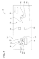
FIG. 2 is a schematic of the automated feeding device of the enteral feeding system; -
FIG. 3 is a section of a valve mechanism of the syringe feeding set in a priming configuration; -
FIG. 4 is a section of the valve mechanism in a metering configuration; -
FIG. 5 is a section of the valve mechanism in a delivering configuration; and -
FIG. 6 is rear perspective of the valve mechanism. - Corresponding reference characters indicate corresponding pans throughout the drawings.
- Referring now to the drawings, an embodiment of an enteral feeding system for enterally feeding a patient, such as a neonate, is generally indicated at 10. In general, the feeding system comprises a feeding set, generally indicated at 12, and an automated feeding device, generally indicated at 14, on which the feeding set is mounted. Overall, the
feeding system 10 is configured to allow for liquid nutrients such as breast milk and/or medicine to be automatically delivered to the patient as either continuous feeding or bolus feeding. - Referring to
FIG. 1 , thefeeding set 12 includes a syringe 16 (broadly, a metering device) and avalve mechanism 18 secured the syringe in communication with anoutlet 19 of the syringe. Thevalve mechanism 18 and thesyringe 16 are removably secured to mounts 20 on theautomated feeding device 14. Themounts 20 define slots (not shown), and thevalve mechanism 18 and thesyringe 16 are slid into these slots to secure the valve mechanism and the syringe to theautomated feeding device 14. Theautomated feeding device 14 may include stops (not shown) or catches (not shown) or other components that releasably engage thevalve mechanism 18 and/or thesyringe 16 to hold the valve mechanism and the syringe in place relative to themounts 20. Thevalve mechanism 18 and thesyringe 16 may be withdrawn from the slots to remove the valve mechanism and the syringe from theautomated feeding device 14. Other ways of securing thevalve mechanism 18 and thesyringe 16 to theautomated feeding device 14 do not depart from the scope of the present invention. - A
plunger 22 of thesyringe 16 is operatively connected to a crank-slider mechanism, generally indicated at 26, of theautomated feeding device 14 to produce reciprocating back and forth movement of the plunger in abarrel 28 of the syringe, as explained in more detail below. Themechanism 26 comprises acrank 30 operatively connected to adriveshaft 32 of motor, such as an electric motor (not shown), inside theautomated feeding device 14 to produce rotational movement of the crank. Opposite ends of a connecting rod orlinkage 34 are operatively, i.e., pivotally, connected to thecrank 30 and theplunger 22 to convert rotational motion of the crank into translational motion of the plunger in thebarrel 28. The connectingrod 34 is releasably secured to theplunger 22 so that thesyringe 16 may be removed from theautomated feeding device 14. For example, the connectingrod 34 and theplunger 22 may include mateable snap-fit connectors that form a hinge. Others connections do not depart from the scope of the present invention. As will be explained below, operation of the crank-slider mechanism, and more specifically the motor of the crank-slider mechanism, is controlled by acontroller 36 located inside the automated feeding device. Other mechanical and/or automated ways of reciprocating theplunger 22 do not depart from the scope of the present invention. Moreover, it is understood that thefeeding set 12 may be used apart from theautomated feeding device 14, and that theplunger 22 may be moved manually, with or without the aid of a mechanical device. - Referring to
FIGS. 1 and3-6 , thevalve mechanism 18 of the illustrated embodiment includes avalve body 38 defining areservoir port 40, afeeding port 42, asyringe port 44 and apriming port 46. Thereservoir port 40 is fluidly connected to a liquid reservoir orcontainer 50 viafirst tubing 52, although the reservoir port and the reservoir may be fluidly connected in other ways. Thefeeding port 42 is fluidly connected to the patient viasecond tubing 54, although the feeding port and the patient may be fluidly connected in other ways. Thesyringe port 44 is fluidly connected to theoutlet 19 of thesyringe 16 via a suitable connection, such as a luer-type connection or other connections. Alternatively, thevalve mechanism 18 and thesyringe 12 may be integrally formed or connected by tubing or in other ways. Finally, thepriming port 46 is in fluid communication with the atmosphere. - A
valve member 58 is rotatable inside thevalve body 38 so that selectedports passage 59 in the valve member. In the illustrated embodiment, thevalve member 58 is a hollow member having an outer wall with a pair of openings 59a, 59b communicating with an interior cavity 59c of the valve member to define theflow passage 59. The two openings 59a, 59b are configured such that the valve member is rotatable to different positions to provide different valve configurations, including a closed configuration (not shown) in which flow through the valve member is blocked, a priming configuration (FIG. 3 ), a metering configuration (FIG. 4 ), and a feeding configuration (FIG. 5 ). It will be understood that thevalve member 58 could be configured to have multiple separate passages arranged such that rotation of the valve member to different positions aligns particular passages with corresponding ports to provide the desired valve configurations (i.e., flow paths). Thevalve mechanism 18 of the illustrated embodiment is similar to the valve mechanism disclosed inU.S. Application Serial No. 10/853,958, filed May 25, 2004 - The
valve member 58 is operatively connected to avalve actuator 60 of theautomated feeding device 14. In the illustrated embodiment, thevalve actuator 60 comprises anoutput shaft 62 of a motor (not shown) in theautomated feeding device 14. A key 64 at the free end of theoutput shaft 62 is sized and shaped for sliding reception in a slot 66 (FIG. 6 ) defined by thevalve member 58 when thevalve mechanism 18 is secured to the automated feeding device. As will be explained below, theactuator 60 rotates thevalve member 58 to configure thevalve mechanism 18 between the various valve configurations explained above. Operation of theactuator 60 is controlled by thecontroller 36 located inside theautomated feeding device 14. Other mechanical and/or automated ways of rotating thevalve member 58 do not depart from the scope of the present invention. Moreover, it is understood that the feeding set 12 may be used apart from theautomated feeding device 14, and thevalve member 58 may be rotated manually, with or without the aid of a mechanical device. - In one embodiment, the
automated feeding device 14 includes apriming sensor 70, in communication with thecontroller 36, for detecting when liquid from theliquid reservoir 50 has completely filled thefirst tubing 52 and/or thevalve member 58. In the illustrated embodiment, the primingsensor 70 includes an optical sensor that detects when liquid is present in thepriming port 46 and sends a signal indicating the same to thecontroller 36. Theoptical sensor 70 is received in an opening orcavity 72 in themount 20 that secures thevalve mechanism 18 to theautomated feeding device 14 so that the sensor is proximate to the primingport 46. The primingsensor 70 may be positioned at other locations on theautomated feeding device 14 to detect when liquid is present in thevalve member 58 and/or thereservoir port 40 without departing from the scope of the present invention. Moreover, sensors other than optical sensors may be used to detect the presence of liquid in thereservoir port 40 and/or thevalve member 58. - In an exemplary use, the feeding set 12 is first mounted on the
automated feeding device 14. Thevalve mechanism 18 is slid intorespective mounts 20 so that the key 64 on theoutput shaft 62 is received in theslot 66 of thevalve disc 58, and thesyringe 16 is also slid into respective mounts. The connectingrod 34 is connected to theplunger 22. Thefirst tubing 52 is connected to thereservoir 50 and thereservoir port 40. Thereservoir 50 is positioned above thereservoir port 40 and may be secured to a stand or an upper surface of theautomated feeding device 14. Thesecond tubing 54 is connected to the feedingport 42 and inserted into the patient for enteral feeding. Initially, thevalve mechanism 18 is configured in the closed configuration so that each of theports - With the feeding set 12 mounted on the
automated feeding device 14, a user selects a feeding protocol of thecontroller 36 using auser interface 74 of theautomated feeding device 14. Thecontroller 36 may be programmed with numerous and various feeding protocols. Two such protocols may be continuous feeding and bolus feeding. In general, a continuous feeding protocol involves delivering a selected amount of liquid nutrients from thereservoir 50 to the patient continuously over a selected period of time. On the other hand, a bolus feeding protocol generally involves delivering a selected amount of liquid nutrients from the reservoir to the patient in a single dose, or effectively, all at once. Thecontroller 36 may be programmed to receive selected parameters from the user interface, including an amount to be delivered and a time period for delivering the liquid. Thecontroller 36 may be programmed in other ways without departing from the scope of the present invention. - After the protocol has been selected and any necessary parameters have been input to the
controller 36, the feeding set 12 is primed. The controller activates the valve actuator motor to turn theactuator 60 and in turn to rotate thevalve disc 58 so that thevalve mechanism 18 is in its priming configuration (FIG. 3 ). In this configuration, thereservoir port 40 is fluidly connected to the primingport 46 via thepassage 59 in the valve member, and the feedingport 42 and thesyringe port 44 are closed. With thereservoir port 40 fluidly connected to the primingport 46 and atmosphere, liquid from the reservoir flows, by gravity, through thefirst tubing 52 toward the reservoir port and thevalve member 58. Thesensor 70 detects the liquid flowing into thevalve member 58 and sends a signal to thecontroller 36 indicating that thevalve mechanism 18 is primed. - When the
controller 36 receives the signal that thevalve mechanism 18 is primed, the controller activates the valve actuator motor to turn theactuator 60, and, in turn, to rotate thevalve member 58 so that the valve mechanism assumes its metering configuration (FIG. 4 ). In the metering configuration, thereservoir port 40 is fluidly connected to thesyringe port 44 via thepassage 59. Initially, theplunger 22 is fully depressed in the barrel 28 (i.e., toward the outlet 19). With thevalve mechanism 18 in the metering configuration, thecontroller 36 activates the crank-slider motor (not shown) to rotate thecrank 30 in a first direction (e.g., clockwise) and retract theplunger 22 in thebarrel 28. As theplunger 28 retracts, liquid is aspirated through thebarrel port 44 and into thebarrel 28 of the syringe. In one example, the amount of liquid aspirated into the barrel, as determined by the operation of the crank-slider 26, is dependent on the protocol selected by the user and/or parameters inputted to thecontroller 36. In a first feeding example, if the protocol and/or input parameters calls for an amount of liquid that is less than the maximum quantity deliverable by thesyringe 16 in a single discharge, then thecontroller 36 turns thecrank 30 until thebarrel 28 fills with a substantially precise, selected quantity of liquid from the reservoir, and then the controller stops the crank. In a second feeding example, thecontroller 36 continues to turn thecrank 30 in the first direction (e.g., clockwise), until the maximum quantity of liquid is aspirated into thebarrel 28, as explained in more detail below. - With the desired quantity of liquid in the
barrel 28, thecontroller 36 activates the actuator motor (not shown) to rotate thevalve member 58 so that thevalve mechanism 18 is in the feeding configuration (FIG. 4 ). In this configuration, thesyringe port 44 is fluidly connected to the feedingport 42 via thepassage 59 in thevalve member 58. In the first feeding example above, thecontroller 36 then turns thecrank 30 in an opposite second direction (e.g., counter-clockwise) to depress theplunger 22 so that the selected quantity of liquid in the syringe is delivered to the patient. The speed at which thecrank 30 is turned, and in effect the speed at which the plunger is depressed, depends on whether the bolus or continuous feeding protocol was selected and the parameters (e.g., amount over time) that were input. In the second feeding example above, thecontroller 36 continues to turn the crank in the same first direction after thevalve mechanism 18 is in the feeding configuration. The configuration and arrangement of the crank-slider 26 is such that rotating thecrank 30 an initial portion of a complete revolution (e.g., 180 degrees) retracts theplunger 22 and continuing to rotate the crank a remainder portion of the complete revolution (e.g., remaining 180 degrees) depresses the plunger. The speed at which thecrank 30 is turned as theplunger 22 depresses, and in effect the speed at which the plunger is depressed, depends on whether the bolus or continuous feeding protocol was selected and the parameters (e.g., amount over time) that were input. - In addition, in a third feeding example, if the protocol and/or input parameters calls for an amount of liquid that is greater than the maximum quantity deliverable by the
syringe 16 in a single discharge such as continuous feeding, thecontroller 36 continuously rotates the crank 30 more than one complete revolution (i.e., more than 360 degrees) and configures thevalve mechanism 18 in the necessary configurations throughout rotation of the crank such that immediately after an initial metered portion of liquid is completely discharged from the syringe, the syringe is reloaded with an appropriate amount of liquid and then discharged as the crank continues to rotate. This cycle of continuously reloading and discharging (i.e., continuously feeding) can continue without re-priming thevalve mechanism 18 until the appropriate amount of liquid has been delivered to the patient. - As will be understood from above disclosure, the
feeding system 10 allows for precise metering and delivery of small amount(s) of liquid nutrient to a patient, such as a neonatal patient. Precise metering and delivery is especially advantageous when feeding a neonatal patient. - Another feature of the illustrated
enteral feeding system 10 allows for the feeding set 12 (more generally, thevalve mechanism 18, and more generally still the first tubing 52) to be automatically primed at the onset of the feeding to minimize or eliminate loss of liquid. In one example, the primingsensor 70 and thecontroller 36 act together to ensure that the feeding set 12 is primed while also preventing the liquid from flowing out the primingport 46 because the priming sensor detects the liquid before the liquid flows out the priming port and upon receiving the signal from priming sensor that thevalve mechanism 18 is primed, thecontroller 36 immediately closes the priming port before liquid can escape through the priming port. This automated priming mechanism reduces waste of the liquid, which may be precious breast milk, and ensures that the system is completely primed so that air is not delivered to the patient along with the liquid. The automated priming mechanism also makes the initial set up of thesystem 10 easier and more time efficient for the operator. - An additional feature is that the crank-
slider mechanism 26 of thefeeding system 10 allows for semi-continuous feeding, such as when thecrank 30 continuously rotates for more than one revolution, without the need to re-prime the system. As discussed above, after initial priming, thevalve mechanism 26 only needs to switch (cycle) between the metering configuration and the feeding configuration to continue feeding after thesyringe 16 has delivered an initial maximum deliverable quantity. Moreover, the speed of thecrank 30 is controllable by the controller to control the rate at which the liquid is feed to the patient. Controlling the rate of feeding allows for both continuous feeding and bolus feeding. - Having described the invention in detail, it will be apparent that modifications and variations are possible without departing from the scope of the invention defined in the appended claims.
- When introducing elements of the present invention or the preferred embodiment(s) thereof, the articles "a", "an", "the" and "said" are intended to mean that there are one or more of the elements. The terms "comprising", "including" and "having" are intended to be inclusive and mean that there may be additional elements other than the listed elements.
- As various changes could be made in the above constructions, products, and methods without departing from the scope of the invention, it is intended that all matter contained in the above description and shown in the accompanying drawings shall be interpreted as illustrative and not in a limiting sense.
Claims (15)
- A valve mechanism for use with a feeding set including a reservoir of liquid and a metering device, the valve mechanism comprising:a valve body including a reservoir port adapted to be fluidly connected to the reservoir, a metering port adapted to be fluidly connected to the metering device, a feeding port adapted to be in fluid communication with the patient, and a priming port in fluid communication with atmosphere;a valve member in the valve body adapted to selectively fluidly connect the reservoir port to the priming port, to fluidly connect the reservoir port to the metering port, and to fluidly connect the metering port to the feeding port.
- A valve mechanism as set forth in claim 1 wherein the valve member is movable to configure the valve mechanism between a priming configuration in which the reservoir port is fluidly connected to the priming port, a metering configuration in which the reservoir port is fluidly connected to the metering port and the priming port is no longer in fluid communication with the reservoir port, and a feeding configuration in which the metering port is fluidly connected to the feeding port and the metering port is no longer in fluid communication with the reservoir port.
- A valve mechanism as set forth in claims 1 or 2 wherein the valve member comprises a rotatable valve member in the valve body.
- A valve mechanism as set forth in any one of claims 1-3 further comprising a priming sensor for detecting liquid in at least one of the reservoir port, the valve member and the priming port.
- A valve mechanism as set forth in any one of claims 1-4 in combination with the feeding set, the feeding set comprising:a reservoir fluidly connected to the reservoir port of the valve mechanism, said reservoir being adapted for holding a quantity of liquid; anda syringe fluidly connected to the syringe port of the valve mechanism for aspirating a quantity of liquid from the reservoir and delivering the quantity of liquid to a patient.
- A valve mechanism as set forth in claim 5 wherein the valve mechanism is operable in a priming configuration to fluidly connect the reservoir to the priming port to prime the valve mechanism, wherein the valve mechanism is operable in a metering configuration to fluidly connect the reservoir to the syringe and to block fluid communication between the reservoir and the priming port, thereby allowing a quantity of liquid to be metered from the reservoir by operating the syringe, and wherein the valve mechanism is operable in a feeding configuration to fluidly connect the syringe to the feeding port and to block fluid communication between the reservoir and the syringe, thereby allowing liquid to be delivered to the patient by operating the syringe.
- A valve mechanism as set forth in any one of claims 1-6 wherein the valve member is cylindrical.
- A valve mechanism as set forth in claims 5 or 6 further comprising a first tubing fluidly connecting the reservoir to the reservoir port of the valve mechanism, and a priming sensor for detecting when liquid from the reservoir has completely filled the first tubing.
- A valve mechanism as set forth in any one of claims 1-8 further comprising a power-driven valve actuator operatively connected to the valve mechanism for configuring the valve mechanism between a priming configuration and a metering configuration.
- A valve mechanism as set forth in claim 9 further comprising a priming sensor disposed to detect liquid in the reservoir port of the valve mechanism, and a controller in communication with the priming sensor and the valve actuator, wherein said priming sensor is adapted to send a signal to the controller indicative of the system being primed when the sensor detects liquid, and wherein in response to receiving the signal from the priming sensor, said controller is adapted to activate the valve actuator to configure the valve mechanism in said metering configuration.
- A method of feeding a nutritional liquid to a patient using an automated feeding device, comprising:connecting a reservoir of nutritional liquid to a valve mechanism through a first tubing;placing the reservoir and the first tubing in fluid communication with a priming port of the valve mechanism so that nutritional liquid in the reservoir flows to the valve mechanism through the first tubing, thereby priming the first tubing and removing air from the reservoir tubing;aspirating a first quantity of nutritional liquid from the reservoir and the first tubing through the valve mechanism and into a syringe of the automated feeding device;dispensing the first quantity of liquid from the syringe through the valve mechanism to the patient;aspirating a second quantity of nutritional liquid from the reservoir and the first tubing through the valve mechanism and into the syringe without re-priming the first tubing, whereby feeding from the syringe to the patient can be carried out semi-continuously.
- A method as set forth in claim 11 further comprising dispensing the second quantity from the syringe through the valve mechanism to the patient.
- A method as set forth in claim 11 or 12 further comprising aspirating and dispensing third and subsequent quantities of nutritional liquid without re-priming the first tubing.
- A method as set forth in any one of claims 11-13 further comprising blocking fluid communication between the reservoir, the first tubing and the priming port when nutritional liquid is detected in the valve mechanism.
- A method as set forth in any one of claims 11-14 wherein the nutritional liquid is sensed by a priming sensor which sends a signal to a controller in communication with the sensor to close the priming port before the liquid can escape.
Applications Claiming Priority (1)
| Application Number | Priority Date | Filing Date | Title |
|---|---|---|---|
| US12/368,526 US8052656B2 (en) | 2009-02-10 | 2009-02-10 | Enteral feeding system |
Publications (3)
| Publication Number | Publication Date |
|---|---|
| EP2216070A2 true EP2216070A2 (en) | 2010-08-11 |
| EP2216070A3 EP2216070A3 (en) | 2012-10-10 |
| EP2216070B1 EP2216070B1 (en) | 2021-07-07 |
Family
ID=42124619
Family Applications (1)
| Application Number | Title | Priority Date | Filing Date |
|---|---|---|---|
| EP10153074.9A Active EP2216070B1 (en) | 2009-02-10 | 2010-02-09 | Enteral feeding system |
Country Status (6)
| Country | Link |
|---|---|
| US (1) | US8052656B2 (en) |
| EP (1) | EP2216070B1 (en) |
| CN (1) | CN101797419B (en) |
| AU (1) | AU2010200457B2 (en) |
| CA (1) | CA2692057C (en) |
| IL (1) | IL203726A0 (en) |
Families Citing this family (21)
| Publication number | Priority date | Publication date | Assignee | Title |
|---|---|---|---|---|
| EP2303362B1 (en) * | 2008-07-18 | 2019-06-05 | Becton, Dickinson and Company | Dual chamber and gear pump assembly for a high pressure delivery system |
| US8733736B2 (en) * | 2009-05-27 | 2014-05-27 | Carefusion 303, Inc. | Intravenous piston pump disposable and mechanism |
| US20120291811A1 (en) * | 2011-05-20 | 2012-11-22 | Dabney James H | Feeding Tube Cleaning Devices and Methods |
| RU2618902C2 (en) * | 2011-12-08 | 2017-05-11 | Алькон Рисерч, Лтд. | Selectively moved valves for aspiration and irrigation loops |
| US9549850B2 (en) | 2013-04-26 | 2017-01-24 | Novartis Ag | Partial venting system for occlusion surge mitigation |
| US10292908B2 (en) | 2014-08-01 | 2019-05-21 | Medela Holding Ag | Neonatal enteral feeding system |
| TWI574799B (en) * | 2015-01-26 | 2017-03-21 | hong-ping Li | Automatic feeding system for infants and young children and its implementation |
| CN104546502B (en) * | 2015-01-26 | 2017-09-12 | 深圳大学附属医院 | A kind of automatic feeding system of infant and its implementation |
| CA3123388A1 (en) | 2018-06-29 | 2020-01-02 | Generica Medical International, Inc. | Enteral feeding systems and methods |
| US11266574B2 (en) * | 2018-08-27 | 2022-03-08 | Avent, Inc. | Blenderized diet and/or bolus delivery manual pump |
| WO2020167703A1 (en) * | 2019-02-12 | 2020-08-20 | Amgen Inc. | Continuous dosing systems and approaches |
| USD920504S1 (en) | 2019-07-01 | 2021-05-25 | Medline Industries, Inc. | Valve |
| US11110036B2 (en) * | 2019-07-01 | 2021-09-07 | Medline Industries, Inc. | Feeding set and enteral feeding pump assembly |
| CN110215403B (en) * | 2019-07-11 | 2024-12-10 | 扬州市中医院 | Multifunctional liquid feeding connector and feeding device |
| CN111514029B (en) * | 2020-04-29 | 2022-06-14 | 中国医学科学院北京协和医院 | Pressure-adjustable enteral nutrition input pump |
| CN113057893A (en) * | 2021-03-12 | 2021-07-02 | 郑州大学第一附属医院 | Feeding equipment for intensive care unit |
| US11963934B2 (en) * | 2021-05-27 | 2024-04-23 | Zevex, Inc. | Flow valve for use with enteral feeding pump flush module |
| US12589233B2 (en) * | 2021-09-23 | 2026-03-31 | Engineered Medical Systems, Inc. | Ball valve for use in a respiration circuit and a respiration circuit including a ball valve |
| WO2024102340A1 (en) * | 2022-11-07 | 2024-05-16 | New York University | System and methods for neonatal gastric tube feeding and venting |
| CN116712338B (en) * | 2023-05-29 | 2024-03-19 | 中国人民解放军总医院第一医学中心 | Self-help nasal feeding device |
| US12560161B2 (en) * | 2024-03-07 | 2026-02-24 | Kpr U.S., Llc | Fluid delivery |
Family Cites Families (31)
| Publication number | Priority date | Publication date | Assignee | Title |
|---|---|---|---|---|
| US297794A (en) | 1884-04-29 | Island | ||
| US2032723A (en) | 1934-05-05 | 1936-03-03 | Carl E Schweser | Serum injecting outfit |
| US2644450A (en) | 1952-02-06 | 1953-07-07 | Josephine E Krewson | Holder and operator for hypodermic syringes |
| IL33528A (en) | 1968-12-27 | 1975-08-31 | Pall Corp | Sterile disposable medicament administration system |
| US3834372A (en) * | 1973-01-12 | 1974-09-10 | S Turney | Disposable manifold with atmospheric vent |
| US3957082A (en) * | 1974-09-26 | 1976-05-18 | Arbrook, Inc. | Six-way stopcock |
| US4253501A (en) | 1979-11-09 | 1981-03-03 | Ims Limited | Transfer system |
| US5005604A (en) * | 1984-07-13 | 1991-04-09 | Aslanian Jerry L | Flow control device for administration of intravenous fluids |
| IE56756B1 (en) * | 1984-07-13 | 1991-12-04 | Master Medical Corp | Flow control device for administration of intravenous fluids |
| US5318539A (en) | 1986-10-17 | 1994-06-07 | Alexander G. B. O'Neil | Liquid feeding apparatus utilizing capillary tubing, and syringe driver |
| US4904245A (en) * | 1988-12-07 | 1990-02-27 | Allen S. Chen | Surgical valve assembly for urinary bladder irrigation and drainage |
| US5002528A (en) | 1989-12-15 | 1991-03-26 | Aubrey Palestrant | Percutaneous irrigation and drainage system |
| US5466228A (en) | 1991-01-25 | 1995-11-14 | California State University, Fresno Foundation | Fluid control apparatus |
| US5356375A (en) | 1992-04-06 | 1994-10-18 | Namic U.S.A. Corporation | Positive pressure fluid delivery and waste removal system |
| US5439452A (en) | 1994-01-31 | 1995-08-08 | Children's Medical Ventures, Inc. | Limit stop valve infusion device |
| US5533978A (en) | 1994-11-07 | 1996-07-09 | Teirstein; Paul S. | Method and apparatus for uninterrupted delivery of radiographic dye |
| US6656157B1 (en) | 1995-04-20 | 2003-12-02 | Acist Medical Systems, Inc. | Infinitely refillable syringe |
| US5876378A (en) | 1996-09-20 | 1999-03-02 | Mbadugha; Joseph O. | Apparatus and method for injecting liquids into patients |
| US5807312A (en) | 1997-05-23 | 1998-09-15 | Dzwonkiewicz; Mark R. | Bolus pump apparatus |
| US6059747A (en) | 1997-07-16 | 2000-05-09 | Medex, Inc. | Syringe pump infusion control set |
| IL128016A0 (en) * | 1999-01-12 | 1999-11-30 | Elcam Plastic Kibbutz Bar Am | Blood sampling device |
| GB0001309D0 (en) | 2000-01-20 | 2000-03-08 | Nestle Sa | Valve arrangement |
| FR2804609B1 (en) * | 2000-02-08 | 2002-08-30 | Sedat | DISTRIBUTION DEVICE FOR A MEDICAL FLUID TRANSPORT NETWORK |
| KR100797144B1 (en) | 2001-06-01 | 2008-01-22 | 아이-플로우 코포레이션 | Massive bolus device and method |
| JP3809114B2 (en) * | 2001-11-05 | 2006-08-16 | スーガン株式会社 | Channel switching device and contrast medium injection tube used in the device |
| US6953450B2 (en) | 2002-08-22 | 2005-10-11 | Baxa Corporation | Apparatus and method for administration of IV liquid medication and IV flush solutions |
| US7128727B2 (en) * | 2002-09-30 | 2006-10-31 | Flaherty J Christopher | Components and methods for patient infusion device |
| US7092797B2 (en) * | 2004-05-25 | 2006-08-15 | Sherwood Services Ag | Flow monitoring system for a flow control apparatus |
| US20050267417A1 (en) * | 2004-05-25 | 2005-12-01 | Secrest Dean J | Irrigating biopsy inlet valve |
| US20070118078A1 (en) | 2005-11-18 | 2007-05-24 | Mcnally David J | Method and apparatus for controlled feeding of an infant |
| US7757891B2 (en) * | 2007-03-14 | 2010-07-20 | Chemflow Systems, Inc. | Method and apparatus for providing constant liquid rates and dispensing precisely repeatable liquid volumes |
-
2009
- 2009-02-10 US US12/368,526 patent/US8052656B2/en active Active
-
2010
- 2010-02-03 CA CA2692057A patent/CA2692057C/en active Active
- 2010-02-04 IL IL203726A patent/IL203726A0/en unknown
- 2010-02-09 AU AU2010200457A patent/AU2010200457B2/en active Active
- 2010-02-09 EP EP10153074.9A patent/EP2216070B1/en active Active
- 2010-02-10 CN CN201010116515XA patent/CN101797419B/en active Active
Also Published As
| Publication number | Publication date |
|---|---|
| US8052656B2 (en) | 2011-11-08 |
| US20100204645A1 (en) | 2010-08-12 |
| CN101797419B (en) | 2013-10-23 |
| EP2216070B1 (en) | 2021-07-07 |
| CN101797419A (en) | 2010-08-11 |
| CA2692057A1 (en) | 2010-08-10 |
| AU2010200457B2 (en) | 2014-08-14 |
| AU2010200457A1 (en) | 2010-08-26 |
| EP2216070A3 (en) | 2012-10-10 |
| IL203726A0 (en) | 2010-11-30 |
| CA2692057C (en) | 2014-01-28 |
Similar Documents
| Publication | Publication Date | Title |
|---|---|---|
| US8052656B2 (en) | Enteral feeding system | |
| CN112888414B (en) | Medical Pump Systems | |
| US20080208117A1 (en) | System for delivering solutions and reducing waste | |
| JP5669458B2 (en) | Disposable cartridge for storing and delivering two-component dental impression material | |
| JP2001501504A (en) | Working cylinder | |
| US20170319790A1 (en) | Drug Delivery Device with Air-in-Cartridge Safety Feature | |
| JPH11513586A (en) | Configuration of electronically controlled syringe | |
| JP2005537116A (en) | Dosing device with temperature sensor | |
| CN109715229A (en) | Suction and conveying device with driving unit and connector | |
| JP2022501130A5 (en) | ||
| CA3092686C (en) | Medical infusion pump for delivery of a fluid | |
| JPH10309314A (en) | Medical liquid dosing device | |
| JPH10309314A5 (en) | ||
| CN110731328A (en) | Dispensing device and dispensing system | |
| HUP0102219A2 (en) | Metered dose infusion pump and method | |
| US20100234812A1 (en) | Fluid Recovery System | |
| KR20220151117A (en) | Device for dispensing a fluid drop-by-drop | |
| RU2745231C9 (en) | Spray inhaler with preparation and storage functions | |
| CN119584998A (en) | Drug delivery device box and drug delivery device | |
| WO2022118003A1 (en) | Pump | |
| HK1139457B (en) | Metering device for an infusion system | |
| MXPA98000970A (en) | Device for the dosage of medicine liquids | |
| WO2020018874A1 (en) | Feeding system for gastric tube patients | |
| HK1139457A1 (en) | Metering device for an infusion system |
Legal Events
| Date | Code | Title | Description |
|---|---|---|---|
| PUAI | Public reference made under article 153(3) epc to a published international application that has entered the european phase |
Free format text: ORIGINAL CODE: 0009012 |
|
| AK | Designated contracting states |
Kind code of ref document: A2 Designated state(s): AT BE BG CH CY CZ DE DK EE ES FI FR GB GR HR HU IE IS IT LI LT LU LV MC MK MT NL NO PL PT RO SE SI SK SM TR |
|
| AX | Request for extension of the european patent |
Extension state: AL BA RS |
|
| PUAL | Search report despatched |
Free format text: ORIGINAL CODE: 0009013 |
|
| AK | Designated contracting states |
Kind code of ref document: A3 Designated state(s): AT BE BG CH CY CZ DE DK EE ES FI FR GB GR HR HU IE IS IT LI LT LU LV MC MK MT NL NO PL PT RO SE SI SK SM TR |
|
| AX | Request for extension of the european patent |
Extension state: AL BA RS |
|
| RIC1 | Information provided on ipc code assigned before grant |
Ipc: A61M 39/22 20060101AFI20120904BHEP Ipc: A61M 5/00 20060101ALN20120904BHEP |
|
| RAP1 | Party data changed (applicant data changed or rights of an application transferred) |
Owner name: COVIDIEN LP |
|
| 17P | Request for examination filed |
Effective date: 20130405 |
|
| STAA | Information on the status of an ep patent application or granted ep patent |
Free format text: STATUS: EXAMINATION IS IN PROGRESS |
|
| 17Q | First examination report despatched |
Effective date: 20170918 |
|
| RAP1 | Party data changed (applicant data changed or rights of an application transferred) |
Owner name: KPR U.S., LLC |
|
| GRAP | Despatch of communication of intention to grant a patent |
Free format text: ORIGINAL CODE: EPIDOSNIGR1 |
|
| STAA | Information on the status of an ep patent application or granted ep patent |
Free format text: STATUS: GRANT OF PATENT IS INTENDED |
|
| INTG | Intention to grant announced |
Effective date: 20210118 |
|
| GRAS | Grant fee paid |
Free format text: ORIGINAL CODE: EPIDOSNIGR3 |
|
| GRAA | (expected) grant |
Free format text: ORIGINAL CODE: 0009210 |
|
| STAA | Information on the status of an ep patent application or granted ep patent |
Free format text: STATUS: THE PATENT HAS BEEN GRANTED |
|
| AK | Designated contracting states |
Kind code of ref document: B1 Designated state(s): AT BE BG CH CY CZ DE DK EE ES FI FR GB GR HR HU IE IS IT LI LT LU LV MC MK MT NL NO PL PT RO SE SI SK SM TR |
|
| REG | Reference to a national code |
Ref country code: GB Ref legal event code: FG4D |
|
| REG | Reference to a national code |
Ref country code: AT Ref legal event code: REF Ref document number: 1407959 Country of ref document: AT Kind code of ref document: T Effective date: 20210715 |
|
| REG | Reference to a national code |
Ref country code: DE Ref legal event code: R096 Ref document number: 602010067221 Country of ref document: DE |
|
| REG | Reference to a national code |
Ref country code: IE Ref legal event code: FG4D |
|
| REG | Reference to a national code |
Ref country code: LT Ref legal event code: MG9D |
|
| REG | Reference to a national code |
Ref country code: NL Ref legal event code: MP Effective date: 20210707 |
|
| REG | Reference to a national code |
Ref country code: AT Ref legal event code: MK05 Ref document number: 1407959 Country of ref document: AT Kind code of ref document: T Effective date: 20210707 |
|
| PG25 | Lapsed in a contracting state [announced via postgrant information from national office to epo] |
Ref country code: NO Free format text: LAPSE BECAUSE OF FAILURE TO SUBMIT A TRANSLATION OF THE DESCRIPTION OR TO PAY THE FEE WITHIN THE PRESCRIBED TIME-LIMIT Effective date: 20211007 Ref country code: PT Free format text: LAPSE BECAUSE OF FAILURE TO SUBMIT A TRANSLATION OF THE DESCRIPTION OR TO PAY THE FEE WITHIN THE PRESCRIBED TIME-LIMIT Effective date: 20211108 Ref country code: NL Free format text: LAPSE BECAUSE OF FAILURE TO SUBMIT A TRANSLATION OF THE DESCRIPTION OR TO PAY THE FEE WITHIN THE PRESCRIBED TIME-LIMIT Effective date: 20210707 Ref country code: ES Free format text: LAPSE BECAUSE OF FAILURE TO SUBMIT A TRANSLATION OF THE DESCRIPTION OR TO PAY THE FEE WITHIN THE PRESCRIBED TIME-LIMIT Effective date: 20210707 Ref country code: FI Free format text: LAPSE BECAUSE OF FAILURE TO SUBMIT A TRANSLATION OF THE DESCRIPTION OR TO PAY THE FEE WITHIN THE PRESCRIBED TIME-LIMIT Effective date: 20210707 Ref country code: BG Free format text: LAPSE BECAUSE OF FAILURE TO SUBMIT A TRANSLATION OF THE DESCRIPTION OR TO PAY THE FEE WITHIN THE PRESCRIBED TIME-LIMIT Effective date: 20211007 Ref country code: AT Free format text: LAPSE BECAUSE OF FAILURE TO SUBMIT A TRANSLATION OF THE DESCRIPTION OR TO PAY THE FEE WITHIN THE PRESCRIBED TIME-LIMIT Effective date: 20210707 Ref country code: LT Free format text: LAPSE BECAUSE OF FAILURE TO SUBMIT A TRANSLATION OF THE DESCRIPTION OR TO PAY THE FEE WITHIN THE PRESCRIBED TIME-LIMIT Effective date: 20210707 Ref country code: SE Free format text: LAPSE BECAUSE OF FAILURE TO SUBMIT A TRANSLATION OF THE DESCRIPTION OR TO PAY THE FEE WITHIN THE PRESCRIBED TIME-LIMIT Effective date: 20210707 Ref country code: HR Free format text: LAPSE BECAUSE OF FAILURE TO SUBMIT A TRANSLATION OF THE DESCRIPTION OR TO PAY THE FEE WITHIN THE PRESCRIBED TIME-LIMIT Effective date: 20210707 |
|
| PG25 | Lapsed in a contracting state [announced via postgrant information from national office to epo] |
Ref country code: PL Free format text: LAPSE BECAUSE OF FAILURE TO SUBMIT A TRANSLATION OF THE DESCRIPTION OR TO PAY THE FEE WITHIN THE PRESCRIBED TIME-LIMIT Effective date: 20210707 Ref country code: LV Free format text: LAPSE BECAUSE OF FAILURE TO SUBMIT A TRANSLATION OF THE DESCRIPTION OR TO PAY THE FEE WITHIN THE PRESCRIBED TIME-LIMIT Effective date: 20210707 Ref country code: GR Free format text: LAPSE BECAUSE OF FAILURE TO SUBMIT A TRANSLATION OF THE DESCRIPTION OR TO PAY THE FEE WITHIN THE PRESCRIBED TIME-LIMIT Effective date: 20211008 |
|
| REG | Reference to a national code |
Ref country code: DE Ref legal event code: R097 Ref document number: 602010067221 Country of ref document: DE |
|
| PG25 | Lapsed in a contracting state [announced via postgrant information from national office to epo] |
Ref country code: DK Free format text: LAPSE BECAUSE OF FAILURE TO SUBMIT A TRANSLATION OF THE DESCRIPTION OR TO PAY THE FEE WITHIN THE PRESCRIBED TIME-LIMIT Effective date: 20210707 |
|
| PLBE | No opposition filed within time limit |
Free format text: ORIGINAL CODE: 0009261 |
|
| STAA | Information on the status of an ep patent application or granted ep patent |
Free format text: STATUS: NO OPPOSITION FILED WITHIN TIME LIMIT |
|
| PG25 | Lapsed in a contracting state [announced via postgrant information from national office to epo] |
Ref country code: SM Free format text: LAPSE BECAUSE OF FAILURE TO SUBMIT A TRANSLATION OF THE DESCRIPTION OR TO PAY THE FEE WITHIN THE PRESCRIBED TIME-LIMIT Effective date: 20210707 Ref country code: SK Free format text: LAPSE BECAUSE OF FAILURE TO SUBMIT A TRANSLATION OF THE DESCRIPTION OR TO PAY THE FEE WITHIN THE PRESCRIBED TIME-LIMIT Effective date: 20210707 Ref country code: RO Free format text: LAPSE BECAUSE OF FAILURE TO SUBMIT A TRANSLATION OF THE DESCRIPTION OR TO PAY THE FEE WITHIN THE PRESCRIBED TIME-LIMIT Effective date: 20210707 Ref country code: EE Free format text: LAPSE BECAUSE OF FAILURE TO SUBMIT A TRANSLATION OF THE DESCRIPTION OR TO PAY THE FEE WITHIN THE PRESCRIBED TIME-LIMIT Effective date: 20210707 Ref country code: CZ Free format text: LAPSE BECAUSE OF FAILURE TO SUBMIT A TRANSLATION OF THE DESCRIPTION OR TO PAY THE FEE WITHIN THE PRESCRIBED TIME-LIMIT Effective date: 20210707 |
|
| 26N | No opposition filed |
Effective date: 20220408 |
|
| PG25 | Lapsed in a contracting state [announced via postgrant information from national office to epo] |
Ref country code: IT Free format text: LAPSE BECAUSE OF FAILURE TO SUBMIT A TRANSLATION OF THE DESCRIPTION OR TO PAY THE FEE WITHIN THE PRESCRIBED TIME-LIMIT Effective date: 20210707 |
|
| PG25 | Lapsed in a contracting state [announced via postgrant information from national office to epo] |
Ref country code: MC Free format text: LAPSE BECAUSE OF FAILURE TO SUBMIT A TRANSLATION OF THE DESCRIPTION OR TO PAY THE FEE WITHIN THE PRESCRIBED TIME-LIMIT Effective date: 20210707 |
|
| REG | Reference to a national code |
Ref country code: CH Ref legal event code: PL |
|
| REG | Reference to a national code |
Ref country code: BE Ref legal event code: MM Effective date: 20220228 |
|
| PG25 | Lapsed in a contracting state [announced via postgrant information from national office to epo] |
Ref country code: LU Free format text: LAPSE BECAUSE OF NON-PAYMENT OF DUE FEES Effective date: 20220209 |
|
| PG25 | Lapsed in a contracting state [announced via postgrant information from national office to epo] |
Ref country code: LI Free format text: LAPSE BECAUSE OF NON-PAYMENT OF DUE FEES Effective date: 20220228 Ref country code: IE Free format text: LAPSE BECAUSE OF NON-PAYMENT OF DUE FEES Effective date: 20220209 Ref country code: CH Free format text: LAPSE BECAUSE OF NON-PAYMENT OF DUE FEES Effective date: 20220228 |
|
| PG25 | Lapsed in a contracting state [announced via postgrant information from national office to epo] |
Ref country code: BE Free format text: LAPSE BECAUSE OF NON-PAYMENT OF DUE FEES Effective date: 20220228 |
|
| P01 | Opt-out of the competence of the unified patent court (upc) registered |
Effective date: 20230522 |
|
| PG25 | Lapsed in a contracting state [announced via postgrant information from national office to epo] |
Ref country code: HU Free format text: LAPSE BECAUSE OF FAILURE TO SUBMIT A TRANSLATION OF THE DESCRIPTION OR TO PAY THE FEE WITHIN THE PRESCRIBED TIME-LIMIT; INVALID AB INITIO Effective date: 20100209 |
|
| PG25 | Lapsed in a contracting state [announced via postgrant information from national office to epo] |
Ref country code: MK Free format text: LAPSE BECAUSE OF FAILURE TO SUBMIT A TRANSLATION OF THE DESCRIPTION OR TO PAY THE FEE WITHIN THE PRESCRIBED TIME-LIMIT Effective date: 20210707 Ref country code: CY Free format text: LAPSE BECAUSE OF FAILURE TO SUBMIT A TRANSLATION OF THE DESCRIPTION OR TO PAY THE FEE WITHIN THE PRESCRIBED TIME-LIMIT Effective date: 20210707 |
|
| PG25 | Lapsed in a contracting state [announced via postgrant information from national office to epo] |
Ref country code: TR Free format text: LAPSE BECAUSE OF FAILURE TO SUBMIT A TRANSLATION OF THE DESCRIPTION OR TO PAY THE FEE WITHIN THE PRESCRIBED TIME-LIMIT Effective date: 20210707 |
|
| PG25 | Lapsed in a contracting state [announced via postgrant information from national office to epo] |
Ref country code: MT Free format text: LAPSE BECAUSE OF FAILURE TO SUBMIT A TRANSLATION OF THE DESCRIPTION OR TO PAY THE FEE WITHIN THE PRESCRIBED TIME-LIMIT Effective date: 20210707 |
|
| PGFP | Annual fee paid to national office [announced via postgrant information from national office to epo] |
Ref country code: GB Payment date: 20260227 Year of fee payment: 17 |
|
| PGFP | Annual fee paid to national office [announced via postgrant information from national office to epo] |
Ref country code: DE Payment date: 20260227 Year of fee payment: 17 |
|
| PGFP | Annual fee paid to national office [announced via postgrant information from national office to epo] |
Ref country code: FR Payment date: 20260225 Year of fee payment: 17 |