EP2215975A1 - Fenestrated suture anchor for knotless fixation of tissue - Google Patents
Fenestrated suture anchor for knotless fixation of tissue Download PDFInfo
- Publication number
- EP2215975A1 EP2215975A1 EP10250217A EP10250217A EP2215975A1 EP 2215975 A1 EP2215975 A1 EP 2215975A1 EP 10250217 A EP10250217 A EP 10250217A EP 10250217 A EP10250217 A EP 10250217A EP 2215975 A1 EP2215975 A1 EP 2215975A1
- Authority
- EP
- European Patent Office
- Prior art keywords
- suture
- implant
- anchor
- swivel
- bone
- Prior art date
- Legal status (The legal status is an assumption and is not a legal conclusion. Google has not performed a legal analysis and makes no representation as to the accuracy of the status listed.)
- Ceased
Links
- 239000007943 implant Substances 0.000 claims abstract description 78
- 238000003780 insertion Methods 0.000 claims description 9
- 230000037431 insertion Effects 0.000 claims description 9
- 210000000988 bone and bone Anatomy 0.000 abstract description 72
- 210000001519 tissue Anatomy 0.000 abstract description 26
- 210000000513 rotator cuff Anatomy 0.000 abstract description 19
- 230000035876 healing Effects 0.000 abstract description 8
- 210000004369 blood Anatomy 0.000 abstract description 4
- 239000008280 blood Substances 0.000 abstract description 4
- 230000037361 pathway Effects 0.000 abstract description 4
- 230000001737 promoting effect Effects 0.000 abstract description 3
- 238000000034 method Methods 0.000 description 20
- JTIGKVIOEQASGT-UHFFFAOYSA-N proquazone Chemical compound N=1C(=O)N(C(C)C)C2=CC(C)=CC=C2C=1C1=CC=CC=C1 JTIGKVIOEQASGT-UHFFFAOYSA-N 0.000 description 19
- 239000000463 material Substances 0.000 description 15
- 210000002435 tendon Anatomy 0.000 description 11
- 230000012010 growth Effects 0.000 description 9
- 210000004872 soft tissue Anatomy 0.000 description 7
- 210000003813 thumb Anatomy 0.000 description 7
- 241000287107 Passer Species 0.000 description 5
- 238000009434 installation Methods 0.000 description 5
- 230000014759 maintenance of location Effects 0.000 description 5
- 239000003102 growth factor Substances 0.000 description 4
- 210000003041 ligament Anatomy 0.000 description 4
- 230000017423 tissue regeneration Effects 0.000 description 4
- RTAQQCXQSZGOHL-UHFFFAOYSA-N Titanium Chemical compound [Ti] RTAQQCXQSZGOHL-UHFFFAOYSA-N 0.000 description 3
- 230000002421 anti-septic effect Effects 0.000 description 3
- 230000000740 bleeding effect Effects 0.000 description 3
- 210000003414 extremity Anatomy 0.000 description 3
- 229910052751 metal Inorganic materials 0.000 description 3
- 239000002184 metal Substances 0.000 description 3
- 238000001356 surgical procedure Methods 0.000 description 3
- 229910052719 titanium Inorganic materials 0.000 description 3
- 239000010936 titanium Substances 0.000 description 3
- VTYYLEPIZMXCLO-UHFFFAOYSA-L Calcium carbonate Chemical compound [Ca+2].[O-]C([O-])=O VTYYLEPIZMXCLO-UHFFFAOYSA-L 0.000 description 2
- 101800003838 Epidermal growth factor Proteins 0.000 description 2
- 108090000723 Insulin-Like Growth Factor I Proteins 0.000 description 2
- 102000010780 Platelet-Derived Growth Factor Human genes 0.000 description 2
- 108010038512 Platelet-Derived Growth Factor Proteins 0.000 description 2
- 229920000954 Polyglycolide Polymers 0.000 description 2
- 102100033237 Pro-epidermal growth factor Human genes 0.000 description 2
- 241000239226 Scorpiones Species 0.000 description 2
- 102000013275 Somatomedins Human genes 0.000 description 2
- 229910001069 Ti alloy Inorganic materials 0.000 description 2
- 102000004887 Transforming Growth Factor beta Human genes 0.000 description 2
- 108090001012 Transforming Growth Factor beta Proteins 0.000 description 2
- 238000004873 anchoring Methods 0.000 description 2
- 230000003115 biocidal effect Effects 0.000 description 2
- 230000015572 biosynthetic process Effects 0.000 description 2
- 229940116977 epidermal growth factor Drugs 0.000 description 2
- 210000002758 humerus Anatomy 0.000 description 2
- 239000000314 lubricant Substances 0.000 description 2
- 239000000203 mixture Substances 0.000 description 2
- 210000004623 platelet-rich plasma Anatomy 0.000 description 2
- 229920001432 poly(L-lactide) Polymers 0.000 description 2
- 239000004633 polyglycolic acid Substances 0.000 description 2
- 229950008885 polyglycolic acid Drugs 0.000 description 2
- 238000010079 rubber tapping Methods 0.000 description 2
- 239000007787 solid Substances 0.000 description 2
- ZRKFYGHZFMAOKI-QMGMOQQFSA-N tgfbeta Chemical compound C([C@H](NC(=O)[C@H](C(C)C)NC(=O)CNC(=O)[C@H](CCC(O)=O)NC(=O)[C@H](CCCNC(N)=N)NC(=O)[C@H](CC(N)=O)NC(=O)[C@H](CC(C)C)NC(=O)[C@H]([C@@H](C)O)NC(=O)[C@H](CCC(O)=O)NC(=O)[C@H]([C@@H](C)O)NC(=O)[C@H](CC(C)C)NC(=O)CNC(=O)[C@H](C)NC(=O)[C@H](CO)NC(=O)[C@H](CCC(N)=O)NC(=O)[C@@H](NC(=O)[C@H](C)NC(=O)[C@H](C)NC(=O)[C@@H](NC(=O)[C@H](CC(C)C)NC(=O)[C@@H](N)CCSC)C(C)C)[C@@H](C)CC)C(=O)N[C@@H]([C@@H](C)O)C(=O)N[C@@H](C(C)C)C(=O)N[C@@H](CC=1C=CC=CC=1)C(=O)N[C@@H](C)C(=O)N1[C@@H](CCC1)C(=O)N[C@@H]([C@@H](C)O)C(=O)N[C@@H](CC(N)=O)C(=O)N[C@@H](CCC(O)=O)C(=O)N[C@@H](C)C(=O)N[C@@H](CC=1C=CC=CC=1)C(=O)N[C@@H](CCCNC(N)=N)C(=O)N[C@@H](C)C(=O)N[C@@H](CC(C)C)C(=O)N1[C@@H](CCC1)C(=O)N1[C@@H](CCC1)C(=O)N[C@@H](CCCNC(N)=N)C(=O)N[C@@H](CCC(O)=O)C(=O)N[C@@H](CCCNC(N)=N)C(=O)N[C@@H](CO)C(=O)N[C@@H](CCCNC(N)=N)C(=O)N[C@@H](CC(C)C)C(=O)N[C@@H](CC(C)C)C(O)=O)C1=CC=C(O)C=C1 ZRKFYGHZFMAOKI-QMGMOQQFSA-N 0.000 description 2
- VBEQCZHXXJYVRD-GACYYNSASA-N uroanthelone Chemical compound C([C@@H](C(=O)N[C@H](C(=O)N[C@@H](CS)C(=O)N[C@@H](CC(N)=O)C(=O)N[C@@H](CS)C(=O)N[C@H](C(=O)N[C@@H]([C@@H](C)CC)C(=O)NCC(=O)N[C@@H](CC=1C=CC(O)=CC=1)C(=O)N[C@@H](CO)C(=O)NCC(=O)N[C@@H](CC(O)=O)C(=O)N[C@@H](CCCNC(N)=N)C(=O)N[C@@H](CS)C(=O)N[C@@H](CCC(N)=O)C(=O)N[C@@H]([C@@H](C)O)C(=O)N[C@@H](CCCNC(N)=N)C(=O)N[C@@H](CC(O)=O)C(=O)N[C@@H](CC(C)C)C(=O)N[C@@H](CCCNC(N)=N)C(=O)N[C@@H](CC=1C2=CC=CC=C2NC=1)C(=O)N[C@@H](CC=1C2=CC=CC=C2NC=1)C(=O)N[C@@H](CCC(O)=O)C(=O)N[C@@H](CC(C)C)C(=O)N[C@@H](CCCNC(N)=N)C(O)=O)C(C)C)[C@@H](C)O)NC(=O)[C@H](CO)NC(=O)[C@H](CC(O)=O)NC(=O)[C@H](CC(C)C)NC(=O)[C@H](CO)NC(=O)[C@H](CCC(O)=O)NC(=O)[C@@H](NC(=O)[C@H](CC=1NC=NC=1)NC(=O)[C@H](CCSC)NC(=O)[C@H](CS)NC(=O)[C@@H](NC(=O)CNC(=O)CNC(=O)[C@H](CC(N)=O)NC(=O)[C@H](CC(C)C)NC(=O)[C@H](CS)NC(=O)[C@H](CC=1C=CC(O)=CC=1)NC(=O)CNC(=O)[C@H](CC(O)=O)NC(=O)[C@H](CC=1C=CC(O)=CC=1)NC(=O)[C@H](CO)NC(=O)[C@H](CO)NC(=O)[C@H]1N(CCC1)C(=O)[C@H](CS)NC(=O)CNC(=O)[C@H]1N(CCC1)C(=O)[C@H](CC=1C=CC(O)=CC=1)NC(=O)[C@H](CO)NC(=O)[C@@H](N)CC(N)=O)C(C)C)[C@@H](C)CC)C1=CC=C(O)C=C1 VBEQCZHXXJYVRD-GACYYNSASA-N 0.000 description 2
- KIUKXJAPPMFGSW-DNGZLQJQSA-N (2S,3S,4S,5R,6R)-6-[(2S,3R,4R,5S,6R)-3-Acetamido-2-[(2S,3S,4R,5R,6R)-6-[(2R,3R,4R,5S,6R)-3-acetamido-2,5-dihydroxy-6-(hydroxymethyl)oxan-4-yl]oxy-2-carboxy-4,5-dihydroxyoxan-3-yl]oxy-5-hydroxy-6-(hydroxymethyl)oxan-4-yl]oxy-3,4,5-trihydroxyoxane-2-carboxylic acid Chemical compound CC(=O)N[C@H]1[C@H](O)O[C@H](CO)[C@@H](O)[C@@H]1O[C@H]1[C@H](O)[C@@H](O)[C@H](O[C@H]2[C@@H]([C@@H](O[C@H]3[C@@H]([C@@H](O)[C@H](O)[C@H](O3)C(O)=O)O)[C@H](O)[C@@H](CO)O2)NC(C)=O)[C@@H](C(O)=O)O1 KIUKXJAPPMFGSW-DNGZLQJQSA-N 0.000 description 1
- 102100028728 Bone morphogenetic protein 1 Human genes 0.000 description 1
- 108090000654 Bone morphogenetic protein 1 Proteins 0.000 description 1
- 241001631457 Cannula Species 0.000 description 1
- 206010011985 Decubitus ulcer Diseases 0.000 description 1
- 108090000386 Fibroblast Growth Factor 1 Proteins 0.000 description 1
- 102100031706 Fibroblast growth factor 1 Human genes 0.000 description 1
- 102100024785 Fibroblast growth factor 2 Human genes 0.000 description 1
- 108090000379 Fibroblast growth factor 2 Proteins 0.000 description 1
- 241001653121 Glenoides Species 0.000 description 1
- JVTAAEKCZFNVCJ-REOHCLBHSA-N L-lactic acid Chemical compound C[C@H](O)C(O)=O JVTAAEKCZFNVCJ-REOHCLBHSA-N 0.000 description 1
- 101100392292 Mus musculus Gdf1 gene Proteins 0.000 description 1
- 229920001244 Poly(D,L-lactide) Polymers 0.000 description 1
- 208000013201 Stress fracture Diseases 0.000 description 1
- 108090000190 Thrombin Proteins 0.000 description 1
- 238000005299 abrasion Methods 0.000 description 1
- 239000002253 acid Substances 0.000 description 1
- 239000000853 adhesive Substances 0.000 description 1
- 230000001070 adhesive effect Effects 0.000 description 1
- 239000003242 anti bacterial agent Substances 0.000 description 1
- 229940088710 antibiotic agent Drugs 0.000 description 1
- 239000003963 antioxidant agent Substances 0.000 description 1
- 235000006708 antioxidants Nutrition 0.000 description 1
- 239000000560 biocompatible material Substances 0.000 description 1
- 239000000316 bone substitute Substances 0.000 description 1
- 239000000337 buffer salt Substances 0.000 description 1
- 229910000019 calcium carbonate Inorganic materials 0.000 description 1
- 210000000845 cartilage Anatomy 0.000 description 1
- 239000000701 coagulant Substances 0.000 description 1
- 239000013078 crystal Substances 0.000 description 1
- 230000003247 decreasing effect Effects 0.000 description 1
- 230000001419 dependent effect Effects 0.000 description 1
- 235000014113 dietary fatty acids Nutrition 0.000 description 1
- 238000010410 dusting Methods 0.000 description 1
- 230000000694 effects Effects 0.000 description 1
- 239000000194 fatty acid Substances 0.000 description 1
- 229930195729 fatty acid Natural products 0.000 description 1
- 150000004665 fatty acids Chemical class 0.000 description 1
- 239000000835 fiber Substances 0.000 description 1
- 230000009969 flowable effect Effects 0.000 description 1
- 229920002674 hyaluronan Polymers 0.000 description 1
- 229960003160 hyaluronic acid Drugs 0.000 description 1
- 230000006698 induction Effects 0.000 description 1
- 210000003127 knee Anatomy 0.000 description 1
- 239000007769 metal material Substances 0.000 description 1
- 238000012986 modification Methods 0.000 description 1
- 230000004048 modification Effects 0.000 description 1
- 230000000278 osteoconductive effect Effects 0.000 description 1
- 210000003516 pericardium Anatomy 0.000 description 1
- 239000000546 pharmaceutical excipient Substances 0.000 description 1
- 229920003023 plastic Polymers 0.000 description 1
- 239000004033 plastic Substances 0.000 description 1
- 239000003755 preservative agent Substances 0.000 description 1
- 230000001681 protective effect Effects 0.000 description 1
- 238000004080 punching Methods 0.000 description 1
- 238000000926 separation method Methods 0.000 description 1
- 229910001220 stainless steel Inorganic materials 0.000 description 1
- 239000010935 stainless steel Substances 0.000 description 1
- 229910001256 stainless steel alloy Inorganic materials 0.000 description 1
- 239000000126 substance Substances 0.000 description 1
- 235000000346 sugar Nutrition 0.000 description 1
- 150000008163 sugars Chemical class 0.000 description 1
- 239000003356 suture material Substances 0.000 description 1
- 229960004072 thrombin Drugs 0.000 description 1
- 230000002792 vascular Effects 0.000 description 1
Images





Classifications
-
- A—HUMAN NECESSITIES
- A61—MEDICAL OR VETERINARY SCIENCE; HYGIENE
- A61B—DIAGNOSIS; SURGERY; IDENTIFICATION
- A61B17/00—Surgical instruments, devices or methods
- A61B17/04—Surgical instruments, devices or methods for suturing wounds; Holders or packages for needles or suture materials
- A61B17/0401—Suture anchors, buttons or pledgets, i.e. means for attaching sutures to bone, cartilage or soft tissue; Instruments for applying or removing suture anchors
-
- A—HUMAN NECESSITIES
- A61—MEDICAL OR VETERINARY SCIENCE; HYGIENE
- A61F—FILTERS IMPLANTABLE INTO BLOOD VESSELS; PROSTHESES; DEVICES PROVIDING PATENCY TO, OR PREVENTING COLLAPSING OF, TUBULAR STRUCTURES OF THE BODY, e.g. STENTS; ORTHOPAEDIC, NURSING OR CONTRACEPTIVE DEVICES; FOMENTATION; TREATMENT OR PROTECTION OF EYES OR EARS; BANDAGES, DRESSINGS OR ABSORBENT PADS; FIRST-AID KITS
- A61F2/00—Filters implantable into blood vessels; Prostheses, i.e. artificial substitutes or replacements for parts of the body; Appliances for connecting them with the body; Devices providing patency to, or preventing collapsing of, tubular structures of the body, e.g. stents
- A61F2/02—Prostheses implantable into the body
- A61F2/08—Muscles; Tendons; Ligaments
- A61F2/0805—Implements for inserting tendons or ligaments
-
- A—HUMAN NECESSITIES
- A61—MEDICAL OR VETERINARY SCIENCE; HYGIENE
- A61F—FILTERS IMPLANTABLE INTO BLOOD VESSELS; PROSTHESES; DEVICES PROVIDING PATENCY TO, OR PREVENTING COLLAPSING OF, TUBULAR STRUCTURES OF THE BODY, e.g. STENTS; ORTHOPAEDIC, NURSING OR CONTRACEPTIVE DEVICES; FOMENTATION; TREATMENT OR PROTECTION OF EYES OR EARS; BANDAGES, DRESSINGS OR ABSORBENT PADS; FIRST-AID KITS
- A61F2/00—Filters implantable into blood vessels; Prostheses, i.e. artificial substitutes or replacements for parts of the body; Appliances for connecting them with the body; Devices providing patency to, or preventing collapsing of, tubular structures of the body, e.g. stents
- A61F2/02—Prostheses implantable into the body
- A61F2/08—Muscles; Tendons; Ligaments
- A61F2/0811—Fixation devices for tendons or ligaments
-
- A—HUMAN NECESSITIES
- A61—MEDICAL OR VETERINARY SCIENCE; HYGIENE
- A61B—DIAGNOSIS; SURGERY; IDENTIFICATION
- A61B17/00—Surgical instruments, devices or methods
- A61B17/04—Surgical instruments, devices or methods for suturing wounds; Holders or packages for needles or suture materials
- A61B17/0401—Suture anchors, buttons or pledgets, i.e. means for attaching sutures to bone, cartilage or soft tissue; Instruments for applying or removing suture anchors
- A61B2017/0409—Instruments for applying suture anchors
-
- A—HUMAN NECESSITIES
- A61—MEDICAL OR VETERINARY SCIENCE; HYGIENE
- A61B—DIAGNOSIS; SURGERY; IDENTIFICATION
- A61B17/00—Surgical instruments, devices or methods
- A61B17/04—Surgical instruments, devices or methods for suturing wounds; Holders or packages for needles or suture materials
- A61B17/0401—Suture anchors, buttons or pledgets, i.e. means for attaching sutures to bone, cartilage or soft tissue; Instruments for applying or removing suture anchors
- A61B2017/0414—Suture anchors, buttons or pledgets, i.e. means for attaching sutures to bone, cartilage or soft tissue; Instruments for applying or removing suture anchors having a suture-receiving opening, e.g. lateral opening
-
- A—HUMAN NECESSITIES
- A61—MEDICAL OR VETERINARY SCIENCE; HYGIENE
- A61B—DIAGNOSIS; SURGERY; IDENTIFICATION
- A61B17/00—Surgical instruments, devices or methods
- A61B17/04—Surgical instruments, devices or methods for suturing wounds; Holders or packages for needles or suture materials
- A61B17/0401—Suture anchors, buttons or pledgets, i.e. means for attaching sutures to bone, cartilage or soft tissue; Instruments for applying or removing suture anchors
- A61B2017/0438—Suture anchors, buttons or pledgets, i.e. means for attaching sutures to bone, cartilage or soft tissue; Instruments for applying or removing suture anchors slotted, i.e. having a longitudinal slot for enhancing their elasticity
-
- A—HUMAN NECESSITIES
- A61—MEDICAL OR VETERINARY SCIENCE; HYGIENE
- A61B—DIAGNOSIS; SURGERY; IDENTIFICATION
- A61B17/00—Surgical instruments, devices or methods
- A61B17/04—Surgical instruments, devices or methods for suturing wounds; Holders or packages for needles or suture materials
- A61B17/0401—Suture anchors, buttons or pledgets, i.e. means for attaching sutures to bone, cartilage or soft tissue; Instruments for applying or removing suture anchors
- A61B2017/044—Suture anchors, buttons or pledgets, i.e. means for attaching sutures to bone, cartilage or soft tissue; Instruments for applying or removing suture anchors with a threaded shaft, e.g. screws
-
- A—HUMAN NECESSITIES
- A61—MEDICAL OR VETERINARY SCIENCE; HYGIENE
- A61B—DIAGNOSIS; SURGERY; IDENTIFICATION
- A61B17/00—Surgical instruments, devices or methods
- A61B17/04—Surgical instruments, devices or methods for suturing wounds; Holders or packages for needles or suture materials
- A61B17/0401—Suture anchors, buttons or pledgets, i.e. means for attaching sutures to bone, cartilage or soft tissue; Instruments for applying or removing suture anchors
- A61B2017/0445—Suture anchors, buttons or pledgets, i.e. means for attaching sutures to bone, cartilage or soft tissue; Instruments for applying or removing suture anchors cannulated, e.g. with a longitudinal through-hole for passage of an instrument
-
- A—HUMAN NECESSITIES
- A61—MEDICAL OR VETERINARY SCIENCE; HYGIENE
- A61B—DIAGNOSIS; SURGERY; IDENTIFICATION
- A61B17/00—Surgical instruments, devices or methods
- A61B17/04—Surgical instruments, devices or methods for suturing wounds; Holders or packages for needles or suture materials
- A61B17/0401—Suture anchors, buttons or pledgets, i.e. means for attaching sutures to bone, cartilage or soft tissue; Instruments for applying or removing suture anchors
- A61B2017/0446—Means for attaching and blocking the suture in the suture anchor
- A61B2017/0458—Longitudinal through hole, e.g. suture blocked by a distal suture knot
-
- A—HUMAN NECESSITIES
- A61—MEDICAL OR VETERINARY SCIENCE; HYGIENE
- A61B—DIAGNOSIS; SURGERY; IDENTIFICATION
- A61B17/00—Surgical instruments, devices or methods
- A61B17/04—Surgical instruments, devices or methods for suturing wounds; Holders or packages for needles or suture materials
- A61B17/0401—Suture anchors, buttons or pledgets, i.e. means for attaching sutures to bone, cartilage or soft tissue; Instruments for applying or removing suture anchors
- A61B2017/0446—Means for attaching and blocking the suture in the suture anchor
- A61B2017/0459—Multiple holes in the anchor through which the suture extends and locking the suture when tension is applied
-
- A—HUMAN NECESSITIES
- A61—MEDICAL OR VETERINARY SCIENCE; HYGIENE
- A61F—FILTERS IMPLANTABLE INTO BLOOD VESSELS; PROSTHESES; DEVICES PROVIDING PATENCY TO, OR PREVENTING COLLAPSING OF, TUBULAR STRUCTURES OF THE BODY, e.g. STENTS; ORTHOPAEDIC, NURSING OR CONTRACEPTIVE DEVICES; FOMENTATION; TREATMENT OR PROTECTION OF EYES OR EARS; BANDAGES, DRESSINGS OR ABSORBENT PADS; FIRST-AID KITS
- A61F2/00—Filters implantable into blood vessels; Prostheses, i.e. artificial substitutes or replacements for parts of the body; Appliances for connecting them with the body; Devices providing patency to, or preventing collapsing of, tubular structures of the body, e.g. stents
- A61F2/02—Prostheses implantable into the body
- A61F2/08—Muscles; Tendons; Ligaments
- A61F2/0811—Fixation devices for tendons or ligaments
- A61F2002/0817—Structure of the anchor
-
- A—HUMAN NECESSITIES
- A61—MEDICAL OR VETERINARY SCIENCE; HYGIENE
- A61F—FILTERS IMPLANTABLE INTO BLOOD VESSELS; PROSTHESES; DEVICES PROVIDING PATENCY TO, OR PREVENTING COLLAPSING OF, TUBULAR STRUCTURES OF THE BODY, e.g. STENTS; ORTHOPAEDIC, NURSING OR CONTRACEPTIVE DEVICES; FOMENTATION; TREATMENT OR PROTECTION OF EYES OR EARS; BANDAGES, DRESSINGS OR ABSORBENT PADS; FIRST-AID KITS
- A61F2/00—Filters implantable into blood vessels; Prostheses, i.e. artificial substitutes or replacements for parts of the body; Appliances for connecting them with the body; Devices providing patency to, or preventing collapsing of, tubular structures of the body, e.g. stents
- A61F2/02—Prostheses implantable into the body
- A61F2/08—Muscles; Tendons; Ligaments
- A61F2/0811—Fixation devices for tendons or ligaments
- A61F2002/0817—Structure of the anchor
- A61F2002/0841—Longitudinal channel for insertion tool running through the whole tendon anchor, e.g. for accommodating bone drill, guidewire
-
- A—HUMAN NECESSITIES
- A61—MEDICAL OR VETERINARY SCIENCE; HYGIENE
- A61F—FILTERS IMPLANTABLE INTO BLOOD VESSELS; PROSTHESES; DEVICES PROVIDING PATENCY TO, OR PREVENTING COLLAPSING OF, TUBULAR STRUCTURES OF THE BODY, e.g. STENTS; ORTHOPAEDIC, NURSING OR CONTRACEPTIVE DEVICES; FOMENTATION; TREATMENT OR PROTECTION OF EYES OR EARS; BANDAGES, DRESSINGS OR ABSORBENT PADS; FIRST-AID KITS
- A61F2/00—Filters implantable into blood vessels; Prostheses, i.e. artificial substitutes or replacements for parts of the body; Appliances for connecting them with the body; Devices providing patency to, or preventing collapsing of, tubular structures of the body, e.g. stents
- A61F2/02—Prostheses implantable into the body
- A61F2/08—Muscles; Tendons; Ligaments
- A61F2/0811—Fixation devices for tendons or ligaments
- A61F2002/0847—Mode of fixation of anchor to tendon or ligament
- A61F2002/0852—Fixation of a loop or U-turn, e.g. eyelets, anchor having multiple holes
-
- A—HUMAN NECESSITIES
- A61—MEDICAL OR VETERINARY SCIENCE; HYGIENE
- A61F—FILTERS IMPLANTABLE INTO BLOOD VESSELS; PROSTHESES; DEVICES PROVIDING PATENCY TO, OR PREVENTING COLLAPSING OF, TUBULAR STRUCTURES OF THE BODY, e.g. STENTS; ORTHOPAEDIC, NURSING OR CONTRACEPTIVE DEVICES; FOMENTATION; TREATMENT OR PROTECTION OF EYES OR EARS; BANDAGES, DRESSINGS OR ABSORBENT PADS; FIRST-AID KITS
- A61F2/00—Filters implantable into blood vessels; Prostheses, i.e. artificial substitutes or replacements for parts of the body; Appliances for connecting them with the body; Devices providing patency to, or preventing collapsing of, tubular structures of the body, e.g. stents
- A61F2/02—Prostheses implantable into the body
- A61F2/08—Muscles; Tendons; Ligaments
- A61F2/0811—Fixation devices for tendons or ligaments
- A61F2002/0847—Mode of fixation of anchor to tendon or ligament
- A61F2002/0858—Fixation of tendon or ligament between anchor and bone, e.g. interference screws, wedges
-
- A—HUMAN NECESSITIES
- A61—MEDICAL OR VETERINARY SCIENCE; HYGIENE
- A61F—FILTERS IMPLANTABLE INTO BLOOD VESSELS; PROSTHESES; DEVICES PROVIDING PATENCY TO, OR PREVENTING COLLAPSING OF, TUBULAR STRUCTURES OF THE BODY, e.g. STENTS; ORTHOPAEDIC, NURSING OR CONTRACEPTIVE DEVICES; FOMENTATION; TREATMENT OR PROTECTION OF EYES OR EARS; BANDAGES, DRESSINGS OR ABSORBENT PADS; FIRST-AID KITS
- A61F2/00—Filters implantable into blood vessels; Prostheses, i.e. artificial substitutes or replacements for parts of the body; Appliances for connecting them with the body; Devices providing patency to, or preventing collapsing of, tubular structures of the body, e.g. stents
- A61F2/02—Prostheses implantable into the body
- A61F2/08—Muscles; Tendons; Ligaments
- A61F2/0811—Fixation devices for tendons or ligaments
- A61F2002/0876—Position of anchor in respect to the bone
- A61F2002/0888—Anchor in or on a blind hole or on the bone surface without formation of a tunnel
Definitions
- the present invention relates to surgical fixation and, more particularly, to methods of conducting anatomical tissue repair, such as ligament repair and reconstruction, using a fenestrated suture anchor.
- Reattachment of soft tissue to bone typically requires the surgeon to pass suture material through selected tissue, form a plurality of surgical knots extracorporeally and then move the knots into position adjacent the desired tissue to be sutured.
- the surgeon must manually tie the knots on the suture strands after the suture is threaded through the selected tissues to be sutured.
- Knot tying during surgery, particularly arthroscopic surgery is tedious and time-consuming. There is also a tendency for the knots to deform or collapse as the surgeon manually forces the knots down into the proper position.
- the suture knots often are exposed to abrasion or cutting by sharp or rough areas along the walls of the bone canal into which anchors are typically inserted to provide fixation of tendon to bone.
- the present invention is a fenestrated swivel suture anchor for knotless tissue fixation for anatomical tissue repair and reconstruction.
- the swivel swivel suture anchor is used to capture a suture chain formed of at least two loops formed of high strength suture.
- a driver is provided direct the tip of the swivel implant to capture loops of the suture chain.
- the swivel implant is locked and secured in bone by inserting a cannulated fixation device (for example, an interference plug or screw) over the implant.
- the cannulated fixation device is provided with a plurality of openings or fenestrations of various dimensions and geometries to provide multiple pathways through the device (i.e., though the interior of the body and through the fenestrations) to allow blood to flow to increase the healing zone, for example, for rotator cuff repair, while also promoting bone in-growth.
- the present invention overcomes the disadvantages of the prior art, such as those noted above, by providing a swivel implant at the distal end of a driver that securely engages and locks into a cannulated ribbed body of an interference plug or screw.
- the swivel implant includes a closed aperture for receiving a strand attached to a graft, such that the strand is able to freely slide through the aperture.
- the strand is passed through the graft at desired points.
- a cannulated plug or screw is pre-loaded onto a driver provided with a swivel lock twist-in anchor at its distal end.
- the strand attached to the graft is passed through the aperture of the swivel implant located at the distal end of the driver.
- the distal end of the driver together with the implant is inserted directly into the bone.
- the driver may be rotated (in a clockwise direction, for example) to advance a screw over the anchor to complete insertion.
- the cannulated plug or screw is provided with a plurality of openings or fenestrations of various dimensions and geometries to provide multiple pathways through the device (i.e., though the interior of the body and through the fenestrations) to allow blood to flow to increase the healing zone, for example, for rotator cuff repair, while also promoting bone in-growth
- FIGS. 1-8 depict a series of subsequent steps of shoulder repair using a single-row technique with a swivel suture anchor according to the present invention.
- FIGS. 9-16 depict a series of subsequent steps of shoulder repair using a double-row technique with a swivel suture anchor according to the present invention.
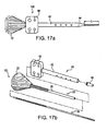
- FIG. 17 illustrates various views of a driver assembly comprising a rod, an inserter member, a threaded gauge and an end piece, according to the present invention.
- FIG. 18 illustrates various views of the inserter member of the driver assembly of FIG. 17 .
- FIG. 19 illustrates various views of the threaded gauge with thumb pad of the driver assembly of FIG. 17 .
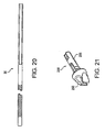
- FIG. 20 illustrates various views of the rod of the driver assembly of FIG. 17 .
- FIG. 21 illustrates various views of a swivel implant according to the present invention.
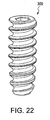
- FIG. 22 illustrates various views of a fixation device according to a first embodiment of the present invention and used in conjunction with the swivel implant of FIG. 20 and the driver of FIG. 17 .
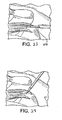
- FIGS. 23-28 depict a series of steps of shoulder repair using a plurality of swivel anchor devices according to the present invention.
- FIG. 29 illustrates various views of the driver assembly of the present invention.
- FIGS. 30 and 31 illustrate the swivel implant and traction suture.
- FIG. 32 is an enlarged view of the fixation device (cannulated screw) used in the present invention.
- FIG. 33 illustrates various views of a swivel anchor with a metal tip which avoids the need to pre-drill a hole in bone.
- FIGS. 34 and 35 provide additional illustrations of the swivel anchor assembly of the present invention, and the swivel anchor inserted in a bone socket, respectively.
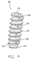
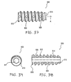
- FIGS. 36-39 illustrate various views of a fixation device with fenestrations and used in conjunction with the swivel anchor assembly.
- the present invention provides a fenestrated swivel suture anchor for knotless fixation of tissue.
- the swivel suture anchor is used with a suture chain formed of multiple loops of suture, preferably high strength suture.
- the loops of the chain are captured by mounting the swivel implant on a driver.
- the driver is also used to engage and lock the swivel implant in a hole in bone by inserting a cannulated fixation device (for example, an interference plug or screw) over the anchor.
- a cannulated fixation device for example, an interference plug or screw
- the present invention is used in a method for knotless fixation of anatomical tissue during surgical applications by employing a swivel suture anchor.
- the term “chain” is used in the specification and claims to refer to exemplary embodiments of the invention.
- a “chain” in this context refers broadly to a suture construct formed of a series of suture loops.
- the loops can be, but need not be, interlinked.
- the term “chain” as used in this application includes, but need not be limited to, the commonly understood definition in which links or rings are fitted into one another.
- the chains of the present invention can include two or more loops that are connected together. Each loop preferably has a fixed perimeter.
- the suture can be interlaced, rather than knotted, as described further below, to establish and maintain loop geometry.
- all loops are similar in size.
- FIGS. 1-16 illustrate two surgical procedures of approximating tissue (for example, a torn tendon) to bone according to exemplary embodiments of the present invention.
- tissue for example, a torn tendon
- FIGS. 1-16 illustrate two surgical procedures of approximating tissue (for example, a torn tendon) to bone according to exemplary embodiments of the present invention.
- the invention will be described below with reference to fixation of the rotator cuff; however, the invention is not limited to this exemplary embodiment and has applicability to fixation of tissue in general, such as, for example, fixation of torn tendons in ACL reconstructions of the knee or in fixation of any tendon to bone.
- FIGS. 1-16 Method steps of tissue fixation using the fenestrated suture anchor of the present invention are depicted schematically in FIGS. 1-16 .
- FIGS. 1-8 illustrate sequential steps during a rotator cuff repair using a knotless single row technique
- FIGS. 9-16 illustrate sequential steps during a rotator cuff repair using a knotless double row technique. Both techniques will be described with reference to driver assembly 100 ( FIGS. 17-20 ), swivel lock anchor 200 ( FIG. 21 ) and fixation device 300 ( FIG. 22 ).
- FIGS. 1-8 illustrate a series of subsequent steps in shoulder repair for a single-row repair technique using a swivel suture anchor according to the present invention.
- the mobility of the tear is assessed using a suture retriever/tissue grasper 105, such as the Arthrex KingFisher TM Suture Retriever/Tissue Grasper, as shown in FIG. 1 .
- a suture retriever/tissue grasper 105 such as the Arthrex KingFisher TM Suture Retriever/Tissue Grasper, as shown in FIG. 1 .
- margin convergence suturing may be required before approximation.
- a shaver, high-speed burr, or chondro pick is used to prepare a bleeding bone bed.
- the non-linked, free end 10a of a suture chain 10, such as the Arthrex FiberChain, is passed through the rotator cuff 150 using a suture passer 110, such as the Arthrex Scorpion TM Suture Passer, through a cannula, such as an Arthrex 5.75 mm Crystal Cannula.
- a suture passer 110 such as the Arthrex Scorpion TM Suture Passer
- a cannula such as an Arthrex 5.75 mm Crystal Cannula.
- the suture is retrieved through the same cannula.
- suture chain 10 is passed through the terminal link 10b at its opposite end, as shown in FIG. 3 .
- the loop 10b is cinched down by pulling on the free end 10a of the suture chain 10.
- the tip of the cannula may be used to help seat the suture chain loop securely against the rotator cuff 150.
- a suture retriever/tissue grasper 105 may be useful to ensure that the loop has been fully tightened.
- the second suture chain 11 is passed through the rotator cuff 150, the free end passed through the terminal loop, and the loop cinched in the same manner as for the first suture chain 10.
- the suture chain 10, 11 is used as a traction suture to determine the desired anchor location adjacent to the rotator cuff margin and a bone socket 155 is punched through a superolateral percutaneous portal with a punch 115, such as the Arthrex 5.5 mm Bio-Corkscrew FT Punch.
- a second bone socket 155 is also formed in the same manner for the second fiber chain 11.
- both suture chain ends 10a, 11a are retrieved through the lateral portal.
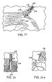
- the swivel implant 200 of the present invention is introduced through the percutaneous superolateral portal and captures the third link 10c from the free margin of the rotator cuff 150.
- the link 10c is captured by the forked anchor tip 250 of the anchor 200 (see FIG. 21 ).
- each link in the suture chain 10 is approximately 6 mm in length; therefore, since the total length of the swivel implant 200 is 18 mm, capturing the third link 10c from the cuff edge will usually position the cuff directly at the edge of the bone socket 155 and perfectly tension the suture chain 10 and the rotator cuff 150 segment that it spans, when the anchor tip 250 pushes the suture chain 10 to the bottom of the bone socket 155.
- the tissue tension is then evaluated, as shown in FIG. 6 .
- the driver assembly 100 is advanced into the bone socket 155 and the suture chain 10 is pushed toward the bottom of the socket 155 until the anchor body 225 contacts the bone. If the tension is not adequate, the driver 100 is removed from the bone socket 155 by pulling on the free end of the suture chain 10 (to release any wedging of the swivel-tip 250) at the same time that the driver assembly 100 is withdrawn. Then the adjacent, more proximal link is instead captured. If the tension is too great to fully insert the driver 100 to the bottom of the bone socket 155, the driver 100 is removed and the adjacent, more distal link is captured. Then the driver 100 is reinserted to the base of the bone socket. The forked tip 250 of the swivel implant 200 is held to the driver with a zero retention suture cleated at the driver's proximal end.
- Fixation device 300 such as a screw, is advanced by driver assembly 100 by holding the thumb pad 50 as the inserter handle 22 is turned clockwise, as shown in FIG. 7 .
- the shaft 225 of the swivel implant 200 is fully engaged by the fixation device 300 to optimize the stability of the swivel implant construct 400.
- the swivel anchor construct 400 comprises swivel implant 200 and fixation device 300.
- the tip retention suture is unwound from the cleat at the back of the driver handle 22 and the driver assembly 100 is removed. Then, one limb of the retention suture is pulled to fully remove it from the implant.
- the insertion steps are repeated for the second swivel anchor construct 400 to obtain the final suture/anchor construct, shown in FIG. 8 .
- the free suture ends 10a, 11a are cut with a suture cutter, such as the Arthrex open ended FiberWire Suture Cutter, so that they are flush with the edge of the bone socket 155.
- FIGS. 9-16 illustrate a series of subsequent steps in shoulder repair for a double-row repair technique using a swivel suture anchor according to the present invention.
- suture retriever/tissue grasper In the case of a large U-shaped tear, margin convergence suturing may be required before approximation of the tendon.
- a shaver, high-speed burr, or chondro pick is used to prepare a bleeding bone bed.
- pilot holes 160 are prepared for two suture anchors 120, such as Arthrex Bio-Corkscrew FT suture anchors, that will comprise the medial row through a percutaneous superolateral portal.
- a punch 115 such as the Arthrex 5.5 mm Bio-Corkscrew FT Punch, is advanced to the laser line at a 45° "deadman" angle, adjacent to the articular margin of the humerus to form the pilot holes 160. Tapping is seldom, but may be, necessary.
- both suture anchors 120 are placed.
- the suture anchors 120 come preloaded with suture chain 10.
- the suture leader is retrieved from one of the suture chain 10 strands through the lateral portal and is loaded onto a suture passer 110, such as the Arthrex Scorpion Suture Passer.
- the suture chain 10 is passed through the rotator cuff 150 approximately 15 mm from the free margin of the rotator cuff 150. This step is then repeated for the second suture chain 11.
- both suture chain suture ends 10a, 11a are retrieved through the lateral portal and are tensioned to bring the cuff into contact with the medial portion of the footprint.
- the tip of the cannula may be used to push the tendon against the footprint.
- two bone sockets 155 are formed for the lateral row swivel implants 200 using a punch 115. These two bone sockets 155 should be adjacent to the lateral margin of the cuff 150 when the cuff 150 is appropriately tensioned by the two previously placed suture chains 10, 11.
- the swivel implant 200 is introduced through the percutaneous superolateral portal, capturing the third link 10c from the free margin of the rotator cuff 150.
- the link 10c is captured by the forked anchor tip 250 of the swivel implant 200 (see FIG. 21 ).
- each link in the suture chain 10, 11 is approximately 6 mm in length; therefore, since the total length of the swivel implant 200 is 18 mm, capturing the third link from the cuff edge will usually position the cuff directly at the edge of the bone socket 155 and perfectly tension the suture chain 10 and the rotator cuff segment that it spans when the anchor tip 250 pushes the suture chain 10 to the bottom of the bone socket 155.
- the tissue tension is then evaluated, as shown in FIG. 14 .
- the driver assembly 100 is advanced into the bone socket 155 and the suture chain 10 is pushed toward the bottom of the socket 155 until the anchor body 225 contacts the bone. If the tension is not adequate, the driver is removed from the bone socket by pulling on the free end of the suture chain 10 (to release any wedging of the swivel-tip 250) at the same time that the driver assembly 100 is withdrawn and the adjacent, more proximal link is instead captured. If the tension is too great to fully insert the driver to the bottom of the bone socket 155, the driver assembly 100 is removed and the adjacent, more distal link is instead captured. Then the driver 100 is reinserted to the base of the bone socket 155.
- Fixation device 300 e.g., a screw
- Fixation device 300 is advanced by holding the thumb pad 50 as the inserter handle 22 is turned clockwise, as shown in FIG. 15 .
- the shaft 225 of the swivel implant 200 is fully engaged by the body of the fixation device 300 to optimize the stability of the swivel implant construct 400.
- the swivel anchor construct 400 comprises anchor 200 and fixation device 300.
- the tip retention suture is unwound from the cleat at the back of the driver handle 200 and the driver 100 is removed. One limb of the retention suture is pulled to fully remove it from the implant.
- FIGS. 13-15 The steps of FIGS. 13-15 are then repeated for the second swivel implant construct 400 to obtain the final construct, shown in FIG. 16 .
- the free suture ends are cut with a suture cutter so that they are flush with the edge of the bone socket 155.
- the invention may also be used for a side-to-side closure of soft tissue using a suture chain 10.
- This method includes using the suture chain 10 to perform the side-to-side closure of the soft tissue with a final step of anchoring a chain link at the lateral aspect of the repair to bone using an anchor, such as anchor 200.
- the anchoring step is the same as that illustrated in the first two embodiments.
- a suture anchor similar to suture anchor 120, may be inserted into bone at the medial aspect of the repair, a side-by-side margin convergence is implemented using the suture chain in a "shoelace-type" stitch, and the suture chain is anchored at the lateral aspect of the repair to bone using an anchor, such as anchor 200.
- driver assembly 100 comprises a cannulated driver 20 including shaft 25 and inserter handle 22; tube or rod 30 that passes slidably and rotatably through the cannulated driver 20; threaded gauge 40 including a cannulated body 42 and thumb pad 50; and tip 44.
- FIG. 17 illustrates the driver assembly 100 both in assembled (A) and unassembled (B) form.
- FIG. 18 provides a more detailed view of the cannulated driver 20 of the driver assembly 100.
- FIG. 19 provides a more detailed view of the threaded gauge 40 of the driver assembly 100.
- FIG. 20 provides a more detailed view of the rod 30 of the driver assembly 100.
- FIG. 21 illustrates various views of swivel implant 200.
- the implant body 225 is assembled onto the operational end of the driver 100.
- the implant tip 250 is threaded or otherwise attached onto the tip of thin rod or tube 30.
- forked tip 250 is used to capture a suture chain 10, 11 (that has been laced through a shoulder ligament, as shown in the two exemplary embodiments above) for installation into a pre-drilled hole 155 in bone.
- the implant 200 has a threaded body 225 and a detachable forked tip 250.
- the forked tip 250 may be rotatably attached to the implant body 225. This enables rotational insertion of the implant 200 without causing excessive twisting and knotting of the suture chain 10, 11 by the forked tip 250.
- FIG. 22 illustrates various views of a fixation device 300 (for example, a cannulated interference screw) that is employed in conjunction with the driver assembly 100 and the swivel implant 200.
- the fixation device 300 is preloaded on the driver assembly 100.
- the fixation device 300 is advanced into the bone socket 155 by holding the thumb pad 50 as the inserter handle 22 is turned clockwise.
- the shaft 225 of the forked swivel implant 200 is fully engaged by the fixation device 300 to optimize the stability of the swivel implant construct 400.
- the swivel implant construct 400 is composed of anchor 200 and fixation device 300.
- suture anchor 400 is includes a threaded fixation device.
- suture anchor 400 may also include a ribbed (push-in) fixation member such as an Arthrex Push-LockTM- anchor, but including a forked tip in order to capture a given link of the suture chain.
- the suture chain 10, 11 passed through the tissue can be secured either using a single anchor or a plurality of anchors.
- various anchors, such as those noted above and others may be used interchangeably with only slight variations in the above procedure.
- the suture chain 10, 11 can be secured by capturing two of the chain loops in forked tines prior to insertion of the anchor or anchors.
- regular suture may be used in addition to the suture chains of the present invention.
- the first suture anchor 120 of the double row embodiment will be pre-loaded with regular suture (for example, the Arthrex BioCorkscrewTM or Arthrex BioCorkscrew-FTTM, disclosed in U.S. Application Publication No. 2007/0060922 ).
- regular suture for example, the Arthrex BioCorkscrewTM or Arthrex BioCorkscrew-FTTM, disclosed in U.S. Application Publication No. 2007/0060922 .
- the technique is similar to the one described above, except that the lateral fixation is accomplished by capturing the suture limbs (rather than chain-links) in the fork of the implant 200 and tensioning the suture as the implant 200 is placed. This relies on interference fixation of the suture between the implant 200 and the bone.
- the swivel anchor and suture chain assembly of the present invention has application in surgical tissue repair, for example, in conjunction with one or more bone anchors.
- Tension on repair constructs is adjustable through selection of the chain link or links to be snagged by a bone anchor.
- FIGS. 23-35 describe another embodiment.
- FIG. 23 illustrates a side view of a human shoulder of a patient undergoing a rotator cuff repair in accordance with an exemplary embodiment of the present invention.
- the patient may be positioned in the beach chair position using the Arthrex Beach Chair Lateral Traction Device or in a lateral decubitus position using the Arthrex 3-Point Shoulder Distraction System. Access to the subacromial space is facilitated with a variety of cannulas.
- the mobility of the tear is assessed using, for example, a tissue grasper 610 such as the Arthrex KingFisherTM Suture Retriever/Tissue Grasper, to determine whether a U or L-shaped component exists.
- tissue grasper 610 such as the Arthrex KingFisherTM Suture Retriever/Tissue Grasper
- margin convergence suturing is performed to reduce volume and strain on the repair.
- the length and width of the rotator cuff footprint is assessed and a bleeding bed for enhanced tendon to bone healing may be formed. This may be accomplished with a burr to perform a light dusting of the greater tuberosity, or by using a chondro pick to microfracture the footprint and maximize vascular channels.
- FIG. 24 illustrates the preparation of two pilot holes for two swivel anchors that will be inserted in the medial row.
- a punch may be employed adjacent to the articular margin of the humerus and at about 45° angle to form the two pilot holes.
- a swivel implant 630 loaded with a strand of suture tape 640, preferably Arthrex FiberTape, is placed in the medial pre-formed hole 632.
- the anchor of the present invention can be used with any type of flexible material or suture.
- the driver is then rotated to advance screw 642 down shaft 620 to secure the implant and suture in the bone hole. More specifically, as shown in FIG. 26a , the screw 642 is advanced by holding thumb pad 650 as the driver handle 622 is turned clockwise.
- An Arthrex FiberLink and an Arthrex Scorpion suture passer 644 are used to shuttle both tails of the suture tape through the rotator cuff 634 simultaneously. This procedure is followed for both medial swivel anchors.
- one tail of suture tape 640 from each medial swivel anchor is retrieved and loaded through the eyelet of another swivel implant 630, and that implant is installed in then inserted into a preformed lateral bone socket.
- the tension of the suture tape 640 is adjusted if necessary.
- the swivel anchor driver is then rotated in clockwise direction as before to advance the screw 642 over the implant to complete insertion. This step is repeated in another lateral bone socket with the other tails of suture tape from each medial anchor.
- the tails of the suture tape 640 are then cut, one at a time, to complete the construct as shown in FIG. 28 .
- FIGS. 34 and 35 provide additional illustrations of the swivel anchor assembly and the anchor inserted in a bone socket, respectively.
- a driver 668 is used to install the knotless fixation devices with a swiveling implant.
- Driver 668 features a thin cannulated rod 620 passing slidably and rotatably through a cannulated driver assembly.
- the tip of thin cannulated rod 620 is adapted to accept swivel anchor implant 642 within the cannulation at its tip, preferably via a snap fit.
- Cannulated rod 620 has a hexagonal outer surface for receiving anchor body (preferably a screw) 642 having a corresponding cannulation.
- FIG. 32 illustrates a detailed view of the cannulated screw 642.
- FIG. 29(c) illustrates the swivel anchor implant 630.
- traction sutures 671 extending from the proximal end of the swivel anchor implant 630 are threaded through the cannulation of the driver 668 (see also FIG. 29(c) ).
- traction sutures 671 prevent inadvertent separation of the implant 630 from the driver during insertion, but they can be used subsequently for additional tie-down of the tendon after the driver is removed. Subsequently, the swivel anchor implant 630 is seated on the driver tip and until advanced until it snaps onto place ( FIG. 29(d) ). A protective tube 694 ( FIG. 29(e) ) may be placed over the tip of the assembly for shipping purposes. The traction sutures 671 may be looped around the driver handle, as shown in FIGS. 29(f) and (g) , and secured in a cleat 698 to prevent the implant 630 from becoming prematurely detached from the driver.
- the knotless fixation device of the present invention advantageously minimizes or eliminates the need to tie knots.
- the use of such a swivel anchor also provides secure fixation of the suture construct - the secure suture construct results from the suture being pushed into a hole and held tightly by an anchors.
- suture tape is used with the swivel anchor to fix tissue to bone.
- the swivel anchor of the present invention can be used with any type of flexible material or suture.
- an allograft or biological component may be used instead of suture or tape.
- the allograft or biological component may be comprised of tendon or pericardium, for example, which provides improved tissue repair.
- any combination of suture, suture tape, and allograft or biological component may be employed, depending on the characteristics of the specific surgical repair and/or as desired.
- FIG. 33 illustrate a swivel implant 540 which is provided with a pointed metal tip to facilitate insertion of the implant without the need to pre-drill or pre-form a hole in the bone.
- the conical configuration of the most distal end pointed tip 550 allows the implant to undergo a self-punching operation, eliminating any need to pre-drill a hole in the bone.
- the conical configuration of the most distal end of the pointed tip implant 550 also provides suture fixation strength, as well as accelerated graft/tendon healing to bone.
- the pointed tip implant 550 may be detachable from the driver.
- pointed tip implant 540 is provided with a metal tip 550 and an eyelet or aperture 555 for receiving suture or suture tape.
- Pointed tip implant 550 is also provided, at its most distal end, with a conical portion 551 which allows direct advancement of the implant (by simply tapping the device with a mallet, for example) without the formation of a pilot hole in bone.
- the conical portion 551 of the implant is formed of titanium or titanium alloy.
- eyelet or aperture 555 is also formed of titanium or similar material, to withstand impaction forces during the graft fixation procedure.
- FIGS. 36-39 illustrate various views of another exemplary fixation device 500 of the present invention that is employed in conjunction with the driver assembly 100 and the swivel implant 200 and 540.
- the fixation device 500 is similar to the fixation device 300 of FIG. 22 , but differs from it in that the fixation device 500 is provided with a plurality of openings or fenestrations 505 provided on the outer surface of the body of the device.
- the openings or fenestrations 505 may have various dimensions and geometries provide multiple pathways for w blood to pass through the device (i.e, through the fenestrations and up through the cannulation) and, therefore, to the repair site to promote healing.
- the fenestrations also promote in-growth of bone.
- the decreased mass of the device 500 (resulting from the fenestrations) further promotes healing and in-growth.
- the fixation device 500 is preloaded on the driver assembly 100.
- the fixation device 500 is advanced into the bone socket 155 by holding the thumb pad 50 as the inserter handle 22 is turned clockwise.
- the shaft 225 of the forked swivel implant 200 is fully engaged by the fixation device 500 to optimize the stability of the swivel anchor construct (composed of implant 200 and fixation device 500).
- the fixation device 500 includes a cannulated body 512 in the form of a tapered cylinder having a proximal end 513 and a distal end 515.
- a continuous thread 520 wraps around cannulated body 512 in a clockwise direction, as shown.
- the distal end 515 of the interference screw 500 terminates in an exposed, flat surface provided with an opening 516.
- the proximal end 513 of the interference screw 500 terminates in a drive socket 517 that allows a driver to seat snuggly in the drive socket to allow manipulation and installation of the interference screw into the bone socket, while fully engaging the shaft of the swivel implant 200 (as detailed above with reference to interference crew 300).
- the proximal end 513 of the fixation device 500 terminates in a drive socket 517 that allows a driver to seat snuggly in the drive socket to allow manipulation and installation of the interference screw into the bone socket, while fully engaging the shaft of the swivel anchor 630 or swivel implant 540 (as detailed above with reference to interference screw 642).
- drive socket 517 may be configured to be used with a traditional hex drive screwdriver.
- the drive socket 517 has been described as having hexagonal shape, the drive socket may also have a Delta drive configuration or a cruciform shape, among others, that allows the driver to rotationally engage the interference screw, to turn simultaneously with the driver.
- the fixation device 500 of the present invention may be formed of a biocompatible and/or biosorbable material.
- screw 500 is formed of a bioabsorbable material, such as poly-(L-lactic acid) (PLLA), poly-(D,L-lactide), and poly glycolic acid (PGA), for example, or other bioabsorbable, non-metallic materials, which may be especially tailored for hardness, tensile strength and compressive strength.
- fixation device 500 may be formed of titanium, titanium alloy, stainless steel or stainless steel alloy.
- Other biocompatible materials which could be used include plastics, allograft bone and inert bone substitute materials.
- a growth material may be advanced through the cannulated driver and into the screw 500 by employing a plunger, for example. As the driver is pulled out, the plunger pushes the flow material through the cannulation of the driver and into the body of the screw 500. The growth material will subsequently harden to allow better fixation of the interference screw 500 against the bone and the shaft of the swivel implant 200 and 540.
- the growth material may be any solid, semi-solid, viscous, flowable, gel or elastic composition or mixture that allows its easy manipulation and insertion into the body 512 of the interference screw 500.
- the growth material may contain growth factors such as autogenous growth factors, for example platelet-rich plasma (PRP), optionally in combination with hyaluronic acid (HY acid) and/or with a coagulant such as thrombin.
- PRP platelet-rich plasma
- HY acid hyaluronic acid
- a coagulant such as thrombin.
- growth factor as used in the present application is intended to include all factors, such as proteinaceous factors, for example, which play a role in the induction or conduction of growth of bone, ligaments, cartilage or other tissues associated with bone or joints.
- these growth factors include bFGF, aFGF, EGF (epidermal growth factor), PDGF (platelet-derived growth factor), IGF (insulin-like growth factor), TGF- ⁇ . I through III, including the TGF- ⁇ . superfamily (BMP-1 through 12, GDF 1 through 12, dpp, 60A, BIP, OF).
- the growth material may comprise additional osteoconductive bone adhesives, calcium carbonate, fatty acids, lubricants, antiseptic chemicals and/or antibiotics.
- additional solution excipients such as buffer salts, sugars, anti-oxidants and preservatives to maintain the bioactivity of the growth material and a proper pH of the growth material may be also employed.
- the additional lubricants and/or the antiseptic and/or the antibiotic will typically be present in the growth material in a predetermined concentration range, which will be dependent upon the particular bone site and application, as well as the specific activity of the antiseptic and/or the antibiotic.
Landscapes
- Health & Medical Sciences (AREA)
- Life Sciences & Earth Sciences (AREA)
- Animal Behavior & Ethology (AREA)
- General Health & Medical Sciences (AREA)
- Veterinary Medicine (AREA)
- Engineering & Computer Science (AREA)
- Biomedical Technology (AREA)
- Heart & Thoracic Surgery (AREA)
- Public Health (AREA)
- Rheumatology (AREA)
- Surgery (AREA)
- Orthopedic Medicine & Surgery (AREA)
- Rehabilitation Therapy (AREA)
- Cardiology (AREA)
- Oral & Maxillofacial Surgery (AREA)
- Transplantation (AREA)
- Vascular Medicine (AREA)
- Molecular Biology (AREA)
- Medical Informatics (AREA)
- Nuclear Medicine, Radiotherapy & Molecular Imaging (AREA)
- Surgical Instruments (AREA)
- Prostheses (AREA)
Abstract
A fenestrated suture anchor for fixation of tissue to bone comprises an implant (200), such a swivel implant (200) with a forked tip (250) for capturing a suture. The implant can be secured in a hole in bone by advancing a fixation device (500), such as a cannulated interference screw (500), to engage and fully seat the implant. The cannulated fixation device (500) is provided with a plurality of openings (505) or fenestrations (505) of various dimensions and geometries to provide multiple pathways through the anchor (i.e., though the interior of the body and through the fenestrations) to allow blood to flow to increase the healing zone, for example, for rotator cuff repair, while also promoting bone in-growth.

Description
- The present invention relates to surgical fixation and, more particularly, to methods of conducting anatomical tissue repair, such as ligament repair and reconstruction, using a fenestrated suture anchor.
- When soft tissue tears away from bone, reattachment becomes necessary. Various devices, including sutures, screws, staples, wedges, anchors and plugs have been used in the prior art to secure soft tissue to bone. Surgical methods utilizing suture anchors alone are disadvantageous for reattachment of large areas of detached tissue because they often do not allow good tissue to bone contact.
- Reattachment of soft tissue to bone typically requires the surgeon to pass suture material through selected tissue, form a plurality of surgical knots extracorporeally and then move the knots into position adjacent the desired tissue to be sutured. In such procedures, the surgeon must manually tie the knots on the suture strands after the suture is threaded through the selected tissues to be sutured. Knot tying during surgery, particularly arthroscopic surgery, is tedious and time-consuming. There is also a tendency for the knots to deform or collapse as the surgeon manually forces the knots down into the proper position. Also, the suture knots often are exposed to abrasion or cutting by sharp or rough areas along the walls of the bone canal into which anchors are typically inserted to provide fixation of tendon to bone.
- Accordingly, a need exists for an improved suture anchor for attaching soft tissue to bone which does not require multiple suture knots and which allows the tendon to remain securely in place until the ligaments naturally attach to bone. A need also exists for such a knotless suture anchor for attaching tissue to bone which employs an implant with a fenestrated configuration that promotes healing of tissue.
- The present invention is a fenestrated swivel suture anchor for knotless tissue fixation for anatomical tissue repair and reconstruction. In one embodiment, the swivel swivel suture anchor is used to capture a suture chain formed of at least two loops formed of high strength suture. A driver is provided direct the tip of the swivel implant to capture loops of the suture chain. The swivel implant is locked and secured in bone by inserting a cannulated fixation device (for example, an interference plug or screw) over the implant. The cannulated fixation device is provided with a plurality of openings or fenestrations of various dimensions and geometries to provide multiple pathways through the device (i.e., though the interior of the body and through the fenestrations) to allow blood to flow to increase the healing zone, for example, for rotator cuff repair, while also promoting bone in-growth.
- The present invention overcomes the disadvantages of the prior art, such as those noted above, by providing a swivel implant at the distal end of a driver that securely engages and locks into a cannulated ribbed body of an interference plug or screw. The swivel implant includes a closed aperture for receiving a strand attached to a graft, such that the strand is able to freely slide through the aperture.
- In one embodiment of the invention, the strand is passed through the graft at desired points. A cannulated plug or screw is pre-loaded onto a driver provided with a swivel lock twist-in anchor at its distal end. The strand attached to the graft is passed through the aperture of the swivel implant located at the distal end of the driver. The distal end of the driver together with the implant is inserted directly into the bone. The driver may be rotated (in a clockwise direction, for example) to advance a screw over the anchor to complete insertion. The cannulated plug or screw is provided with a plurality of openings or fenestrations of various dimensions and geometries to provide multiple pathways through the device (i.e., though the interior of the body and through the fenestrations) to allow blood to flow to increase the healing zone, for example, for rotator cuff repair, while also promoting bone in-growth
- Other features and advantages of the present invention will become apparent from the following description of exemplary embodiments of the invention described with reference to the accompanying drawings.
-
FIGS. 1-8 depict a series of subsequent steps of shoulder repair using a single-row technique with a swivel suture anchor according to the present invention. -
FIGS. 9-16 depict a series of subsequent steps of shoulder repair using a double-row technique with a swivel suture anchor according to the present invention. -
FIG. 17 illustrates various views of a driver assembly comprising a rod, an inserter member, a threaded gauge and an end piece, according to the present invention. -
FIG. 18 illustrates various views of the inserter member of the driver assembly ofFIG. 17 . -
FIG. 19 . illustrates various views of the threaded gauge with thumb pad of the driver assembly ofFIG. 17 . -
FIG. 20 illustrates various views of the rod of the driver assembly ofFIG. 17 . -
FIG. 21 illustrates various views of a swivel implant according to the present invention. -
FIG. 22 illustrates various views of a fixation device according to a first embodiment of the present invention and used in conjunction with the swivel implant ofFIG. 20 and the driver ofFIG. 17 . -
FIGS. 23-28 depict a series of steps of shoulder repair using a plurality of swivel anchor devices according to the present invention. -
FIG. 29 illustrates various views of the driver assembly of the present invention. -
FIGS. 30 and 31 illustrate the swivel implant and traction suture. -
FIG. 32 is an enlarged view of the fixation device (cannulated screw) used in the present invention. -
FIG. 33 illustrates various views of a swivel anchor with a metal tip which avoids the need to pre-drill a hole in bone. -
FIGS. 34 and35 provide additional illustrations of the swivel anchor assembly of the present invention, and the swivel anchor inserted in a bone socket, respectively. -
FIGS. 36-39 illustrate various views of a fixation device with fenestrations and used in conjunction with the swivel anchor assembly. - The present invention provides a fenestrated swivel suture anchor for knotless fixation of tissue. In one embodiment, the swivel suture anchor is used with a suture chain formed of multiple loops of suture, preferably high strength suture. The loops of the chain are captured by mounting the swivel implant on a driver. The driver is also used to engage and lock the swivel implant in a hole in bone by inserting a cannulated fixation device (for example, an interference plug or screw) over the anchor.
- The present invention is used in a method for knotless fixation of anatomical tissue during surgical applications by employing a swivel suture anchor. The term "chain" is used in the specification and claims to refer to exemplary embodiments of the invention. A "chain" in this context refers broadly to a suture construct formed of a series of suture loops. The loops can be, but need not be, interlinked. In this manner, the term "chain" as used in this application includes, but need not be limited to, the commonly understood definition in which links or rings are fitted into one another. Rather, the chains of the present invention can include two or more loops that are connected together. Each loop preferably has a fixed perimeter. The suture can be interlaced, rather than knotted, as described further below, to establish and maintain loop geometry. Preferably, all loops are similar in size.
- Referring now to the drawings, where like elements are designated by like reference numerals,
FIGS. 1-16 illustrate two surgical procedures of approximating tissue (for example, a torn tendon) to bone according to exemplary embodiments of the present invention. For simplicity, the invention will be described below with reference to fixation of the rotator cuff; however, the invention is not limited to this exemplary embodiment and has applicability to fixation of tissue in general, such as, for example, fixation of torn tendons in ACL reconstructions of the knee or in fixation of any tendon to bone. - Method steps of tissue fixation using the fenestrated suture anchor of the present invention are depicted schematically in
FIGS. 1-16 . As described in more detail below,FIGS. 1-8 illustrate sequential steps during a rotator cuff repair using a knotless single row technique andFIGS. 9-16 illustrate sequential steps during a rotator cuff repair using a knotless double row technique. Both techniques will be described with reference to driver assembly 100 (FIGS. 17-20 ), swivel lock anchor 200 (FIG. 21 ) and fixation device 300 (FIG. 22 ). - Although the single and double row techniques are described below with reference to specific instruments sold by Arthrex, Inc., the assignee of the present application, and with reference to a series of specific steps and devices used during the surgical tissue fixation, it should be understood that the invention is not limited to the specific disclosure of these embodiments and contemplates modifications and variations that are apparent to those skilled in the art. Accordingly, the invention must not be limited to the specific embodiments detailed below, as they are only exemplary in nature.
-
FIGS. 1-8 illustrate a series of subsequent steps in shoulder repair for a single-row repair technique using a swivel suture anchor according to the present invention. - The mobility of the tear is assessed using a suture retriever/
tissue grasper 105, such as the Arthrex KingFisher™ Suture Retriever/Tissue Grasper, as shown inFIG. 1 . In the case of a large U-shaped tear, margin convergence suturing may be required before approximation. Then, a shaver, high-speed burr, or chondro pick is used to prepare a bleeding bone bed. - As shown in
FIG. 2 , the non-linked,free end 10a of asuture chain 10, such as the Arthrex FiberChain, is passed through therotator cuff 150 using asuture passer 110, such as the Arthrex Scorpion™ Suture Passer, through a cannula, such as an Arthrex 5.75 mm Crystal Cannula. Next, the suture is retrieved through the same cannula. - Then the
free end 10a ofsuture chain 10 is passed through theterminal link 10b at its opposite end, as shown inFIG. 3 . Theloop 10b is cinched down by pulling on thefree end 10a of thesuture chain 10. The tip of the cannula may be used to help seat the suture chain loop securely against therotator cuff 150. A suture retriever/tissue grasper 105 may be useful to ensure that the loop has been fully tightened. Thesecond suture chain 11 is passed through therotator cuff 150, the free end passed through the terminal loop, and the loop cinched in the same manner as for thefirst suture chain 10. - As shown in
FIG. 4 , thesuture chain bone socket 155 is punched through a superolateral percutaneous portal with apunch 115, such as the Arthrex 5.5 mm Bio-Corkscrew FT Punch. Asecond bone socket 155 is also formed in the same manner for thesecond fiber chain 11. - As shown in
FIG. 5 , both suture chain ends 10a, 11a are retrieved through the lateral portal. Theswivel implant 200 of the present invention is introduced through the percutaneous superolateral portal and captures the third link 10c from the free margin of therotator cuff 150. The link 10c is captured by the forkedanchor tip 250 of the anchor 200 (seeFIG. 21 ). In a preferred embodiment, each link in thesuture chain 10 is approximately 6 mm in length; therefore, since the total length of theswivel implant 200 is 18 mm, capturing the third link 10c from the cuff edge will usually position the cuff directly at the edge of thebone socket 155 and perfectly tension thesuture chain 10 and therotator cuff 150 segment that it spans, when theanchor tip 250 pushes thesuture chain 10 to the bottom of thebone socket 155. - The tissue tension is then evaluated, as shown in
FIG. 6 . Thedriver assembly 100 is advanced into thebone socket 155 and thesuture chain 10 is pushed toward the bottom of thesocket 155 until theanchor body 225 contacts the bone. If the tension is not adequate, thedriver 100 is removed from thebone socket 155 by pulling on the free end of the suture chain 10 (to release any wedging of the swivel-tip 250) at the same time that thedriver assembly 100 is withdrawn. Then the adjacent, more proximal link is instead captured. If the tension is too great to fully insert thedriver 100 to the bottom of thebone socket 155, thedriver 100 is removed and the adjacent, more distal link is captured. Then thedriver 100 is reinserted to the base of the bone socket. The forkedtip 250 of theswivel implant 200 is held to the driver with a zero retention suture cleated at the driver's proximal end. -
Fixation device 300, such as a screw, is advanced bydriver assembly 100 by holding thethumb pad 50 as theinserter handle 22 is turned clockwise, as shown inFIG. 7 . When the swivel anchor construct 400 is fully seated, theshaft 225 of theswivel implant 200 is fully engaged by thefixation device 300 to optimize the stability of theswivel implant construct 400. The swivel anchor construct 400 comprisesswivel implant 200 andfixation device 300. The tip retention suture is unwound from the cleat at the back of thedriver handle 22 and thedriver assembly 100 is removed. Then, one limb of the retention suture is pulled to fully remove it from the implant. - The insertion steps are repeated for the second swivel anchor construct 400 to obtain the final suture/anchor construct, shown in
FIG. 8 . The free suture ends 10a, 11a are cut with a suture cutter, such as the Arthrex open ended FiberWire Suture Cutter, so that they are flush with the edge of thebone socket 155. -
FIGS. 9-16 illustrate a series of subsequent steps in shoulder repair for a double-row repair technique using a swivel suture anchor according to the present invention. - The mobility of the tear is assessed using suture retriever/tissue grasper. In the case of a large U-shaped tear, margin convergence suturing may be required before approximation of the tendon. A shaver, high-speed burr, or chondro pick is used to prepare a bleeding bone bed. Then, as shown in
FIG. 9 ,pilot holes 160 are prepared for two suture anchors 120, such as Arthrex Bio-Corkscrew FT suture anchors, that will comprise the medial row through a percutaneous superolateral portal. Apunch 115, such as the Arthrex 5.5 mm Bio-Corkscrew FT Punch, is advanced to the laser line at a 45° "deadman" angle, adjacent to the articular margin of the humerus to form the pilot holes 160. Tapping is seldom, but may be, necessary. - As shown in
FIG. 10 , both suture anchors 120 are placed. In a preferred embodiment, the suture anchors 120 come preloaded withsuture chain 10. - Then, as shown in
FIG. 11 , the suture leader is retrieved from one of thesuture chain 10 strands through the lateral portal and is loaded onto asuture passer 110, such as the Arthrex Scorpion Suture Passer. Thesuture chain 10 is passed through therotator cuff 150 approximately 15 mm from the free margin of therotator cuff 150. This step is then repeated for thesecond suture chain 11. - As shown in
FIG. 12 , both suture chain suture ends 10a, 11a are retrieved through the lateral portal and are tensioned to bring the cuff into contact with the medial portion of the footprint. The tip of the cannula may be used to push the tendon against the footprint. Then twobone sockets 155 are formed for the lateralrow swivel implants 200 using apunch 115. These twobone sockets 155 should be adjacent to the lateral margin of thecuff 150 when thecuff 150 is appropriately tensioned by the two previously placedsuture chains - As shown in
FIG. 13 , theswivel implant 200 is introduced through the percutaneous superolateral portal, capturing the third link 10c from the free margin of therotator cuff 150. The link 10c is captured by the forkedanchor tip 250 of the swivel implant 200 (seeFIG. 21 ). In a preferred embodiment, each link in thesuture chain swivel implant 200 is 18 mm, capturing the third link from the cuff edge will usually position the cuff directly at the edge of thebone socket 155 and perfectly tension thesuture chain 10 and the rotator cuff segment that it spans when theanchor tip 250 pushes thesuture chain 10 to the bottom of thebone socket 155. - The tissue tension is then evaluated, as shown in
FIG. 14 . Thedriver assembly 100 is advanced into thebone socket 155 and thesuture chain 10 is pushed toward the bottom of thesocket 155 until theanchor body 225 contacts the bone. If the tension is not adequate, the driver is removed from the bone socket by pulling on the free end of the suture chain 10 (to release any wedging of the swivel-tip 250) at the same time that thedriver assembly 100 is withdrawn and the adjacent, more proximal link is instead captured. If the tension is too great to fully insert the driver to the bottom of thebone socket 155, thedriver assembly 100 is removed and the adjacent, more distal link is instead captured. Then thedriver 100 is reinserted to the base of thebone socket 155. -
Fixation device 300, e.g., a screw, is advanced by holding thethumb pad 50 as theinserter handle 22 is turned clockwise, as shown inFIG. 15 . When theswivel anchor 400 is fully seated, theshaft 225 of theswivel implant 200 is fully engaged by the body of thefixation device 300 to optimize the stability of theswivel implant construct 400. As previously stated, the swivel anchor construct 400 comprisesanchor 200 andfixation device 300. The tip retention suture is unwound from the cleat at the back of thedriver handle 200 and thedriver 100 is removed. One limb of the retention suture is pulled to fully remove it from the implant. - The steps of
FIGS. 13-15 are then repeated for the second swivel implant construct 400 to obtain the final construct, shown inFIG. 16 . The free suture ends are cut with a suture cutter so that they are flush with the edge of thebone socket 155. - In addition to the above exemplary embodiments, the invention may also be used for a side-to-side closure of soft tissue using a
suture chain 10. This method includes using thesuture chain 10 to perform the side-to-side closure of the soft tissue with a final step of anchoring a chain link at the lateral aspect of the repair to bone using an anchor, such asanchor 200. The anchoring step is the same as that illustrated in the first two embodiments. Furthermore, if the soft tissue split to be repaired overlies bone for its entire length, a suture anchor, similar tosuture anchor 120, may be inserted into bone at the medial aspect of the repair, a side-by-side margin convergence is implemented using the suture chain in a "shoelace-type" stitch, and the suture chain is anchored at the lateral aspect of the repair to bone using an anchor, such asanchor 200. - Reference is now made to
FIGS. 17-22 , which illustrate details of the driver assembly 100 (FIGS. 17-20 ), the swivel implant 200 (FIG. 21 ) and the fixation device 300 (FIG. 22 ). As illustrated inFIGS. 17-20 ,driver assembly 100 comprises a cannulateddriver 20 includingshaft 25 and inserter handle 22; tube orrod 30 that passes slidably and rotatably through the cannulateddriver 20; threadedgauge 40 including a cannulatedbody 42 andthumb pad 50; andtip 44.FIG. 17 illustrates thedriver assembly 100 both in assembled (A) and unassembled (B) form.FIG. 18 provides a more detailed view of the cannulateddriver 20 of thedriver assembly 100.FIG. 19 provides a more detailed view of the threadedgauge 40 of thedriver assembly 100.FIG. 20 provides a more detailed view of therod 30 of thedriver assembly 100. -
FIG. 21 illustrates various views ofswivel implant 200. During installation ofswivel implant 200, theimplant body 225 is assembled onto the operational end of thedriver 100. Theimplant tip 250 is threaded or otherwise attached onto the tip of thin rod ortube 30. As detailed above, forkedtip 250 is used to capture asuture chain 10, 11 (that has been laced through a shoulder ligament, as shown in the two exemplary embodiments above) for installation into apre-drilled hole 155 in bone. Theimplant 200 has a threadedbody 225 and a detachable forkedtip 250. The forkedtip 250 may be rotatably attached to theimplant body 225. This enables rotational insertion of theimplant 200 without causing excessive twisting and knotting of thesuture chain tip 250. -
FIG. 22 illustrates various views of a fixation device 300 (for example, a cannulated interference screw) that is employed in conjunction with thedriver assembly 100 and theswivel implant 200. Preferably, thefixation device 300 is preloaded on thedriver assembly 100. As described above with reference to the two exemplary embodiments, thefixation device 300 is advanced into thebone socket 155 by holding thethumb pad 50 as theinserter handle 22 is turned clockwise. When thefixation device 300 is fully seated, theshaft 225 of the forkedswivel implant 200 is fully engaged by thefixation device 300 to optimize the stability of theswivel implant construct 400. As previously stated, the swivel implant construct 400 is composed ofanchor 200 andfixation device 300. - In the two exemplary embodiments detailed above,
suture anchor 400 is includes a threaded fixation device. However,suture anchor 400 may also include a ribbed (push-in) fixation member such as an Arthrex Push-Lock™- anchor, but including a forked tip in order to capture a given link of the suture chain. Alternatively, thesuture chain suture chain - Further, regular suture may be used in addition to the suture chains of the present invention. In this case, the
first suture anchor 120 of the double row embodiment will be pre-loaded with regular suture (for example, the Arthrex BioCorkscrew™ or Arthrex BioCorkscrew-FT™, disclosed inU.S. Application Publication No. 2007/0060922 ). In an exemplary embodiment using regular suture, the technique is similar to the one described above, except that the lateral fixation is accomplished by capturing the suture limbs (rather than chain-links) in the fork of theimplant 200 and tensioning the suture as theimplant 200 is placed. This relies on interference fixation of the suture between theimplant 200 and the bone. - As described above, the swivel anchor and suture chain assembly of the present invention has application in surgical tissue repair, for example, in conjunction with one or more bone anchors. Tension on repair constructs is adjustable through selection of the chain link or links to be snagged by a bone anchor.
-
FIGS. 23-35 describe another embodiment. -
FIG. 23 illustrates a side view of a human shoulder of a patient undergoing a rotator cuff repair in accordance with an exemplary embodiment of the present invention. The patient may be positioned in the beach chair position using the Arthrex Beach Chair Lateral Traction Device or in a lateral decubitus position using the Arthrex 3-Point Shoulder Distraction System. Access to the subacromial space is facilitated with a variety of cannulas. - First, and as illustrated in
FIG. 23 , the mobility of the tear is assessed using, for example, a tissue grasper 610 such as the Arthrex KingFisher™ Suture Retriever/Tissue Grasper, to determine whether a U or L-shaped component exists. Where large tears extend to the superior aspect of the glenoid, margin convergence suturing is performed to reduce volume and strain on the repair. Subsequently, the length and width of the rotator cuff footprint is assessed and a bleeding bed for enhanced tendon to bone healing may be formed. This may be accomplished with a burr to perform a light dusting of the greater tuberosity, or by using a chondro pick to microfracture the footprint and maximize vascular channels. -
FIG. 24 illustrates the preparation of two pilot holes for two swivel anchors that will be inserted in the medial row. A punch may be employed adjacent to the articular margin of the humerus and at about 45° angle to form the two pilot holes. - Subsequent to the formation of the pilot holes, and as shown in
FIGS. 25 and 26 , aswivel implant 630, loaded with a strand ofsuture tape 640, preferably Arthrex FiberTape, is placed in the medialpre-formed hole 632. However, the anchor of the present invention can be used with any type of flexible material or suture. The driver is then rotated to advancescrew 642 downshaft 620 to secure the implant and suture in the bone hole. More specifically, as shown inFIG. 26a , thescrew 642 is advanced by holdingthumb pad 650 as thedriver handle 622 is turned clockwise. An Arthrex FiberLink and an Arthrex Scorpion suture passer 644, are used to shuttle both tails of the suture tape through the rotator cuff 634 simultaneously. This procedure is followed for both medial swivel anchors. - Referring to
FIG. 27 , one tail ofsuture tape 640 from each medial swivel anchor is retrieved and loaded through the eyelet of anotherswivel implant 630, and that implant is installed in then inserted into a preformed lateral bone socket. The tension of thesuture tape 640 is adjusted if necessary. The swivel anchor driver is then rotated in clockwise direction as before to advance thescrew 642 over the implant to complete insertion. This step is repeated in another lateral bone socket with the other tails of suture tape from each medial anchor. The tails of thesuture tape 640 are then cut, one at a time, to complete the construct as shown inFIG. 28 .FIGS. 34 and35 provide additional illustrations of the swivel anchor assembly and the anchor inserted in a bone socket, respectively. - The swivel anchor and instruments of the present invention are now described in greater detail. As shown in
FIGS. 29(a)-(f) , adriver 668 is used to install the knotless fixation devices with a swiveling implant.Driver 668 features a thin cannulatedrod 620 passing slidably and rotatably through a cannulated driver assembly. The tip of thin cannulatedrod 620 is adapted to acceptswivel anchor implant 642 within the cannulation at its tip, preferably via a snap fit.Cannulated rod 620 has a hexagonal outer surface for receiving anchor body (preferably a screw) 642 having a corresponding cannulation.FIG. 32 illustrates a detailed view of the cannulatedscrew 642. - During installation of the knotless anchor having a swiveling
implant 630, thescrew 642 is first inserted onto cannulatedrod 620 of thedriver 668. As shown inFIGS. 29(a) and (b) ,screw 642 is loaded ontorod 620 and then fully seated on the shaft end of the driver.FIG. 29(c) illustrates theswivel anchor implant 630. As shown inFIGS. 30-31 , traction sutures 671 extending from the proximal end of theswivel anchor implant 630 are threaded through the cannulation of the driver 668 (see alsoFIG. 29(c) ). These traction sutures 671 prevent inadvertent separation of theimplant 630 from the driver during insertion, but they can be used subsequently for additional tie-down of the tendon after the driver is removed. Subsequently, theswivel anchor implant 630 is seated on the driver tip and until advanced until it snaps onto place (FIG. 29(d) ). A protective tube 694 (FIG. 29(e) ) may be placed over the tip of the assembly for shipping purposes. The traction sutures 671 may be looped around the driver handle, as shown inFIGS. 29(f) and (g) , and secured in acleat 698 to prevent theimplant 630 from becoming prematurely detached from the driver. - The knotless fixation device of the present invention advantageously minimizes or eliminates the need to tie knots. The use of such a swivel anchor also provides secure fixation of the suture construct - the secure suture construct results from the suture being pushed into a hole and held tightly by an anchors.
- In the preferred embodiment of the present invention, as mentioned above, suture tape is used with the swivel anchor to fix tissue to bone. However, the swivel anchor of the present invention can be used with any type of flexible material or suture. In another preferred embodiment, an allograft or biological component may be used instead of suture or tape. The allograft or biological component may be comprised of tendon or pericardium, for example, which provides improved tissue repair. In yet additional embodiments, any combination of suture, suture tape, and allograft or biological component may be employed, depending on the characteristics of the specific surgical repair and/or as desired.
-
FIG. 33 illustrate aswivel implant 540 which is provided with a pointed metal tip to facilitate insertion of the implant without the need to pre-drill or pre-form a hole in the bone. The conical configuration of the most distal end pointedtip 550 allows the implant to undergo a self-punching operation, eliminating any need to pre-drill a hole in the bone. The conical configuration of the most distal end of the pointedtip implant 550 also provides suture fixation strength, as well as accelerated graft/tendon healing to bone. Thepointed tip implant 550 may be detachable from the driver. - As illustrated in
FIGS. 33(a)-(e) , pointedtip implant 540 is provided with ametal tip 550 and an eyelet oraperture 555 for receiving suture or suture tape.Pointed tip implant 550 is also provided, at its most distal end, with aconical portion 551 which allows direct advancement of the implant (by simply tapping the device with a mallet, for example) without the formation of a pilot hole in bone. Preferably, theconical portion 551 of the implant is formed of titanium or titanium alloy. In a preferred embodiment, eyelet oraperture 555 is also formed of titanium or similar material, to withstand impaction forces during the graft fixation procedure. -
FIGS. 36-39 illustrate various views of anotherexemplary fixation device 500 of the present invention that is employed in conjunction with thedriver assembly 100 and theswivel implant fixation device 500 is similar to thefixation device 300 ofFIG. 22 , but differs from it in that thefixation device 500 is provided with a plurality of openings orfenestrations 505 provided on the outer surface of the body of the device. The openings orfenestrations 505 may have various dimensions and geometries provide multiple pathways for w blood to pass through the device (i.e, through the fenestrations and up through the cannulation) and, therefore, to the repair site to promote healing. The fenestrations also promote in-growth of bone. The decreased mass of the device 500 (resulting from the fenestrations) further promotes healing and in-growth. - Preferably, the
fixation device 500 is preloaded on thedriver assembly 100. As described above with reference to the three exemplary embodiments, thefixation device 500 is advanced into thebone socket 155 by holding thethumb pad 50 as theinserter handle 22 is turned clockwise. When thefixation device 500 is fully seated, theshaft 225 of the forkedswivel implant 200 is fully engaged by thefixation device 500 to optimize the stability of the swivel anchor construct (composed ofimplant 200 and fixation device 500). - As illustrated in
FIGS. 36-39 , thefixation device 500 includes a cannulatedbody 512 in the form of a tapered cylinder having aproximal end 513 and adistal end 515. Acontinuous thread 520 wraps around cannulatedbody 512 in a clockwise direction, as shown. As shown inFIG. 25 , thedistal end 515 of theinterference screw 500 terminates in an exposed, flat surface provided with an opening 516. Theproximal end 513 of theinterference screw 500 terminates in adrive socket 517 that allows a driver to seat snuggly in the drive socket to allow manipulation and installation of the interference screw into the bone socket, while fully engaging the shaft of the swivel implant 200 (as detailed above with reference to interference crew 300). In another embodiment, theproximal end 513 of thefixation device 500 terminates in adrive socket 517 that allows a driver to seat snuggly in the drive socket to allow manipulation and installation of the interference screw into the bone socket, while fully engaging the shaft of theswivel anchor 630 or swivel implant 540 (as detailed above with reference to interference screw 642). As shown inFIG. 39 ,drive socket 517 may be configured to be used with a traditional hex drive screwdriver. Although thedrive socket 517 has been described as having hexagonal shape, the drive socket may also have a Delta drive configuration or a cruciform shape, among others, that allows the driver to rotationally engage the interference screw, to turn simultaneously with the driver. - The
fixation device 500 of the present invention may be formed of a biocompatible and/or biosorbable material. Preferably, screw 500 is formed of a bioabsorbable material, such as poly-(L-lactic acid) (PLLA), poly-(D,L-lactide), and poly glycolic acid (PGA), for example, or other bioabsorbable, non-metallic materials, which may be especially tailored for hardness, tensile strength and compressive strength. Alternatively,fixation device 500 may be formed of titanium, titanium alloy, stainless steel or stainless steel alloy. Other biocompatible materials which could be used include plastics, allograft bone and inert bone substitute materials. - A growth material may be advanced through the cannulated driver and into the
screw 500 by employing a plunger, for example. As the driver is pulled out, the plunger pushes the flow material through the cannulation of the driver and into the body of thescrew 500. The growth material will subsequently harden to allow better fixation of theinterference screw 500 against the bone and the shaft of theswivel implant - The growth material may be any solid, semi-solid, viscous, flowable, gel or elastic composition or mixture that allows its easy manipulation and insertion into the
body 512 of theinterference screw 500. The growth material may contain growth factors such as autogenous growth factors, for example platelet-rich plasma (PRP), optionally in combination with hyaluronic acid (HY acid) and/or with a coagulant such as thrombin. - The term "growth factor" as used in the present application is intended to include all factors, such as proteinaceous factors, for example, which play a role in the induction or conduction of growth of bone, ligaments, cartilage or other tissues associated with bone or joints. In particular, these growth factors include bFGF, aFGF, EGF (epidermal growth factor), PDGF (platelet-derived growth factor), IGF (insulin-like growth factor), TGF-β. I through III, including the TGF-β. superfamily (BMP-1 through 12,
GDF 1 through 12, dpp, 60A, BIP, OF). - Optionally, the growth material may comprise additional osteoconductive bone adhesives, calcium carbonate, fatty acids, lubricants, antiseptic chemicals and/or antibiotics. In this case, other solution excipients such as buffer salts, sugars, anti-oxidants and preservatives to maintain the bioactivity of the growth material and a proper pH of the growth material may be also employed. The additional lubricants and/or the antiseptic and/or the antibiotic will typically be present in the growth material in a predetermined concentration range, which will be dependent upon the particular bone site and application, as well as the specific activity of the antiseptic and/or the antibiotic.
- The above description and drawings illustrate preferred embodiments which achieve the objects, features and advantages of the present invention. It is not intended that the present invention be limited to the illustrated embodiments, but rather only by the appended claims.
Claims (6)
- A suture anchor, comprising:a cannulated fixation device provided with side fenestrations; andan implant for capturing a suture.
- The suture anchor of claim 1, wherein the implant has a forked distal end for capturing the suture.
- The suture anchor of claim 2, wherein the implant is configured to allowed rotational insertion without causing excessive twisting and knotting of a suture captured in the forked end.
- The suture anchor of claim 1, wherein the fixation device has a threaded body.
- The suture anchor of claim 1, wherein the fixation device has a ribbed body.
- The suture anchor of claim 1, wherein the fixation device is a cannulated interference screw provided with side fenestrations.
Applications Claiming Priority (2)
| Application Number | Priority Date | Filing Date | Title |
|---|---|---|---|
| US12/368,946 US20090192546A1 (en) | 2005-03-30 | 2009-02-10 | Fenestrated suture anchor and method for knotless fixation of tissue |
| US12/418,391 US20090187216A1 (en) | 2006-05-18 | 2009-04-03 | Fenestrated swivel anchor for knotless fixation of tissue |
Publications (1)
| Publication Number | Publication Date |
|---|---|
| EP2215975A1 true EP2215975A1 (en) | 2010-08-11 |
Family
ID=42174025
Family Applications (1)
| Application Number | Title | Priority Date | Filing Date |
|---|---|---|---|
| EP10250217A Ceased EP2215975A1 (en) | 2009-02-10 | 2010-02-09 | Fenestrated suture anchor for knotless fixation of tissue |
Country Status (2)
| Country | Link |
|---|---|
| US (4) | US20090187216A1 (en) |
| EP (1) | EP2215975A1 (en) |
Cited By (2)
| Publication number | Priority date | Publication date | Assignee | Title |
|---|---|---|---|---|
| CN102525580A (en) * | 2010-08-30 | 2012-07-04 | 德普伊兰特克公司 | Knotless suture anchor |
| EP3241500A1 (en) * | 2016-05-06 | 2017-11-08 | Medos International Sarl | Methods, devices, and systems for blood flow |
Families Citing this family (112)
| Publication number | Priority date | Publication date | Assignee | Title |
|---|---|---|---|---|
| US8343186B2 (en) | 2004-04-06 | 2013-01-01 | Arthrex, Inc. | Fully threaded suture anchor with transverse anchor pin |
| US9521999B2 (en) | 2005-09-13 | 2016-12-20 | Arthrex, Inc. | Fully-threaded bioabsorbable suture anchor |
| US7678151B2 (en) * | 2000-05-01 | 2010-03-16 | Ek Steven W | System and method for joint resurface repair |
| US8177841B2 (en) | 2000-05-01 | 2012-05-15 | Arthrosurface Inc. | System and method for joint resurface repair |
| EP2314257B9 (en) | 2000-05-01 | 2013-02-27 | ArthroSurface, Inc. | System for joint resurface repair |
| US7163541B2 (en) * | 2002-12-03 | 2007-01-16 | Arthrosurface Incorporated | Tibial resurfacing system |
| US6610067B2 (en) | 2000-05-01 | 2003-08-26 | Arthrosurface, Incorporated | System and method for joint resurface repair |
| US7993369B2 (en) | 2000-06-22 | 2011-08-09 | Arthrex, Inc. | Graft fixation using a plug against suture |
| US7901408B2 (en) | 2002-12-03 | 2011-03-08 | Arthrosurface, Inc. | System and method for retrograde procedure |
| US7914545B2 (en) * | 2002-12-03 | 2011-03-29 | Arthrosurface, Inc | System and method for retrograde procedure |
| US8388624B2 (en) | 2003-02-24 | 2013-03-05 | Arthrosurface Incorporated | Trochlear resurfacing system and method |
| WO2005051231A2 (en) | 2003-11-20 | 2005-06-09 | Arthrosurface, Inc. | Retrograde delivery of resurfacing devices |
| JP2008504107A (en) | 2004-06-28 | 2008-02-14 | アースロサーフィス・インコーポレーテッド | Joint surface replacement system |
| US7828853B2 (en) | 2004-11-22 | 2010-11-09 | Arthrosurface, Inc. | Articular surface implant and delivery system |
| US20080208253A1 (en) * | 2006-05-18 | 2008-08-28 | Dreyfuss Peter J | Self-punching swivel anchor and method for knotless fixation of tissue |
| US11801043B2 (en) | 2005-03-30 | 2023-10-31 | Arthrex, Inc. | Suture anchor for knotless fixation of tissue |
| US20090192546A1 (en) | 2005-03-30 | 2009-07-30 | Reinhold Schmieding | Fenestrated suture anchor and method for knotless fixation of tissue |
| ATE498360T1 (en) | 2005-09-12 | 2011-03-15 | Arthrex Inc | EYELET SEAM ANCHOR |
| AU2007332787A1 (en) | 2006-12-11 | 2008-06-19 | Arthrosurface Incorporated | Retrograde resection apparatus and method |
| WO2009111481A1 (en) | 2008-03-03 | 2009-09-11 | Arthrosurface Incorporated | Bone resurfacing system and method |
| US20090281581A1 (en) | 2008-05-06 | 2009-11-12 | Berg Jeffery H | Method and device for securing sutures to bones |
| JP2012501757A (en) * | 2008-09-08 | 2012-01-26 | セテリックス オーソペディクス インコーポレイテッド | Knotless suture anchor |
| EP3848002A1 (en) | 2008-12-22 | 2021-07-14 | Valtech Cardio, Ltd. | Adjustable annuloplasty devices and adjustment mechanisms therefor |
| US8715342B2 (en) | 2009-05-07 | 2014-05-06 | Valtech Cardio, Ltd. | Annuloplasty ring with intra-ring anchoring |
| US8545553B2 (en) | 2009-05-04 | 2013-10-01 | Valtech Cardio, Ltd. | Over-wire rotation tool |
| US10517719B2 (en) | 2008-12-22 | 2019-12-31 | Valtech Cardio, Ltd. | Implantation of repair devices in the heart |
| WO2010088561A2 (en) * | 2009-01-30 | 2010-08-05 | Kfx Medical Corporation | System and method for attaching soft tissue to bone |
| GB2479514A (en) * | 2009-02-23 | 2011-10-12 | Arthrosurface Inc | Nanorough alloy substrate |
| CA3064646C (en) | 2009-04-17 | 2023-01-03 | Arthrosurface Incorporated | Glenoid resurfacing system and method |
| US10945743B2 (en) | 2009-04-17 | 2021-03-16 | Arthrosurface Incorporated | Glenoid repair system and methods of use thereof |
| US8932354B2 (en) | 2009-04-17 | 2015-01-13 | Shane Barwood | Tenodesis fixation method |
| WO2010121250A1 (en) | 2009-04-17 | 2010-10-21 | Arthrosurface Incorporated | Glenoid resurfacing system and method |
| US9968452B2 (en) | 2009-05-04 | 2018-05-15 | Valtech Cardio, Ltd. | Annuloplasty ring delivery cathethers |
| WO2013069019A2 (en) | 2011-11-08 | 2013-05-16 | Valtech Cardio, Ltd. | Controlled steering functionality for implant-delivery tool |
| US12485010B2 (en) | 2009-05-07 | 2025-12-02 | Edwards Lifesciences Innovation (Israel) Ltd. | Multiple anchor delivery tool |
| EP2488118B1 (en) | 2009-10-13 | 2022-01-05 | ConMed Corporation | System for securing tissue to bone |
| US9180007B2 (en) | 2009-10-29 | 2015-11-10 | Valtech Cardio, Ltd. | Apparatus and method for guide-wire based advancement of an adjustable implant |
| US10098737B2 (en) | 2009-10-29 | 2018-10-16 | Valtech Cardio, Ltd. | Tissue anchor for annuloplasty device |
| EP2506777B1 (en) * | 2009-12-02 | 2020-11-25 | Valtech Cardio, Ltd. | Combination of spool assembly coupled to a helical anchor and delivery tool for implantation thereof |
| BR112012022482A2 (en) | 2010-03-05 | 2016-07-19 | Arthrosurface Inc | tibial surface recomposition system and method. |
| US9775702B2 (en) | 2010-03-10 | 2017-10-03 | Smith & Nephew, Inc. | Composite interference screws and drivers |
| US9308080B2 (en) | 2010-03-10 | 2016-04-12 | Smith & Nephew Inc. | Composite interference screws and drivers |
| US9579188B2 (en) * | 2010-03-10 | 2017-02-28 | Smith & Nephew, Inc. | Anchor having a controlled driver orientation |
| US8460340B2 (en) | 2010-08-30 | 2013-06-11 | Depuy Mitek, Llc | Knotless suture anchor |
| US8435264B2 (en) | 2010-08-30 | 2013-05-07 | Depuy Mitek, Llc | Knotless suture anchor and driver |
| US8679159B2 (en) | 2010-08-30 | 2014-03-25 | Depuy Mitek, Llc | Anchor driver with suture clutch |
| KR101917895B1 (en) | 2010-09-24 | 2018-11-12 | 스포트벨딩 게엠베하 | Suture anchor and method for fixating a suture relative to hard tissue |
| RU2700362C2 (en) | 2010-09-24 | 2019-09-16 | СпортУэлдинг ГмбХ | Surgical suture retainer |
| PL2618747T3 (en) * | 2010-09-24 | 2015-03-31 | Sportwelding Gmbh | Device for fixating a suture anchor in hard tissue |
| US9044313B2 (en) | 2010-10-08 | 2015-06-02 | Kfx Medical Corporation | System and method for securing tissue to bone |
| CN106806004B (en) | 2011-01-28 | 2019-08-23 | 斯博特威尔丁股份有限公司 | For that will have the suture anchor of suture or there is an anchor to be fixed to the device and method in sclerous tissues |
| EP3632341B1 (en) | 2011-01-28 | 2022-11-09 | Sportwelding GmbH | Device for fixating a suture anchor with a suture or a headed anchor in hard tissue |
| KR102022733B1 (en) | 2011-01-28 | 2019-09-18 | 스포트벨딩 게엠베하 | Method and device for floating a suture anchor with a suture in hard tissue |
| US11116498B2 (en) | 2011-02-02 | 2021-09-14 | Syntorr Inc. | Variable denier yarn and suture |
| WO2012125578A2 (en) | 2011-03-11 | 2012-09-20 | Smith & Nephew, Inc. | Trephine |
| US9066716B2 (en) | 2011-03-30 | 2015-06-30 | Arthrosurface Incorporated | Suture coil and suture sheath for tissue repair |
| EP3412223B1 (en) | 2011-04-13 | 2021-04-07 | ConMed Corporation | System for securing tissue to bone |
| US10973622B2 (en) * | 2011-04-25 | 2021-04-13 | Arthrex, Inc. | Internal brace for tissue repairs and reinforcements |
| EP2723274B1 (en) | 2011-06-23 | 2017-12-27 | Valtech Cardio, Ltd. | Closure element for use with annuloplasty structure |
| US10792152B2 (en) | 2011-06-23 | 2020-10-06 | Valtech Cardio, Ltd. | Closed band for percutaneous annuloplasty |
| US9421008B2 (en) * | 2011-09-23 | 2016-08-23 | Arthrex, Inc. | Soft suture-based anchors |
| US9775597B2 (en) | 2011-10-04 | 2017-10-03 | Conmed Corporation | Dual expansion anchor |
| US8858623B2 (en) | 2011-11-04 | 2014-10-14 | Valtech Cardio, Ltd. | Implant having multiple rotational assemblies |
| US20130123809A1 (en) | 2011-11-11 | 2013-05-16 | VentureMD Innovations, LLC | Transosseous attachment instruments |
| US10470756B2 (en) | 2011-11-16 | 2019-11-12 | VentureMD Innovations, LLC | Suture anchor and method |
| US10136883B2 (en) | 2011-11-16 | 2018-11-27 | VentureMD Innovations, LLC | Method of anchoring a suture |
| US10675014B2 (en) | 2011-11-16 | 2020-06-09 | Crossroads Extremity Systems, Llc | Knotless soft tissue attachment |
| US10548585B2 (en) | 2011-11-16 | 2020-02-04 | VentureMD Innovations, LLC | Soft tissue attachment |
| US9138220B2 (en) | 2011-12-19 | 2015-09-22 | Medos International Sarl | Knotless suture anchor |
| EP2804565B1 (en) | 2011-12-22 | 2018-03-07 | Arthrosurface Incorporated | System for bone fixation |
| DE112013003358T5 (en) | 2012-07-03 | 2015-03-19 | Arthrosurface, Inc. | System and procedure for joint surface replacement and repair |
| US20150272567A1 (en) | 2012-08-03 | 2015-10-01 | Stabilynx, Inc. | Devices, systems, and methods for attaching soft tissue to bone tissue |
| US20140039551A1 (en) * | 2012-08-03 | 2014-02-06 | Joseph P. Donahue | Suture Anchor Device and Methods of Use |
| US8986327B2 (en) * | 2012-10-18 | 2015-03-24 | Smith & Nephew, Inc. | Flexible anchor delivery system |
| US20140112969A1 (en) * | 2012-10-23 | 2014-04-24 | Spinesmith Partners, L.P. | Dynamic loading of a therapeutic fluid |
| EP3730084A1 (en) | 2012-10-23 | 2020-10-28 | Valtech Cardio, Ltd. | Controlled steering functionality for implant-delivery tool |
| EP3730066A1 (en) | 2012-10-23 | 2020-10-28 | Valtech Cardio, Ltd. | Percutaneous tissue anchor techniques |
| US9687221B2 (en) | 2013-02-13 | 2017-06-27 | Venture MD Innovations, LLC | Method of anchoring a suture |
| EP2767241A1 (en) * | 2013-02-19 | 2014-08-20 | Arthrex, Inc. | Knotless swivel anchor with anchor body advanced over anchor tip |
| EP2769685B1 (en) * | 2013-02-25 | 2018-06-06 | Arthrex, Inc. | Tissue protector suture constructs |
| BR112015022457B1 (en) | 2013-03-14 | 2022-03-15 | Conmed Corporation | Bone Anchor and Anchor/Insertor Set |
| EP3338649B1 (en) | 2013-03-15 | 2021-05-05 | ConMed Corporation | System for securing tissue to bone |
| US9155531B2 (en) | 2013-03-15 | 2015-10-13 | Smith & Nephew, Inc. | Miniaturized dual drive open architecture suture anchor |
| US9526488B2 (en) | 2013-03-15 | 2016-12-27 | Smith & Nephew, Inc. | Fenestrated locking suture anchor assembly |
| WO2014169058A1 (en) | 2013-04-09 | 2014-10-16 | Smith & Nephew, Inc | Open-architecture interference screw |
| US9492200B2 (en) | 2013-04-16 | 2016-11-15 | Arthrosurface Incorporated | Suture system and method |
| US9931219B2 (en) | 2014-03-07 | 2018-04-03 | Arthrosurface Incorporated | Implant and anchor assembly |
| US10624748B2 (en) | 2014-03-07 | 2020-04-21 | Arthrosurface Incorporated | System and method for repairing articular surfaces |
| US11607319B2 (en) | 2014-03-07 | 2023-03-21 | Arthrosurface Incorporated | System and method for repairing articular surfaces |
| US10279146B2 (en) * | 2015-06-02 | 2019-05-07 | Eca Medical Instruments | Cannulated disposable torque limiting device with plastic shaft |
| US10820918B2 (en) | 2015-07-17 | 2020-11-03 | Crossroads Extremity Systems, Llc | Transosseous guide and method |
| US9962174B2 (en) | 2015-07-17 | 2018-05-08 | Kator, Llc | Transosseous method |
| US10154868B2 (en) | 2015-07-17 | 2018-12-18 | Kator, Llc | Transosseous method |
| US10226243B2 (en) | 2015-08-04 | 2019-03-12 | Kator, Llc | Transosseous suture anchor |
| US12383253B2 (en) | 2015-08-04 | 2025-08-12 | Crossroads Extremity Systems, Llc | Suture anchor |
| KR101738116B1 (en) | 2016-04-07 | 2017-05-29 | 주식회사 티제이씨라이프 | Suture Anchor and Suture Anchor Kit Having the Same |
| US11219442B2 (en) * | 2016-05-03 | 2022-01-11 | Smith & Nephew, Inc. | Expanding knotless suture anchor |
| US10463357B2 (en) | 2017-03-13 | 2019-11-05 | Medos International Sarl | Methods and devices for knotless suture anchoring |
| US10383618B2 (en) | 2017-03-13 | 2019-08-20 | Medos International Sarl | Methods and devices for knotless suture anchoring |
| US10639026B2 (en) | 2017-07-27 | 2020-05-05 | Medos International Sarl | Knotless suture anchoring using two awl shafts |
| CA3108761A1 (en) | 2017-08-04 | 2019-02-07 | Arthrosurface Incorporated | Multicomponent articular surface implant |
| IL275811B2 (en) | 2018-01-02 | 2025-05-01 | Cartiheal 2009 Ltd | Implantation protocol for optimized solid substrates for promoting cell and tissue growth |
| US10820915B2 (en) | 2018-03-06 | 2020-11-03 | Medos International Sarl | Methods, systems, and devices for instability repair |
| USD921479S1 (en) | 2018-11-27 | 2021-06-08 | International Life Sciences LLC | Eyelet interference screw |
| GB201819426D0 (en) | 2018-11-29 | 2019-01-16 | Xiros Plc | Implant assembly and associated methods |
| WO2020117763A1 (en) | 2018-12-03 | 2020-06-11 | International Life Sciences Llc D/B/A Artelon | Eyelet interference screw and methods of use |
| GB2609338B (en) | 2019-03-12 | 2023-06-14 | Arthrosurface Inc | Humeral and glenoid articular surface implant systems and methods |
| EP3996612A4 (en) * | 2019-07-09 | 2023-11-08 | Acumed LLC | MODIFIED TRABECULAR METAL SUTURE ANCHOR IMPLANT |
| US20240398403A1 (en) * | 2021-10-05 | 2024-12-05 | Raymond Michael Greiwe | Suture assembly |
| US12383254B2 (en) * | 2022-04-28 | 2025-08-12 | Tigon Medical | Multi-component anchor system and methods |
| US20240057990A1 (en) * | 2022-08-22 | 2024-02-22 | Anika Therapeutics, Inc. | Suture anchor |
| US12539112B2 (en) | 2022-09-30 | 2026-02-03 | Medos International Sarl | Screw-in knotless suture anchor |
Citations (5)
| Publication number | Priority date | Publication date | Assignee | Title |
|---|---|---|---|---|
| WO2006060035A2 (en) * | 2004-06-02 | 2006-06-08 | Kfx Medical Corporation | System and method for attaching soft tissue to bone |
| WO2006099109A2 (en) * | 2005-03-10 | 2006-09-21 | Tyco Healthcare Group Lp | Suture anchors |
| US20060247642A1 (en) * | 2004-11-09 | 2006-11-02 | Stone Kevin T | Tissue fixation device |
| US20060259076A1 (en) * | 2005-03-30 | 2006-11-16 | Burkhart Stephen S | Looped high strength suture chain for knotless fixation |
| EP1857054A2 (en) * | 2006-05-18 | 2007-11-21 | Arthrex, Inc. | Swivel anchor for knotless fixation of tissue |
Family Cites Families (75)
| Publication number | Priority date | Publication date | Assignee | Title |
|---|---|---|---|---|
| CH648197A5 (en) * | 1980-05-28 | 1985-03-15 | Synthes Ag | IMPLANT AND SCREW FASTENING ON ITS BONE. |
| DE3445738A1 (en) * | 1984-12-14 | 1986-06-19 | Draenert Klaus | IMPLANT FOR BONE REINFORCEMENT AND ANCHORING OF BONE SCREWS, IMPLANTS OR IMPLANT PARTS |
| CH672058A5 (en) * | 1986-08-05 | 1989-10-31 | Synthes Ag | |
| US4870957A (en) * | 1988-12-27 | 1989-10-03 | Marlowe Goble E | Ligament anchor system |
| US5236445A (en) * | 1990-07-02 | 1993-08-17 | American Cyanamid Company | Expandable bone anchor and method of anchoring a suture to a bone |
| US5258016A (en) * | 1990-07-13 | 1993-11-02 | American Cyanamid Company | Suture anchor and driver assembly |
| US5368595A (en) * | 1990-09-06 | 1994-11-29 | United States Surgical Corporation | Implant assist apparatus |
| US5152790A (en) | 1991-03-21 | 1992-10-06 | American Cyanamid Company | Ligament reconstruction graft anchor apparatus |
| US5249899A (en) * | 1992-10-28 | 1993-10-05 | Wilson Robert L | Head bolt and driver therefore |
| US5423860A (en) | 1993-05-28 | 1995-06-13 | American Cyanamid Company | Protective carrier for suture anchor |
| US5500000A (en) | 1993-07-01 | 1996-03-19 | United States Surgical Corporation | Soft tissue repair system and method |
| US5540718A (en) * | 1993-09-20 | 1996-07-30 | Bartlett; Edwin C. | Apparatus and method for anchoring sutures |
| US5545180A (en) | 1993-12-13 | 1996-08-13 | Ethicon, Inc. | Umbrella-shaped suture anchor device with actuating ring member |
| US5860973A (en) * | 1995-02-27 | 1999-01-19 | Michelson; Gary Karlin | Translateral spinal implant |
| US5643320A (en) * | 1995-03-13 | 1997-07-01 | Depuy Inc. | Soft tissue anchor and method |
| US5868749A (en) * | 1996-04-05 | 1999-02-09 | Reed; Thomas M. | Fixation devices |
| US6044360A (en) | 1996-04-16 | 2000-03-28 | Picciallo; Michael J. | Third party credit card |
| US7611521B2 (en) * | 1996-09-13 | 2009-11-03 | Tendon Technology, Ltd. | Apparatus and methods for tendon or ligament repair |
| US5948000A (en) * | 1996-10-03 | 1999-09-07 | United States Surgical Corporation | System for suture anchor placement |
| US7083647B1 (en) * | 1996-11-27 | 2006-08-01 | Sklar Joseph H | Fixation screw, graft ligament anchor assembly, and method for securing a graft ligament in a bone tunnel |
| US5827285A (en) * | 1996-12-12 | 1998-10-27 | Bramlet; Dale G. | Multipiece interfragmentary fixation assembly |
| US5702398A (en) * | 1997-02-21 | 1997-12-30 | Tarabishy; Sam | Tension screw |
| US5935129A (en) * | 1997-03-07 | 1999-08-10 | Innovasive Devices, Inc. | Methods and apparatus for anchoring objects to bone |
| US6368326B1 (en) * | 1998-09-28 | 2002-04-09 | Daos Limited | Internal cord fixation device |
| US9521999B2 (en) * | 2005-09-13 | 2016-12-20 | Arthrex, Inc. | Fully-threaded bioabsorbable suture anchor |
| US6355043B1 (en) * | 1999-03-01 | 2002-03-12 | Sulzer Orthopedics Ltd. | Bone screw for anchoring a marrow nail |
| US6143017A (en) * | 1999-03-17 | 2000-11-07 | Thal; Raymond | Free loop knotless suture anchor assembly |
| US6045574A (en) * | 1999-04-01 | 2000-04-04 | Thal; Raymond | Sleeve and loop knotless suture anchor assembly |
| US6214007B1 (en) | 1999-06-01 | 2001-04-10 | David G. Anderson | Surgical fastener for fixation of a soft tissue graft to a bone tunnel |
| US6048343A (en) * | 1999-06-02 | 2000-04-11 | Mathis; John M. | Bone screw system |
| US6517542B1 (en) * | 1999-08-04 | 2003-02-11 | The Cleveland Clinic Foundation | Bone anchoring system |
| US6527794B1 (en) | 1999-08-10 | 2003-03-04 | Ethicon, Inc. | Self-locking suture anchor |
| DE19949285C2 (en) * | 1999-10-12 | 2002-08-14 | Impag Gmbh Medizintechnik | bone screw |
| DE59901812D1 (en) * | 1999-10-21 | 2002-07-25 | Storz Karl Gmbh & Co Kg | interference screw |
| DE59900298D1 (en) * | 1999-10-21 | 2001-11-08 | Storz Karl Gmbh & Co Kg | Biodegradable fixation body |
| AUPQ366099A0 (en) | 1999-10-26 | 1999-11-18 | Queensland University Of Technology | Ortho paedic screw |
| DE59901090D1 (en) * | 1999-12-23 | 2002-05-02 | Storz Karl Gmbh & Co Kg | Decentralized drive screw |
| US7993369B2 (en) * | 2000-06-22 | 2011-08-09 | Arthrex, Inc. | Graft fixation using a plug against suture |
| US7329272B2 (en) * | 2000-06-22 | 2008-02-12 | Arthrex, Inc. | Graft fixation using a plug against suture |
| AU2001269942B2 (en) * | 2000-06-22 | 2005-05-26 | Arthrex, Inc. | Graft fixation using a screw or plug against suture or tissue |
| ES2378608T3 (en) | 2000-12-22 | 2012-04-16 | Tyco Healthcare Group Lp | Suture screw |
| US7144413B2 (en) | 2001-04-20 | 2006-12-05 | Synthes (U.S.A.) | Graft fixation system and method |
| US6916321B2 (en) * | 2001-09-28 | 2005-07-12 | Ethicon, Inc. | Self-tapping resorbable two-piece bone screw |
| US20030153947A1 (en) | 2002-02-14 | 2003-08-14 | Tomoaki Koseki | Sternum suture material and its manufacturing method |
| US6939135B2 (en) * | 2002-06-03 | 2005-09-06 | Schubert L. Sapian | Growth factor releasing biofunctional dental implant |
| US20040093030A1 (en) | 2002-10-28 | 2004-05-13 | Cox James E. | Bone anchor and assembly |
| US7517357B2 (en) * | 2003-01-09 | 2009-04-14 | Linvatec Biomaterials | Knotless suture anchor |
| US7354442B2 (en) * | 2003-05-05 | 2008-04-08 | Warsaw Orthopedic, Inc. | Bone anchor and methods of using the same |
| US7300439B2 (en) * | 2003-06-24 | 2007-11-27 | Depuy Mitek, Inc. | Porous resorbable graft fixation pin |
| US7645293B2 (en) | 2004-04-21 | 2010-01-12 | United States Surgical Corporation | Suture anchor installation system and method |
| US8114127B2 (en) | 2004-06-22 | 2012-02-14 | Hs West Investments, Llc | Bone anchors for use in attaching soft tissue to bone |
| US20060079904A1 (en) * | 2004-10-13 | 2006-04-13 | Raymond Thal | Multirow knotless suture anchor assembly |
| US7572283B1 (en) * | 2004-12-07 | 2009-08-11 | Biomet Sports Medicine, Llc | Soft tissue rivet and method of use |
| US7976565B1 (en) * | 2004-12-07 | 2011-07-12 | Biomet Sports Medicine, Llc | Expanding suture anchor having an actuator pin |
| US8986345B2 (en) | 2004-12-07 | 2015-03-24 | Biomet Sports Medicine, Llc | Expanding suture anchor having an actuator pin |
| US20080208253A1 (en) * | 2006-05-18 | 2008-08-28 | Dreyfuss Peter J | Self-punching swivel anchor and method for knotless fixation of tissue |
| US20090192546A1 (en) | 2005-03-30 | 2009-07-30 | Reinhold Schmieding | Fenestrated suture anchor and method for knotless fixation of tissue |
| US7981140B2 (en) * | 2005-03-30 | 2011-07-19 | Arthrex, Inc. | Knotless fixation of tissue to bone with suture chain |
| US8012174B2 (en) * | 2006-02-01 | 2011-09-06 | Arthrex, Inc. | Method for double row fixation of tendon to bone |
| US20080009904A1 (en) | 2006-03-17 | 2008-01-10 | Bourque Barnard J | Soft Tissue Fixation |
| US7828820B2 (en) * | 2006-03-21 | 2010-11-09 | Biomet Sports Medicine, Llc | Method and apparatuses for securing suture |
| US20080154314A1 (en) * | 2006-08-16 | 2008-06-26 | Mcdevitt Dennis M | Composite interference screw for attaching a graft ligament to a bone, and other apparatus for making attachments to bone |
| DE102006045007A1 (en) * | 2006-08-17 | 2008-02-21 | Daimler Ag | Tandem axle with two drivable axles and a partially disconnectable drive train |
| US8845685B2 (en) * | 2007-05-03 | 2014-09-30 | Biomet Sports Medicine, Llc | Anchor assembly and method of use |
| US7794484B2 (en) | 2007-05-07 | 2010-09-14 | Biomet Sports Medicine, Llc | Fixation device for delivery of biological material between soft tissue and bone |
| FR2925287B1 (en) * | 2007-12-21 | 2010-12-17 | B & G | DEVICE FOR ANCHORING A FABRIC INTO A BONE |
| US20090281581A1 (en) * | 2008-05-06 | 2009-11-12 | Berg Jeffery H | Method and device for securing sutures to bones |
| CN102098984B (en) * | 2008-05-14 | 2017-06-23 | 史密夫和内修有限公司 | Anchoring of tendon of biceps prosthetic device under arthroscope |
| US20100249854A1 (en) * | 2009-03-31 | 2010-09-30 | Thomas Jonathan D | Multizone Implants |
| US8932354B2 (en) * | 2009-04-17 | 2015-01-13 | Shane Barwood | Tenodesis fixation method |
| US20130035721A1 (en) * | 2011-08-04 | 2013-02-07 | John Eric Brunelle | Surgical anchor |
| US9138220B2 (en) * | 2011-12-19 | 2015-09-22 | Medos International Sarl | Knotless suture anchor |
| US9345471B2 (en) * | 2012-06-22 | 2016-05-24 | Arthrex, Inc. | Tensionable knotless labral anchor and methods of tissue repair |
| US9936940B2 (en) * | 2013-06-07 | 2018-04-10 | Biomet Sports Medicine, Llc | Method and apparatus for coupling soft tissue to bone |
| US10631845B2 (en) * | 2016-01-22 | 2020-04-28 | Arthrex, Inc. | Tensionable knotless anchors and methods of tissue repair |
-
2009
- 2009-04-03 US US12/418,391 patent/US20090187216A1/en not_active Abandoned
-
2010
- 2010-02-09 EP EP10250217A patent/EP2215975A1/en not_active Ceased
-
2012
- 2012-02-23 US US13/403,366 patent/US20120150225A1/en not_active Abandoned
-
2015
- 2015-05-08 US US14/707,861 patent/US10881388B2/en not_active Expired - Lifetime
-
2018
- 2018-05-10 US US15/976,157 patent/US11571200B2/en active Active
Patent Citations (5)
| Publication number | Priority date | Publication date | Assignee | Title |
|---|---|---|---|---|
| WO2006060035A2 (en) * | 2004-06-02 | 2006-06-08 | Kfx Medical Corporation | System and method for attaching soft tissue to bone |
| US20060247642A1 (en) * | 2004-11-09 | 2006-11-02 | Stone Kevin T | Tissue fixation device |
| WO2006099109A2 (en) * | 2005-03-10 | 2006-09-21 | Tyco Healthcare Group Lp | Suture anchors |
| US20060259076A1 (en) * | 2005-03-30 | 2006-11-16 | Burkhart Stephen S | Looped high strength suture chain for knotless fixation |
| EP1857054A2 (en) * | 2006-05-18 | 2007-11-21 | Arthrex, Inc. | Swivel anchor for knotless fixation of tissue |
Cited By (4)
| Publication number | Priority date | Publication date | Assignee | Title |
|---|---|---|---|---|
| CN102525580A (en) * | 2010-08-30 | 2012-07-04 | 德普伊兰特克公司 | Knotless suture anchor |
| CN102525580B (en) * | 2010-08-30 | 2016-06-01 | 德普伊兰特克公司 | Unknotted groove part closes anchor |
| EP3241500A1 (en) * | 2016-05-06 | 2017-11-08 | Medos International Sarl | Methods, devices, and systems for blood flow |
| EP3878375A1 (en) * | 2016-05-06 | 2021-09-15 | Medos International Sarl | Methods, devices, and systems for blood flow |
Also Published As
| Publication number | Publication date |
|---|---|
| US10881388B2 (en) | 2021-01-05 |
| US20120150225A1 (en) | 2012-06-14 |
| US11571200B2 (en) | 2023-02-07 |
| US20180256155A1 (en) | 2018-09-13 |
| US20150313586A1 (en) | 2015-11-05 |
| US20090187216A1 (en) | 2009-07-23 |
Similar Documents
| Publication | Publication Date | Title |
|---|---|---|
| US10045770B2 (en) | Method for knotless fixation of tissue with swivel anchor | |
| US11571200B2 (en) | Method for knotless fixation of tissue | |
| US11523814B2 (en) | Swivel anchor for knotless fixation of tissue | |
| US8663279B2 (en) | Swivel anchor for knotless fixation of tissue | |
| US8012174B2 (en) | Method for double row fixation of tendon to bone | |
| US20240050220A1 (en) | Fixation Member With Separate Eyelet And Methods Of Use Thereof | |
| US7981140B2 (en) | Knotless fixation of tissue to bone with suture chain | |
| CA2487034C (en) | Suture loop anchor | |
| US9801621B2 (en) | Arthroscopic biceps tenodesis in continuity | |
| EP3375382A1 (en) | Methods and devices for knotless suture anchoring | |
| US12245760B2 (en) | Suture anchor for knotless fixation of tissue | |
| US20260041545A1 (en) | Ligament/Tendon Suture with Paired Anchor System and Syndesmosis Repair Jig |
Legal Events
| Date | Code | Title | Description |
|---|---|---|---|
| PUAI | Public reference made under article 153(3) epc to a published international application that has entered the european phase |
Free format text: ORIGINAL CODE: 0009012 |
|
| AK | Designated contracting states |
Kind code of ref document: A1 Designated state(s): AT BE BG CH CY CZ DE DK EE ES FI FR GB GR HR HU IE IS IT LI LT LU LV MC MK MT NL NO PL PT RO SE SI SK SM TR |
|
| AX | Request for extension of the european patent |
Extension state: AL BA RS |
|
| 17P | Request for examination filed |
Effective date: 20110131 |
|
| 17Q | First examination report despatched |
Effective date: 20130103 |
|
| STAA | Information on the status of an ep patent application or granted ep patent |
Free format text: STATUS: THE APPLICATION HAS BEEN REFUSED |
|
| 18R | Application refused |
Effective date: 20131018 |