EP2215182B1 - Carbazole derivative and organic light emitting device using same - Google Patents
Carbazole derivative and organic light emitting device using same Download PDFInfo
- Publication number
- EP2215182B1 EP2215182B1 EP08847358.2A EP08847358A EP2215182B1 EP 2215182 B1 EP2215182 B1 EP 2215182B1 EP 08847358 A EP08847358 A EP 08847358A EP 2215182 B1 EP2215182 B1 EP 2215182B1
- Authority
- EP
- European Patent Office
- Prior art keywords
- group
- substituted
- formula
- unsubstituted
- compound
- Prior art date
- Legal status (The legal status is an assumption and is not a legal conclusion. Google has not performed a legal analysis and makes no representation as to the accuracy of the status listed.)
- Active
Links
- 0 CC1c2cccc(-c3ccc(-c4ccc(*=Cc5c(cccc6)c6ccc5)cc4)[s]3)c2C=CC1 Chemical compound CC1c2cccc(-c3ccc(-c4ccc(*=Cc5c(cccc6)c6ccc5)cc4)[s]3)c2C=CC1 0.000 description 46
- RZXMPPFPUUCRFN-UHFFFAOYSA-N Cc(cc1)ccc1N Chemical compound Cc(cc1)ccc1N RZXMPPFPUUCRFN-UHFFFAOYSA-N 0.000 description 1
- MFXXCEADTPYANQ-UHFFFAOYSA-N Cc1ccc(-c2ccc(-c3ccccc3)[s]2)[s]1 Chemical compound Cc1ccc(-c2ccc(-c3ccccc3)[s]2)[s]1 MFXXCEADTPYANQ-UHFFFAOYSA-N 0.000 description 1
- OTNDTFRYYUHPKR-UHFFFAOYSA-N c1c(-c2ccccc2)[s]c(-c(cc2)ccc2-[n]2c(ccc(-c(cc3)ccc3N(c3ccccc3)c3c(cccc4)c4ccc3)c3)c3c3cc(-c4ccc(-c5ccccc5)[s]4)ccc23)c1 Chemical compound c1c(-c2ccccc2)[s]c(-c(cc2)ccc2-[n]2c(ccc(-c(cc3)ccc3N(c3ccccc3)c3c(cccc4)c4ccc3)c3)c3c3cc(-c4ccc(-c5ccccc5)[s]4)ccc23)c1 OTNDTFRYYUHPKR-UHFFFAOYSA-N 0.000 description 1
Images
Classifications
-
- C—CHEMISTRY; METALLURGY
- C07—ORGANIC CHEMISTRY
- C07D—HETEROCYCLIC COMPOUNDS
- C07D209/00—Heterocyclic compounds containing five-membered rings, condensed with other rings, with one nitrogen atom as the only ring hetero atom
- C07D209/56—Ring systems containing three or more rings
- C07D209/80—[b, c]- or [b, d]-condensed
- C07D209/82—Carbazoles; Hydrogenated carbazoles
-
- C—CHEMISTRY; METALLURGY
- C07—ORGANIC CHEMISTRY
- C07D—HETEROCYCLIC COMPOUNDS
- C07D409/00—Heterocyclic compounds containing two or more hetero rings, at least one ring having sulfur atoms as the only ring hetero atoms
- C07D409/02—Heterocyclic compounds containing two or more hetero rings, at least one ring having sulfur atoms as the only ring hetero atoms containing two hetero rings
- C07D409/10—Heterocyclic compounds containing two or more hetero rings, at least one ring having sulfur atoms as the only ring hetero atoms containing two hetero rings linked by a carbon chain containing aromatic rings
-
- C—CHEMISTRY; METALLURGY
- C07—ORGANIC CHEMISTRY
- C07D—HETEROCYCLIC COMPOUNDS
- C07D409/00—Heterocyclic compounds containing two or more hetero rings, at least one ring having sulfur atoms as the only ring hetero atoms
- C07D409/14—Heterocyclic compounds containing two or more hetero rings, at least one ring having sulfur atoms as the only ring hetero atoms containing three or more hetero rings
-
- C—CHEMISTRY; METALLURGY
- C09—DYES; PAINTS; POLISHES; NATURAL RESINS; ADHESIVES; COMPOSITIONS NOT OTHERWISE PROVIDED FOR; APPLICATIONS OF MATERIALS NOT OTHERWISE PROVIDED FOR
- C09K—MATERIALS FOR MISCELLANEOUS APPLICATIONS, NOT PROVIDED FOR ELSEWHERE
- C09K11/00—Luminescent materials, e.g. electroluminescent or chemiluminescent
- C09K11/06—Luminescent materials, e.g. electroluminescent or chemiluminescent containing organic luminescent materials
-
- H—ELECTRICITY
- H10—SEMICONDUCTOR DEVICES; ELECTRIC SOLID-STATE DEVICES NOT OTHERWISE PROVIDED FOR
- H10K—ORGANIC ELECTRIC SOLID-STATE DEVICES
- H10K85/00—Organic materials used in the body or electrodes of devices covered by this subclass
- H10K85/60—Organic compounds having low molecular weight
- H10K85/631—Amine compounds having at least two aryl rest on at least one amine-nitrogen atom, e.g. triphenylamine
- H10K85/636—Amine compounds having at least two aryl rest on at least one amine-nitrogen atom, e.g. triphenylamine comprising heteroaromatic hydrocarbons as substituents on the nitrogen atom
-
- H—ELECTRICITY
- H10—SEMICONDUCTOR DEVICES; ELECTRIC SOLID-STATE DEVICES NOT OTHERWISE PROVIDED FOR
- H10K—ORGANIC ELECTRIC SOLID-STATE DEVICES
- H10K85/00—Organic materials used in the body or electrodes of devices covered by this subclass
- H10K85/60—Organic compounds having low molecular weight
- H10K85/649—Aromatic compounds comprising a hetero atom
- H10K85/657—Polycyclic condensed heteroaromatic hydrocarbons
- H10K85/6572—Polycyclic condensed heteroaromatic hydrocarbons comprising only nitrogen in the heteroaromatic polycondensed ring system, e.g. phenanthroline or carbazole
-
- C—CHEMISTRY; METALLURGY
- C09—DYES; PAINTS; POLISHES; NATURAL RESINS; ADHESIVES; COMPOSITIONS NOT OTHERWISE PROVIDED FOR; APPLICATIONS OF MATERIALS NOT OTHERWISE PROVIDED FOR
- C09K—MATERIALS FOR MISCELLANEOUS APPLICATIONS, NOT PROVIDED FOR ELSEWHERE
- C09K2211/00—Chemical nature of organic luminescent or tenebrescent compounds
- C09K2211/10—Non-macromolecular compounds
- C09K2211/1003—Carbocyclic compounds
- C09K2211/1007—Non-condensed systems
-
- C—CHEMISTRY; METALLURGY
- C09—DYES; PAINTS; POLISHES; NATURAL RESINS; ADHESIVES; COMPOSITIONS NOT OTHERWISE PROVIDED FOR; APPLICATIONS OF MATERIALS NOT OTHERWISE PROVIDED FOR
- C09K—MATERIALS FOR MISCELLANEOUS APPLICATIONS, NOT PROVIDED FOR ELSEWHERE
- C09K2211/00—Chemical nature of organic luminescent or tenebrescent compounds
- C09K2211/10—Non-macromolecular compounds
- C09K2211/1003—Carbocyclic compounds
- C09K2211/1011—Condensed systems
-
- C—CHEMISTRY; METALLURGY
- C09—DYES; PAINTS; POLISHES; NATURAL RESINS; ADHESIVES; COMPOSITIONS NOT OTHERWISE PROVIDED FOR; APPLICATIONS OF MATERIALS NOT OTHERWISE PROVIDED FOR
- C09K—MATERIALS FOR MISCELLANEOUS APPLICATIONS, NOT PROVIDED FOR ELSEWHERE
- C09K2211/00—Chemical nature of organic luminescent or tenebrescent compounds
- C09K2211/10—Non-macromolecular compounds
- C09K2211/1003—Carbocyclic compounds
- C09K2211/1014—Carbocyclic compounds bridged by heteroatoms, e.g. N, P, Si or B
-
- C—CHEMISTRY; METALLURGY
- C09—DYES; PAINTS; POLISHES; NATURAL RESINS; ADHESIVES; COMPOSITIONS NOT OTHERWISE PROVIDED FOR; APPLICATIONS OF MATERIALS NOT OTHERWISE PROVIDED FOR
- C09K—MATERIALS FOR MISCELLANEOUS APPLICATIONS, NOT PROVIDED FOR ELSEWHERE
- C09K2211/00—Chemical nature of organic luminescent or tenebrescent compounds
- C09K2211/10—Non-macromolecular compounds
- C09K2211/1018—Heterocyclic compounds
- C09K2211/1025—Heterocyclic compounds characterised by ligands
- C09K2211/1029—Heterocyclic compounds characterised by ligands containing one nitrogen atom as the heteroatom
-
- C—CHEMISTRY; METALLURGY
- C09—DYES; PAINTS; POLISHES; NATURAL RESINS; ADHESIVES; COMPOSITIONS NOT OTHERWISE PROVIDED FOR; APPLICATIONS OF MATERIALS NOT OTHERWISE PROVIDED FOR
- C09K—MATERIALS FOR MISCELLANEOUS APPLICATIONS, NOT PROVIDED FOR ELSEWHERE
- C09K2211/00—Chemical nature of organic luminescent or tenebrescent compounds
- C09K2211/10—Non-macromolecular compounds
- C09K2211/1018—Heterocyclic compounds
- C09K2211/1025—Heterocyclic compounds characterised by ligands
- C09K2211/1092—Heterocyclic compounds characterised by ligands containing sulfur as the only heteroatom
-
- H—ELECTRICITY
- H10—SEMICONDUCTOR DEVICES; ELECTRIC SOLID-STATE DEVICES NOT OTHERWISE PROVIDED FOR
- H10K—ORGANIC ELECTRIC SOLID-STATE DEVICES
- H10K50/00—Organic light-emitting devices
- H10K50/10—OLEDs or polymer light-emitting diodes [PLED]
- H10K50/11—OLEDs or polymer light-emitting diodes [PLED] characterised by the electroluminescent [EL] layers
-
- H—ELECTRICITY
- H10—SEMICONDUCTOR DEVICES; ELECTRIC SOLID-STATE DEVICES NOT OTHERWISE PROVIDED FOR
- H10K—ORGANIC ELECTRIC SOLID-STATE DEVICES
- H10K50/00—Organic light-emitting devices
- H10K50/10—OLEDs or polymer light-emitting diodes [PLED]
- H10K50/14—Carrier transporting layers
-
- H—ELECTRICITY
- H10—SEMICONDUCTOR DEVICES; ELECTRIC SOLID-STATE DEVICES NOT OTHERWISE PROVIDED FOR
- H10K—ORGANIC ELECTRIC SOLID-STATE DEVICES
- H10K50/00—Organic light-emitting devices
- H10K50/10—OLEDs or polymer light-emitting diodes [PLED]
- H10K50/17—Carrier injection layers
-
- H—ELECTRICITY
- H10—SEMICONDUCTOR DEVICES; ELECTRIC SOLID-STATE DEVICES NOT OTHERWISE PROVIDED FOR
- H10K—ORGANIC ELECTRIC SOLID-STATE DEVICES
- H10K50/00—Organic light-emitting devices
- H10K50/10—OLEDs or polymer light-emitting diodes [PLED]
- H10K50/17—Carrier injection layers
- H10K50/171—Electron injection layers
-
- H—ELECTRICITY
- H10—SEMICONDUCTOR DEVICES; ELECTRIC SOLID-STATE DEVICES NOT OTHERWISE PROVIDED FOR
- H10K—ORGANIC ELECTRIC SOLID-STATE DEVICES
- H10K85/00—Organic materials used in the body or electrodes of devices covered by this subclass
- H10K85/60—Organic compounds having low molecular weight
- H10K85/649—Aromatic compounds comprising a hetero atom
- H10K85/655—Aromatic compounds comprising a hetero atom comprising only sulfur as heteroatom
Definitions
- the present invention relates to an organic light emitting device in which a novel compound that is capable of largely improving a life span, efficiency, electrochemical stability and thermal stability of the organic light emitting device is included in an organic compound layer.
- An organic light emission phenomenon is an example of a conversion of current into visible rays through an internal process of a specific organic molecule.
- the organic light emission phenomenon is based on the following mechanism.
- organic material layers are interposed between an anode and a cathode, if voltage is applied between the two electrodes, electrons and holes are injected from the cathode and the anode into the organic material layer.
- the electrons and the holes which are injected into the organic material layer are recombined to form an exciton, and the exciton is reduced to a bottom state to emit light.
- An organic light emitting device which is based on the above mechanism typiccollectivelyy comprises a cathode, an anode, and organic material layer(s), for example, organic material layers including a hole inject ion layer, a hole transport layer, a light emitting layer, and an electron transport layer, interposed therebetween.
- the materials used in the organic light emitting device are mostly pure organic materials or complexes of organic material and metal.
- the material used in the organic light emitting device may be classified as a hole injection material, a hole transport material, a light emitting material, an electron transport material, or an electron injection material, according to its use.
- an organic material having a p-type property which is easily oxidized and is electrochemiccollectivelyy stable when it is oxidized, is mostly used as the hole injection material or the hole transport material.
- an organic material having an n-type property which is easily reduced and is electrochemiccollectivelyy stable when it is reduced, is used as the electron injection material or the electron transport material.
- the light emitting layer material an organic material having both p-type and n-type properties is preferable, which is stable when it is oxidized and when it is reduced. Also a material having high light emission efficiency for conversion of the exciton into light when the exciton is formed is preferable.
- the material used in the organic light emitting device further have the following properties.
- the material used in the organic light emitting device have excellent thermal stability.
- the reason is that joule heat is generated by movement of electric charges in the organic light emitting device.
- NPB which has recently been used as the hole transport layer material, has a glass transition temperature of 100°C or lower, thus it is difficult to apply to an organic light emitting device requiring a high current.
- a LUMO energy level of PEDOT:PSS which is currently used as a hole transport material of an organic light emitting device produced using a solution coating method, is lower than that of an organic material used as a light emitting layer material, thus it is difficult to produce an organic light emitting device having high efficiency and a long lifespan.
- the material used in the organic light emitting device must have excellent chemical stability, electric charge mobility, and interfacial characteristic with an electrode or an adjacent layer. That is to say, the material used in the organic light emitting device must be little deformed by moisture or oxygen. Furthermore, proper hole or electron mobility must be assured so as to balance densities of the holes and of the.electrons in the light emitting layer of the organic light emitting device to maximize the formation of excitons. Additionally, it has to be able to have a good interface with an electrode including metal or metal oxides so as to assure stability of the device.
- US 2004/0086745 A1 describes a material for organic electroluminescence devices comprising a compound in which a heterocyclic group having nitrogen is bonded to an arylcarbazolyl group or a carbazolylalkylene group.
- a material for organic electroluminescence devices comprising a compound in which a heterocyclic group having nitrogen is bonded to an arylcarbazolyl group or a carbazolylalkylene group.
- the present inventors aim to provide an organic light emitting device that includes a heterocompound derivative which is capable of satisfying conditions required of a material which may be used for an organic light emitting device, for example, a proper energy level, electrochemical stability, and thermal stability, and which has a chemical structure capable of playing various roles required for the organic light emitting device, depending on a substituent group.
- the present invention provides a compound of the following Formula 1, Formula 3, Formula 4 or Formula 5 as defined below.
- the present invention provides an organic light emitting device which comprises a first electrode, organic material layer(s) having one or more layers and comprising a light emitting layer, and a second electrode, wherein the first electrode, the organic material layer(s), and the second electrode form a layered structure and at least one layer of the organic material layer(s) includes a compound of the following Formula 1 or a compound of Formula 1 into which a thermosetting or photo-crosslinkable functional group is introduced.
- Y is an arylamine group, which is substituted or unsubstituted with one or more substituent groups selected from the group consisting of a halogen group, an alkyl group, an alkenyl group, an alkoxy group, a substituted or unsubstituted arylamine group, a substituted or unsubstituted aryl group, a substituted or unsubstituted arylalkyl group, a substituted or unsubstituted arylalkenyl group, a substituted or unsubstituted hetero ring group, a nitrile group and an acetylene group; or a hetero ring group including O, N or S as a heteroatom, which is substituted or unsubstituted with one or more substituent groups selected from the group consisting of a halogen group, an alkyl group, an alkenyl group, an alkoxy group
- a compound according to the present invention may be used as an organic material layer material, particularly, a hole injection material and/or a hole transport material in an organic light emitting device, and in the case of when it is used in the organic light emitting device, a driving voltage of the device may be reduced, light efficiency may be improved, and a life span property of the device may be improved because of thermal stability of the compound.
- the number of carbon atoms of the alkyl group, the alkoxy group, and the alkenyl group is not particularly limited, but it is preferable that it is in the range of 1 to 20.
- the length of the alkyl group that is included in the compound does not affect the conjugation length of the compound, but may auxiliarily affect an application method of the compound to the organic light emitting device, for example, the application of a vacuum deposition method or a solution coating method.
- Illustrative, but non-limiting, examples of the aryl group of R1 to R7 of Formula 1 include monocyclic aromatic rings, such as a phenyl group, a biphenyl group, a terphenyl group, and a stilbene group, and multicyclic aromatic rings, such as a naphthyl group, an anthracenyl group, a phenanthrene group, a pyrenyl group, and a perylenyl group.
- hetero ring group of R1 to R7 of Formula 1 examples include a thiophenyl group, a furan group, a pyrrolyl group, an imidazolyl group, a thiazolyl group, an oxazolyl group, an oxadiazolyl group, a triazolyl group, a pyridyl group, a pyradazine group, a quinolinyl group, an isoquinoline group, and an acridyl group.
- a of Formula 1 is an aryl group, and preferably, illustrative, but non-limiting, examples thereof include monocyclic aromatic rings, such as a phenyl group, a biphenyl group, a terphenyl group, and a stilbene group, and multicyclic aromatic rings, such as a naphthyl group, an anthracenyl group, a phenanthrene group, a pyrenyl group, and a perylenyl group.
- monocyclic aromatic rings such as a phenyl group, a biphenyl group, a terphenyl group, and a stilbene group
- multicyclic aromatic rings such as a naphthyl group, an anthracenyl group, a phenanthrene group, a pyrenyl group, and a perylenyl group.
- examples of the heteroring of B include a thiophenyl group, a furan group, a pyrrolyl group, an imidazolyl group, a thiazolyl group, an oxazolyl group, an oxadiazolyl group, a triazolyl group, a pyridyl group, a pyradazine group, a quinolinyl group, an isoquinoline group, and an acridyl group.
- the present invention also relates to a compound that is represented by any one of the following Formula 2 and Formula 3.
- Ar' s are each independently selected from the group consisting of a phenyl group, a biphenyl group, a terphenyl group, a stilbene group, a naphthyl group, an anthracenyl group, a phenanthrene group, a pyrenyl group, a perylenyl group, and Ar, Y and R1 to R8 are the same as definitions in respects to Ar, Y and R1 to R7 of Formula 1.
- the compound that is represented by Formula 1 may be preferably a compound that is represented by any one of the following Formula 2-1 and Formula 3-1.
- Ar, Y and R1 to R8 are the same as definitions in respects to Ar, Y and R1 to R7 of Formula 1.
- the compound that is represented by Formula 1 may be preferably a compound that is represented by any one of the following Formula 2-2 and Formula 3-2.
- Ar, Y and R1 to R8 are the same as definitions in respects to Ar, Y and R1 to R7 of Formula 1.
- arylamine illustrative, but non-limiting examples thereof may preferably include the following groups.
- Ar may be preferably phenylene.
- the compound of Formula 1 may be preferably a compound that is represented by the following Formula 4 to Formula 12.
- the compound of Formula 1 may have a property that is required when it is used as an organic material layer used in an organic light emitting device by using a core structure which is shown in Formula 1, that is, a structure in which arylene is substituted at a carbon position between R5 and R6 of carbazole as a core structure and introducing various substituents into the core structure including a structure that includes each independently hydrogen, heavy hydrogen; aliphatic hydrocarbon having 1-20 carbon atoms; aromatic hydrocarbon; aromatic hydrocarbon which is substituted with one or more substituent groups selected from the group consisting of nitro, nitrile, halogen, an alkyl group, an alkoxy group, an amino group, an aromatic hydrocarbon and a hetero ring group; a silicon group which is substituted with aromatic hydrocarbon; a hetero ring group; a hetero ring group which is substituted with one or more substituent groups selected from the group consisting of nitro, nitrile, halogen, an alkyl group, an alkoxy group, an amino group, an aromatic hydro
- the conjugation length of the compound has a close relationship with an energy band gap.
- the energy band gap is reduced as the conjugation length of the compound increases.
- the core structure since a conjugation structure is limited in the core structure of the compound of Formula 1, the core structure has a large energy band gap.
- various substituent groups are introduced to R1 to R7 and X and Y positions of the core structure having the large energy band gap so as to produce compounds having various energy band gaps.
- substituent groups which are frequently applied to hole injection layer material, hole transport layer material, light emitting layer material, and electron transport layer materials during the production of the organic light emitting device, are introduced into the core structure so as to produce substances capable of satisfying the requirements of each organic material layer.
- the core structure of the compound of Formula 1 includes the amine structure, it has an energy level suitable for the hole injection and/or hole transport materials in the organic light emitting device.
- the compound having the proper energy level is selected depending on the substituent group among the compounds represented by Formula 1 to be used in the organic light emitting device, thereby it is possible to realize a device having a low driving voltage and a high light efficiency.
- substituent groups are introduced into the core structure so as to precisely control the energy band gap, and to improve interfacial characteristics with organic materials, thereby apply the compound to various fields.
- HOMO and LUMO energy levels and the energy band gap are capable of being precisely controlled, and interfacial characteristics with organic materials are improved, thereby apply the compound to various fields.
- the compound of Formula 1 since the compound of Formula 1 has a high glass transition temperature (Tg), it has excellent thermal stability. Such increase in thermal stability is an important factor providing driving stability to the device.
- the compound of Formula 1 may be used to form the organic material layer using a vacuum deposition process or a solution coat ing process during the product ion of the organic light emitting device.
- the solution coating process include a spin coating process, a dip coating process, an inkjet printing process, a screen printing process, a spray process, and a roll coating process.
- the organic light emitting device of the present invention may be produced using known materials through a known process, modified only in that at least one layer of organic material layer(s) include the compound of the present invention, that is, the compound of Formula 1.
- the organic material layer(s) of the organic light emitting device according to the present invention may have a single layer structure, or alternatively, a multilayered structure in which at least two organic material layers are layered.
- the organic light emitting device of the present invention may comprise a hole injection layer, a hole transport layer, a light emitting layer, an electron transport layer, and an electron injection layer as the organic material layer(s).
- the structure of the organic light emitting device is not limited to this, but may comprise a smaller number of organic material layers.
- the organic light emitting device of the present invention may be produced, for example, by sequentially layering a first electrode, organic material layer(s), and a second electrode on a substrate.
- a physical vapor deposition (PVD) method such as a sputtering method or an e-beam evaporation method, may be used, but the method is not limited to these.
- the compound B (15 g, 73.5 mmol) that was manufactured in Preparation Example 1-2 and 3-bromo-1-iodobenzene (20.8 g, 73.5 mmol) were dissolved in tetrahydrofuran (180 ml), 4N potassium carbonate aqueous solution (75 mL) and tetrakis(triphenylphosphine)palladium (0) (1.7 g, 1.5 mmol) and were put thereinto and heated while being agitated. After the reaction was finished, the organic layer was separated and dried by using anhydrous magnesium sulfate.
- N-phenyl-1-naphthyl amine (3.8 g, 17.3 mmol), sodium-tertiary-butoxide (2 g, 20.8 mmol) and bis (tri tertiary-butyl phosphine)palladium (0) (0.08 g, 0.16 mmol) were suspended in xylene (300 ml), they were refluxed while being agitated. After the reaction was finished, it was cooled to normal temperature, an acidic white clay was put thereinto, and they were agitated.
- N-phenyl-1-naphthyl amine 2.1 g, 9.6 mmol
- sodium-tertiary-butoxide 1.1 g, 11.7 mmol
- bis (tri tertiary-butyl phosphine)palladium (0) 0.05 g, 0.1 mmol
- Carbazole (17.5 g, 104.8 mmol) was dissolved in dimethylacet amide (100mL), and 4-chloroiodobenzene (25 g, 104.8mmol), Cu (13.3 g, 209.6mmol), K 2 CO 3 (43.5 g, 314.4 mmol) were put thereinto, and they were refluxed for 12 hours.
- a product manufactured by Fischer Inc. was used as the detergent, and distilled water was produced by filtering twice using a filter manufactured by Millipore Inc.
- ultrasonic washing was conducted twice using distilled water for 10 min.
- ultrasonic washing was conducted using isopropyl alcohol, acetone, and methanol solvents, and drying was then conducted. Next, it was transported to a plasma washing machine.
- the substrate was washed using oxygen plasma 85 W for 5 min, and then transported to a vacuum evaporator.
- Hexanitrile hexaazatriphenylene (hereinafter, referred to as "HAT") of the following Formula was vacuum deposited to a thickness of 500 ⁇ by heating on a transparent ITO electrode, which was prepared through the above procedure, so as to form a hole injection layer.
- the compound of Formula 4 which was prepared in Example 1, was vacuum deposited to a thickness of 400 ⁇ by heating on the hole injection layer so as to form a hole transport layer.
- GH and GD as described below were vacuum deposited to a film thickness of 300 ⁇ at a film thickness ratio of 20:1 so as to form a light emitting layer.
- the electron transport material as described below was vacuum deposited to a thickness of 200 ⁇ so as to form an electron injection layer and a electron transport layer.
- Lithium fluoride (LiF) having a thickness of 12 ⁇ and aluminum having a thickness of 2000 ⁇ were sequentially deposited on the electron injection layer and the electron transport layer to form a cathode.
- the deposition speed of an organic material was maintained at 0.4 to 0.7 ⁇ /sec, lithium fluoride and aluminum were deposited at speeds of 0.3 ⁇ /sec and 2 ⁇ /sec, respectively, on the cathode, and in the deposition, a vacuum was maintained at 2 X 10 -7 to 5 X 10 -8 torr.
- a forward current density of 4.8 V was applied to the light emitting device manufactured in the above, and as a result, the green light in which the color coordinate was (0.32, 0.66) at a current density of 50 mA/cm 2 was observed at 26 cd/A, and a life span to the luminance of 90% was 180 hours.
- a forward current density of 4.7 V was applied to the light emitting device manufactured in the above, and as a result, the green light in which the color coordinate was (0.33, 0.64) at a current density of 50 mA/cm 2 was observed at 27 cd/A, and a life span to the luminance of 90% was 200 hours.
- a forward current density of 4.8 V was applied to the light emitting device manufactured in the above, and as a result, the green light in which the color coordinate was (0.33, 0.65) at a current density of 50 mA/cm 2 was observed at 29 cd/A, and a life span to the luminance of 90% was 210 hours.
- a forward current density of 4.6 V was applied to the light emitting device manufactured in the above, and as a result, the green light in which the color coordinate was (0.32, 0.65) at a current density of 50 mA/cm 2 was observed at 28 cd/A, and a life span to the luminance of 90% was 190 hours.
- a forward current density of 4.7 V was applied to the light emitting device manufactured in the above, and as a result, the green light in which the color coordinate was (0.32, 0.64) at a current density of 50 mA/cm 2 was observed at 30 cd/A, and a life span to the luminance of 90% was 250 hours.
- a forward current density of 4.6 V was applied to the light emitting device manufactured in the above, and as a result, the green light in which the color coordinate was (0.31, 0.65) at a current density of 50 mA/cm 2 was observed at 29 cd/A, and a life span to the luminance of 90% was 240 hours.
- a forward current density of 4.5 V was applied to the light emitting device manufactured in the above, and as a result, the green light in which the color coordinate was (0.32, 0.65) at a current density of 50 mA/cm 2 was observed at 31 cd/A, and a life span to the luminance of 90% was 270 hours.
- a forward current density of 4.4 V was applied to the light emitting device manufactured in the above, and as a result, the green light in which the color coordinate was (0.32, 0.66) at a current density of 50 mA/cm 2 was observed at 31 cd/A, and a life span to the luminance of 90% was 270 hours.
- a forward current density of 4.4 V was applied to the light emitting device manufactured in the above, and as a result, the green light in which the color coordinate was (0.33, 0.65) at a current density of 50 mA/cm 2 was observed at 32 cd/A, and a life span to the luminance of 90% was 280 hours.
- a forward current density of 4.6 V was applied to the light emitting device manufactured in the above, and as a result, the green light in which the color coordinate was (0.32, 0.64) at a current density of 50 mA/cm 2 was observed at 26 cd/A, and a life span to the luminance of 90% was 140 hours.
- a compound according to the present invention is conf igured so that stability in respects to a hole and an electron is increased while properties of carbazole are not largely changed by introducing heavy hydrogen to carbazole.
- These compounds may be used as an organic material layer material, particularly, a hole injection material and/or a hole transport material in an organic light emitting device, and in the case of when it is used in the organic light emitting device, a driving voltage of the device may be reduced, light efficiency may be improved, and a life span property of the device may be improved because of thermal stability of the compound.
Landscapes
- Chemical & Material Sciences (AREA)
- Organic Chemistry (AREA)
- Engineering & Computer Science (AREA)
- Materials Engineering (AREA)
- Physics & Mathematics (AREA)
- Spectroscopy & Molecular Physics (AREA)
- Electroluminescent Light Sources (AREA)
- Plural Heterocyclic Compounds (AREA)
- Indole Compounds (AREA)
- Organic Low-Molecular-Weight Compounds And Preparation Thereof (AREA)
Description
- The present invention relates to an organic light emitting device in which a novel compound that is capable of largely improving a life span, efficiency, electrochemical stability and thermal stability of the organic light emitting device is included in an organic compound layer. This application claims priority from Korean Patent Application No.
10-2007-0113852 filed on November 18, 2007 - An organic light emission phenomenon is an example of a conversion of current into visible rays through an internal process of a specific organic molecule. The organic light emission phenomenon is based on the following mechanism. When organic material layers are interposed between an anode and a cathode, if voltage is applied between the two electrodes, electrons and holes are injected from the cathode and the anode into the organic material layer. The electrons and the holes which are injected into the organic material layer are recombined to form an exciton, and the exciton is reduced to a bottom state to emit light. An organic light emitting device which is based on the above mechanism typiccollectivelyy comprises a cathode, an anode, and organic material layer(s), for example, organic material layers including a hole inject ion layer, a hole transport layer, a light emitting layer, and an electron transport layer, interposed therebetween.
- The materials used in the organic light emitting device are mostly pure organic materials or complexes of organic material and metal. The material used in the organic light emitting device may be classified as a hole injection material, a hole transport material, a light emitting material, an electron transport material, or an electron injection material, according to its use. In connection with this, an organic material having a p-type property, which is easily oxidized and is electrochemiccollectivelyy stable when it is oxidized, is mostly used as the hole injection material or the hole transport material. Meanwhile, an organic material having an n-type property, which is easily reduced and is electrochemiccollectivelyy stable when it is reduced, is used as the electron injection material or the electron transport material. As the light emitting layer material, an organic material having both p-type and n-type properties is preferable, which is stable when it is oxidized and when it is reduced. Also a material having high light emission efficiency for conversion of the exciton into light when the exciton is formed is preferable.
- In addition, it is preferable that the material used in the organic light emitting device further have the following properties.
- First, it is preferable that the material used in the organic light emitting device have excellent thermal stability. The reason is that joule heat is generated by movement of electric charges in the organic light emitting device. NPB, which has recently been used as the hole transport layer material, has a glass transition temperature of 100°C or lower, thus it is difficult to apply to an organic light emitting device requiring a high current.
- Second, in order to produce an organic light emitting device that is capable of being actuated at low voltage and has high efficiency, holes and electrons which are injected into the organic light emitting device must be smoothly transported to a light emitting layer, and must not be released out of the light emitting layer. To achieve this, a material used in the organic light emitting device must have a proper band gap and a proper HOMO or LUMO energy levels. A LUMO energy level of PEDOT:PSS, which is currently used as a hole transport material of an organic light emitting device produced using a solution coating method, is lower than that of an organic material used as a light emitting layer material, thus it is difficult to produce an organic light emitting device having high efficiency and a long lifespan.
- Moreover, the material used in the organic light emitting device must have excellent chemical stability, electric charge mobility, and interfacial characteristic with an electrode or an adjacent layer. That is to say, the material used in the organic light emitting device must be little deformed by moisture or oxygen. Furthermore, proper hole or electron mobility must be assured so as to balance densities of the holes and of the.electrons in the light emitting layer of the organic light emitting device to maximize the formation of excitons. Additionally, it has to be able to have a good interface with an electrode including metal or metal oxides so as to assure stability of the device.
- Accordingly, there is a need to develop an organic material having the above-mentioned requirements in the art.
-
US 2004/0086745 A1 describes a material for organic electroluminescence devices comprising a compound in which a heterocyclic group having nitrogen is bonded to an arylcarbazolyl group or a carbazolylalkylene group. Thus an organic electroluminescence device emitting blue light with a high efficiency of light emission and excellent purity of color can be obtained. - The present inventors aim to provide an organic light emitting device that includes a heterocompound derivative which is capable of satisfying conditions required of a material which may be used for an organic light emitting device, for example, a proper energy level, electrochemical stability, and thermal stability, and which has a chemical structure capable of playing various roles required for the organic light emitting device, depending on a substituent group.
- The present invention provides a compound of the following Formula 1, Formula 3, Formula 4 or Formula 5 as defined below.
- In addition, the present invention provides an organic light emitting device which comprises a first electrode, organic material layer(s) having one or more layers and comprising a light emitting layer, and a second electrode, wherein the first electrode, the organic material layer(s), and the second electrode form a layered structure and at least one layer of the organic material layer(s) includes a compound of the following
Formula 1 or a compound of Formula 1 into which a thermosetting or photo-crosslinkable functional group is introduced.
Y is an arylamine group, which is substituted or unsubstituted with one or more substituent groups selected from the group consisting of a halogen group, an alkyl group, an alkenyl group, an alkoxy group, a substituted or unsubstituted arylamine group, a substituted or unsubstituted aryl group, a substituted or unsubstituted arylalkyl group, a substituted or unsubstituted arylalkenyl group, a substituted or unsubstituted hetero ring group, a nitrile group and an acetylene group; or a hetero ring group including O, N or S as a heteroatom, which is substituted or unsubstituted with one or more substituent groups selected from the group consisting of a halogen group, an alkyl group, an alkenyl group, an alkoxy group, a substituted or unsubstituted arylamine group, a substituted or unsubstituted aryl group, a substituted or unsubstituted arylalkyl group, a substituted or unsubstituted arylalkenyl group, a substituted or unsubstituted hetero ring group, a nitrile group and an acetylene group;
Ar is an arylene group having 6 to 40 carbon atoms, which is substituted or unsubstituted with one or more substituent groups selected from the group consisting of nitro, nitrile, halogen, an alkyl group, an alkoxy group and an amino group; or a divalent hetero ring group, which is substituted or unsubstituted with one or more substituent groups selected from the group consisting of nitro, nitrile, halogen, an alkyl group, an alkoxy group and an amino group;
A is an aryl group, which is substituted or unsubstituted with one or more substituent groups selected from the group consisting of a halogen group, an alkyl group, an alkenyl group, an alkoxy group, a substituted or unsubstituted arylamine group, a substituted or unsubstituted aryl group, a substituted or unsubstituted arylalkyl group, a substituted or unsubstituted arylalkenyl group, a substituted or unsubstituted hetero ring group, a nitrile group and an acetylene group,
B is a hetero ring group including O or S as a heteroatom, which is substituted or unsubstituted with one or more substituent groups selected from the group consisting of a halogen group, an alkyl group, an alkenyl group, an alkoxy group, a substituted or unsubstituted arylamine group, a substituted or unsubstituted aryl group, a substituted or unsubstituted arylalkyl group, a substituted or unsubstituted arylalkenyl group, a substituted or unsubstituted hetero ring group, a nitrile group and an acetylene group,
m and n are an integer in the range of 1 to 10 and an integer in the range of 0 to 10, respectively, and
R1 to R7 are each independently selected from the group consisting of hydrogen; an alkyl group, which is substituted or unsubstituted with one or more substituent groups selected from the group consisting of a halogen group, an alkyl group, an alkenyl group, an alkoxy group, a substituted or unsubstituted aryl group, a substituted or unsubstituted arylalkyl group, a substituted or unsubstituted arylalkenyl group, a substituted or unsubstituted hetero ring group, a nitrile group and an acetylene group; an alkoxy group, which is substituted or unsubstituted with one or more substituent groups selected from the group consisting of a halogen group, an alkyl group, an alkenyl group, an alkoxy group, a substituted or unsubstituted aryl group, a substituted or unsubstituted arylalkyl group, a substituted or unsubstituted arylalkenyl group, a substituted or unsubstituted hetero ring group, a nitrile group and an acetylene group; an aryl group, which is substituted or unsubstituted with one or more substituent groups selected from the group consisting of a halogen group, an alkyl group, an alkenyl group, an alkoxy group, a substituted or unsubstituted aryl group, a substituted or unsubstituted arylalkyl group, a substituted or unsubstituted arylalkenyl group, a substituted or unsubstituted hetero ring group, a nitrile group and an acetylene group; an amino group, which is substituted with one or more substituent groups selected from the group consisting of an alkyl group, an alkenyl group, a substituted or unsubstituted aryl group, a substituted or unsubstituted arylalkyl group, and a substituted or unsubstituted arylalkenyl group; a nitro group; and a halogen group, and said R1 to R7 may form an aliphatic or hetero condensation ring in conjunction with adjacent groups. - A compound according to the present invention may be used as an organic material layer material, particularly, a hole injection material and/or a hole transport material in an organic light emitting device, and in the case of when it is used in the organic light emitting device, a driving voltage of the device may be reduced, light efficiency may be improved, and a life span property of the device may be improved because of thermal stability of the compound.
-
-
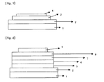
FIG. 1 illustrates an organic light emitting device comprising asubstrate 1, ananode 2, alight emitting layer 3, and a cathode 4; and -
FIG. 2 illustrates an organic light emitting device comprising asubstrate 1, ananode 2, ahole injection layer 5, a hole transport layer 6, alight emitting layer 7, an electron transport layer 8, and a cathode 4. - A substituent group of Formula 1 will be described in detail below.
- In R1 to R7 of Formula 1, the number of carbon atoms of the alkyl group, the alkoxy group, and the alkenyl group is not particularly limited, but it is preferable that it is in the range of 1 to 20.
- The length of the alkyl group that is included in the compound does not affect the conjugation length of the compound, but may auxiliarily affect an application method of the compound to the organic light emitting device, for example, the application of a vacuum deposition method or a solution coating method.
- Illustrative, but non-limiting, examples of the aryl group of R1 to R7 of
Formula 1 include monocyclic aromatic rings, such as a phenyl group, a biphenyl group, a terphenyl group, and a stilbene group, and multicyclic aromatic rings, such as a naphthyl group, an anthracenyl group, a phenanthrene group, a pyrenyl group, and a perylenyl group. - Illustrative, but non-limiting, examples of the hetero ring group of R1 to R7 of
Formula 1 include a thiophenyl group, a furan group, a pyrrolyl group, an imidazolyl group, a thiazolyl group, an oxazolyl group, an oxadiazolyl group, a triazolyl group, a pyridyl group, a pyradazine group, a quinolinyl group, an isoquinoline group, and an acridyl group. - A of
Formula 1 is an aryl group, and preferably, illustrative, but non-limiting, examples thereof include monocyclic aromatic rings, such as a phenyl group, a biphenyl group, a terphenyl group, and a stilbene group, and multicyclic aromatic rings, such as a naphthyl group, an anthracenyl group, a phenanthrene group, a pyrenyl group, and a perylenyl group. - Illustrative but non-limiting, examples of the heteroring of B include a thiophenyl group, a furan group, a pyrrolyl group, an imidazolyl group, a thiazolyl group, an oxazolyl group, an oxadiazolyl group, a triazolyl group, a pyridyl group, a pyradazine group, a quinolinyl group, an isoquinoline group, and an acridyl group.
- The present invention also relates to a compound that is represented by any one of the following Formula 2 and Formula 3.

- In
Formula 2 andFormula 3, Ar' s are each independently selected from the group consisting of a phenyl group, a biphenyl group, a terphenyl group, a stilbene group, a naphthyl group, an anthracenyl group, a phenanthrene group, a pyrenyl group, a perylenyl group, and Ar, Y and R1 to R8 are the same as definitions in respects to Ar, Y and R1 to R7 ofFormula 1. - In addition, the compound that is represented by Formula 1 may be preferably a compound that is represented by any one of the following Formula 2-1 and Formula 3-1.

- In Formula 2-1 and Formula 3-1, Ar, Y and R1 to R8 are the same as definitions in respects to Ar, Y and R1 to R7 of
Formula 1. - In addition, the compound that is represented by Formula 1 may be preferably a compound that is represented by any one of the following Formula 2-2 and Formula 3-2.


- In Formula 2-2 and Formula 3-2, Ar, Y and R1 to R8 are the same as definitions in respects to Ar, Y and R1 to R7 of
Formula 1. - In addition, in the case of arylamine, illustrative, but non-limiting examples thereof may preferably include the following groups.


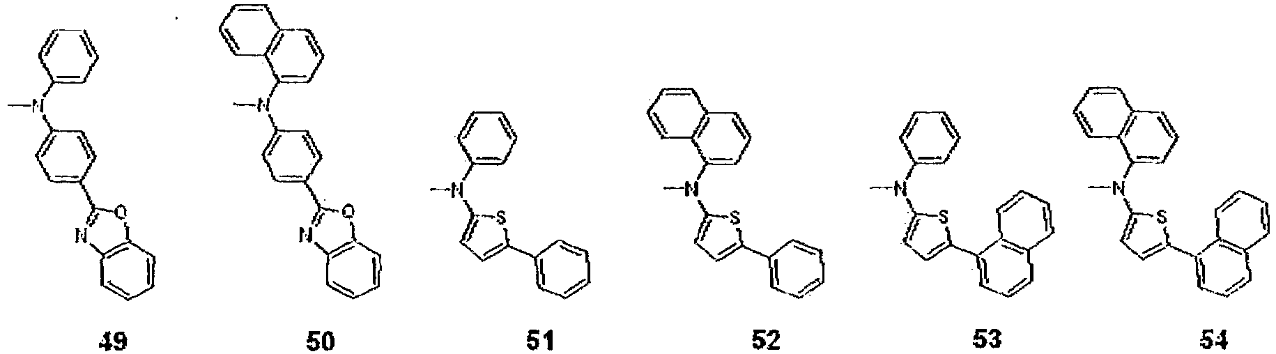


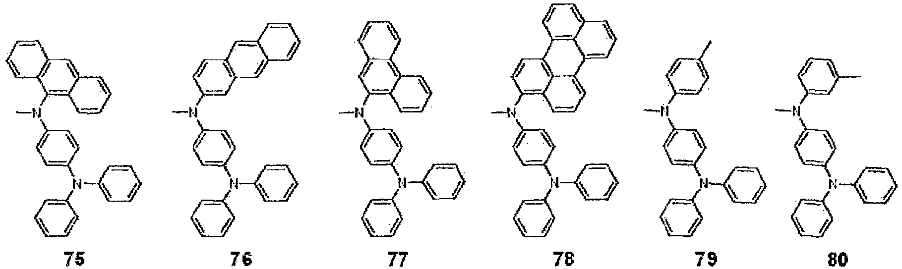
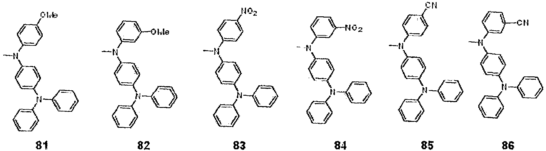


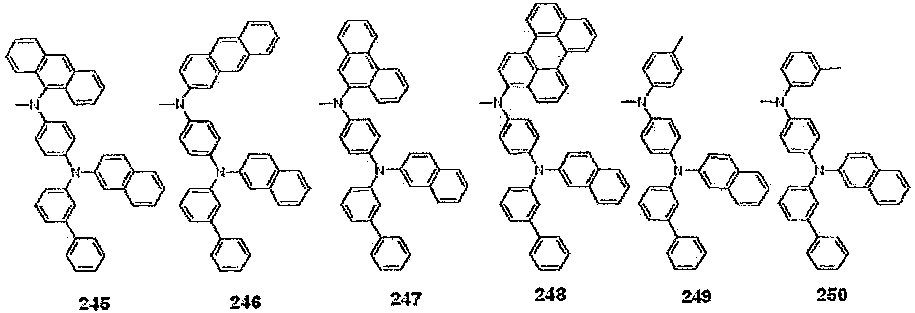


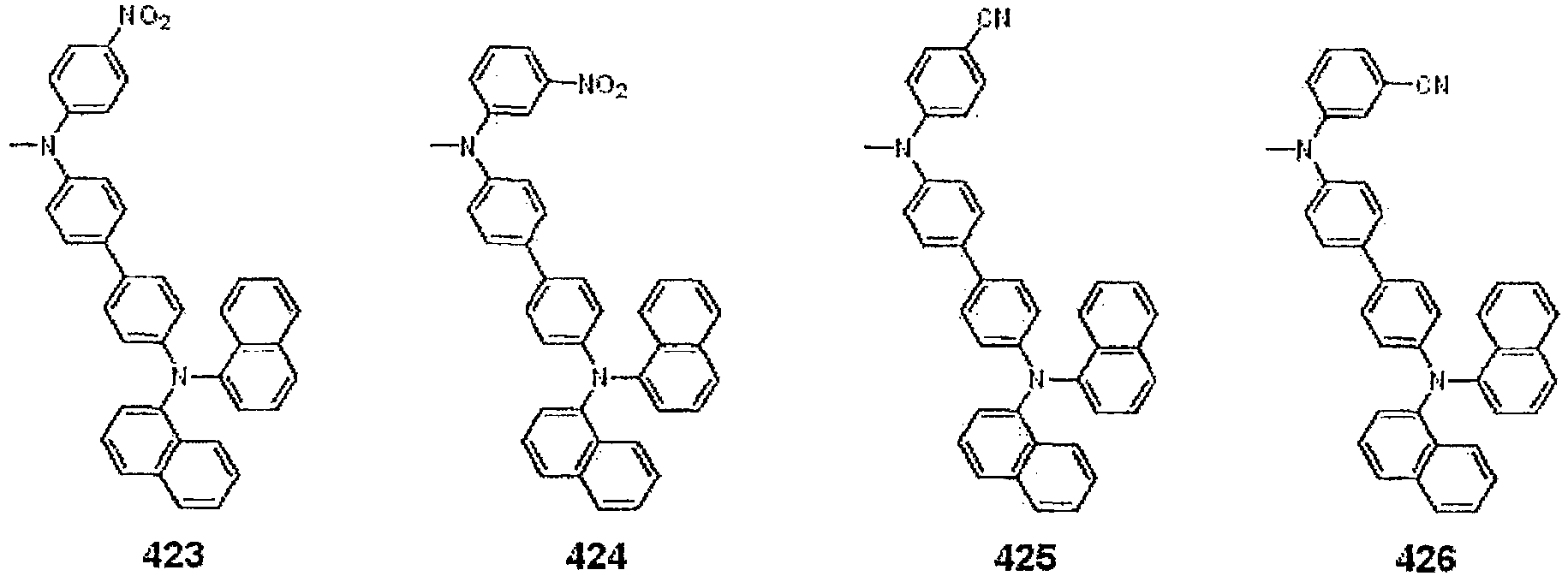


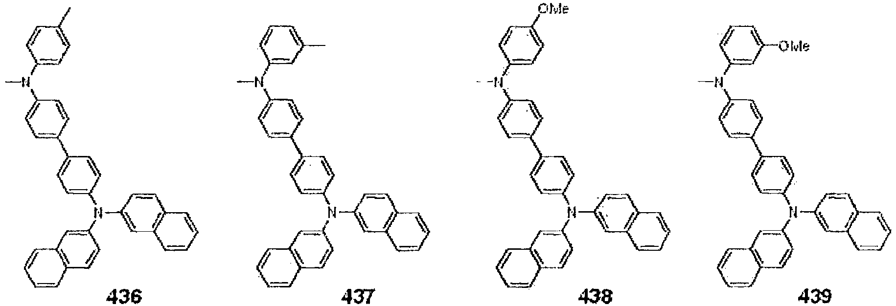


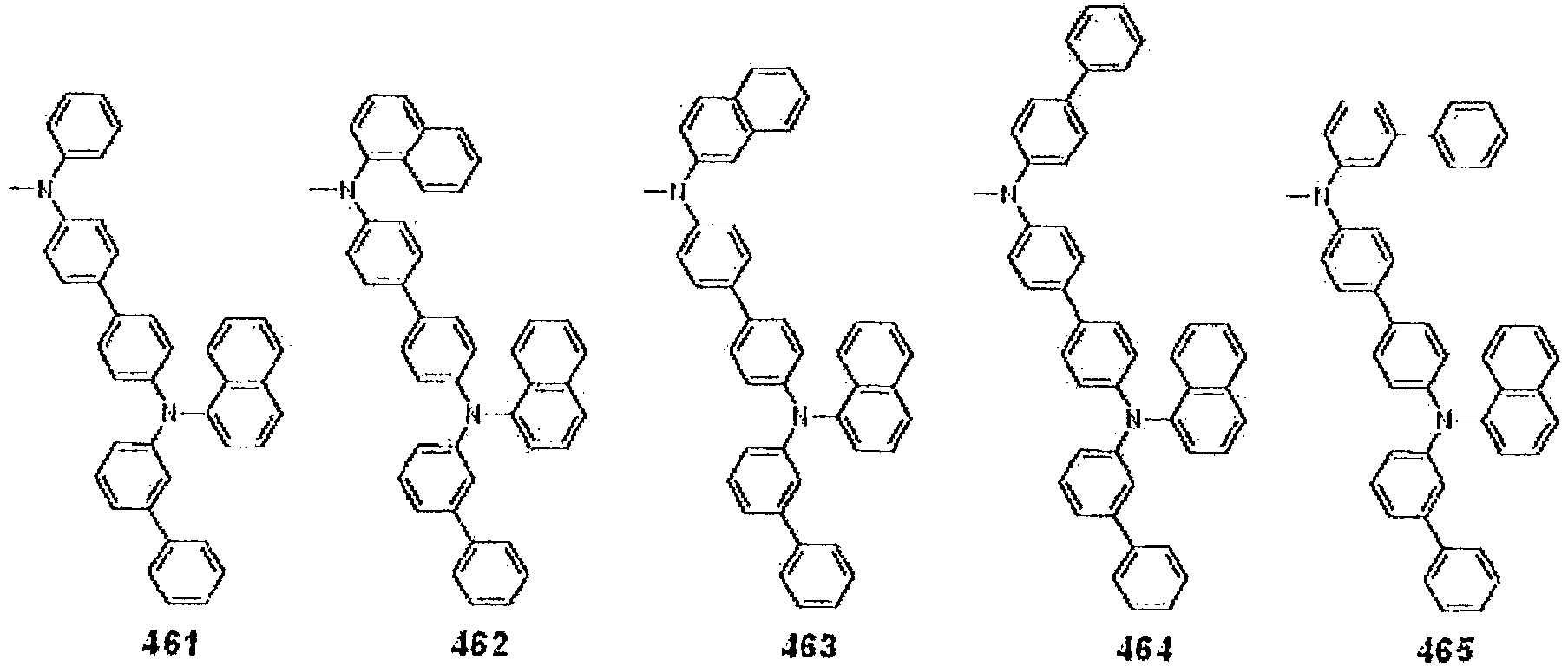


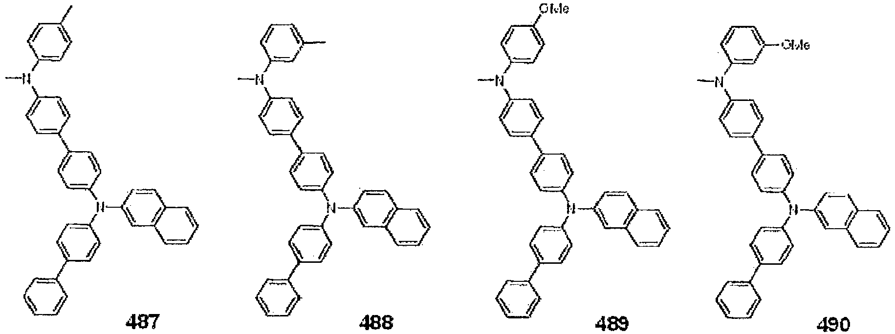


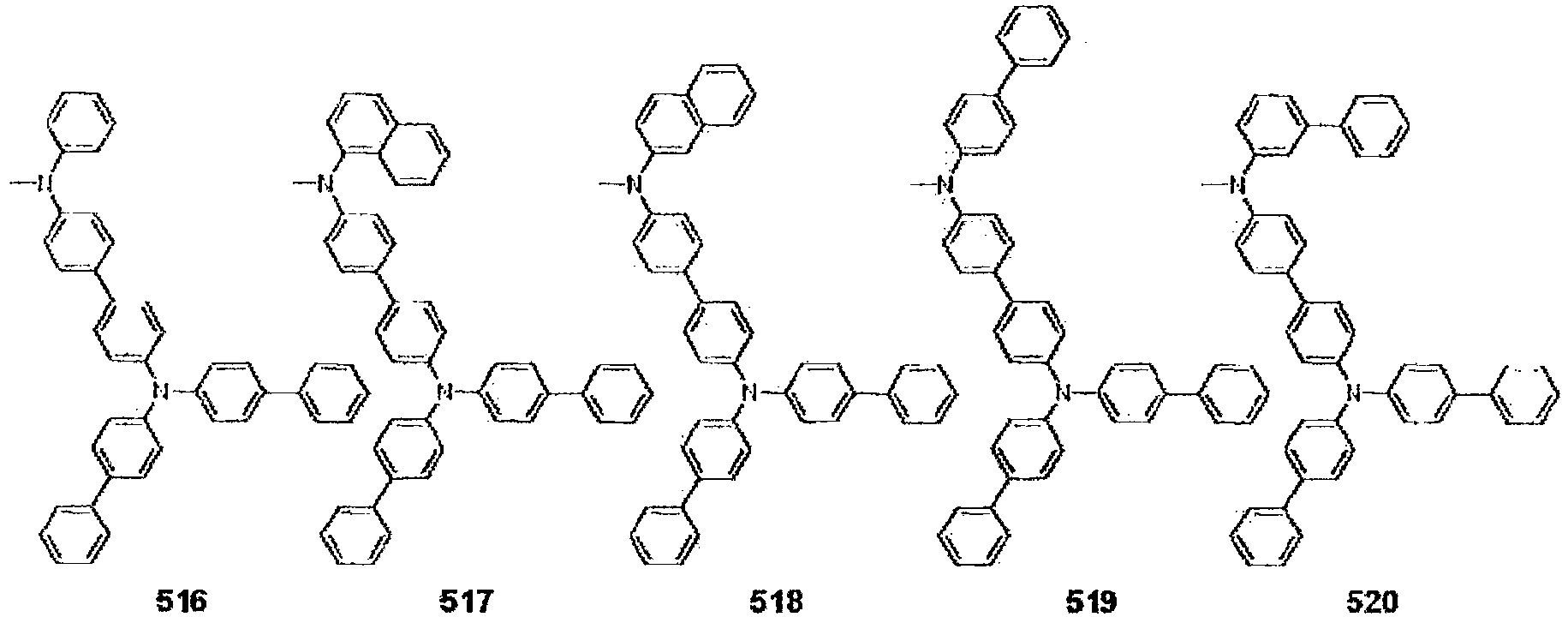


- Ar may be preferably phenylene.
- The compound of Formula 1 may be preferably a compound that is represented by the following Formula 4 to Formula 12.


- The compound of Formula 1 may have a property that is required when it is used as an organic material layer used in an organic light emitting device by using a core structure which is shown in Formula 1, that is, a structure in which arylene is substituted at a carbon position between R5 and R6 of carbazole as a core structure and introducing various substituents into the core structure including a structure that includes each independently hydrogen, heavy hydrogen; aliphatic hydrocarbon having 1-20 carbon atoms; aromatic hydrocarbon; aromatic hydrocarbon which is substituted with one or more substituent groups selected from the group consisting of nitro, nitrile, halogen, an alkyl group, an alkoxy group, an amino group, an aromatic hydrocarbon and a hetero ring group; a silicon group which is substituted with aromatic hydrocarbon; a hetero ring group; a hetero ring group which is substituted with one or more substituent groups selected from the group consisting of nitro, nitrile, halogen, an alkyl group, an alkoxy group, an amino group, an aromatic hydrocarbon and a hetero ring group; a thiophene group which is substituted with hydrocarbon having 1-20 carbon atoms or aromatic hydrocarbon having 6-20 carbon atoms; or a boron group which is substituted with an aromatic hydrocarbon.
- The conjugation length of the compound has a close relationship with an energy band gap. In detail, the energy band gap is reduced as the conjugation length of the compound increases. As described above, since a conjugation structure is limited in the core structure of the compound of
Formula 1, the core structure has a large energy band gap. - As described above, in the present invention, various substituent groups are introduced to R1 to R7 and X and Y positions of the core structure having the large energy band gap so as to produce compounds having various energy band gaps. Generally, it is easy to control an energy band gap by introducing substituent groups into a core structure having a large energy band gap, but it is difficult to signifimaytly control the energy band gap by introducing substituent groups into a core structure having a small energy band gap. Furthermore, in the present invention, it is possible to control HOMO and LUMO energy levels of the compound by introducing various substituent groups into R1 to R7 and X and Y of the core structure.
- Additionally, by introducing various substituent groups into the core structure, compounds having intrinsic characteristics of the substituent groups may be obtained. For example, substituent groups, which are frequently applied to hole injection layer material, hole transport layer material, light emitting layer material, and electron transport layer materials during the production of the organic light emitting device, are introduced into the core structure so as to produce substances capable of satisfying the requirements of each organic material layer.
- Since the core structure of the compound of
Formula 1 includes the amine structure, it has an energy level suitable for the hole injection and/or hole transport materials in the organic light emitting device. In the present invention, the compound having the proper energy level is selected depending on the substituent group among the compounds represented byFormula 1 to be used in the organic light emitting device, thereby it is possible to realize a device having a low driving voltage and a high light efficiency. - Furthermore, various substituent groups are introduced into the core structure so as to precisely control the energy band gap, and to improve interfacial characteristics with organic materials, thereby apply the compound to various fields.
- In addition, by controlling the number of amine that is included in the substitutent group B, HOMO and LUMO energy levels and the energy band gap are capable of being precisely controlled, and interfacial characteristics with organic materials are improved, thereby apply the compound to various fields.
- Meanwhile, since the compound of
Formula 1 has a high glass transition temperature (Tg), it has excellent thermal stability. Such increase in thermal stability is an important factor providing driving stability to the device. - Furthermore, the compound of
Formula 1 may be used to form the organic material layer using a vacuum deposition process or a solution coat ing process during the product ion of the organic light emitting device. In connection with this, illustrative, but non-limiting, examples of the solution coating process include a spin coating process, a dip coating process, an inkjet printing process, a screen printing process, a spray process, and a roll coating process. - The organic light emitting device of the present invention may be produced using known materials through a known process, modified only in that at least one layer of organic material layer(s) include the compound of the present invention, that is, the compound of
Formula 1. - The organic material layer(s) of the organic light emitting device according to the present invention may have a single layer structure, or alternatively, a multilayered structure in which at least two organic material layers are layered. For example, the organic light emitting device of the present invention may comprise a hole injection layer, a hole transport layer, a light emitting layer, an electron transport layer, and an electron injection layer as the organic material layer(s). However, the structure of the organic light emitting device is not limited to this, but may comprise a smaller number of organic material layers.
- Furthermore, the organic light emitting device of the present invention may be produced, for example, by sequentially layering a first electrode, organic material layer(s), and a second electrode on a substrate. In connection with this, a physical vapor deposition (PVD) method, such as a sputtering method or an e-beam evaporation method, may be used, but the method is not limited to these.
- A better understanding of a method of manufacturing an compound represented by
Formula 1 may be obtained in light of the following Preparation Examples. However, the following Preparation Examples and Experimental Examples are set forth to illustrate, but are not to be construed to limit the present invention. -


- After 2-bromothiopene (20 g, 122.7 mmol) and phenyl boronic acid (18 g, 147.6 mmol) were dissolved in tetrahydrofuran (300 ml), 4N potassium carbonate aqueous solution (130 mL) and tetrakis(triphenylphosphine)palladium (0) (2.9 g, 2.5 mmol) and were put thereinto and heated while being agitated. After the reaction was finished, the organic layer was separated and dried by using anhydrous magnesium sulfate. After it was distilled under the reduced pressure, it was recrystallized by using hexane to obtain a compound A (14.6 g, yield 74%; [M+H]+ = 161).
- The compound A (18 g, 112.3 mmol) that was manufactured in Preparation Example 1-1 was dissolved in anhydrous tetrahydrofuran, n-butyl lithium (2.5M hexane solution, 49.4 mL, 123.5 mmol) was added dropwise at -78°C, and agitated for 1 hour. Trimethyl borate (15.1 g, 145.3 mmol) was put thereinto, agitated for 1 hour, 2N hydrochloric acid aqueous solution (80 mL) was put thereinto, and it was heated to normal temperature. After the organic layer was separated, it was dried by using anhydrous magnesium sulfate. After it was distilled under the reduced pressure, it was recrystallized by using hexane to obtain a compound B (15.2 g, yield 66%; [M+H]+ = 205).
- The compound B (15 g, 73.5 mmol) that was manufactured in Example 1-2 and 4-bromo-3-iodobenzene (20.8 g, 73.5 mmol) were dissolved in tetrahydrofuran (250 ml), 4N potassium carbonate aqueous solution (75 mL) and tetrakis(triphenylphosphine)palladium (0) (1.7 g, 1.5 mmol) and were put thereinto and heated while being agitated. After the reaction was finished, the organic layer was separated and dried by using anhydrous magnesium sulfate. After it was distilled under the reduced pressure, it was recrystallized by using ethanol to obtain a compound C (14.8 g, yield 64%; [M+H]+ = 316).
- After the compound C (14 g, 44.4 mmol) that was manufactured in Preparation Example 1-3, carbazole (7.5 g, 44.9 mmol), sodium-tertiary-butoxide (5.5 g, 57.2 mmol) and bis (tri tertiary-butyl phosphine)palladium (0) (0.23 g, 0.45 mmol) were suspended in xylene (300 ml), they were refluxed while being agitated. After the reaction was finished, it was cooled to normal temperature, and the manufactured solid was filtered. It was sequentially washed by using water and ethanol to obtain a compound D (14.7 g, yield 82%; [M+H]+ = 402)
- The compound D (14 g, 34.9 mmol) that was manufactured in Preparation Example 1-4 was dissolved in chloroform (300 mL), N-bromosuccinimide (6.3 g, 35.4 mmol) was added thereto, and they were agitated at normal temperature. After the reaction was finished, water was poured thereon, and the organic layer was separated, and it was dried by using anhydrous magnesium sulfate. It was distilled under the reduced pressure, and recrystallized by using tetrahydrofuran and ethanol to obtain a compound E (14.3 g, yield 85%; [M+H]+ = 481)
- The compound E (13 g, 27 mmol) that was manufactured in Example 1-5 and the compound B (5.5 g, 27 mmol) that was manufactured in Example 1-2 were dissolved in tetrahydrofuran (200 ml), 4N potassium carbonate aqueous solution (30 mL) and tetrakis(triphenylphosphine)palladium (0) (0.62 g, 0.54 mmol) and were put thereinto and heated while being agitated. After the reaction was finished, the organic layer was separated and dried by using anhydrous magnesium sulfate. After it was distilled under the reduced pressure, it was recrystallized by using tetrahydrofuran and ethanol to obtain Formula 4 (10.7 g, yield 71%; [M+H]+ = 560).
-

- After the compound E (10 g, 20.8 mmol) of Preparation Example 1-5, and phenyl boronic acid (2.7 g, 22.1 mmol) were dissolved in tetrahydrofuran (300 ml), 4N potassium carbonate aqueous solution (25 mL) and tetrakis(triphenylphosphine)palladium (0) (0.49 g, 0.42 mmol) and were put thereinto and heated while being agitated. After the reaction was finished, the organic layer was separated and dried by using anhydrous magnesium sulfate. After it was distilled under the reduced pressure, it was recrystallized by using tetrahydrofuran and hexane to obtain a compound A (8.2 g, yield 83%; [M+H]+ = 478).
- The compound A (8 g, 16.7 mmol) that was manufactured in Preparation Example 2-1 was dissolved in chloroform (200 mL), N-bromosuccinimide (3 g, 16.9 mmol) was added thereto, and they were agitated at normal temperature. After the reaction was finished, water was poured thereon and the manufactured solid was filtered. It was sequentially washed by using water and ethanol to obtain a compound B (8.2 g, yield 88%; [M+H]+ = 557).
- The compound B (5 g, 9 mmol) that was manufactured in Preparation Example 2-2 and the compound B (1.9 g, 9.3 mmol) that was manufactured in Preparation Example 1-2 were dissolved in tetrahydrofuran (150 ml), 4N potassium carbonate aqueous solution (12 mL) and tetrakis(triphenylphosphine)palladium (0) (0.2 g, 0.18 mmol) and were put thereinto and heated while being agitated. After the reaction was finished, the organic layer was separated and dried by using anhydrous magnesium sulfate. After it was distilled under the reduced pressure, it was recrystallized by using tetrahydrofuran and ethanol to obtain Formula 5 (3.9 g, yield 68%; [M+H]+ = 636).
-

- The compound C (10 g, 31.7 mmol) that was manufactured in Preparation Example 1-3 was dissolved in anhydrous tetrahydrofuran, n-butyl lithium (2.5M hexane solution, 13.8 mL, 34.5 mmol) was added dropwise at -78°C, and agitated for 1 hour. Trimethyl borate (4.3 g, 41.4 mmol) was put thereinto, agitated for 1 hour, 2N hydrochloric acid aqueous solution (20 mL) was put thereinto, and it was heated to normal temperature. After the organic layer was separated, it was dried by using anhydrous magnesium sulfate. After it was distilled under the reduced pressure, it was recrystallized by using hexane to obtain a compound A (5.4 g, yield 61%; [M+H]+ = 281).
- The compound A (5 g, 17.8 mmol) that was manufactured in Preparation Example 3-1 and the compound E (8.5 g, 17.7 mmol) that was manufactured in Preparation Example 1-5 were dissolved in tetrahydrofuran (150 ml), 4N potassium carbonate aqueous solution (20 mL) and tetrakis(triphenylphosphine)palladium (0) (0.42 g, 0.36 mmol) and were put thereinto and heated while being agitated. After the reaction was finished, the organic layer was separated and dried by using anhydrous magnesium sulfate. After it was distilled under the reduced pressure, it was recrystallized by using tetrahydrofuran and ethanol to obtain Formula 6 (8.2 g, yield 73%; [M+H]+ = 636).
-


- The compound B (15 g, 73.5 mmol) that was manufactured in Preparation Example 1-2 and 3-bromo-1-iodobenzene (20.8 g, 73.5 mmol) were dissolved in tetrahydrofuran (180 ml), 4N potassium carbonate aqueous solution (75 mL) and tetrakis(triphenylphosphine)palladium (0) (1.7 g, 1.5 mmol) and were put thereinto and heated while being agitated. After the reaction was finished, the organic layer was separated and dried by using anhydrous magnesium sulfate. After it was distilled under the reduced pressure, it was subjected to the column separation by using a tetrahydrofuran/hexane = 1/10 solvent to obtain a compound A (14.4 g, yield 62%; [M+H]+ = 316).
- After the compound A (14 g, 44.4 mmol) that was manufactured in Preparation Example 4-1, carbazole (7.5 g, 44.9 mmol), sodium-tertiary-butoxide (5.5 g, 57.2 mmol) and bis (tri tertiary-butyl phosphine)palladium (0) (0.23 g, 0.45 mmol) were suspended in xylene (300 ml), they were refluxed while being agitated. After the reaction was finished, it was cooled to normal temperature, and the manufactured solid was filtered. It was sequentially washed by using water and ethanol to obtain a compound B (15.1 g, yield 85%; [M+H]+ = 402).
- The compound B (15 g, 37.4 mmol) that was manufactured in Preparation Example 4-2 was dissolved in chloroform (300 mL), N-bromosuccinimide (6.7 g, 37.6 mmol) was added thereto, and they were agitated at normal temperature. After the reaction was finished, water was poured thereon, the organic layer was separated, and they were dried by using anhydrous magnesium sul fate. It was distilled under the reduced pressure and recrystallized by using tetrahydrofuran and ethanol to obtain a compound C (14.2 g, yield 79%; [M+H]+ = 481).
- The compound C(13 g, 27 mmol) that was manufactured in Preparation Example 4-3 and 4-chlorophenyl borate (4.3 g, 27.5 mmol) were dissolved in tetrahydrofuran (300 ml), 4N potassium carbonate aqueous solution (33 mL) and tetrakis(triphenylphosphine)palladium (0) (0.62 g, 0.54 mmol) and were put thereinto and heated while being agitated. After the reaction was finished, the organic layer was separated and dried by using anhydrous magnesium sulfate. After it was distilled under the reduced pressure, it was recrystallized by using tetrahydrofuran and ethanol to obtain a compound D (9.5g, yield 69%; [M+H]+ = 512).
- After the compound D (8 g, 15.6 mmol) that was manufactured in Preparation Example 4-4, N-phenyl-1-naphthyl amine (3.8 g, 17.3 mmol), sodium-tertiary-butoxide (2 g, 20.8 mmol) and bis (tri tertiary-butyl phosphine)palladium (0) (0.08 g, 0.16 mmol) were suspended in xylene (300 ml), they were refluxed while being agitated. After the reaction was finished, it was cooled to normal temperature, an acidic white clay was put thereinto, and they were agitated. After it was filtered, it was distilled under the reduced pressure, and subjected to the column separation by using a tetrahydrofuran/hexane = 1/7 solvent to obtain Formula 7 (6.4 g, yield 59%; [M+H]+ = 695).
-

- After the compound D (8 g, 15.6 mmol) that was manufactured in Preparation Example 4-4, bis(4-biphenylyl)amine(5.5 g, 17.1 mmol), sodium-tertiary-butoxide (2 g, 20.8 mmol) and bis (tri tertiary-butyl phosphine)palladium (0) (0.08 g, 0.16 mmol) were suspended in xylene (250 ml), they were refluxed while being agitated. After the reaction was finished, it was cooled to normal temperature, an acidic white clay was put thereinto, and they were agitated. After it was filtered, it was distilled under the reduced pressure, and recrystallized by using tetrahydrofuran and ethanol to obtain Formula 8 (7.8 g, yield 63%; [M+H]+ = 797).
-

- The compound E (10 g, 20.8 mmol) that was manufactured in Preparation Example 1-5 and 4-chlorophenyl borate (3.6 g, 23 mmol) were dissolved in tetrahydrofuran (250 ml), 4N potassium carbonate aqueous solution (22 mL) and tetrakis(triphenylphosphine)palladium (0) (0.49 g, 0.42 mmol) and were put thereinto and heated while being agitated. After the reaction was finished, the organic layer was separated and dried by using anhydrous magnesium sulfate. After it was distilled under the reduced pressure, it was recrystallized by using tetrahydrofuran and ethanol to obtain a compound A (7 g, yield 66%; [M+H]+ = 512).
- After the compound A (5 g, 9.7 mmol) that was manufactured in Preparation Example 6-1, bis(4-biphenylyl)amine (3.4 g, 10.6 mmol), sodium-tertiary-butoxide (1.2 g, 12.6 mmol) and bis (tri tertiary-butyl phosphine)palladium (0) (0.05 g, 0.1 mmol) were suspended in xylene (150 ml), they were refluxed while being agitated. After the reaction was finished, it was cooled to normal temperature, and the manufactured solide was filtered. After the filtered solide was dissolved in chloroform, an acidic white clay was put thereinto, and they were agitated. After it was filtered, it was distilled under the reduced pressure, and recrystallized by using tetrahydrofuran and ethanol to obtain Formula 9 (5.2 g, yield 67%; [M+H]+ = 797).
-

- The compound D (10 g, 19.5 mmol) that was manufactured in Preparation Example 4-4 was dissolved in chloroform (300 mL), N-bromosuccinimide (3.7 g, 20.8 mmol) was added thereto, and they were agitated at normal temperature. After the reaction was finished, water was poured thereon, the organic layer was separated, and they were dried by using anhydrous magnesium sulfate. It was distilled under the reduced pressure and recrystallized by using tetrahydrofuran and ethanol to obtain a compound A (8.9 g, yield 77%; [M+H]+ = 591).
- The compound A (8 g, 13.5 mmol) that was manufactured in Preparat ion Example 7-1 and 4-chlorophenyl borate (2.3 g, 14.7 mmol) were dissolved in tetrahydrofuran (200 ml), 4N potassium carbonate aqueous solution (15 mL) and tetrakis(triphenylphosphine)palladium (0) (0.31 g, 0.27 mmol) and were put thereinto and heated while being agitated. After the reaction was finished, the manufactured solid was filtered. The filtered solid was recrysallized by using tetrahydrofuran and ethanol to obtain a compound B (5.2 g, yield 65%; [M+H]+ = 588).
- After the compound B (5 g, 8.5 mmol) that was manufactured in Preparation Example 7-2, bis(4-biphenylyl)amine (3 g, 9.3 mmol), sodium-tertiary-butoxide (1.1 g, 11.4 mmol) and bis (tri tertiary-butyl phosphine)palladium (0) (0.05 g, 0.1 mmol) were suspended in xylene (150 ml), they were refluxed while being agitated. After the reaction was finished, it was cooled to normal temperature, an acidic white clay was put thereinto, and they were agitated. After it was filtered, it was distilled under the reduced pressure, and recrystallized by using tetrahydrofuran and ethanol to obtain Formula 10 (4.5 g, yield 61%; [M+H]+ = 873).
-

- The compound A (10 g, 19.5 mmol) that was manufactured in Preparation Example 6-1 was dissolved in chloroform (300 mL), N-bromosuccinimide (3.7 g, 20.8 mmol) was added thereto, and they were agitated at normal temperature. After the reaction was finished, water was poured thereon, the organic layer was separated, and they were dried by using anhydrous magnesium sulfate. It was distilled under the reduced pressure and recrystallized by using tetrahydrofuran and ethanol to obtain a compound A (9.4 g, yield 82%; [M+H]+ = 591).
- The compound A (8 g, 13.5 mmol) that was manufactured in Preparation Example 8-1 and the compound B (3 g, 14.7 mmol) that was manufactured in Preparation Example 1-2 were dissolved in tetrahydrofuran (150 ml), 4N potassium carbonate aqueous solution (15 mL) and tetrakis(triphenylphosphine)palladium (0) (0.31 g, 0.27 mmol) and were put thereinto and heated while being agitated. After the reaction was finished, the manufactured solid was filtered. The filtered solid was recrysallized by using tetrahydrofuran and ethanol to obtain a compound B (6.2 g, yield 69%; [M+H]+ = 670).
- After the compound B (6 g, 9 mmol) that was manufactured in Preparation Example 8-2, N-phenyl-1-naphthyl amine (2.1 g, 9.6 mmol), sodium-tertiary-butoxide (1.1 g, 11.7 mmol) and bis (tri tertiary-butyl phosphine)palladium (0) (0.05 g, 0.1 mmol) were suspended in xylene (100 ml), they were refluxed while being agitated. After the reaction was finished, it was cooled to normal temperature, an acidic white clay was put thereinto, and they were agitated. After it was filtered, it was distilled under the reduced pressure, and subjected to the column separation by using a tetrahydrofuran/hexane = 1/6 solvent to obtain Formula 11 (3.8 g, yield 49%; [M+H]+ = 853).
-

- The compound D (10 g, 19.5 mmol) that was manufactured in Preparation Example 4-4 was dissolved in chloroform (300 mL), N-bromosuccinimide (3.7 g, 20.8 mmol) was added thereto, and they were agitated at normal temperature. After the reaction was finished, water was poured thereon, the organic layer was separated, and they were dried by using anhydrous magnesium sulfate. It was distilled under the reduced pressure and recrystallized by using tetrahydrofuran and ethanol to obtain a compound A (9.1 g, yield 79%; [M+H]+ = 591).
- The compound A (9 g, 15.2 mmol) that was manufactured in Preparation Example 9-1 and the compound B (3.4 g, 16.7 mmol) that was manufactured in Preparation Example 1-2 were dissolved in tetrahydrofuran (150 ml), 4N potassium carbonate aqueous solution (18 mL) and tetrakis(triphenylphosphine)palladium (0) (0.35 g, 0.3 mmol) and were put thereinto and heated while being agitated. After the reaction was finished, the manufactured solid was filtered. The filtered solid was recrysallized by using tetrahydrofuran and ethanol to obtain a compound B (7.3 g, yield 72%; [M+H]+ = 670).
- After the compound B (6 g, 9 mmol) that was manufactured in Preparation Example 9-2, bis(4-biphenylyl)amine (3 g, 9.3 mmol), sodium-tertiary-butoxide (1.1 g, 11.4 mmol) and bis (tri tertiary-butyl phosphine)palladium (0) (0.05 g, 0.1 mmol) were suspended in xylene (150 ml), they were refluxed while being agitated. After the reaction was finished, it was cooled to normal temperature, and the manufactured solid was filtered. The filtered solid was dissolved in chloroform, an acidic white clay was put thereinto, and they were agitated and filtered. After it was distilled under the reduced pressure, and recrystallized by using tetrahydrofuran and ethanol to obtain Formula 12 (5.6 g, yield 65%; [M+H]+ = 955).
-
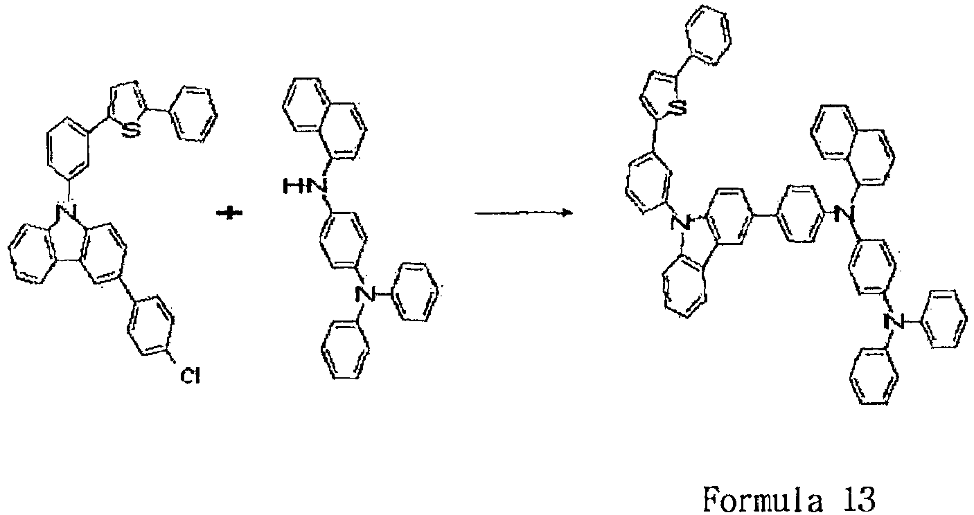
- The compound A (4 g, 7.8 mmol) of the Preparation Example 6 and the amine compound (3.17 g, 8.2 mmol) were dissolved in 150 ml of xylene, sodium-tertiary-butoxide (1.9 g, 19.5 mmol), and 20 mg of Pd[P(t-Bu)3]2 (0.06 mmol) were added, and refluxed for 5 hours under the nitrogen atmosphere.
- Distilled water was put in the react ion solution, the react ion was finished, and the organic layer was extracted. It was subjected to the column separat ion by using a normal-hexane/tetrahydrofuran = 10/1 solvent, agitated in petroleum ether, and vacuum dried to obtain Formula 13 (3.4 g, yield 50%). MS: [M+H]+ = 861
-

- Carbazole (17.5 g, 104.8 mmol) was dissolved in dimethylacet amide (100mL), and 4-chloroiodobenzene (25 g, 104.8mmol), Cu (13.3 g, 209.6mmol), K2CO3 (43.5 g, 314.4 mmol) were put thereinto, and they were refluxed for 12 hours.
- After the reaction solution was filtered, concentrated, and recrystallized by using EtOH to obtain Formula A (24.8g, yield 85%). MS: [M+H]+ = 278
- Formula A (24.8 g, 89.3 mmol) that was manufactured in step (1) was dissolved in chloroform (200 mL), N-bromosuccinic imide (15.9 g, 89.3 mmol) was added thereto, and they were agitated for 5 hours at normal temperature.
- Distilled water was put thereinto the reaction solution, the reaction was finished, and the organic layer was extracted. After the reaction solution was concentrated, the next reaction was performed without the purification process. MS: [M+H]+ = 357
- Formula B (31.7 g, 89 mmol) that was manufactured in step (2) and 4-chlorophenyl boronic acid (15.3 g, 97.9 mmol) were dissolved in THF (150 mL), and Pd(PPh3)4 (2.1 g, 1.78 mmol) and the K2CO3 /H2O aqueous solution (6 g/100 mL, 356 mmol) were put thereinto, and they were refluxed for 24 hours.
- Distilled water was put thereinto the reaction solution, the reaction was finished, and the organic layer was extracted. After the react ion solution was concentrated and subjected to the column separation by using a normal-hexane/tetrahydrofuran = 10/1 solvent, they were agitated in EtOH, filtered, and vacuum dried to obtain Formula C (8.9 g, yield 26%). MS: [M+H]+ = 388
- Formula C (4.9 g, 12.6 mmol) that was manufactured in step (3) and N-phenyl-1-naphthyl amine (6.9 g, 31.5 mmol) were dissolved in 150 ml of xylene, sodium-tertiary-butoxide (3 g, 31.5 mmol), bisdibenzylideneacetonepalladium (0) (0.28 g, 0.5 mmol), and 50 wt% tri-tertiary-butylphosphine toluene solution (0.24ml, 0.5 mmol) were added thereto, and refluxed for 5 hours under the nitrogen atmosphere.
- Distilled water was put in the reaction solution, the react ion was finished, and the organic layer was extracted. It was subjected to the column separation by using a normal-hexane/tetrahydrofuran = 10/1 solvent, agitated in EtOH, filtered, and vacuum dried to obtain Formula 14 (1.8 g, yield 19%). MS: [M+H]+ = 754
-

- Formula C (4 g, 10.3 mmol) that was manufactured in step (3) of Preparation Example 11 and bisdiphenylamine (8.28 g, 25.8 mmol) were dissolved in 150 ml of xylene, sodium-tertiary-butoxide (2.47 g, 25.8 mmol), and Pd[P(t-Bu)3]2 (0.2 g, 0.4 mmol) were added thereto, and ref luxed for 5 hours under the nitrogen atmosphere.
- Distilled water was put in the reaction solution, the reaction was finished, and the organic layer was extracted. It was subjected to the column separation by using a normal-hexane/tetrahydrofuran = 10/1 solvent, agitated in petroleum ether, and vacuum dried to obtain Formula 15 (6.9 g, yield 70%). MS: [M+H]+ = 958
- A glass substrate, on which ITO (indium tin oxide) was applied to a thickness of 1500 Å to form a thin film, was put in distilled water, in which a detergent was dissolved, and washed using ultrasonic waves. In connection with this, a product manufactured by Fischer Inc. was used as the detergent, and distilled water was produced by filtering twice using a filter manufactured by Millipore Inc. After ITO was washed for 30 min, ultrasonic washing was conducted twice using distilled water for 10 min. After the washing using distilled water was completed, ultrasonic washing was conducted using isopropyl alcohol, acetone, and methanol solvents, and drying was then conducted. Next, it was transported to a plasma washing machine. In addition, the substrate was washed using oxygen plasma 85 W for 5 min, and then transported to a vacuum evaporator.
- Hexanitrile hexaazatriphenylene (hereinafter, referred to as "HAT") of the following Formula was vacuum deposited to a thickness of 500 Å by heating on a transparent ITO electrode, which was prepared through the above procedure, so as to form a hole injection layer.

- The compound of Formula 4, which was prepared in Example 1, was vacuum deposited to a thickness of 400 Å by heating on the hole injection layer so as to form a hole transport layer.
- Subsequently, on the hole transport layer, GH and GD as described below were vacuum deposited to a film thickness of 300 Å at a film thickness ratio of 20:1 so as to form a light emitting layer.

- On the light emitting layer, the electron transport material as described below was vacuum deposited to a thickness of 200 Å so as to form an electron injection layer and a electron transport layer.
-

- Lithium fluoride (LiF) having a thickness of 12 Å and aluminum having a thickness of 2000 Å were sequentially deposited on the electron injection layer and the electron transport layer to form a cathode.
- In the above procedure, the deposition speed of an organic material was maintained at 0.4 to 0.7 Å/sec, lithium fluoride and aluminum were deposited at speeds of 0.3 Å/sec and 2 Å/sec, respectively, on the cathode, and in the deposition, a vacuum was maintained at 2 X 10⁻⁷ to 5 X 10⁻⁸ torr.
- A forward current density of 4.8 V was applied to the light emitting device manufactured in the above, and as a result, the green light in which the color coordinate was (0.32, 0.66) at a current density of 50 mA/cm2 was observed at 26 cd/A, and a life span to the luminance of 90% was 180 hours.
- The same process was performed to manufacture an organic EL device, except that the compound of
Formula 5 was used instead of the compound of Formula 4 in Experimental Example 1. - A forward current density of 4.7 V was applied to the light emitting device manufactured in the above, and as a result, the green light in which the color coordinate was (0.33, 0.64) at a current density of 50 mA/cm2 was observed at 27 cd/A, and a life span to the luminance of 90% was 200 hours.
- The same process was performed to manufacture an organic EL device, except that the compound of Formula 6 was used instead of the compound of Formula 4 in Experimental Example 1.
- A forward current density of 4.8 V was applied to the light emitting device manufactured in the above, and as a result, the green light in which the color coordinate was (0.33, 0.65) at a current density of 50 mA/cm2 was observed at 29 cd/A, and a life span to the luminance of 90% was 210 hours.
- The same process was performed to manufacture an organic EL device, except that the compound of
Formula 7 was used instead of the compound of Formula 4 in Experimental Example 1. - A forward current density of 4.6 V was applied to the light emitting device manufactured in the above, and as a result, the green light in which the color coordinate was (0.32, 0.65) at a current density of 50 mA/cm2 was observed at 28 cd/A, and a life span to the luminance of 90% was 190 hours.
- The same process was performed to manufacture an organic EL device, except that the compound of Formula 8 was used instead of the compound of Formula 4 in Experimental Example 1.
- A forward current density of 4.7 V was applied to the light emitting device manufactured in the above, and as a result, the green light in which the color coordinate was (0.32, 0.64) at a current density of 50 mA/cm2 was observed at 30 cd/A, and a life span to the luminance of 90% was 250 hours.
- The same process was performed to manufacture an organic EL device, except that the compound of Formula 9 was used instead of the compound of Formula 4 in Experimental Example 1.
- A forward current density of 4.6 V was applied to the light emitting device manufactured in the above, and as a result, the green light in which the color coordinate was (0.31, 0.65) at a current density of 50 mA/cm2 was observed at 29 cd/A, and a life span to the luminance of 90% was 240 hours.
- The same process was performed to manufacture an organic EL device, except that the compound of Formula 10 was used instead of the compound of Formula 4 in Experimental Example 1.
- A forward current density of 4.5 V was applied to the light emitting device manufactured in the above, and as a result, the green light in which the color coordinate was (0.32, 0.65) at a current density of 50 mA/cm2 was observed at 31 cd/A, and a life span to the luminance of 90% was 270 hours.
- The same process was performed to manufacture an organic EL device, except that the compound of Formula 11 was used instead of the compound of Formula 4 in Experimental Example 1.
- A forward current density of 4.4 V was applied to the light emitting device manufactured in the above, and as a result, the green light in which the color coordinate was (0.32, 0.66) at a current density of 50 mA/cm2 was observed at 31 cd/A, and a life span to the luminance of 90% was 270 hours.
- The same process was performed to manufacture an organic EL device, except that the compound of Formula 12 was used instead of the compound of Formula 4 in Experimental Example 1.
- A forward current density of 4.4 V was applied to the light emitting device manufactured in the above, and as a result, the green light in which the color coordinate was (0.33, 0.65) at a current density of 50 mA/cm2 was observed at 32 cd/A, and a life span to the luminance of 90% was 280 hours.
- The same process was performed to manufacture an organic EL device, except that 4,4'-bis[N-(1-naphthyl)-N-phenylamino]biphenyl (NPB) of the following Formula was used instead of the compound of Formula 4 in Experimental Example 1.

- A forward current density of 4.6 V was applied to the light emitting device manufactured in the above, and as a result, the green light in which the color coordinate was (0.32, 0.64) at a current density of 50 mA/cm2 was observed at 26 cd/A, and a life span to the luminance of 90% was 140 hours.
- A compound according to the present invention is conf igured so that stability in respects to a hole and an electron is increased while properties of carbazole are not largely changed by introducing heavy hydrogen to carbazole. These compounds may be used as an organic material layer material, particularly, a hole injection material and/or a hole transport material in an organic light emitting device, and in the case of when it is used in the organic light emitting device, a driving voltage of the device may be reduced, light efficiency may be improved, and a life span property of the device may be improved because of thermal stability of the compound.
Claims (10)
- A compound of the following Formula 1, Formula 3, Formula 4 or Formula 5:

Ar is an arylene group having 6 to 40 carbon atoms, which is substituted or unsubstituted with one or more substituent groups selected from the group consisting of nitro, nitrile, halogen, an alkyl group, an alkoxy group and an amino group, or a divalent hetero ring group, which is substituted or unsubstituted with one or more substituent groups selected from the group consisting of nitro, nitrile, halogen, an alkyl group, an alkoxy group and an amino group;
Ar' is each independently selected from the group consisting of a phenyl group, a biphenyl group, a terphenyl group, a stilbene group, a naphthyl group, an anthracenyl group, a phenanthrene group, a pyrenyl group and a perylenyl group,
A is an aryl group, which is substituted or unsubstituted with one or more substituent groups selected from the group consisting of a halogen group, an alkyl group, an alkenyl group, an alkoxy group, a substituted or unsubstituted arylamine group, a substituted or unsubstituted aryl group, a substituted or unsubstituted arylalkyl group, a substituted or unsubstituted arylalkenyl group, a substituted or unsubstituted hetero ring group, a nitrile group and an acetylene group,
B is a hetero ring group including O or S as a heteroatom, which is substituted or unsubstituted with one or more substituent groups selected from the group consisting of a halogen group, an alkyl group, an alkenyl group, an alkoxy group, a substituted or unsubstituted arylamine group, a substituted or unsubstituted aryl group, a substituted or unsubstituted arylalkyl group, a substituted or unsubstituted arylalkenyl group, a substituted or unsubstituted hetero ring group, a nitrile group and an acetylene group,
m and n are an integer in the range of 1 to 10, respectively,
Y is an arylamine group, which is substituted or unsubstituted with one or more substituent groups selected from the group consisting of a halogen group, an alkyl group, an alkenyl group, an alkoxy group, a substituted or unsubstituted arylamine group, a substituted or unsubstituted aryl group, a substituted or unsubstituted arylalkyl group, a substituted or unsubstituted arylalkenyl group, a substituted or unsubstituted hetero ring group, a nitrile group and an acetylene group; or a hetero ring group including O , N or S as a heteroatom, which is substituted or unsubstituted with one or more substituent groups selected from the group consisting of a halogen group, an alkyl group, an alkenyl group, an alkoxy group, a substituted or unsubstituted arylamine group, a substituted or unsubstituted aryl group, a substituted or unsubstituted arylalkyl group, a substituted or unsubstituted arylalkenyl group, a substituted or unsubstituted hetero ring group, a nitrile group and an acetylene group, and
R1 to R8 are each independently selected from the group consisting of hydrogen; an alkyl group, which is substituted or unsubstituted with one or more substituent groups selected from the group consisting of a halogen group, an alkyl group, an alkenyl group, an alkoxy group, a substituted or unsubstituted aryl group, a substituted or unsubstituted arylalkyl group, a substituted or unsubstituted arylalkenyl group, a substituted or unsubstituted hetero ring group, a nitrile group and an acetylene group; an alkoxy group, which is substituted or unsubstituted with one or more substituent groups selected from the group consisting of a halogen group, an alkyl group, an alkenyl group, an alkoxy group, a substituted or unsubstituted aryl group, a substituted or unsubstituted arylalkyl group, a substituted or unsubstituted arylalkenyl group, a substituted or unsubstituted hetero ring group, a nitrile group and an acetylene group; an aryl group, which is substituted or unsubstituted with one or more substituent groups selected from the group consisting of a halogen group, an alkyl group, an alkenyl group, an alkoxy group, a substituted or unsubstituted aryl group, a substituted or unsubstituted arylalkyl group, a substituted or unsubstituted arylalkenyl group, a substituted or unsubstituted hetero ring group, a nitrile group and an acetylene group; an amino group, which is substituted with one or more substituent groups selected from the group consisting of an alkyl group, an alkenyl group, a substituted or unsubstituted aryl group, a substituted or unsubstituted arylalkyl group, and a substituted or unsubstituted arylalkenyl group; a nitro group; and a halogen group, and said R1 to R8 may form an aliphatic or hetero condensation ring in conjunction with adjacent groups,

- The compound as set forth in claim 1, wherein A of Formula 1 is selected from the group consisting of a phenyl group, a biphenyl group, a terphenyl group, a stilbene group, a naphthyl group, an anthracenyl group, a phenanthrene group, a pyrenyl group and a perylenyl group.
- The compound as set forth in claim 1, wherein B of Formula 1 is a hetero ring, which is selected from the group consisting of a thiophene group and furan group;
and
Y of Formula 1 is a hetero ring, it is selected from the group consisting of a thiophene group, a furan group, a pyrrolyl group, an imidazolyl group, a thiazolyl group, an oxazolyl group, an oxadiazolyl group, a triazolyl group, a pyridyl group, a quinolinyl group, an isoquinoline group, and an acridyl group. - The compound as set forth in claim 1, wherein the compound of Formula 1 is represented by the following Formula 2:

- The compound as set forth in claim 1, wherein the compound of Formula 1 is represented by the following Formula 2-1 and the compound of Formula 3 is represented by the following Formula 3-1:

- The compound as set forth in claim 1, wherein the compound of Formula 1 is represented by the following Formula 2-2 and the compound of Formula 3 is represented by the following Formula 3-2:
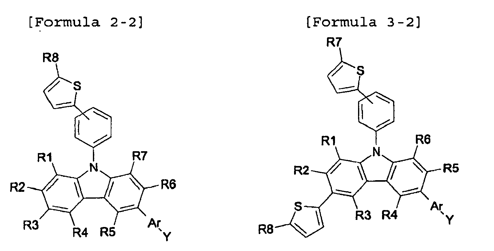
- The compound as set forth in claim 1, wherein when Y of Formula 1 or formula 3 is arylamine, it is any one of the following groups:


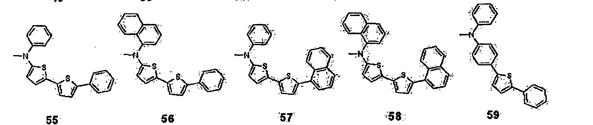


- The compound as set forth in claim 1, wherein Ar of Formula 1 or Formula 3 is phenylene.
- The compound as set forth in claim 1, wherein the compound of Formula 1 or Formula 3 is any one compound of the following Formula 6 to Formula 13:


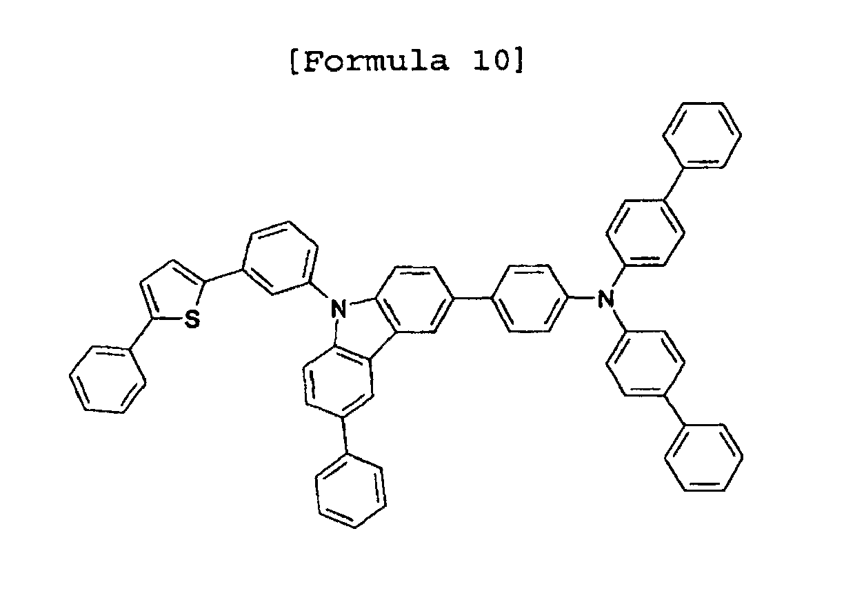


- An organic light emitting device that includes a first electrode, an organic material layer that includes one or more layers having a light emitting layer, and a second electrode sequentially layered,
wherein the organic light emitting device comprises one or more layers of the organic material layer that includes a hole transport layer, a hole injection layer, a hole transport and injection layer, or an electron injection and transport layer, and
the hole transport layer, the hole injection layer, the hole transport and injection layer, the electron injection and transport layer, or the light emitting layer include the compound of Formula 1, Formula 3, Formula 4 or Formula 5 as defined in claim 1.
Applications Claiming Priority (2)
| Application Number | Priority Date | Filing Date | Title |
|---|---|---|---|
| KR20070113852 | 2007-11-08 | ||
| PCT/KR2008/006588 WO2009061156A1 (en) | 2007-11-08 | 2008-11-07 | New compound and organic light emitting device using the same |
Publications (3)
| Publication Number | Publication Date |
|---|---|
| EP2215182A1 EP2215182A1 (en) | 2010-08-11 |
| EP2215182A4 EP2215182A4 (en) | 2011-08-24 |
| EP2215182B1 true EP2215182B1 (en) | 2014-01-08 |
Family
ID=40625953
Family Applications (2)
| Application Number | Title | Priority Date | Filing Date |
|---|---|---|---|
| EP08847358.2A Active EP2215182B1 (en) | 2007-11-08 | 2008-11-07 | Carbazole derivative and organic light emitting device using same |
| EP08847615.5A Active EP2215183B1 (en) | 2007-11-08 | 2008-11-07 | New compound and organic light emitting device using the same |
Family Applications After (1)
| Application Number | Title | Priority Date | Filing Date |
|---|---|---|---|
| EP08847615.5A Active EP2215183B1 (en) | 2007-11-08 | 2008-11-07 | New compound and organic light emitting device using the same |
Country Status (7)
| Country | Link |
|---|---|
| US (2) | US8395143B2 (en) |
| EP (2) | EP2215182B1 (en) |
| JP (3) | JP5566898B2 (en) |
| KR (3) | KR20090048299A (en) |
| CN (2) | CN101855315B (en) |
| TW (2) | TWI403503B (en) |
| WO (1) | WO2009061156A1 (en) |
Families Citing this family (59)
| Publication number | Priority date | Publication date | Assignee | Title |
|---|---|---|---|---|
| KR20090048299A (en) * | 2007-11-08 | 2009-05-13 | 주식회사 엘지화학 | New organic light emitting device material and organic light emitting device using same |
| KR20170020544A (en) * | 2007-12-03 | 2017-02-22 | 가부시키가이샤 한도오따이 에네루기 켄큐쇼 | Carbazole derivative, and light-emitting element, light-emitting device, and electronic device using carbazole derivative |
| KR101600127B1 (en) | 2008-11-25 | 2016-03-04 | 이데미쓰 고산 가부시키가이샤 | Aromatic amine derivative, and organic electroluminescent element |
| CN102325751A (en) * | 2009-02-18 | 2012-01-18 | 出光兴产株式会社 | Aromatic amine derivative and organic electroluminescent element |
| KR20100106014A (en) * | 2009-03-23 | 2010-10-01 | 다우어드밴스드디스플레이머티리얼 유한회사 | Novel organic electroluminescent compounds and organic electroluminescent device using the same |
| JP2010254671A (en) | 2009-03-31 | 2010-11-11 | Semiconductor Energy Lab Co Ltd | Carbazole derivative, light emitting element material, light emitting element, light emitting device, electronic device, and lighting device |
| US8877356B2 (en) | 2009-07-22 | 2014-11-04 | Global Oled Technology Llc | OLED device with stabilized yellow light-emitting layer |
| JP5617202B2 (en) * | 2009-07-24 | 2014-11-05 | 三菱化学株式会社 | Organic compound, charge transport material, composition for organic electroluminescence device, organic electroluminescence device, organic EL display and organic EL lighting |
| CN102414176A (en) | 2009-08-27 | 2012-04-11 | 三菱化学株式会社 | Monoamine compound, charge transport material, composition for charge transport film, organic electroluminescence element, organic EL display device, and organic EL lighting |
| KR101137385B1 (en) | 2009-08-28 | 2012-04-20 | 삼성모바일디스플레이주식회사 | Heteroarylamine compound and organic luminescence display device using the same |
| EP2471771B1 (en) * | 2009-08-28 | 2016-11-16 | Hodogaya Chemical Co., Ltd. | Compound having carbazole ring structure and organic electroluminescent device |
| KR101127579B1 (en) * | 2009-08-28 | 2012-03-23 | 삼성모바일디스플레이주식회사 | Amine compound and organic luminescence display device using the same |
| WO2011055932A2 (en) * | 2009-11-05 | 2011-05-12 | 덕산하이메탈(주) | Organic compound, organic electronic device using same, and terminal for same |
| KR101322828B1 (en) | 2009-11-05 | 2013-10-25 | 덕산하이메탈(주) | Organic Chemical and Organic Electronic Element using the same, Terminal thereof |
| KR101007516B1 (en) * | 2010-04-23 | 2011-01-14 | 주식회사 이엘엠 | Organic electroluminescent composition and organic electroluminescent device comprising same |
| KR101311935B1 (en) | 2010-04-23 | 2013-09-26 | 제일모직주식회사 | Compound for organic photoelectric device and organic photoelectric device including the same |
| EP2421064B1 (en) | 2010-08-18 | 2018-07-04 | Cheil Industries Inc. | Compound for organic optoelectronic device, organic light emmiting diode including the same and display including the light emmiting diode |
| JP5623996B2 (en) | 2010-09-21 | 2014-11-12 | 株式会社半導体エネルギー研究所 | Carbazole derivatives |
| JP5872861B2 (en) | 2010-11-30 | 2016-03-01 | 株式会社半導体エネルギー研究所 | Carbazole compounds |
| TW201238113A (en) * | 2011-02-10 | 2012-09-16 | Du Pont | Process and materials for making contained layers and devices made with same |
| EP2688120B1 (en) * | 2011-03-14 | 2017-08-23 | Toray Industries, Inc. | Light-emitting element material and light-emitting element |
| KR101298483B1 (en) * | 2011-04-01 | 2013-08-21 | 덕산하이메탈(주) | Chemical and Organic Electronic Element using the same, Electronic Device thereof |
| WO2012177006A2 (en) * | 2011-06-22 | 2012-12-27 | 덕산하이메탈(주) | Compound for organic electronics, organic electronics using same, and electronic device for same |
| WO2013118846A1 (en) | 2012-02-10 | 2013-08-15 | 出光興産株式会社 | Aromatic amine derivative, organic electroluminescent element and electronic device |
| KR101932563B1 (en) | 2012-06-27 | 2018-12-28 | 삼성디스플레이 주식회사 | Organic light-emitting device comprising multi-layered hole transporting layer, and organic light-emitting display apparatus including the same |
| KR102169273B1 (en) * | 2012-07-26 | 2020-10-23 | 주식회사 동진쎄미켐 | Organic electroluminescent compound comprising acridine derivative and organic electroluminescent device comprising same |
| CN104508850B (en) * | 2012-08-03 | 2017-03-22 | 株式会社半导体能源研究所 | Light-emitting element, light-emitting device, electronic device, and lighting device |
| KR101415730B1 (en) * | 2012-08-07 | 2014-07-04 | (주)위델소재 | Aromatic compound derivatives and organic electroluminescent device using the same |
| KR101483933B1 (en) * | 2012-10-17 | 2015-01-19 | 롬엔드하스전자재료코리아유한회사 | Novel organic electroluminescence compounds and organic electroluminescence device containing the same |
| KR102086546B1 (en) * | 2012-10-19 | 2020-03-10 | 삼성디스플레이 주식회사 | Compound for organic light emitting device and organic light emitting device comprising the same |
| CN104837834B (en) * | 2012-12-07 | 2018-04-03 | 出光兴产株式会社 | Aromatic amine derivative and organic electroluminescent element |
| KR102026645B1 (en) * | 2013-02-07 | 2019-09-30 | 덕산네오룩스 주식회사 | Compound for an organic electronic element, organic electronic element using the same, and an electronic device thereof |
| KR102065656B1 (en) * | 2013-02-19 | 2020-01-13 | 덕산네오룩스 주식회사 | Compound for organic electronic element, organic electronic element using the same, and an electronic device thereof |
| KR102120891B1 (en) * | 2013-02-22 | 2020-06-10 | 삼성디스플레이 주식회사 | Heterocyclic compound and organic light emitting device comprising the same |
| KR101979651B1 (en) * | 2013-04-01 | 2019-05-17 | 덕산네오룩스 주식회사 | Compound for organic electronic element, organic electronic element using the same, and an electronic device thereof |
| KR102223672B1 (en) | 2013-08-19 | 2021-03-08 | 삼성디스플레이 주식회사 | Amine-based compound and organic light emitting diode comprising the same |
| JP2015122459A (en) * | 2013-12-25 | 2015-07-02 | 三星ディスプレイ株式會社Samsung Display Co.,Ltd. | Organic EL element |
| KR102253438B1 (en) | 2014-03-26 | 2021-05-20 | 삼성디스플레이 주식회사 | Amine-based compound and organic light emitting device comprising the same |
| JP6674892B2 (en) * | 2014-07-09 | 2020-04-01 | 保土谷化学工業株式会社 | Organic electroluminescence device |
| WO2016026122A1 (en) * | 2014-08-21 | 2016-02-25 | Dow Global Technologies Llc | Benzocyclobutenes derived compositions, and electronic devices containing the same |
| WO2016088759A1 (en) * | 2014-12-05 | 2016-06-09 | 保土谷化学工業株式会社 | Organic electroluminescent element |
| JP6446254B2 (en) | 2014-12-15 | 2018-12-26 | 三星ディスプレイ株式會社Samsung Display Co.,Ltd. | Carbazole compound, material for organic electroluminescence device, and organic electroluminescence device |
| EP3240057B1 (en) * | 2014-12-24 | 2021-04-07 | Hodogaya Chemical Co., Ltd. | Organic electroluminescent element |
| CN107406382A (en) * | 2014-12-29 | 2017-11-28 | 陶氏环球技术有限责任公司 | Composition and the display device that is produced from it of 2,3 disubstituted indoles as charge transport materials |
| JP6632998B2 (en) * | 2015-01-08 | 2020-01-22 | 保土谷化学工業株式会社 | Organic electroluminescence device |
| WO2016111301A1 (en) * | 2015-01-08 | 2016-07-14 | 保土谷化学工業株式会社 | Organic electroluminescent element |
| US10566540B2 (en) * | 2015-02-03 | 2020-02-18 | Hodogaya Chemical Co., Ltd. | Organic electroluminescent device |
| JP6282614B2 (en) * | 2015-06-22 | 2018-02-21 | ユニバーサル ディスプレイ コーポレイション | Solution processable doped triarylamine hole injection material |
| KR102359879B1 (en) * | 2015-06-25 | 2022-02-10 | 덕산네오룩스 주식회사 | Compound For Organic Electronic Element, Organic Electronic Element Using the Same, and An Electronic Device Thereof |
| CN108431173A (en) * | 2015-12-24 | 2018-08-21 | 陶氏环球技术有限责任公司 | Polymer layer and organic electronic device comprising same |
| WO2017118238A1 (en) * | 2016-01-07 | 2017-07-13 | 广州华睿光电材料有限公司 | Deuterated triarylamine derivative and application thereof in electronic devices |
| KR101850424B1 (en) | 2016-11-11 | 2018-04-20 | 한국과학기술연구원 | Posphazene-based polymer for tissue adhesion, a method for preparing the same and use thereof |
| CN108417724A (en) * | 2018-03-15 | 2018-08-17 | 京东方科技集团股份有限公司 | Light emitting diode indicator and preparation method thereof |
| KR102319226B1 (en) | 2018-06-15 | 2021-10-29 | 삼성에스디아이 주식회사 | Composition and organic optoelectronic device and display device |
| KR102654810B1 (en) * | 2018-10-30 | 2024-04-03 | 주식회사 엘지화학 | Novel compound and organic light emitting device comprising the same |
| WO2020149609A1 (en) | 2019-01-14 | 2020-07-23 | 주식회사 엘지화학 | Organic light emitting diode |
| CN114516859B (en) * | 2020-11-18 | 2025-02-21 | 北京鼎材科技有限公司 | A compound and its application |
| CN112876406A (en) * | 2021-01-15 | 2021-06-01 | 安徽秀朗新材料科技有限公司 | Deuterated carbazole compound, preparation method thereof, photoelectric material and medicine |
| CN115353483B (en) * | 2022-07-06 | 2024-04-09 | 南京高光半导体材料有限公司 | A compound containing a bicarbazole structure and an organic electroluminescent device |
Family Cites Families (22)
| Publication number | Priority date | Publication date | Assignee | Title |
|---|---|---|---|---|
| JP3649302B2 (en) * | 1996-05-23 | 2005-05-18 | 出光興産株式会社 | Organic electroluminescence device |
| US6660410B2 (en) * | 2000-03-27 | 2003-12-09 | Idemitsu Kosan Co., Ltd. | Organic electroluminescence element |
| US6579630B2 (en) | 2000-12-07 | 2003-06-17 | Canon Kabushiki Kaisha | Deuterated semiconducting organic compounds used for opto-electronic devices |
| JP2003133075A (en) | 2001-07-25 | 2003-05-09 | Toray Ind Inc | Light emitting element |
| CN100568581C (en) * | 2002-01-25 | 2009-12-09 | 富士胶片株式会社 | Method for producing image element, apparatus for producing image element, and image element |
| EP2169028B1 (en) | 2002-03-22 | 2018-11-21 | Idemitsu Kosan Co., Ltd. | Material for organic electroluminescent devices and organic electroluminescent devices made by using the same |
| CN100366703C (en) | 2002-03-22 | 2008-02-06 | 出光兴产株式会社 | Material for organic electroluminescent device and organic electroluminescent device using same |
| JP4336537B2 (en) * | 2003-07-31 | 2009-09-30 | キヤノン株式会社 | Organic light emitting device |
| KR20050118098A (en) | 2004-03-19 | 2005-12-15 | 주식회사 엘지화학 | New materials for injecting or transporting holes and organic electroluminescence devices using the same |
| JP5242917B2 (en) * | 2004-03-19 | 2013-07-24 | エルジー・ケム・リミテッド | Novel hole injection or transport material and organic light emitting device using the same |
| KR100669716B1 (en) * | 2004-07-14 | 2007-01-16 | 삼성에스디아이 주식회사 | Phenylcarbazole compound and organic electroluminescent device using same |
| US8188315B2 (en) * | 2004-04-02 | 2012-05-29 | Samsung Mobile Display Co., Ltd. | Organic light emitting device and flat panel display device comprising the same |
| KR100573137B1 (en) * | 2004-04-02 | 2006-04-24 | 삼성에스디아이 주식회사 | Fluorene compound and organic electroluminescent device using same |
| CN102153502B (en) * | 2004-10-19 | 2012-12-26 | 株式会社半导体能源研究所 | Carbazole derivative and light-emitting element and light-emitting apparatus using carbazole derivative |
| CN101213782B (en) * | 2005-06-29 | 2013-03-20 | 泰克诺沃斯公司 | Method, system and device for accommodating different clock frequencies in an Ethernet passive optical network |
| KR100806812B1 (en) * | 2005-07-25 | 2008-02-25 | 엘지.필립스 엘시디 주식회사 | Organic EL element and its manufacturing method |
| KR101359412B1 (en) * | 2005-08-31 | 2014-02-27 | 가부시키가이샤 한도오따이 에네루기 켄큐쇼 | Carbazole derivative, Material for light emitting element, Light emitting element, Light emitting device, and Electronic device |
| JP2007110097A (en) * | 2005-09-14 | 2007-04-26 | Konica Minolta Holdings Inc | ORGANIC ELECTROLUMINESCENT ELEMENT, METHOD FOR PRODUCING ORGANIC ELECTROLUMINESCENT ELEMENT, DISPLAY DEVICE AND LIGHTING DEVICE |
| JP5444715B2 (en) * | 2006-09-08 | 2014-03-19 | コニカミノルタ株式会社 | Organic electroluminescence element, lighting device and display device |
| JP4830750B2 (en) | 2006-09-21 | 2011-12-07 | 東レ株式会社 | Light emitting device material and light emitting device |
| JP5133259B2 (en) | 2006-11-24 | 2013-01-30 | 出光興産株式会社 | Aromatic amine derivative and organic electroluminescence device using the same |
| KR20090048299A (en) * | 2007-11-08 | 2009-05-13 | 주식회사 엘지화학 | New organic light emitting device material and organic light emitting device using same |
-
2008
- 2008-07-25 KR KR1020080073238A patent/KR20090048299A/en active Pending
- 2008-11-07 JP JP2010533011A patent/JP5566898B2/en active Active
- 2008-11-07 WO PCT/KR2008/006588 patent/WO2009061156A1/en not_active Ceased
- 2008-11-07 US US12/742,069 patent/US8395143B2/en active Active
- 2008-11-07 US US12/741,996 patent/US8968884B2/en active Active
- 2008-11-07 JP JP2010533010A patent/JP5562862B2/en active Active
- 2008-11-07 KR KR1020080110471A patent/KR20090051140A/en not_active Ceased
- 2008-11-07 EP EP08847358.2A patent/EP2215182B1/en active Active
- 2008-11-07 CN CN200880115350.5A patent/CN101855315B/en active Active
- 2008-11-07 EP EP08847615.5A patent/EP2215183B1/en active Active
- 2008-11-07 CN CN200880119858.2A patent/CN101896574B/en active Active
- 2008-11-07 KR KR1020080110472A patent/KR101127264B1/en active Active
- 2008-11-07 TW TW097142998A patent/TWI403503B/en active
- 2008-11-07 TW TW097143000A patent/TWI388647B/en active
-
2014
- 2014-04-08 JP JP2014079343A patent/JP2014169297A/en active Pending
Also Published As
| Publication number | Publication date |
|---|---|
| TWI403503B (en) | 2013-08-01 |
| TW200927730A (en) | 2009-07-01 |
| TW200927878A (en) | 2009-07-01 |
| KR20090051141A (en) | 2009-05-21 |
| CN101896574A (en) | 2010-11-24 |
| KR20090048299A (en) | 2009-05-13 |
| JP2014169297A (en) | 2014-09-18 |
| CN101855315B (en) | 2014-04-30 |
| US8395143B2 (en) | 2013-03-12 |
| JP2011503056A (en) | 2011-01-27 |
| CN101855315A (en) | 2010-10-06 |
| US8968884B2 (en) | 2015-03-03 |
| EP2215182A4 (en) | 2011-08-24 |
| TWI388647B (en) | 2013-03-11 |
| CN101896574B (en) | 2014-08-20 |
| JP5566898B2 (en) | 2014-08-06 |
| EP2215183B1 (en) | 2013-12-25 |
| WO2009061156A1 (en) | 2009-05-14 |
| KR101127264B1 (en) | 2012-03-29 |
| JP2011503055A (en) | 2011-01-27 |
| KR20090051140A (en) | 2009-05-21 |
| US20110127495A1 (en) | 2011-06-02 |
| EP2215183A1 (en) | 2010-08-11 |
| EP2215183A4 (en) | 2011-11-09 |
| JP5562862B2 (en) | 2014-07-30 |
| EP2215182A1 (en) | 2010-08-11 |
| US20100244008A1 (en) | 2010-09-30 |
Similar Documents
| Publication | Publication Date | Title |
|---|---|---|
| EP2215183B1 (en) | New compound and organic light emitting device using the same | |
| EP1791927B1 (en) | New compound and organic light emitting device using the same(6) | |
| CN101006157B (en) | Novel compound and organic light-emitting device using the compound (3) | |
| WO2009061145A1 (en) | New compound and organic light emitting device using the same | |
| WO2008066358A1 (en) | New compounds and organic light emitting diode using the same | |
| WO2008066357A1 (en) | New compounds and organic light emitting diode using the same |
Legal Events
| Date | Code | Title | Description |
|---|---|---|---|
| PUAI | Public reference made under article 153(3) epc to a published international application that has entered the european phase |
Free format text: ORIGINAL CODE: 0009012 |
|
| 17P | Request for examination filed |
Effective date: 20100510 |
|
| AK | Designated contracting states |
Kind code of ref document: A1 Designated state(s): AT BE BG CH CY CZ DE DK EE ES FI FR GB GR HR HU IE IS IT LI LT LU LV MC MT NL NO PL PT RO SE SI SK TR |
|
| AX | Request for extension of the european patent |
Extension state: AL BA MK RS |
|
| DAX | Request for extension of the european patent (deleted) | ||
| A4 | Supplementary search report drawn up and despatched |
Effective date: 20110721 |
|
| RIC1 | Information provided on ipc code assigned before grant |
Ipc: C09K 11/06 20060101AFI20110715BHEP |
|
| 17Q | First examination report despatched |
Effective date: 20120703 |
|
| RIC1 | Information provided on ipc code assigned before grant |
Ipc: C07D 409/14 20060101ALI20130731BHEP Ipc: C07D 409/10 20060101ALI20130731BHEP Ipc: H01L 51/00 20060101ALI20130731BHEP Ipc: C09K 11/06 20060101AFI20130731BHEP Ipc: H01L 51/50 20060101ALI20130731BHEP |
|
| GRAP | Despatch of communication of intention to grant a patent |
Free format text: ORIGINAL CODE: EPIDOSNIGR1 |
|
| INTG | Intention to grant announced |
Effective date: 20130913 |
|
| GRAS | Grant fee paid |
Free format text: ORIGINAL CODE: EPIDOSNIGR3 |
|
| GRAA | (expected) grant |
Free format text: ORIGINAL CODE: 0009210 |
|
| AK | Designated contracting states |
Kind code of ref document: B1 Designated state(s): AT BE BG CH CY CZ DE DK EE ES FI FR GB GR HR HU IE IS IT LI LT LU LV MC MT NL NO PL PT RO SE SI SK TR |
|
| REG | Reference to a national code |
Ref country code: GB Ref legal event code: FG4D |
|
| REG | Reference to a national code |
Ref country code: CH Ref legal event code: EP |
|
| REG | Reference to a national code |
Ref country code: IE Ref legal event code: FG4D |
|
| REG | Reference to a national code |
Ref country code: AT Ref legal event code: REF Ref document number: 648756 Country of ref document: AT Kind code of ref document: T Effective date: 20140215 |
|
| REG | Reference to a national code |
Ref country code: DE Ref legal event code: R096 Ref document number: 602008029833 Country of ref document: DE Effective date: 20140220 |
|
| REG | Reference to a national code |
Ref country code: AT Ref legal event code: MK05 Ref document number: 648756 Country of ref document: AT Kind code of ref document: T Effective date: 20140108 |
|
| REG | Reference to a national code |
Ref country code: NL Ref legal event code: VDEP Effective date: 20140108 |
|
| REG | Reference to a national code |
Ref country code: LT Ref legal event code: MG4D |
|
| PG25 | Lapsed in a contracting state [announced via postgrant information from national office to epo] |
Ref country code: LT Free format text: LAPSE BECAUSE OF FAILURE TO SUBMIT A TRANSLATION OF THE DESCRIPTION OR TO PAY THE FEE WITHIN THE PRESCRIBED TIME-LIMIT Effective date: 20140108 Ref country code: NO Free format text: LAPSE BECAUSE OF FAILURE TO SUBMIT A TRANSLATION OF THE DESCRIPTION OR TO PAY THE FEE WITHIN THE PRESCRIBED TIME-LIMIT Effective date: 20140408 Ref country code: IS Free format text: LAPSE BECAUSE OF FAILURE TO SUBMIT A TRANSLATION OF THE DESCRIPTION OR TO PAY THE FEE WITHIN THE PRESCRIBED TIME-LIMIT Effective date: 20140508 |
|
| PG25 | Lapsed in a contracting state [announced via postgrant information from national office to epo] |
Ref country code: AT Free format text: LAPSE BECAUSE OF FAILURE TO SUBMIT A TRANSLATION OF THE DESCRIPTION OR TO PAY THE FEE WITHIN THE PRESCRIBED TIME-LIMIT Effective date: 20140108 Ref country code: PT Free format text: LAPSE BECAUSE OF FAILURE TO SUBMIT A TRANSLATION OF THE DESCRIPTION OR TO PAY THE FEE WITHIN THE PRESCRIBED TIME-LIMIT Effective date: 20140508 Ref country code: SE Free format text: LAPSE BECAUSE OF FAILURE TO SUBMIT A TRANSLATION OF THE DESCRIPTION OR TO PAY THE FEE WITHIN THE PRESCRIBED TIME-LIMIT Effective date: 20140108 Ref country code: CY Free format text: LAPSE BECAUSE OF FAILURE TO SUBMIT A TRANSLATION OF THE DESCRIPTION OR TO PAY THE FEE WITHIN THE PRESCRIBED TIME-LIMIT Effective date: 20140108 Ref country code: FI Free format text: LAPSE BECAUSE OF FAILURE TO SUBMIT A TRANSLATION OF THE DESCRIPTION OR TO PAY THE FEE WITHIN THE PRESCRIBED TIME-LIMIT Effective date: 20140108 Ref country code: NL Free format text: LAPSE BECAUSE OF FAILURE TO SUBMIT A TRANSLATION OF THE DESCRIPTION OR TO PAY THE FEE WITHIN THE PRESCRIBED TIME-LIMIT Effective date: 20140108 Ref country code: ES Free format text: LAPSE BECAUSE OF FAILURE TO SUBMIT A TRANSLATION OF THE DESCRIPTION OR TO PAY THE FEE WITHIN THE PRESCRIBED TIME-LIMIT Effective date: 20140108 |
|
| PG25 | Lapsed in a contracting state [announced via postgrant information from national office to epo] |
Ref country code: HR Free format text: LAPSE BECAUSE OF FAILURE TO SUBMIT A TRANSLATION OF THE DESCRIPTION OR TO PAY THE FEE WITHIN THE PRESCRIBED TIME-LIMIT Effective date: 20140108 Ref country code: LV Free format text: LAPSE BECAUSE OF FAILURE TO SUBMIT A TRANSLATION OF THE DESCRIPTION OR TO PAY THE FEE WITHIN THE PRESCRIBED TIME-LIMIT Effective date: 20140108 Ref country code: BE Free format text: LAPSE BECAUSE OF FAILURE TO SUBMIT A TRANSLATION OF THE DESCRIPTION OR TO PAY THE FEE WITHIN THE PRESCRIBED TIME-LIMIT Effective date: 20140108 |
|
| REG | Reference to a national code |
Ref country code: DE Ref legal event code: R097 Ref document number: 602008029833 Country of ref document: DE |
|
| PG25 | Lapsed in a contracting state [announced via postgrant information from national office to epo] |
Ref country code: EE Free format text: LAPSE BECAUSE OF FAILURE TO SUBMIT A TRANSLATION OF THE DESCRIPTION OR TO PAY THE FEE WITHIN THE PRESCRIBED TIME-LIMIT Effective date: 20140108 Ref country code: RO Free format text: LAPSE BECAUSE OF FAILURE TO SUBMIT A TRANSLATION OF THE DESCRIPTION OR TO PAY THE FEE WITHIN THE PRESCRIBED TIME-LIMIT Effective date: 20140108 Ref country code: CZ Free format text: LAPSE BECAUSE OF FAILURE TO SUBMIT A TRANSLATION OF THE DESCRIPTION OR TO PAY THE FEE WITHIN THE PRESCRIBED TIME-LIMIT Effective date: 20140108 Ref country code: DK Free format text: LAPSE BECAUSE OF FAILURE TO SUBMIT A TRANSLATION OF THE DESCRIPTION OR TO PAY THE FEE WITHIN THE PRESCRIBED TIME-LIMIT Effective date: 20140108 |
|
| PLBE | No opposition filed within time limit |
Free format text: ORIGINAL CODE: 0009261 |
|
| STAA | Information on the status of an ep patent application or granted ep patent |
Free format text: STATUS: NO OPPOSITION FILED WITHIN TIME LIMIT |
|
| PG25 | Lapsed in a contracting state [announced via postgrant information from national office to epo] |
Ref country code: SK Free format text: LAPSE BECAUSE OF FAILURE TO SUBMIT A TRANSLATION OF THE DESCRIPTION OR TO PAY THE FEE WITHIN THE PRESCRIBED TIME-LIMIT Effective date: 20140108 Ref country code: PL Free format text: LAPSE BECAUSE OF FAILURE TO SUBMIT A TRANSLATION OF THE DESCRIPTION OR TO PAY THE FEE WITHIN THE PRESCRIBED TIME-LIMIT Effective date: 20140108 |
|
| 26N | No opposition filed |
Effective date: 20141009 |
|
| REG | Reference to a national code |
Ref country code: DE Ref legal event code: R097 Ref document number: 602008029833 Country of ref document: DE Effective date: 20141009 |
|
| PG25 | Lapsed in a contracting state [announced via postgrant information from national office to epo] |
Ref country code: SI Free format text: LAPSE BECAUSE OF FAILURE TO SUBMIT A TRANSLATION OF THE DESCRIPTION OR TO PAY THE FEE WITHIN THE PRESCRIBED TIME-LIMIT Effective date: 20140108 |
|
| PG25 | Lapsed in a contracting state [announced via postgrant information from national office to epo] |
Ref country code: MC Free format text: LAPSE BECAUSE OF FAILURE TO SUBMIT A TRANSLATION OF THE DESCRIPTION OR TO PAY THE FEE WITHIN THE PRESCRIBED TIME-LIMIT Effective date: 20140108 Ref country code: LU Free format text: LAPSE BECAUSE OF FAILURE TO SUBMIT A TRANSLATION OF THE DESCRIPTION OR TO PAY THE FEE WITHIN THE PRESCRIBED TIME-LIMIT Effective date: 20141107 |
|
| REG | Reference to a national code |
Ref country code: CH Ref legal event code: PL |
|
| PG25 | Lapsed in a contracting state [announced via postgrant information from national office to epo] |
Ref country code: CH Free format text: LAPSE BECAUSE OF NON-PAYMENT OF DUE FEES Effective date: 20141130 Ref country code: LI Free format text: LAPSE BECAUSE OF NON-PAYMENT OF DUE FEES Effective date: 20141130 |
|
| REG | Reference to a national code |
Ref country code: IE Ref legal event code: MM4A |
|
| REG | Reference to a national code |
Ref country code: FR Ref legal event code: PLFP Year of fee payment: 8 |
|
| PG25 | Lapsed in a contracting state [announced via postgrant information from national office to epo] |
Ref country code: IE Free format text: LAPSE BECAUSE OF NON-PAYMENT OF DUE FEES Effective date: 20141107 |
|
| PG25 | Lapsed in a contracting state [announced via postgrant information from national office to epo] |
Ref country code: BG Free format text: LAPSE BECAUSE OF FAILURE TO SUBMIT A TRANSLATION OF THE DESCRIPTION OR TO PAY THE FEE WITHIN THE PRESCRIBED TIME-LIMIT Effective date: 20140108 |
|
| PG25 | Lapsed in a contracting state [announced via postgrant information from national office to epo] |
Ref country code: GR Free format text: LAPSE BECAUSE OF FAILURE TO SUBMIT A TRANSLATION OF THE DESCRIPTION OR TO PAY THE FEE WITHIN THE PRESCRIBED TIME-LIMIT Effective date: 20140409 Ref country code: IT Free format text: LAPSE BECAUSE OF FAILURE TO SUBMIT A TRANSLATION OF THE DESCRIPTION OR TO PAY THE FEE WITHIN THE PRESCRIBED TIME-LIMIT Effective date: 20140108 |
|
| PG25 | Lapsed in a contracting state [announced via postgrant information from national office to epo] |
Ref country code: HU Free format text: LAPSE BECAUSE OF FAILURE TO SUBMIT A TRANSLATION OF THE DESCRIPTION OR TO PAY THE FEE WITHIN THE PRESCRIBED TIME-LIMIT; INVALID AB INITIO Effective date: 20081107 Ref country code: MT Free format text: LAPSE BECAUSE OF FAILURE TO SUBMIT A TRANSLATION OF THE DESCRIPTION OR TO PAY THE FEE WITHIN THE PRESCRIBED TIME-LIMIT Effective date: 20140108 Ref country code: TR Free format text: LAPSE BECAUSE OF FAILURE TO SUBMIT A TRANSLATION OF THE DESCRIPTION OR TO PAY THE FEE WITHIN THE PRESCRIBED TIME-LIMIT Effective date: 20140108 |
|
| REG | Reference to a national code |
Ref country code: FR Ref legal event code: PLFP Year of fee payment: 9 |
|
| REG | Reference to a national code |
Ref country code: FR Ref legal event code: PLFP Year of fee payment: 10 |
|
| REG | Reference to a national code |
Ref country code: FR Ref legal event code: PLFP Year of fee payment: 11 |
|
| PGFP | Annual fee paid to national office [announced via postgrant information from national office to epo] |
Ref country code: DE Payment date: 20251020 Year of fee payment: 18 |
|
| PGFP | Annual fee paid to national office [announced via postgrant information from national office to epo] |
Ref country code: GB Payment date: 20251023 Year of fee payment: 18 |
|
| PGFP | Annual fee paid to national office [announced via postgrant information from national office to epo] |
Ref country code: FR Payment date: 20251021 Year of fee payment: 18 |