EP2214266A1 - Low PIM rotatable connector - Google Patents
Low PIM rotatable connector Download PDFInfo
- Publication number
- EP2214266A1 EP2214266A1 EP10000574A EP10000574A EP2214266A1 EP 2214266 A1 EP2214266 A1 EP 2214266A1 EP 10000574 A EP10000574 A EP 10000574A EP 10000574 A EP10000574 A EP 10000574A EP 2214266 A1 EP2214266 A1 EP 2214266A1
- Authority
- EP
- European Patent Office
- Prior art keywords
- groove
- connector
- contact
- end sidewall
- width
- Prior art date
- Legal status (The legal status is an assumption and is not a legal conclusion. Google has not performed a legal analysis and makes no representation as to the accuracy of the status listed.)
- Withdrawn
Links
- 239000004020 conductor Substances 0.000 claims abstract description 27
- 230000008878 coupling Effects 0.000 claims abstract description 19
- 238000010168 coupling process Methods 0.000 claims abstract description 19
- 238000005859 coupling reaction Methods 0.000 claims abstract description 19
- 230000007704 transition Effects 0.000 claims abstract description 10
- 239000007787 solid Substances 0.000 claims description 2
- 230000000717 retained effect Effects 0.000 claims 1
- 238000009434 installation Methods 0.000 description 4
- 238000003780 insertion Methods 0.000 description 2
- 230000037431 insertion Effects 0.000 description 2
- 239000012212 insulator Substances 0.000 description 2
- 239000000463 material Substances 0.000 description 2
- 238000012986 modification Methods 0.000 description 2
- 230000004048 modification Effects 0.000 description 2
- 238000004891 communication Methods 0.000 description 1
- 230000007812 deficiency Effects 0.000 description 1
- 238000005516 engineering process Methods 0.000 description 1
- 230000014759 maintenance of location Effects 0.000 description 1
- 238000000034 method Methods 0.000 description 1
- 230000009467 reduction Effects 0.000 description 1
- 238000012549 training Methods 0.000 description 1
Images




Classifications
-
- H—ELECTRICITY
- H01—ELECTRIC ELEMENTS
- H01R—ELECTRICALLY-CONDUCTIVE CONNECTIONS; STRUCTURAL ASSOCIATIONS OF A PLURALITY OF MUTUALLY-INSULATED ELECTRICAL CONNECTING ELEMENTS; COUPLING DEVICES; CURRENT COLLECTORS
- H01R9/00—Structural associations of a plurality of mutually-insulated electrical connecting elements, e.g. terminal strips or terminal blocks; Terminals or binding posts mounted upon a base or in a case; Bases therefor
- H01R9/03—Connectors arranged to contact a plurality of the conductors of a multiconductor cable, e.g. tapping connections
- H01R9/05—Connectors arranged to contact a plurality of the conductors of a multiconductor cable, e.g. tapping connections for coaxial cables
- H01R9/0527—Connection to outer conductor by action of a resilient member, e.g. spring
-
- H—ELECTRICITY
- H01—ELECTRIC ELEMENTS
- H01R—ELECTRICALLY-CONDUCTIVE CONNECTIONS; STRUCTURAL ASSOCIATIONS OF A PLURALITY OF MUTUALLY-INSULATED ELECTRICAL CONNECTING ELEMENTS; COUPLING DEVICES; CURRENT COLLECTORS
- H01R24/00—Two-part coupling devices, or either of their cooperating parts, characterised by their overall structure
- H01R24/38—Two-part coupling devices, or either of their cooperating parts, characterised by their overall structure having concentrically or coaxially arranged contacts
- H01R24/40—Two-part coupling devices, or either of their cooperating parts, characterised by their overall structure having concentrically or coaxially arranged contacts specially adapted for high frequency
-
- H—ELECTRICITY
- H01—ELECTRIC ELEMENTS
- H01R—ELECTRICALLY-CONDUCTIVE CONNECTIONS; STRUCTURAL ASSOCIATIONS OF A PLURALITY OF MUTUALLY-INSULATED ELECTRICAL CONNECTING ELEMENTS; COUPLING DEVICES; CURRENT COLLECTORS
- H01R13/00—Details of coupling devices of the kinds covered by groups H01R12/70 or H01R24/00 - H01R33/00
- H01R13/46—Bases; Cases
- H01R13/52—Dustproof, splashproof, drip-proof, waterproof, or flameproof cases
- H01R13/5205—Sealing means between cable and housing, e.g. grommet
-
- H—ELECTRICITY
- H01—ELECTRIC ELEMENTS
- H01R—ELECTRICALLY-CONDUCTIVE CONNECTIONS; STRUCTURAL ASSOCIATIONS OF A PLURALITY OF MUTUALLY-INSULATED ELECTRICAL CONNECTING ELEMENTS; COUPLING DEVICES; CURRENT COLLECTORS
- H01R2103/00—Two poles
-
- H—ELECTRICITY
- H01—ELECTRIC ELEMENTS
- H01R—ELECTRICALLY-CONDUCTIVE CONNECTIONS; STRUCTURAL ASSOCIATIONS OF A PLURALITY OF MUTUALLY-INSULATED ELECTRICAL CONNECTING ELEMENTS; COUPLING DEVICES; CURRENT COLLECTORS
- H01R24/00—Two-part coupling devices, or either of their cooperating parts, characterised by their overall structure
- H01R24/38—Two-part coupling devices, or either of their cooperating parts, characterised by their overall structure having concentrically or coaxially arranged contacts
- H01R24/40—Two-part coupling devices, or either of their cooperating parts, characterised by their overall structure having concentrically or coaxially arranged contacts specially adapted for high frequency
- H01R24/56—Two-part coupling devices, or either of their cooperating parts, characterised by their overall structure having concentrically or coaxially arranged contacts specially adapted for high frequency specially adapted to a specific shape of cables, e.g. corrugated cables, twisted pair cables, cables with two screens or hollow cables
- H01R24/564—Corrugated cables
-
- H—ELECTRICITY
- H01—ELECTRIC ELEMENTS
- H01R—ELECTRICALLY-CONDUCTIVE CONNECTIONS; STRUCTURAL ASSOCIATIONS OF A PLURALITY OF MUTUALLY-INSULATED ELECTRICAL CONNECTING ELEMENTS; COUPLING DEVICES; CURRENT COLLECTORS
- H01R9/00—Structural associations of a plurality of mutually-insulated electrical connecting elements, e.g. terminal strips or terminal blocks; Terminals or binding posts mounted upon a base or in a case; Bases therefor
- H01R9/03—Connectors arranged to contact a plurality of the conductors of a multiconductor cable, e.g. tapping connections
- H01R9/05—Connectors arranged to contact a plurality of the conductors of a multiconductor cable, e.g. tapping connections for coaxial cables
- H01R9/0521—Connection to outer conductor by action of a nut
Definitions
- This invention relates to electrical cable connectors. More particularly, the invention relates to a solid outer conductor coaxial cable connector that is rotatable while mounted upon the cable end, which exhibits an improved passive intermodulation distortion (PIM) electrical performance.
- PIM passive intermodulation distortion
- Coaxial cable connectors are used, for example, in communication systems requiring high levels of electrical performance, precision and reliability.
- rotational forces may be applied to the installed connector, for example as the attached coaxial cable is routed towards the next interconnection, maneuvered into position and/or curved for alignment with cable supports and/or retaining hangers. Rotation of the coaxial cable and a cable end clamping type coaxial connector with respect to each other may damage the connector, cable and/or the integrity of the cable/connector clamp inter-connection.
- Figure 1 is a schematic isometric rear view of an exemplary embodiment of a coaxial connector according to US Patent Application serial number 12/264,932 .
- Figure 2 is a schematic cross-section side view of the coaxial connector of Figure 1 , with a section of coaxial cable attached.
- Figure 3 is a close-up view of area A of Figure 2 .
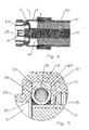
- Figure 4 is a schematic cross-section side view of a coaxial connector according to embodiments of the present invention, with a section of coaxial cable attached.
- Figure 5 is a close-up view of area B of Figure 4 .
- Figure 6 is a schematic cross-section view of a second alternative embodiment coaxial connector, with a section of coaxial cable attached.
- Figure 7 is a close-up view of area C of Figure 6 .
- Figure 8 is a schematic cross-section view of a third alternative embodiment coaxial connector, with a section of coaxial cable attached.
- Figure 9 is a close-up view of area D of Figure 8 .
- Figure 10 is a schematic cross-section view of a second alternative embodiment coaxial connector, with a section of coaxial cable attached.
- a coaxial connecter 1 according to 12/264,932 has a connector body 3 with a connector body bore 5.
- An insulator 7 seated within the connector body bore 5 supports an inner contact 9 coaxial with the connector body bore 5.
- the coaxial connector 1 mechanically retains the outer conductor 11 of a coaxial cable 13 inserted into the cable end 15 of the connector body bore 5 via a grip surface 17 located on the inner diameter of a grip ring 19, for example seated within a grip ring groove 27.
- a circular spring contact 21, such as a helical coil spring ring, seated within the connector body bore 5 makes circumferential contact with the outer conductor 11, electrically coupling the outer conductor 11 across the connector body 3 to a connector interface 23 at the connector end 25.
- the connector interface 23 may be any desired standard or proprietary interface.
- each individual element has a cable end 15 side and a connector end 25 side, i.e. the sides of the respective element that are facing the respective cable end 15 and the connector end 25 of the coaxial connector 1.
- a width of the contact groove 29 is typically dimensioned to receive the expected variance of spring contact 21 widths and to provide space for lateral deformation as the spring contact 21 is compressed/deformed between the groove bottom 31 and the outer conductor 11 during assembly.
- Primary mechanical retention of the connector 1 to the outer conductor 11 is separately provided, for example in the 12/264,932 embodiment by a directional grip ring 19 gripping the outer conductor 11 that prevents longitudinal removal of the coaxial cable 13 from the connector 1 once inserted, but that does not rigidly clamp the connector 1 to the outer conductor 11, thus enabling rotation there between.
- the inventor has recognized that, although a connector according to 12/264,932 enables rotation between the connector 1 and coaxial cable 13, such configurations may generate unacceptable levels of PIM, for example as less than uniform circumferential contact occurs between the spring contact 21 and one or more of the various surfaces of the contact groove 29 during assembly and/or upon post-assembly rotation between the coaxial cable 13 and the connector 1. It is believed that the presence of these multiple non-circumferentially uniform electrical paths between the spring contact 21 and the connector body 3 are contributors to the generation of PIM.
- primary and/or exclusive electrical contact between the spring contact 21 and the contact groove 29 is configured to occur along the connector end sidewall 33 of the contact groove 29.
- the coupling arrangement may be configured such that no contact is made between the spring contact 29 and the groove bottom 31, even in the deformed state(s) of the spring contact 21 resulting from assembly and/or rotation after assembly.
- the connector end sidewall 33 of the contact groove 29 may be angled or include transition features to transition between a groove bottom 31 width that is less than a groove top 35 width.
- the spring contact 21 has a non-deformed state width greater than the groove bottom 31 width and less than the groove top 35 width. At least while in a non-deformed state the spring contact 21 seats within the contact groove 29 contacting the connector end sidewall 33, without contacting the groove bottom 31.
- the connector end sidewall 33 may be planar between the groove bottom 31 and the groove top 35 (see Figure 9 ), or alternatively include a shoulder transition 39 against which the spring contact 21 seats.
- the shoulder transition 39 may be formed with a single corner, for example as demonstrated in Figures 4 and 5 , or alternatively with multiple corners and/or curves as demonstrated in Figures 6 and 7 .
- a bias gasket 41 may be provided in the contact groove 29, between the spring contact 21 and the cable end sidewall 37, for example as demonstrated in Figures 8-10 .
- the bias gasket 41 may be selected with elasticity characteristics and/or dimensioned to bias the spring contact 21 against the connector end sidewall 33, while the spring contact 21 is in the non-deformed state. In this configuration, once seated between the bias gasket 41 and the cable end sidewall 37, the bias gasket 41 provides an elastic gripping characteristic operative to engage and retain the spring contact 21 to inhibit further deformation of the spring contact 21 during rotation of the coaxial cable 13 with respect to the connector 1.
- the coupling arrangement according to the invention does not require a grip ring 19 type mechanical interconnection.
- One skilled in the art will appreciate that other types of mechanical interconnection that also enable rotation of the interconnection may be applied.
- the mechanical interconnection may be formed by providing a back nut 43 threadable onto the cable end 15 of the connector body 3 dimensioned to hold a retaining element proximate the cable end 15 of the connector body 3.
- the retaining element may be, for example, a plurality of arc inserts, a c-shaped ring, a retaining coil spring 45 or the like dimensioned to seat within a trough 47 of an annular corrugation of the outer conductor 11.
- the connector body 3 and back nut 43 together form an annular retaining groove 49.
- the retaining element is seated within the retaining groove 49, held captive in the selected trough 47 of the outer conductor 11, thereby longitudinally mechanically retaining the coaxial cable 13 within the connector body 3 but otherwise enabling rotation between the coaxial cable 13 and the connector 1.
- a coupling arrangement By ensuring a uniform circumferential primary contact surface along the shortest electrical path to the connection interface 23, a coupling arrangement according to the invention enables improved PIM characteristics for connectors with a rotatable interconnection characteristic.
Landscapes
- Coupling Device And Connection With Printed Circuit (AREA)
Abstract
A coupling arrangement between a coaxial connector body (3) and an outer conductor (11) of a coaxial cable (13) that includes an annular contact groove (29) provided in a bore (5) of the connector body (3). The contact groove (29) has a groove bottom (31), a connector end sidewall (33) and a cable end sidewall (37). The connector end sidewall (33) is angled to transition between a groove bottom (31) width that is less than a groove top (35) width. A spring contact (21) has a non-deformed state width seated within the contact groove (29). The non-deformed state width is greater than the groove bottom (31) width and less than the groove top (35) width. In a non-deformed state the spring contact (29) contacts the connector end sidewall (33), without contacting the groove bottom (31).
Description
- This invention relates to electrical cable connectors. More particularly, the invention relates to a solid outer conductor coaxial cable connector that is rotatable while mounted upon the cable end, which exhibits an improved passive intermodulation distortion (PIM) electrical performance.
- Coaxial cable connectors are used, for example, in communication systems requiring high levels of electrical performance, precision and reliability.
- To create a secure mechanical and optimized electrical interconnection between the cable and the connector, it is desirable to have generally uniform, circumferential contact between a leading edge of the coaxial cable outer conductor and the connector body. A flared end of the outer conductor may be clamped against an annular wedge surface of the connector body, via a coupling nut. Representative of this technology is commonly owned
US Patent No. 7335059 issued February 26, 2008 to Vaccaro . - During systems installation, rotational forces may be applied to the installed connector, for example as the attached coaxial cable is routed towards the next interconnection, maneuvered into position and/or curved for alignment with cable supports and/or retaining hangers. Rotation of the coaxial cable and a cable end clamping type coaxial connector with respect to each other may damage the connector, cable and/or the integrity of the cable/connector clamp inter-connection.
- Competition in the coaxial cable connector market has focused attention on improving electrical performance and minimization of overall costs, including materials costs, training requirements for installation personnel, reduction of dedicated installation tooling and the total number of required installation steps and/or operations.
- Therefore, it is an object of the invention to provide a connector that overcomes deficiencies in the prior art.
- The accompanying drawings, which are incorporated in and constitute a part of this specification, illustrate embodiments of the invention, where like reference numbers in the drawing figures refer to the same feature or element and may not be described in detail for every drawing figure in which they appear and, together with a general description of the invention given above, and the detailed description of the embodiments given below, serve to explain the principles of the invention.
-
Figure 1 is a schematic isometric rear view of an exemplary embodiment of a coaxial connector according toUS Patent Application serial number 12/264,932 . -
Figure 2 is a schematic cross-section side view of the coaxial connector ofFigure 1 , with a section of coaxial cable attached. -
Figure 3 is a close-up view of area A ofFigure 2 . -
Figure 4 is a schematic cross-section side view of a coaxial connector according to embodiments of the present invention, with a section of coaxial cable attached. -
Figure 5 is a close-up view of area B ofFigure 4 . -
Figure 6 is a schematic cross-section view of a second alternative embodiment coaxial connector, with a section of coaxial cable attached. -
Figure 7 is a close-up view of area C ofFigure 6 . -
Figure 8 is a schematic cross-section view of a third alternative embodiment coaxial connector, with a section of coaxial cable attached. -
Figure 9 is a close-up view of area D ofFigure 8 . -
Figure 10 is a schematic cross-section view of a second alternative embodiment coaxial connector, with a section of coaxial cable attached. - Commonly owned
US Patent Application serial number 12/264,932 - As shown in
Figures 1-3 , a coaxial connecter 1 according to12/264,932 connector body bore 5. An insulator 7 seated within the connector body bore 5 supports aninner contact 9 coaxial with theconnector body bore 5. The coaxial connector 1 mechanically retains theouter conductor 11 of acoaxial cable 13 inserted into thecable end 15 of the connector body bore 5 via agrip surface 17 located on the inner diameter of agrip ring 19, for example seated within agrip ring groove 27. Acircular spring contact 21, such as a helical coil spring ring, seated within theconnector body bore 5 makes circumferential contact with theouter conductor 11, electrically coupling theouter conductor 11 across the connector body 3 to aconnector interface 23 at theconnector end 25. Theconnector interface 23 may be any desired standard or proprietary interface. - One skilled in the art will appreciate that the
cable end 15 and theconnector end 25 are descriptors used herein to clarify longitudinal locations and contacting interrelationships between the various elements of the coaxial connector 1. In addition to the identified positions in relation to adjacent elements along the coaxial connector 1 longitudinal axis, each individual element has acable end 15 side and aconnector end 25 side, i.e. the sides of the respective element that are facing therespective cable end 15 and theconnector end 25 of the coaxial connector 1. - Electrical coupling between the
outer conductor 11 and the connector body 3 is provided by thespring contact 21 seated proximate a leading edge of theouter conductor 11. The seating area for thecircular spring contact 21, typically arectangular contact groove 29 formed in thebore 5 sidewall, is generally dimensioned shallow enough to force thespring contact 21 into secure contact with thegroove bottom 31 upon insertion of the leading edge of theouter conductor 11 into theconnector body bore 5. A width of thecontact groove 29 is typically dimensioned to receive the expected variance ofspring contact 21 widths and to provide space for lateral deformation as thespring contact 21 is compressed/deformed between thegroove bottom 31 and theouter conductor 11 during assembly. - Primary mechanical retention of the connector 1 to the
outer conductor 11 is separately provided, for example in the 12/264,932 embodiment by adirectional grip ring 19 gripping theouter conductor 11 that prevents longitudinal removal of thecoaxial cable 13 from the connector 1 once inserted, but that does not rigidly clamp the connector 1 to theouter conductor 11, thus enabling rotation there between. - The inventor has recognized that, although a connector according to 12/264,932 enables rotation between the connector 1 and
coaxial cable 13, such configurations may generate unacceptable levels of PIM, for example as less than uniform circumferential contact occurs between thespring contact 21 and one or more of the various surfaces of thecontact groove 29 during assembly and/or upon post-assembly rotation between thecoaxial cable 13 and the connector 1. It is believed that the presence of these multiple non-circumferentially uniform electrical paths between thespring contact 21 and the connector body 3 are contributors to the generation of PIM. - In a coupling arrangement according to the invention, primary and/or exclusive electrical contact between the
spring contact 21 and thecontact groove 29 is configured to occur along theconnector end sidewall 33 of thecontact groove 29. Thereby, any deformation of thespring contact 21 during assembly and/or post-assembly rotation may not create less than a uniform circumferential electrical interconnection along theconnector end sidewall 33 of thecontact groove 29. - Further, by configuring the depth and/or width of the
contact groove 29 with respect to the selectedspring contact 21 dimensions, the coupling arrangement may be configured such that no contact is made between thespring contact 29 and thegroove bottom 31, even in the deformed state(s) of thespring contact 21 resulting from assembly and/or rotation after assembly. - To provide a seating surface for the
spring contact 21, other than thegroove bottom 31, theconnector end sidewall 33 of thecontact groove 29 may be angled or include transition features to transition between agroove bottom 31 width that is less than agroove top 35 width. Thespring contact 21 has a non-deformed state width greater than thegroove bottom 31 width and less than thegroove top 35 width. At least while in a non-deformed state thespring contact 21 seats within thecontact groove 29 contacting theconnector end sidewall 33, without contacting thegroove bottom 31. - The
connector end sidewall 33 may be planar between thegroove bottom 31 and the groove top 35 (seeFigure 9 ), or alternatively include ashoulder transition 39 against which the spring contact 21 seats. Theshoulder transition 39 may be formed with a single corner, for example as demonstrated inFigures 4 and 5 , or alternatively with multiple corners and/or curves as demonstrated inFigures 6 and 7 . - In further embodiments, a
bias gasket 41 may be provided in thecontact groove 29, between thespring contact 21 and thecable end sidewall 37, for example as demonstrated inFigures 8-10 . Thebias gasket 41 may be selected with elasticity characteristics and/or dimensioned to bias thespring contact 21 against theconnector end sidewall 33, while thespring contact 21 is in the non-deformed state. In this configuration, once seated between thebias gasket 41 and thecable end sidewall 37, thebias gasket 41 provides an elastic gripping characteristic operative to engage and retain thespring contact 21 to inhibit further deformation of thespring contact 21 during rotation of thecoaxial cable 13 with respect to the connector 1. - The coupling arrangement according to the invention does not require a
grip ring 19 type mechanical interconnection. One skilled in the art will appreciate that other types of mechanical interconnection that also enable rotation of the interconnection may be applied. For example, as demonstrated inFigure 10 , where the connector 1 is configured for use withcoaxial cable 13 having an annular corrugatedouter conductor 11, the mechanical interconnection may be formed by providing aback nut 43 threadable onto thecable end 15 of the connector body 3 dimensioned to hold a retaining element proximate thecable end 15 of the connector body 3. The retaining element may be, for example, a plurality of arc inserts, a c-shaped ring, a retaining coil spring 45 or the like dimensioned to seat within a trough 47 of an annular corrugation of theouter conductor 11. When coupled together, the connector body 3 andback nut 43 together form an annular retaining groove 49. The retaining element is seated within the retaining groove 49, held captive in the selected trough 47 of theouter conductor 11, thereby longitudinally mechanically retaining thecoaxial cable 13 within the connector body 3 but otherwise enabling rotation between thecoaxial cable 13 and the connector 1. - By ensuring a uniform circumferential primary contact surface along the shortest electrical path to the
connection interface 23, a coupling arrangement according to the invention enables improved PIM characteristics for connectors with a rotatable interconnection characteristic.Table of Parts 1 coaxial connector 3 connector body 5 connector body bore 7 insulator 9 inner contact 11 outer conductor 13 coaxial cable 15 cable end 17 grip surface 19 grip ring 21 spring contact 23 connector interface 25 connector end 27 grip ring groove 29 contact groove 31 groove bottom 33 connector end sidewall 35 groove top 37 cable end sidewall 39 shoulder transition 41 bias gasket 43 back nut 45 retaining coil spring 47 trough 49 retaining groove - Where in the foregoing description reference has been made to materials, ratios, integers or components having known equivalents then such equivalents are herein incorporated as if individually set forth.
- While the present invention has been illustrated by the description of the embodiments thereof, and while the embodiments have been described in considerable detail, it is not the intention of the applicant to restrict or in any way limit the scope of the appended claims to such detail. Additional advantages and modifications will readily appear to those skilled in the art. Therefore, the invention in its broader aspects is not limited to the specific details, representative apparatus, methods, and illustrative examples shown and described. Accordingly, departures may be made from such details without departure from the spirit or scope of applicant's general inventive concept. Further, it is to be appreciated that improvements and/or modifications may be made thereto without departing from the scope or spirit of the present invention as defined by the following claims.
Claims (10)
- A coupling arrangement between a coaxial connector body and an outer conductor of a coaxial cable, comprising:an annular contact groove provided in a bore of the connector body; the contact groove having a groove bottom, a connector end sidewall and a cable end sidewall; the connector end sidewall angled to transition between a groove bottom width that is less than a groove top width;a circular spring contact having a non-deformed state width; the spring contact seated within the contact groove; the non-deformed state width greater than the groove bottom width and less than the groove top width; wherein in a non-deformed state the spring contact contacts the connector end sidewall without contacting the groove bottom.
- The coupling arrangement of claim 1, wherein the connector end sidewall is angled at a shoulder transition; the spring contact contacting the shoulder transition.
- The coupling arrangement of claim 1, further including an annular bias gasket in the contact groove between the spring contact and the cable end sidewall.
- The coupling arrangement of claim 1, further including a grip ring retained within a grip ring groove provided in the bore; an inner diameter of the grip ring provided with a grip surface; whereby the grip ring grips the outer conductor after the outer conductor is inserted through the grip ring.
- The coupling arrangement of claim 1, further including a back nut threadable onto a cable end of the connector body and a retaining element proximate the cable end of the connector body.
- The coupling arrangement of claim 5, wherein the retaining element is a retaining coil spring dimensioned to seat within an annular corrugation of the outer conductor.
- The coupling arrangement of claim 5, wherein the connector body and the back nut together form an annular retaining groove; the retaining element seated within the retaining groove.
- The coupling arrangement of claim 1, wherein the contact groove is located longitudinally on the connector body to position the spring contact proximate a leading edge of the outer conductor when the outer conductor is inserted within the connector bore.
- A coupling arrangement between a coaxial connector body and a solid outer conductor, comprising:a contact groove provided in a bore of the connector body; the contact groove having a groove bottom, a connector end sidewall and a cable end sidewall; the connector end sidewall angled to transition between a groove bottom width that is less than a groove top width;a spring contact having a non-deformed state width; the non-deformed state width greater than the groove bottom width and less than the groove top width; the circular spring contact seated within the annular groove;a back nut threadable onto the cable end of the connector body;a retaining coil spring dimensioned to seat within an annular corrugation of the outer conductor; the connector body and the back nut together forming an annular retaining groove; the retaining circular coil spring seated within the retaining groove.
- The coupling arrangement of claim 9, further including a bias gasket in the contact groove between the spring contact and the cable end sidewall; the bias gasket dimensioned to bias the spring contact against the connector end sidewall while in the spring contact is in the non-deformed state.
Applications Claiming Priority (1)
| Application Number | Priority Date | Filing Date | Title |
|---|---|---|---|
| US12/361,720 US7727013B1 (en) | 2009-01-29 | 2009-01-29 | Low PIM rotatable connector |
Publications (1)
| Publication Number | Publication Date |
|---|---|
| EP2214266A1 true EP2214266A1 (en) | 2010-08-04 |
Family
ID=42041716
Family Applications (1)
| Application Number | Title | Priority Date | Filing Date |
|---|---|---|---|
| EP10000574A Withdrawn EP2214266A1 (en) | 2009-01-29 | 2010-01-21 | Low PIM rotatable connector |
Country Status (3)
| Country | Link |
|---|---|
| US (1) | US7727013B1 (en) |
| EP (1) | EP2214266A1 (en) |
| CN (1) | CN101916926A (en) |
Cited By (1)
| Publication number | Priority date | Publication date | Assignee | Title |
|---|---|---|---|---|
| CN107104332A (en) * | 2017-03-23 | 2017-08-29 | 西安空间无线电技术研究所 | A kind of passive intermodulation suppresses coaxial connector |
Families Citing this family (20)
| Publication number | Priority date | Publication date | Assignee | Title |
|---|---|---|---|---|
| US8136234B2 (en) * | 2008-11-24 | 2012-03-20 | Andrew Llc | Flaring coaxial cable end preparation tool and associated methods |
| US7931499B2 (en) | 2009-01-28 | 2011-04-26 | Andrew Llc | Connector including flexible fingers and associated methods |
| US8157587B2 (en) * | 2010-06-07 | 2012-04-17 | Andrew Llc | Connector stabilizing coupling body assembly |
| CN101958492B (en) * | 2010-08-26 | 2015-07-22 | 杭州全盛机电科技有限公司 | High-frequency rotary connector |
| US8491333B2 (en) * | 2011-09-09 | 2013-07-23 | Ppc Broadband, Inc. | Rotary locking push-on connector and method thereof |
| US8968025B2 (en) | 2011-12-27 | 2015-03-03 | Glen David Shaw | Coupling continuity connector |
| US9039445B2 (en) | 2011-12-27 | 2015-05-26 | Perfectvision Manufacturing, Inc. | Body circuit connector |
| US8636541B2 (en) * | 2011-12-27 | 2014-01-28 | Perfectvision Manufacturing, Inc. | Enhanced coaxial connector continuity |
| US9793660B2 (en) * | 2012-03-19 | 2017-10-17 | Holland Electronics, Llc | Shielded coaxial connector |
| CN103311749B (en) * | 2013-05-15 | 2016-08-24 | 大唐移动通信设备有限公司 | A kind of radio frequency connector |
| ES2583636B1 (en) | 2015-03-20 | 2017-06-29 | Te Connectivity Amp España, S.L.U. | Connector with detachable link box |
| ES2584539B1 (en) * | 2015-03-27 | 2017-07-04 | Te Connectivity Amp España, S.L.U. | Connector set with grounding spring |
| ES2584540B1 (en) | 2015-03-27 | 2017-07-05 | Te Connectivity Amp España, S.L.U. | Latch for telecommunications connector |
| ES2584533B1 (en) | 2015-03-27 | 2017-08-04 | Te Connectivity Amp España, S.L.U. | Cover set for a telecommunications connector |
| US10651608B2 (en) | 2016-07-08 | 2020-05-12 | Commscope Technologies Llc | Connector assembly with grounding clamp system |
| CN113346289B (en) | 2016-08-15 | 2025-06-24 | 康普技术有限责任公司 | Connector assembly with grounding portion |
| WO2018236875A1 (en) | 2017-06-19 | 2018-12-27 | Commscope Technologies Llc | HIGH DENSITY DIAL FOR CONNECTION BOARD |
| US10079447B1 (en) * | 2017-07-21 | 2018-09-18 | Pct International, Inc. | Coaxial cable connector with an expandable pawl |
| EP3707915B1 (en) | 2017-11-10 | 2023-09-13 | Commscope Technologies LLC | Telecommunications panel with grounding wire |
| US11824293B2 (en) * | 2021-12-01 | 2023-11-21 | Hamilton Sundstrand Corporation | Circuit board with high power interconnect conductive coil |
Citations (5)
| Publication number | Priority date | Publication date | Assignee | Title |
|---|---|---|---|---|
| DE2133392A1 (en) | 1971-07-05 | 1973-01-18 | Spinner Georg | CABLE CONNECTOR FOR COAXIAL CABLE |
| US3739076A (en) | 1972-04-17 | 1973-06-12 | L Schwartz | Electrical cable terminating and grounding connector |
| US4824400A (en) | 1987-03-13 | 1989-04-25 | Georg Spinner | Connector for a coaxial line with corrugated outer conductor or a corrugated waveguide tube |
| EP0798815A2 (en) | 1996-03-28 | 1997-10-01 | Andrew A.G. | Connector assembly for a coaxial cable having a corrugated outer conductor |
| US7335059B2 (en) | 2006-03-08 | 2008-02-26 | Commscope, Inc. Of North Carolina | Coaxial connector including clamping ramps and associated method |
Family Cites Families (3)
| Publication number | Priority date | Publication date | Assignee | Title |
|---|---|---|---|---|
| US4213664A (en) * | 1978-10-11 | 1980-07-22 | Mcclenan Warren G | Visually inspectable grounding connector for electrical cable |
| SE510051C2 (en) | 1998-02-17 | 1999-04-12 | Teracom Components Ab | Contact device for high frequency cables |
| US6793529B1 (en) | 2003-09-30 | 2004-09-21 | Andrew Corporation | Coaxial connector with positive stop clamping nut attachment |
-
2009
- 2009-01-29 US US12/361,720 patent/US7727013B1/en active Active
-
2010
- 2010-01-21 EP EP10000574A patent/EP2214266A1/en not_active Withdrawn
- 2010-01-29 CN CN2010101485406A patent/CN101916926A/en active Pending
Patent Citations (5)
| Publication number | Priority date | Publication date | Assignee | Title |
|---|---|---|---|---|
| DE2133392A1 (en) | 1971-07-05 | 1973-01-18 | Spinner Georg | CABLE CONNECTOR FOR COAXIAL CABLE |
| US3739076A (en) | 1972-04-17 | 1973-06-12 | L Schwartz | Electrical cable terminating and grounding connector |
| US4824400A (en) | 1987-03-13 | 1989-04-25 | Georg Spinner | Connector for a coaxial line with corrugated outer conductor or a corrugated waveguide tube |
| EP0798815A2 (en) | 1996-03-28 | 1997-10-01 | Andrew A.G. | Connector assembly for a coaxial cable having a corrugated outer conductor |
| US7335059B2 (en) | 2006-03-08 | 2008-02-26 | Commscope, Inc. Of North Carolina | Coaxial connector including clamping ramps and associated method |
Cited By (2)
| Publication number | Priority date | Publication date | Assignee | Title |
|---|---|---|---|---|
| CN107104332A (en) * | 2017-03-23 | 2017-08-29 | 西安空间无线电技术研究所 | A kind of passive intermodulation suppresses coaxial connector |
| CN107104332B (en) * | 2017-03-23 | 2019-07-12 | 西安空间无线电技术研究所 | A kind of passive intermodulation inhibition coaxial connector |
Also Published As
| Publication number | Publication date |
|---|---|
| CN101916926A (en) | 2010-12-15 |
| US7727013B1 (en) | 2010-06-01 |
Similar Documents
| Publication | Publication Date | Title |
|---|---|---|
| US7727013B1 (en) | Low PIM rotatable connector | |
| JP7410869B2 (en) | gang type coax connector assembly | |
| CN107735910B (en) | Coax connector interface used to prevent mating with incorrect connectors | |
| US7824214B2 (en) | Coupling nut with cable jacket retention | |
| US7753727B1 (en) | Threaded crimp coaxial connector | |
| US8801460B2 (en) | RF shielded capacitively coupled connector | |
| EP1956687A2 (en) | Annular corrugated coaxial cable connector with polymeric spring finger nut | |
| US8002580B2 (en) | Coaxial cable crimp connector | |
| EP2451020B1 (en) | RF module | |
| US7448906B1 (en) | Hollow inner conductor contact for coaxial cable connector | |
| US8029324B1 (en) | RF connector assembly | |
| EP2214265A1 (en) | Inner contact supporting and biasing insulator | |
| EP3167512B1 (en) | Electrical connector for high-speed transmission using twisted-pair cable | |
| EP2184814A1 (en) | Axial compression connector | |
| US20100233903A1 (en) | Inner conductor end contacting coaxial connector and inner conductor adapter kit | |
| US20070224880A1 (en) | Axial Compression Electrical Connector for Annular Corrugated Coaxial Cable | |
| EP2149934A1 (en) | Coaxial connector inner contact arrangement | |
| EP2281329A2 (en) | Anti-rotation coaxial connector | |
| CN102971921A (en) | Coaxial connector with inhibited ingress and improved grounding | |
| US8888528B2 (en) | Dual connector interface for capacitive or conductive coupling | |
| US7736180B1 (en) | Inner conductor wedge attachment coupling coaxial connector | |
| WO2014074223A1 (en) | Rf isolated capacitively coupled connector | |
| US20160285205A1 (en) | Connector assembly with grounding spring | |
| EP2497155A1 (en) | Interleaved outer conductor shield contact | |
| US9960527B2 (en) | Electrical assembly having a backshell with a cable follower |
Legal Events
| Date | Code | Title | Description |
|---|---|---|---|
| PUAI | Public reference made under article 153(3) epc to a published international application that has entered the european phase |
Free format text: ORIGINAL CODE: 0009012 |
|
| AK | Designated contracting states |
Kind code of ref document: A1 Designated state(s): AT BE BG CH CY CZ DE DK EE ES FI FR GB GR HR HU IE IS IT LI LT LU LV MC MK MT NL NO PL PT RO SE SI SK SM TR |
|
| AX | Request for extension of the european patent |
Extension state: AL BA RS |
|
| 17P | Request for examination filed |
Effective date: 20101118 |
|
| 17Q | First examination report despatched |
Effective date: 20110201 |
|
| STAA | Information on the status of an ep patent application or granted ep patent |
Free format text: STATUS: THE APPLICATION IS DEEMED TO BE WITHDRAWN |
|
| 18D | Application deemed to be withdrawn |
Effective date: 20130801 |