EP2214261A1 - Beam forming antenna system on flexible plastic foil - Google Patents
Beam forming antenna system on flexible plastic foil Download PDFInfo
- Publication number
- EP2214261A1 EP2214261A1 EP09290073A EP09290073A EP2214261A1 EP 2214261 A1 EP2214261 A1 EP 2214261A1 EP 09290073 A EP09290073 A EP 09290073A EP 09290073 A EP09290073 A EP 09290073A EP 2214261 A1 EP2214261 A1 EP 2214261A1
- Authority
- EP
- European Patent Office
- Prior art keywords
- antenna
- signal processing
- processing units
- antenna system
- antenna elements
- Prior art date
- Legal status (The legal status is an assumption and is not a legal conclusion. Google has not performed a legal analysis and makes no representation as to the accuracy of the status listed.)
- Withdrawn
Links
- 239000011888 foil Substances 0.000 title claims abstract description 18
- 229920002457 flexible plastic Polymers 0.000 title claims abstract description 16
- 239000000758 substrate Substances 0.000 claims abstract description 35
- 238000007639 printing Methods 0.000 claims description 6
- 230000007613 environmental effect Effects 0.000 claims description 2
- 238000004891 communication Methods 0.000 description 6
- 230000008054 signal transmission Effects 0.000 description 6
- 238000005516 engineering process Methods 0.000 description 5
- 238000003491 array Methods 0.000 description 4
- 239000000446 fuel Substances 0.000 description 3
- 238000000034 method Methods 0.000 description 3
- RYGMFSIKBFXOCR-UHFFFAOYSA-N Copper Chemical compound [Cu] RYGMFSIKBFXOCR-UHFFFAOYSA-N 0.000 description 2
- 239000010949 copper Substances 0.000 description 2
- 229910052802 copper Inorganic materials 0.000 description 2
- 239000004744 fabric Substances 0.000 description 2
- 239000013307 optical fiber Substances 0.000 description 2
- 229920003023 plastic Polymers 0.000 description 2
- 230000006978 adaptation Effects 0.000 description 1
- 238000010276 construction Methods 0.000 description 1
- 238000011161 development Methods 0.000 description 1
- 230000018109 developmental process Effects 0.000 description 1
- 239000000463 material Substances 0.000 description 1
- 238000010248 power generation Methods 0.000 description 1
Images

Classifications
-
- H—ELECTRICITY
- H01—ELECTRIC ELEMENTS
- H01Q—ANTENNAS, i.e. RADIO AERIALS
- H01Q21/00—Antenna arrays or systems
- H01Q21/28—Combinations of substantially independent non-interacting antenna units or systems
-
- H—ELECTRICITY
- H01—ELECTRIC ELEMENTS
- H01Q—ANTENNAS, i.e. RADIO AERIALS
- H01Q1/00—Details of, or arrangements associated with, antennas
- H01Q1/12—Supports; Mounting means
- H01Q1/1292—Supports; Mounting means for mounting on balloons
-
- H—ELECTRICITY
- H01—ELECTRIC ELEMENTS
- H01Q—ANTENNAS, i.e. RADIO AERIALS
- H01Q21/00—Antenna arrays or systems
- H01Q21/06—Arrays of individually energised antenna units similarly polarised and spaced apart
- H01Q21/061—Two dimensional planar arrays
-
- H—ELECTRICITY
- H01—ELECTRIC ELEMENTS
- H01Q—ANTENNAS, i.e. RADIO AERIALS
- H01Q23/00—Antennas with active circuits or circuit elements integrated within them or attached to them
Definitions
- This invention relates to beam forming antenna systems.
- the invention provides an antenna system comprising an antenna array having a plurality of arrayed antenna elements and a plurality of signal processing units respectively associated to said antenna elements and adapted for at least amplifying signals being fed from and/or to said respectively associated antenna elements, wherein said plurality of antenna elements and said associated signal processing units are commonly arranged on a flat supporting substrate which has flexibility and electric insulating property.
- the object of the present invention is creating a simple and easy-to-handle antenna system being suitable for two-dimensional antenna arrays and allowing a flexible structure for various applications and deployment scenarios.
- the antenna system according to the invention is an array antenna having a flexible flat supporting substrate that carries the antenna elements and the processing units.
- the antenna system of the present invention can be realized by printing the antenna elements and the processing units on a flexible plastic foil forming that supporting substrate.
- the present antenna system preferably forms a two-dimensional array, wherein the antenna elements are distributed vertically and horizontally on the flat and supporting substrate. In cases where the two-dimensional antenna array is bent or gets a three-dimensional shape depending on its application, the present antenna system has a third dimension in space.
- Each antenna element preferably can be controlled individually thus allowing e.g. beam forming or spatial multiplexing exploiting elevation and azimuth direction.
- the present antenna system can be realized by applying the antenna elements and even the signal processing units, e.g. by printing, on a flexible plastic foil which may be inflatable to become a balloon-like antenna object thus having a three-dimensional shape.
- the balloon-like antenna object may thus become a flying antenna object if inflated by a light gas.
- the inflated status of the inflatable flexible (elastically deformable) plastic foil may determine the respective frequency range of the antenna elements and/or the processing units of the balloon-like antenna object.
- Signal processing for the present antenna system can be carried out at least partly by the processing units respectively associated to the antenna elements and provided and arranged on the flat flexible supporting substrate.
- Signal processing of the present antenna system can also be carried out by means of a separate base station which may be provided at the exterior of the antenna array.
- the signal processing adapts to the actual size and/or shape of the antenna array resulting from the application and adapts to the antenna deployment and/or operation.
- the amount of the plurality of arrayed antenna elements and the plurality of signal processing units gives redundancy. Thus, if a single antenna element or processing unit is not functional, there are enough antenna elements and processing units in total remaining to be used from the signal processing entity. This concept allows various forms and sizes of the antenna array which also allows large antenna apertures. Flexible and thin antenna arrays according to the present invention can be easily and quickly deployed by just sticking them on objects where they are needed:
- the present antenna system may be applied to an air borne vehicle such as Zeppelin-like object or a balloon or also to a marine vehicle or to a marine-based beacon.
- the present antenna system may be applied to a stationary object, such as a building, an industrial facility, a power plant, a tower, a mast, a chimney, or a beacon.
- the present antenna system may be applied to a portable object, such as a cloth, a hat, a helmet, a portable telephone, a portable or movable radio transceiver and the like.
- at least the antenna elements and the signal processing units are applied by printing on said supporting substrate.
- the deployed antenna array on the flexible plastic foil can have any sort of bends and shapes depending on the object it is attached to or depending on the inflated status of the balloon-like antenna object. Therefore, as mentioned above, a signal processing adapts to the actual array shape and/or size of the array resulting at deployment and/or usage. Further, as mentioned above, a frequency range of said inflatable antenna object can be determined by the size or inflated status thereof.
- the antenna array including the antenna elements and the processing units can be linked to a base station partly carrying out the processing functions of the present antenna system.
- the link can be carried out by various technologies such as:
- the present antenna system can be arranged in combination with thin batteries, solar cells, fuel cells, etc., wherein thin batteries may also be applied and arranged on the flexible flat supporting substrate.
- the present antenna system having the above advantageous features thus allows complete new deployment scenarios in mobile wireless communication systems, adding more flexibility, allowing improved public acceptance by avoiding classical antenna shapes and by creating signal processing concepts. Further the present antenna system provides a low cost and very flexible new technology option.
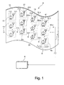
- the first embodiment of the invention as depicted in Fig.1 and described in the following description relates to an antenna system A comprising an antenna array having a plurality of arrayed antenna elements and a plurality of signal processing units respectively associated to said antenna elements and adapted for at least amplifying signals being fed from/or to said respectively associated antenna elements, wherein said plurality of antenna elements and said associated signal processing units are commonly arranged on a flat supporting substrate which has flexibility and electric insulating property.
- How to apply the present antenna system according to this invention to a variety of exemplary applications is schematically depicted in Figs. 2 to 7 and will be described in the following description.
- the antenna system A comprises an antenna array 11, 12, Vietnamese, 1l, 21, 22, ....,3n, 41, 42, ....4o having a plurality of two-dimensionally arrayed antenna elements only a part of which are designated by reference numbers 111, 211, 311, 411 and further a plurality of two-dimensionally arrayed signal processing units simply and schematically depicted as transistor symbols and only partly designated by reference numbers 112, 212, 312, 412.
- Signal processing units 112, 212, 312, 412 are respectively associated to a respective antenna element 111, 211, 311, 411 and adapted for at least amplifying signals being fed from/or to the associated antenna elements 111, 211, 311, 411.
- Signal transmission means 6, e.g. signal transmission lines are likewise arranged on the flexible substrate 10 for transmitting signals to/from the antenna elements 111, 211, 311, 411 and/or to/from the processing units 112, 212, 312, 412.
- the flat flexible supporting substrate 10 can have any sort of bends and shapes depending on an object to which it is attached or depending on a specific application of the present antenna system A.
- the processing units have an amplifying function, however, may additionally have certain other processing functions for the signals being fed from and/or to the respectively associated antenna elements.
- FIG. 1 shows that the processing units 112, 212, 312, 412 are also locally associated to the respective antenna element 111, 211, 311, 411, but alternatively the processing units 112, 212, 312, 412 may locally be concentrated at different sites on the flat flexible supporting substrate 10 even if these processing units are operatively one-to-one associated to the respective antenna elements 111, 211, 311, 411.
- the signal processing adapts to the actual array shape and /or size of the antenna array.
- Fig. 1 further depicts that in addition to the plurality of signal processing units 112, 212, 312, 412 the present antenna system may comprise a base station 8 provided in the exterior of the antenna array, i.e. the base station 8 is not arranged on the flexible flat supporting substrate 10 but linked to the plurality of signal processing units and/or the antenna elements on the flat flexible supporting substrate 10 by means of a signal communication link 7.
- This signal communication link 7 can be realized in various technologies, such as micro-wave link, free space optics (diffused or directed), in-band techniques (relaying, etc.), cable (copper or optical fiber).
- the latter may be combined with any possible power generation means such as thin batteries, solar cells, fuel cells, etc.
- Fig. 1 indicates that a solar cell battery 9 or alternatively a thin battery 9 can be arranged and fixed directly on the flat flexible supporting substrate 10.
- the plurality of antenna elements 111, 211, 311, 411 and associated signal processing units 112, 212, 312, 412 can be arranged with redundancy on the flexible supporting substrate 10. If a single antenna element and/or processing unit is not functional, the amount of redundant antenna elements and/or signal processing units can be used to maintain the functionality of the antenna system A.
- the present concept of the inventive antenna system A allows to individually control the plurality of antenna elements 111, 211, 311, 411 by the associated signal processing units 112, 212, 312, 412 and/or by the base station 8.
- the individual control of each antenna element allows to adapt the antenna system to at least one of the actual shape of the antenna array, the actual size thereof and to the number of antenna elements actually being in operation.
- each single antenna element by the associated processing unit allows beam forming or spatial multiplexing exploiting elevation and azimuth direction.
- the signal processing functionality beyond the amplifying function can be located partly or fully directly on the flexible flat supporting substrate 10 or it can be fully or partly implemented at the base station 8. Accordingly, the signal processing functionality can be located at both the flexible flat supporting substrate 10 and in the base station 8. I.e. the whole processing function (besides the amplifying functions carried out by the processing units 112, 212, 312, 412 of the antenna array) may be totally or partly implemented in the base station 8. Signal processing functions can be provided for signals fed from the signal processing units to the base station 8 and/or signals to be supplied from the base station 8 to the signal processing units 112, 212, 312, 412.
- the functionality of altering the antenna characteristic of the antenna system A in response to a corresponding control signal being for example supplied from the exterior to the antenna system A can be either partly or totally carried out by the base station 8 instead of being carried out by the signal processing units 112, 212, 312, 412 on the flexible flat supporting substrate 10.
- the flexible supporting substrate 10 depicted in Fig. 1 comprises a plastic foil.
- This allows to apply at least the antenna elements 111, 211, 311, 411, signal processing units 112, 212, 312, 412 and signal transmission lines 6 by a printing process on the flexible plastic foil 10 used as the flat flexible supporting substrate.
- the base station 8 can be totally or partly be printed on the flexible plastic foil 10 instead of being installed at the exterior of the flexible plastic foil 10 like it is described for the antenna system of the first embodiment as shown in Fig. 1 .
- a flexible protecting layer (not shown) can be applied on the flexible plastic foil 10 and adapted for covering and protecting at least the antenna elements 111, 211, 311, 411, the signal processing units 112, 212, 312, 412 and the signal transmission lines 6 on said flexible plastic foil 10 against harmful environmental interference.
- the first embodiment of the antenna system A of the present invention described above with reference to Fig. 1 forms a basis for complete new deployment scenarios in mobile wireless communication systems, adds more flexibility, allows improved public acceptance by avoiding classical antenna shapes and creates new signal processing concepts. Further the embodiment of the present antenna system A described above achieves a low cost flexible technology option.
- FIG. 2 An exemplary second embodiment depicted in Fig. 2 shows the antenna system A according to the present invention applied to an air borne flying object F, in the example a propelled Zeppelin.
- the flexible flat supporting substrate 10 carying the antenna elements, the signal processing units and the signal transmission lines as depicted in Fig. 1 is used to create an inflatable flying antenna object such as a balloon (unpropelled) where optionally the flexible supporting substrate 10 itself may be inflatabe.
- signal processing is either located at the antenna array applied to the flying object, at a base station linked by a communication link to the antenna array or at both, the base station and the antenna array.
- a size of the balloon, in particular an inflated status of the inflatable flexible plastic foil may determine the respective frequency range of the antenna elements and/or the processing units of the balloon-like antenna object.
- the flying antenna system A of the invention can be used for e.g. quickly setting up wireless communication, broadcast or surveillance networks at events with many users such as sport events.
- the flying antenna system A can be linked to a base station via various technology options mentioned above.
- combination with thin batteries, solar cells, fuel cells, etc. are preferred.
- the flying object carrying the antenna system A of the present invention is propelled by an engine such as the propelled Zeppelin according to Fig.2 , some power from the engine can also be used for the power supply of the electronics of the signal processing, or the engine even is a full power supply for a full base station carried onboard a flying object carrying the present antenna system A.
- a third exemplary embodiment is schematically depicted in Fig. 3 where the antenna system A of the present invention is applied to a ground vehicle V exemplified as a motor-driven bus.
- the antenna system A of the invention can be applied inside a bus, inside trains, etc. and further on different vehicles like private cars, police cars, firefighter cars, military vehicles, etc.
- the antenna system A according to the present invention can be applied at a marine vehicle, such as a ship or ferry.
- FIG. 4 A fourth exemplary embodiment is depicted in Fig. 4 where the antenna system A according to the present invention is applied to a marine beacon B.
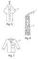
- Figs. 5 and 6 respectively show a fifth and sixth embodiment where the antenna system A is applied to a tower T and to a chimney K, respectively.
- the antenna system A of the present invention is integrated in an article of dress D, in the example a coat.
Landscapes
- Variable-Direction Aerials And Aerial Arrays (AREA)
- Details Of Aerials (AREA)
Abstract
Description
- This invention relates to beam forming antenna systems.
- Existing conventional antenna arrays which allow beam forming are made of rigid non-flexible materials and therefore are difficult to handle and not easily adaptable on different antenna applications and/or operations. Further, the known beam forming antenna systems are mostly very expensive and need heavy and non-flexible supporting constructions.
- According to an important aspect the invention provides an antenna system comprising an antenna array having a plurality of arrayed antenna elements and a plurality of signal processing units respectively associated to said antenna elements and adapted for at least amplifying signals being fed from and/or to said respectively associated antenna elements, wherein said plurality of antenna elements and said associated signal processing units are commonly arranged on a flat supporting substrate which has flexibility and electric insulating property.
- In view of the above the object of the present invention is creating a simple and easy-to-handle antenna system being suitable for two-dimensional antenna arrays and allowing a flexible structure for various applications and deployment scenarios.
- Thus, the antenna system according to the invention is an array antenna having a flexible flat supporting substrate that carries the antenna elements and the processing units.
- According to advantageous developments, the antenna system of the present invention can be realized by printing the antenna elements and the processing units on a flexible plastic foil forming that supporting substrate.
- The present antenna system preferably forms a two-dimensional array, wherein the antenna elements are distributed vertically and horizontally on the flat and supporting substrate. In cases where the two-dimensional antenna array is bent or gets a three-dimensional shape depending on its application, the present antenna system has a third dimension in space. Each antenna element preferably can be controlled individually thus allowing e.g. beam forming or spatial multiplexing exploiting elevation and azimuth direction.
- The present antenna system can be realized by applying the antenna elements and even the signal processing units, e.g. by printing, on a flexible plastic foil which may be inflatable to become a balloon-like antenna object thus having a three-dimensional shape. The balloon-like antenna object may thus become a flying antenna object if inflated by a light gas. Thereby, the inflated status of the inflatable flexible (elastically deformable) plastic foil may determine the respective frequency range of the antenna elements and/or the processing units of the balloon-like antenna object.
- Signal processing for the present antenna system can be carried out at least partly by the processing units respectively associated to the antenna elements and provided and arranged on the flat flexible supporting substrate.
- Signal processing of the present antenna system can also be carried out by means of a separate base station which may be provided at the exterior of the antenna array. Preferably the signal processing adapts to the actual size and/or shape of the antenna array resulting from the application and adapts to the antenna deployment and/or operation.
- The amount of the plurality of arrayed antenna elements and the plurality of signal processing units gives redundancy. Thus, if a single antenna element or processing unit is not functional, there are enough antenna elements and processing units in total remaining to be used from the signal processing entity. This concept allows various forms and sizes of the antenna array which also allows large antenna apertures. Flexible and thin antenna arrays according to the present invention can be easily and quickly deployed by just sticking them on objects where they are needed:
- around and on street lamps, buildings, chimneys, towers;
- on vehicles such as private cars, police vehicles, firefighter vehicles, military vehicles, etc.;
- inside e.g. of busses, trains or at the exterior walls thereof;
- in industrial plants, on machines, etc.;
- it is further possible to form a balloon-like flying antenna object or to apply the present antenna system on clothes, hats, helmets, etc.
- According to a second preferred application, the present antenna system may be applied to an air borne vehicle such as Zeppelin-like object or a balloon or also to a marine vehicle or to a marine-based beacon. According to a further advantageous application the present antenna system may be applied to a stationary object, such as a building, an industrial facility, a power plant, a tower, a mast, a chimney, or a beacon. Moreover, according to another advantageous application, the present antenna system may be applied to a portable object, such as a cloth, a hat, a helmet, a portable telephone, a portable or movable radio transceiver and the like. Preferably, in all of these applications, at least the antenna elements and the signal processing units are applied by printing on said supporting substrate.
- The deployed antenna array on the flexible plastic foil can have any sort of bends and shapes depending on the object it is attached to or depending on the inflated status of the balloon-like antenna object. Therefore, as mentioned above, a signal processing adapts to the actual array shape and/or size of the array resulting at deployment and/or usage. Further, as mentioned above, a frequency range of said inflatable antenna object can be determined by the size or inflated status thereof.
- Advantageously the antenna array including the antenna elements and the processing units can be linked to a base station partly carrying out the processing functions of the present antenna system. The link can be carried out by various technologies such as:
- micro-wave link;
- free-space optics (diffused or directed);
- in-band techniques (relaying, ...);
- cable (copper or optical fiber).
- For autonomous operation the present antenna system can be arranged in combination with thin batteries, solar cells, fuel cells, etc., wherein thin batteries may also be applied and arranged on the flexible flat supporting substrate.
- The present antenna system having the above advantageous features thus allows complete new deployment scenarios in mobile wireless communication systems, adding more flexibility, allowing improved public acceptance by avoiding classical antenna shapes and by creating signal processing concepts. Further the present antenna system provides a low cost and very flexible new technology option.
- Various exemplary embodiments of the inventive antenna system will be described in detail with reference to the following figures, wherein:
- Fig. 1
- schematically depicts a first embodiment of the antenna system of the present invention wherein antenna elements and processing units are two-dimensionally distributed and arranged on a flexible flat supporting substrate;
- Figs. 2 to 7
- are schematically depicting further different exemplary embodiments of the invention, where the present antenna system is applied to various different supporting objects, a Zeppelin, a bus, a beacon, a tower, a chimney, a cloth, respectively.
- The first embodiment of the invention as depicted in
Fig.1 and described in the following description relates to an antenna system A comprising an antenna array having a plurality of arrayed antenna elements and a plurality of signal processing units respectively associated to said antenna elements and adapted for at least amplifying signals being fed from/or to said respectively associated antenna elements, wherein said plurality of antenna elements and said associated signal processing units are commonly arranged on a flat supporting substrate which has flexibility and electric insulating property. How to apply the present antenna system according to this invention to a variety of exemplary applications is schematically depicted inFigs. 2 to 7 and will be described in the following description. - In the first embodiment of an antenna system A according to the invention as schematically shown in
Fig. 1 , the antenna system A comprises anantenna array reference numbers reference numbers signal processing units respective antenna element antenna elements flexible substrate 10 for transmitting signals to/from theantenna elements processing units - The flat flexible supporting
substrate 10 can have any sort of bends and shapes depending on an object to which it is attached or depending on a specific application of the present antenna system A. - The processing units have an amplifying function, however, may additionally have certain other processing functions for the signals being fed from and/or to the respectively associated antenna elements.
- Even if
Fig. 1 shows that theprocessing units respective antenna element processing units substrate 10 even if these processing units are operatively one-to-one associated to therespective antenna elements - In any case in the present antenna system the signal processing adapts to the actual array shape and /or size of the antenna array.
-
Fig. 1 further depicts that in addition to the plurality ofsignal processing units base station 8 provided in the exterior of the antenna array, i.e. thebase station 8 is not arranged on the flexible flat supportingsubstrate 10 but linked to the plurality of signal processing units and/or the antenna elements on the flat flexible supportingsubstrate 10 by means of asignal communication link 7. Thissignal communication link 7 can be realized in various technologies, such as micro-wave link, free space optics (diffused or directed), in-band techniques (relaying, etc.), cable (copper or optical fiber). For autonomous operation of the antenna system A the latter may be combined with any possible power generation means such as thin batteries, solar cells, fuel cells, etc.Fig. 1 indicates that asolar cell battery 9 or alternatively athin battery 9 can be arranged and fixed directly on the flat flexible supportingsubstrate 10. - According to the embodiment of the antenna system A depicted in
Fig. 1 , the plurality ofantenna elements signal processing units substrate 10. If a single antenna element and/or processing unit is not functional, the amount of redundant antenna elements and/or signal processing units can be used to maintain the functionality of the antenna system A. - The present concept of the inventive antenna system A allows to individually control the plurality of
antenna elements signal processing units base station 8. Thus the individual control of each antenna element allows to adapt the antenna system to at least one of the actual shape of the antenna array, the actual size thereof and to the number of antenna elements actually being in operation. - Further the concept of the individual control of each single antenna element by the associated processing unit allows beam forming or spatial multiplexing exploiting elevation and azimuth direction.
- As already mentioned, the signal processing functionality beyond the amplifying function can be located partly or fully directly on the flexible flat supporting
substrate 10 or it can be fully or partly implemented at thebase station 8. Accordingly, the signal processing functionality can be located at both the flexible flat supportingsubstrate 10 and in thebase station 8. I.e. the whole processing function (besides the amplifying functions carried out by theprocessing units base station 8. Signal processing functions can be provided for signals fed from the signal processing units to thebase station 8 and/or signals to be supplied from thebase station 8 to thesignal processing units signal processing units substrate 10 can be either partly or totally be carried out in thebase station 8. - Likewise the functionality of altering the antenna characteristic of the antenna system A in response to a corresponding control signal being for example supplied from the exterior to the antenna system A can be either partly or totally carried out by the
base station 8 instead of being carried out by thesignal processing units substrate 10. - Preferably and advantageously the flexible supporting
substrate 10 depicted inFig. 1 comprises a plastic foil. This allows to apply at least theantenna elements signal processing units signal transmission lines 6 by a printing process on theflexible plastic foil 10 used as the flat flexible supporting substrate. - Additionally also the
base station 8 can be totally or partly be printed on theflexible plastic foil 10 instead of being installed at the exterior of theflexible plastic foil 10 like it is described for the antenna system of the first embodiment as shown inFig. 1 . - In case of the embodiment mentioned above, wherein at least the
antenna elements signal processing units signal transmission lines 6 are applied by printing on theflexible plastic foil 10, a flexible protecting layer (not shown) can be applied on theflexible plastic foil 10 and adapted for covering and protecting at least theantenna elements signal processing units signal transmission lines 6 on saidflexible plastic foil 10 against harmful environmental interference. - The first embodiment of the antenna system A of the present invention described above with reference to
Fig. 1 forms a basis for complete new deployment scenarios in mobile wireless communication systems, adds more flexibility, allows improved public acceptance by avoiding classical antenna shapes and creates new signal processing concepts. Further the embodiment of the present antenna system A described above achieves a low cost flexible technology option. - An exemplary second embodiment depicted in
Fig. 2 shows the antenna system A according to the present invention applied to an air borne flying object F, in the example a propelled Zeppelin. - According to a further embodiment (not shown) the flexible flat supporting
substrate 10 carying the antenna elements, the signal processing units and the signal transmission lines as depicted inFig. 1 is used to create an inflatable flying antenna object such as a balloon (unpropelled) where optionally the flexible supportingsubstrate 10 itself may be inflatabe. Again in the embodiment depicted inFig. 2 and in the embodiment where the antenna system A is applied to a balloon, signal processing is either located at the antenna array applied to the flying object, at a base station linked by a communication link to the antenna array or at both, the base station and the antenna array. - If the present antenna system is realized as a balloon-like flying antenna object, a size of the balloon, in particular an inflated status of the inflatable flexible plastic foil may determine the respective frequency range of the antenna elements and/or the processing units of the balloon-like antenna object.
- In such cases where the antenna system A according to the present invention is applied to a flying object like the Zeppelin shown in
Fig. 2 or to an inflatable balloon, the flying antenna system A of the invention can be used for e.g. quickly setting up wireless communication, broadcast or surveillance networks at events with many users such as sport events. For these embodiments the flying antenna system A can be linked to a base station via various technology options mentioned above. As previously described for autonomous operation of the antenna system A of the present invention combination with thin batteries, solar cells, fuel cells, etc. are preferred. If the flying object carrying the antenna system A of the present invention is propelled by an engine such as the propelled Zeppelin according toFig.2 , some power from the engine can also be used for the power supply of the electronics of the signal processing, or the engine even is a full power supply for a full base station carried onboard a flying object carrying the present antenna system A. - A third exemplary embodiment is schematically depicted in
Fig. 3 where the antenna system A of the present invention is applied to a ground vehicle V exemplified as a motor-driven bus. - In other similar embodiments (not shown) the antenna system A of the invention can be applied inside a bus, inside trains, etc. and further on different vehicles like private cars, police cars, firefighter cars, military vehicles, etc.
- In a further embodiment (not shown) the antenna system A according to the present invention can be applied at a marine vehicle, such as a ship or ferry.
- A fourth exemplary embodiment is depicted in
Fig. 4 where the antenna system A according to the present invention is applied to a marine beacon B. -
Figs. 5 and 6 respectively show a fifth and sixth embodiment where the antenna system A is applied to a tower T and to a chimney K, respectively. - According to a seventh exemplary embodiment depicted in
Fig. 7 , the antenna system A of the present invention is integrated in an article of dress D, in the example a coat. - All embodiments described above and shown in the accompanying
Figs. 1 to 7 are realizing an antenna system allowing various flexible forms and sizes which also allows large antenna apertures. The flexible and thin antenna arrays according to the present invention can be easily and quickly deployed by just sticking them where they are needed: - around and on street lamps, buildings, towers, chimneys, etc., on vehicles (air borne, land borne and marine borne vehicles, private cars, police cars, firefighter vehicles, military vehicles, etc.), inside busses, trains, subways, etc., in industrial plants, on machines,
- as a flying balloon-like antenna object, and
- further the flexible thin antenna array according to the present invention can be integrated in clothes, such as depicted in
Fig. 7 .
Claims (15)
- An antenna system (A) comprising an antenna array (11, 12, ..,1l, 21, 22,...,2m, 31, 32,...,3n, 41, 42, ...,4o) having a plurality of arrayed antenna elements (111, 211, 311, 411,...) and a plurality of signal processing units (112, 212, 312, 412,...) respectively associated to said antenna elements (111, 211, 311, 411, ...) and adapted for at least amplifying signals being fed from and/or to said respectively associated antenna elements (111, 211, 311, 411,...), wherein said plurality of antenna elements (111, 211, 311, 411,...) and said associated signal processing units (112, 212, 312, 412, ...) are commonly arranged on a flat supporting substrate (10) which has flexibility and electric insulating property, said supporting substrate (10) preferably comprising a flexible plastic foil.
- The antenna system (A) as claimed in claim 1, wherein said plurality of antenna elements (111, 211, 311, 411,...) and associated signal processing units (112, 212, 312, 412, ...) on said supporting substrate (10) form a two-dimensional array.
- The antenna system (A) as claimed in claim 2, wherein said plurality of antenna elements (111, 211, 311, 411,...) and associated signal processing units (112, 212, 312, 412,...) on said supporting substrate are arranged with redundancy.
- The antenna system (A) as claimed in claim 2, wherein said plurality of antenna elements (111, 211, 311, 411, ...) can be individually controlled by said associated signal processing units (112, 212, 312, 412,...).
- The antenna system (A) as claimed in claim 4, wherein the control of said plurality of antenna elements (111, 211, 311, 411,...) by said associated signal processing units (112, 212, 312, 412,...) adapts to at least one of an actual shape of the antenna array, an actual size thereof and a number of said antenna elements (111, 211, 311, 411,...) actually being in operation.
- The antenna system (A) as claimed in claim 1, wherein in addition to the amplifying function said signal processing units (112, 212, 312, 412,...) are additionally adapted to carry out signal processing of the signals fed from and/or to said respectively associated antenna elements (111, 211, 311, 411, ...).
- The antenna system (A) as claimed in claim 6, wherein a signal processing function of said signal processing units (112, 212, 312, 412,...) is adaptable to at least one of an actual shape of the antenna array, an actual size of the antenna array and a number of said antenna elements (111, 211, 311, 411,...) actually being in operation.
- The antenna system (A) as claimed in claim 6, wherein a signal processing function of said signal processing units (112, 212, 312, 412,...) comprises altering an antenna characteristic of the antenna system (A) in response to a control signal supplied to said antenna system (A) from the exterior thereof.
- The antenna system (A) as claimed in claim 1, further comprising a base station (8) provided in the exterior of the supporting substrate (10), said base station (8) being operatively connected to at least one of said signal processing units (112, 212, 312, 412,...) and said antenna elements (111, 211, 311, 411, ...) of said antenna array (11, 12, ..,1l, 21, 22,...,2m, 31, 32,...,3n, 41, 42,...,4o) and having a signal processing function for at least one of signals fed from said signal processing units (112, 212, 312, 412,...) to said base station (8) and signals to be supplied from said base station (8) to said signal processing units (112, 212, 312, 412,...).
- The antenna system (A) as claimed in claim 1 or 9, further comprising connecting and conducting means (6) at least partly arranged on said supporting substrate (10) and adapted for at least one of electrical, electro-magnetical and electro-optical conduction of signals, preferably from said base station (8), to at least one of said signal processing units (112, 212, 312, 412,...) and/or at least one of said antenna elements (111, 211, 311, 411,...) of said antenna array, and/or from at least one of said signal processing units (112, 212, 312, 412,...) and /or at least one of said antenna elements (111, 211, 311, 411,...) of said antenna array to said base station (8).
- The antenna system (A) as claimed in claim 9, wherein a signal processing function of at least one of said base station (8) and said signal processing units (112, 212, 312, 412,...) is adaptable to at least one of an actual shape of the antenna array, an actual size of the antenna array and a number of said antenna elements actually being in operation and/or a signal processing function of at least one of said base station (8) and said signal processing units (112, 212, 312, 412,...) comprises altering an antenna characteristic of the antenna system (A) in response to a control signal supplied from the exterior of said antenna system (A).
- The antenna system (A) as claimed in claim 1, wherein said flexible plastic foil is inflatable to form a balloon-like three-dimensional, in particular flying antenna object, a shape of said three-dimensional antenna object preferably being alterable according to the inflated status of the inflatable flexible plastic foil.
- The antenna system (A) as claimed in claim 12, wherein a frequency range of the antenna elements (111, 211, 311, 411,...) and/or the signal processing units (112, 212, 312, 412,...) is determinable according to a respective inflated status of the inflatable flexible plastic foil.
- The antenna system (A) as claimed in claim 1, wherein at least the antenna elements (111, 211, 311, 411,...) and the signal processing units (112, 212, 312, 412,...) are applied by printing on said supporting substrate (10) and/or said antenna array (11, 12,..,11, 21, 22,...,2m, 31, 32,...,3n, 41, 42,...,4o) comprises a protecting layer applied on said supporting substrate (10) and adapted for covering and protecting at least the antenna elements (111, 211, 311, 411,...) and the signal processing units (112, 212, 312, 412,...) on said supporting substrate (10) against harmful environmental interference.
- A movable object, in particular a ground vehicle (V), an air-born vehicle (F) or a marine vehicle, a stationary object, in particular a building, an industrial facility, a power plant, a tower (T), a mast, a chimney (K), or a beacon (B), or a portable object, in particular a hat, a helmet, a portable telephone, or a portable radio transceiver, comprising said antenna system (A) as claimed in claim 1.
Priority Applications (2)
| Application Number | Priority Date | Filing Date | Title |
|---|---|---|---|
| EP09290073A EP2214261A1 (en) | 2009-01-30 | 2009-01-30 | Beam forming antenna system on flexible plastic foil |
| PCT/EP2010/000538 WO2010086173A1 (en) | 2009-01-30 | 2010-01-29 | Beam forming antenna system on flexible plastic foil |
Applications Claiming Priority (1)
| Application Number | Priority Date | Filing Date | Title |
|---|---|---|---|
| EP09290073A EP2214261A1 (en) | 2009-01-30 | 2009-01-30 | Beam forming antenna system on flexible plastic foil |
Publications (1)
| Publication Number | Publication Date |
|---|---|
| EP2214261A1 true EP2214261A1 (en) | 2010-08-04 |
Family
ID=40668168
Family Applications (1)
| Application Number | Title | Priority Date | Filing Date |
|---|---|---|---|
| EP09290073A Withdrawn EP2214261A1 (en) | 2009-01-30 | 2009-01-30 | Beam forming antenna system on flexible plastic foil |
Country Status (2)
| Country | Link |
|---|---|
| EP (1) | EP2214261A1 (en) |
| WO (1) | WO2010086173A1 (en) |
Cited By (7)
| Publication number | Priority date | Publication date | Assignee | Title |
|---|---|---|---|---|
| CN106356647A (en) * | 2016-11-04 | 2017-01-25 | 中国科学院深圳先进技术研究院 | Bending antenna array and layout method thereof |
| EP3780408A1 (en) * | 2016-12-09 | 2021-02-17 | Telefonaktiebolaget LM Ericsson (publ) | Improved antenna arrangement for distributed massive mimo |
| US11564188B2 (en) | 2017-10-17 | 2023-01-24 | Telefonaktiebolaget Lm Ericsson (Publ) | Distributed MIMO synchronization |
| US20230073740A1 (en) * | 2020-02-10 | 2023-03-09 | Telefonaktiebolaget Lm Ericsson (Publ) | Method and Apparatus for Radio Communications |
| US11616540B2 (en) | 2017-11-21 | 2023-03-28 | Telefonaktiebolaget Lm Ericsson (Publ) | Antenna arrangement for distributed massive MIMO |
| US11777619B2 (en) | 2020-02-10 | 2023-10-03 | Telefonaktiebolaget Lm Ericsson (Publ) | Dielectric waveguide signal transfer function compensation |
| US11949160B2 (en) * | 2019-11-06 | 2024-04-02 | AGC Inc. | Distributed antenna and distributed antenna system |
Families Citing this family (1)
| Publication number | Priority date | Publication date | Assignee | Title |
|---|---|---|---|---|
| JP6777344B2 (en) * | 2017-08-28 | 2020-10-28 | 日本電業工作株式会社 | Antenna, stadium antenna system, theater antenna system, exhibition hall antenna system, and vehicle guidance antenna system |
Citations (5)
| Publication number | Priority date | Publication date | Assignee | Title |
|---|---|---|---|---|
| WO2000007307A2 (en) * | 1998-07-28 | 2000-02-10 | Raytheon Company | Flexible optical rf receiver |
| US20040227667A1 (en) * | 2003-05-12 | 2004-11-18 | Hrl Laboratories, Llc | Meta-element antenna and array |
| WO2005119930A2 (en) * | 2004-04-13 | 2005-12-15 | Integral Technologies, Inc. | Low cost heated clothing manufacturing fro conductive loaded resin-based materials |
| US7126553B1 (en) * | 2003-10-02 | 2006-10-24 | The United States Of America As Represented By The Administrator Of The National Aeronautics And Space Administration | Deployable antenna |
| US20080030413A1 (en) * | 2006-08-04 | 2008-02-07 | Raytheon Company | Airship mounted array |
-
2009
- 2009-01-30 EP EP09290073A patent/EP2214261A1/en not_active Withdrawn
-
2010
- 2010-01-29 WO PCT/EP2010/000538 patent/WO2010086173A1/en not_active Ceased
Patent Citations (5)
| Publication number | Priority date | Publication date | Assignee | Title |
|---|---|---|---|---|
| WO2000007307A2 (en) * | 1998-07-28 | 2000-02-10 | Raytheon Company | Flexible optical rf receiver |
| US20040227667A1 (en) * | 2003-05-12 | 2004-11-18 | Hrl Laboratories, Llc | Meta-element antenna and array |
| US7126553B1 (en) * | 2003-10-02 | 2006-10-24 | The United States Of America As Represented By The Administrator Of The National Aeronautics And Space Administration | Deployable antenna |
| WO2005119930A2 (en) * | 2004-04-13 | 2005-12-15 | Integral Technologies, Inc. | Low cost heated clothing manufacturing fro conductive loaded resin-based materials |
| US20080030413A1 (en) * | 2006-08-04 | 2008-02-07 | Raytheon Company | Airship mounted array |
Cited By (11)
| Publication number | Priority date | Publication date | Assignee | Title |
|---|---|---|---|---|
| CN106356647A (en) * | 2016-11-04 | 2017-01-25 | 中国科学院深圳先进技术研究院 | Bending antenna array and layout method thereof |
| EP3780408A1 (en) * | 2016-12-09 | 2021-02-17 | Telefonaktiebolaget LM Ericsson (publ) | Improved antenna arrangement for distributed massive mimo |
| US11349530B2 (en) | 2016-12-09 | 2022-05-31 | Telefonaktiebolaget Lm Ericsson (Publ) | Antenna arrangement for distributed massive MIMO |
| US11916625B2 (en) | 2016-12-09 | 2024-02-27 | Telefonaktiebolaget Lm Ericsson (Publ) | Antenna arrangement for distributed massive MIMO |
| US11564188B2 (en) | 2017-10-17 | 2023-01-24 | Telefonaktiebolaget Lm Ericsson (Publ) | Distributed MIMO synchronization |
| US11616540B2 (en) | 2017-11-21 | 2023-03-28 | Telefonaktiebolaget Lm Ericsson (Publ) | Antenna arrangement for distributed massive MIMO |
| US11799524B2 (en) | 2017-11-21 | 2023-10-24 | Telefonaktiebolaget Lm Ericsson (Publ) | Antenna arrangement for distributed massive MIMO |
| US11949160B2 (en) * | 2019-11-06 | 2024-04-02 | AGC Inc. | Distributed antenna and distributed antenna system |
| US20230073740A1 (en) * | 2020-02-10 | 2023-03-09 | Telefonaktiebolaget Lm Ericsson (Publ) | Method and Apparatus for Radio Communications |
| US11777619B2 (en) | 2020-02-10 | 2023-10-03 | Telefonaktiebolaget Lm Ericsson (Publ) | Dielectric waveguide signal transfer function compensation |
| US12255701B2 (en) * | 2020-02-10 | 2025-03-18 | Telefonaktiebolaget Lm Ericsson (Publ) | Method and apparatus for radio communications |
Also Published As
| Publication number | Publication date |
|---|---|
| WO2010086173A1 (en) | 2010-08-05 |
Similar Documents
| Publication | Publication Date | Title |
|---|---|---|
| EP2214261A1 (en) | Beam forming antenna system on flexible plastic foil | |
| US7997532B2 (en) | Airborne power station | |
| US10924178B2 (en) | Geostationary high altitude platform | |
| Kishk et al. | Aerial base station deployment in 6G cellular networks using tethered drones: The mobility and endurance tradeoff | |
| Belmekki et al. | Unleashing the potential of networked tethered flying platforms: Prospects, challenges, and applications | |
| CN108292949B (en) | Apparatus for forming multiple simultaneous communication signals | |
| Chandrasekharan et al. | Designing and implementing future aerial communication networks | |
| US8201773B1 (en) | Flexible self-erecting substructures for sensor networks | |
| CN101385903B (en) | Hitching type electric self-service helicopter and system thereof | |
| US8006933B2 (en) | Airborne power station | |
| ES2729607T3 (en) | Device for distributed airborne wireless communications | |
| JP2012522423A5 (en) | ||
| WO2013188368A1 (en) | Antennas for small satellites | |
| JP2017518723A5 (en) | ||
| JP2009509402A (en) | Antenna transceiver system | |
| Nugent Jr et al. | Laser power beaming for defense and security applications | |
| IL263189B2 (en) | Flexible array antenna and methods for methods of operting it | |
| WO2001080356A2 (en) | Communication relay system using high-altitude aircraft and beam controlled ground-stations | |
| US20070034247A1 (en) | Rectenna solar cell hybrid panel and hybrid photovoltaic power generation system | |
| WO2004004157A3 (en) | High altitude platform deployment system | |
| WO2001045294A2 (en) | Self-aligning wireless interface system and method | |
| JP2002095188A (en) | Microwave receiving method and receiving system | |
| JP7520155B2 (en) | Antenna system including a spherical reflector with metamaterial edges - Patents.com | |
| JP7441328B2 (en) | Trigger generation of a nulling signal to null an RF beam using a removable nulling subassembly | |
| GB2584891A (en) | A fleet of high altitude platforms comprising antennas and method of positioning thereof |
Legal Events
| Date | Code | Title | Description |
|---|---|---|---|
| PUAI | Public reference made under article 153(3) epc to a published international application that has entered the european phase |
Free format text: ORIGINAL CODE: 0009012 |
|
| AK | Designated contracting states |
Kind code of ref document: A1 Designated state(s): AT BE BG CH CY CZ DE DK EE ES FI FR GB GR HR HU IE IS IT LI LT LU LV MC MK MT NL NO PL PT RO SE SI SK TR |
|
| AX | Request for extension of the european patent |
Extension state: AL BA RS |
|
| 17P | Request for examination filed |
Effective date: 20110204 |
|
| AKX | Designation fees paid |
Designated state(s): AT BE BG CH CY CZ DE DK EE ES FI FR GB GR HR HU IE IS IT LI LT LU LV MC MK MT NL NO PL PT RO SE SI SK TR |
|
| RAP1 | Party data changed (applicant data changed or rights of an application transferred) |
Owner name: ALCATEL LUCENT |
|
| 111Z | Information provided on other rights and legal means of execution |
Free format text: AT BE BG CH CY CZ DE DK EE ES FI FR GB GR HR HU IE IS IT LI LT LU LV MC MK MT NL NO PL PT RO SE SI SK TR Effective date: 20130410 |
|
| 17Q | First examination report despatched |
Effective date: 20140313 |
|
| RAP1 | Party data changed (applicant data changed or rights of an application transferred) |
Owner name: ALCATEL LUCENT |
|
| D11X | Information provided on other rights and legal means of execution (deleted) | ||
| GRAP | Despatch of communication of intention to grant a patent |
Free format text: ORIGINAL CODE: EPIDOSNIGR1 |
|
| RIC1 | Information provided on ipc code assigned before grant |
Ipc: H01Q 23/00 20060101ALN20161124BHEP Ipc: H01Q 21/28 20060101AFI20161124BHEP |
|
| INTG | Intention to grant announced |
Effective date: 20161213 |
|
| RIN1 | Information on inventor provided before grant (corrected) |
Inventor name: OHM, MICHAEL Inventor name: HOEK, CORNELIS Inventor name: WILD, THORSTEN |
|
| STAA | Information on the status of an ep patent application or granted ep patent |
Free format text: STATUS: THE APPLICATION IS DEEMED TO BE WITHDRAWN |
|
| 18D | Application deemed to be withdrawn |
Effective date: 20170425 |