EP2214192B1 - Electromagnetic relay - Google Patents
Electromagnetic relay Download PDFInfo
- Publication number
- EP2214192B1 EP2214192B1 EP10000607.1A EP10000607A EP2214192B1 EP 2214192 B1 EP2214192 B1 EP 2214192B1 EP 10000607 A EP10000607 A EP 10000607A EP 2214192 B1 EP2214192 B1 EP 2214192B1
- Authority
- EP
- European Patent Office
- Prior art keywords
- case
- flame
- housing space
- recess
- coil
- Prior art date
- Legal status (The legal status is an assumption and is not a legal conclusion. Google has not performed a legal analysis and makes no representation as to the accuracy of the status listed.)
- Active
Links
- 238000009423 ventilation Methods 0.000 claims description 49
- 229910052751 metal Inorganic materials 0.000 claims description 20
- 239000002184 metal Substances 0.000 claims description 20
- 238000001816 cooling Methods 0.000 claims description 17
- 239000011347 resin Substances 0.000 claims description 12
- 229920005989 resin Polymers 0.000 claims description 12
- 239000006096 absorbing agent Substances 0.000 description 21
- 239000007789 gas Substances 0.000 description 19
- 238000010891 electric arc Methods 0.000 description 8
- HBBGRARXTFLTSG-UHFFFAOYSA-N Lithium ion Chemical compound [Li+] HBBGRARXTFLTSG-UHFFFAOYSA-N 0.000 description 4
- JBTWLSYIZRCDFO-UHFFFAOYSA-N ethyl methyl carbonate Chemical compound CCOC(=O)OC JBTWLSYIZRCDFO-UHFFFAOYSA-N 0.000 description 4
- 229910001416 lithium ion Inorganic materials 0.000 description 4
- UFHFLCQGNIYNRP-UHFFFAOYSA-N Hydrogen Chemical compound [H][H] UFHFLCQGNIYNRP-UHFFFAOYSA-N 0.000 description 3
- IEJIGPNLZYLLBP-UHFFFAOYSA-N dimethyl carbonate Chemical compound COC(=O)OC IEJIGPNLZYLLBP-UHFFFAOYSA-N 0.000 description 3
- 239000012530 fluid Substances 0.000 description 2
- 239000000446 fuel Substances 0.000 description 2
- 238000000034 method Methods 0.000 description 2
- 239000000615 nonconductor Substances 0.000 description 2
- RYGMFSIKBFXOCR-UHFFFAOYSA-N Copper Chemical compound [Cu] RYGMFSIKBFXOCR-UHFFFAOYSA-N 0.000 description 1
- 229910052802 copper Inorganic materials 0.000 description 1
- 239000010949 copper Substances 0.000 description 1
- 230000004907 flux Effects 0.000 description 1
- 239000003960 organic solvent Substances 0.000 description 1
Images


Classifications
-
- H—ELECTRICITY
- H01—ELECTRIC ELEMENTS
- H01H—ELECTRIC SWITCHES; RELAYS; SELECTORS; EMERGENCY PROTECTIVE DEVICES
- H01H50/00—Details of electromagnetic relays
- H01H50/02—Bases; Casings; Covers
- H01H50/023—Details concerning sealing, e.g. sealing casing with resin
-
- H—ELECTRICITY
- H01—ELECTRIC ELEMENTS
- H01H—ELECTRIC SWITCHES; RELAYS; SELECTORS; EMERGENCY PROTECTIVE DEVICES
- H01H50/00—Details of electromagnetic relays
- H01H50/12—Ventilating; Cooling; Heating
-
- H—ELECTRICITY
- H01—ELECTRIC ELEMENTS
- H01H—ELECTRIC SWITCHES; RELAYS; SELECTORS; EMERGENCY PROTECTIVE DEVICES
- H01H9/00—Details of switching devices, not covered by groups H01H1/00 - H01H7/00
- H01H9/02—Bases, casings, or covers
- H01H9/04—Dustproof, splashproof, drip-proof, waterproof, or flameproof casings
- H01H9/042—Explosion-proof cases
-
- H—ELECTRICITY
- H01—ELECTRIC ELEMENTS
- H01H—ELECTRIC SWITCHES; RELAYS; SELECTORS; EMERGENCY PROTECTIVE DEVICES
- H01H9/00—Details of switching devices, not covered by groups H01H1/00 - H01H7/00
- H01H9/02—Bases, casings, or covers
- H01H9/04—Dustproof, splashproof, drip-proof, waterproof, or flameproof casings
- H01H9/047—Dustproof, splashproof, drip-proof, waterproof, or flameproof casings provided with venting means
Definitions
- the present invention relates to an electromagnetic relay that opens and closes an electrical circuit.
- a conventional electromagnetic relay described in JP-A-2005-203290 has a fixed contact and a movable contact.
- the fixed contact is located and supported at a predetermined position by a fixed contact support, and the movable contact is mounted on a movable body that is actuated by an electromagnetic force of a coil.
- the above configuration brings the movable contact and the fixed contact into contact with each other, and also separates the movable contact from the fixed contact such that the electrical circuit is opened and closed.
- a case has a housing space that receives therein components, such as the coil, and the housing space is communicated with an external space of the case through a ventilation hole formed at the case.
- combustible gas may enter into the housing space through the ventilation hole, and thereby combustible gas that has entered into the housing space may be ignited by electric arc generated between the movable contact and the fixed contact. If the generated flame may spread to the external space of the case through the ventilation hole, combustible gas in the external space of the case may be ignited disadvantageously.
- the document FR 2 315 759 discloses a relay according to the preamble of claim 1.
- the present invention is made in view of the above disadvantages, and thereby it is an objective of the present invention to limit flame of ignited combustible gas ignited by electric arc from spreading to an external space of a case.
- an electromagnetic relay that includes a resin case, a coil, a movable contact, a fixed contact, a flat recess, a ventilation hole, a metal plate cooling member, and a flat passage.
- the resin case has a housing space therein.
- the coil is located within the housing space for generating an electromagnetic force when the coil is energized.
- the movable contact is located within the housing space, wherein the movable contact is actuated by the coil.
- the fixed contact is located within the housing space, and the movable contact is movable to contact the fixed contact and to be separate from the fixed contact.
- the flat recess is formed at the case, and the flat recess is communicated with the housing space.
- the ventilation hole is formed at the case, and the ventilation hole provides communication between the recess and an external space of the case.
- the metal plate cooling member is located within the recess, and the cooling member cools flame that passes through the recess.
- the flat passage is formed between the cooling member and an internal wall surface of the case, by which surface the recess is defined.
- the flat passage has a clearance dimension measured between the cooling member and the internal wall surface of the case.
- the clearance dimension of the flat passage is designed to be a dimension such that flame is extinguished.
- an electromagnetic relay that includes a resin case, a coil, a movable contact, a fixed contact, a ventilation hole, a metal plate cooling member, and a flat passage.
- the resin case has a housing space therein.
- the coil is located within the housing space for generating an electromagnetic force when the coil is energized.
- the movable contact is located within the housing space, wherein the movable contact is actuated by the coil.
- the fixed contact is located within the housing space, and the movable contact is movable to contact the fixed contact and to be separate from the fixed contact.
- the ventilation hole is formed at the case, and the ventilation hole provides communication between the housing space and an external space of the case.
- the metal plate cooling member is provided within the housing space to be opposed to the ventilation hole.
- the flat passage is defined between the metal plate cooling member and the case.
- the metal plate cooling member cools flame that passes through the flat passage.
- the flat passage has a clearance dimension measured between the cooling member and the case. The clearance dimension of the flat passage is designed such that flame is extinguished.
- An electromagnetic relay of the present embodiment is applied to a hybrid vehicle or an electric vehicle, each of which has an electric motor as a travel drive source. More specifically, the hybrid vehicle is mounted with a lithium ion battery that supplies electric power to an electric motor. Also, there is provided an electromagnetic relay in an electrical circuit that has the lithium ion battery (high-voltage DC power source) and an inverter circuit for driving a vehicle.
- Battery fluid of a lithium ion battery includes organic solvent, such as dimethyl carbonate (DMC) or ethyl methyl carbonate (EMC).
- organic solvent such as dimethyl carbonate (DMC) or ethyl methyl carbonate (EMC).
- DMC dimethyl carbonate
- EMC ethyl methyl carbonate
- the electromagnetic relay of the present embodiment is applicable to an electric vehicle mounted with a fuel cell.
- the fuel cell employs hydrogen gas that serves as combustible gas.
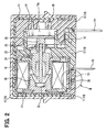
- the electromagnetic relay of the present embodiment has a resin case 10 having a rectangular parallelepiped shape, and the case 10 includes a first case 11, a second case 12, a third case 13, and a cover 15.
- the first case 11 has a tubular shape with a bottom end, and also, the second case 12 has a tubular shape with a bottom end.
- the third case 13 is provided between the first case 11 and the second case 12.
- the cover 15 is made of a resin and has a tubular shape with a bottom end.
- the first case 11 is provided with multiple ventilation holes 111. More specifically, the first case 11 has nine ventilation holes 111 in the present embodiment.
- the case 10 has a housing space 10a therein, and the housing space 10a is communicated with the external space outside the case 10 through the multiple ventilation holes 111.
- the case 10 is fitted into a rubber cover 14 that limits noise and vibration. Also, the rubber cover 14 is fitted into the resin cover 15. Both the rubber cover 14 and the resin cover 15 have rectangular parallelepiped shape. Each of the covers 14, 15 has an opening at one end and a bottom at the other end.
- the case 10 has five faces that are not provided with the ventilation holes 111, and the above five faces are covered by the rubber cover 14 and the resin cover 15.
- the third case 13 has two fixed contact supports 16 fixed thereto.
- the fixed contact supports 16 are made of a conductive metal.
- Each of the fixed contact supports 16 extends through the case 10 and has one end positioned within the housing space 10a and has the other end positioned at the external space outside the case 10.
- the one end of each of the fixed contact supports 16 within the housing space 10a is crimped to and fixed to a fixed contact 17 made of a conductive metal.
- the fixed contacts 17 are provided at predetermined positions by the fixed contact supports 16, respectively.
- each of the fixed contact supports 16 in the external space is provided with a load circuit terminal 161 that is connected with an external harness (not shown).
- the load circuit terminal 161 of one of the fixed contact supports 16 is connected with a lithium ion battery (not shown) through the external harness, and the load circuit terminal 161 of the other one of the fixed contact supports 16 is connected to the inverter circuit (not shown) through the external harness.
- the first case 11 has therein a hollow cylindrical coil 18 that generates an electromagnetic force when the coil 18 is energized.
- the coil 18 is connected with two coil terminals 19 that are made of a conductive metal. One end of each of the coil terminals 19 extends to an exterior of the case 10, and is connected to an ECU (not shown) through the external harness, and the coil 18 is energized through the external harnesses and the coil terminals 19.
- the coil 18 receives therein a fixed core 20 that is made of a magnetic metal, and there is a magnetic metal yoke 21 that is located at one longitudinal end of the coil 18 and at a position radially outward of the coil 18.
- the yoke 21 has both ends that are fitted with the second case 12 such that the yoke 21 is fixed to the second case 12.
- the fixed core 20 is supported by the yoke 21.
- a magnetic metal movable core 22 disposed at a certain position radially inward of the coil 18 and disposed within the third case 13 such that the movable core 22 is opposed to the fixed core 20.
- a return spring 23 is provided between the fixed core 20 and the movable core 22 such that the return spring 23 urges the movable core 22 in a direction away from the fixed core 20.
- the plate 24 is made of a magnetic metal and slidably holds the movable core 22. It should be noted that the fixed core 20, the yoke 21, the movable core 22, and the plate 24 forms a magnetic circuit of a magnetic flux induced by the coil 18.
- a metal shaft 25 extends through the movable core 22 and is fixed to the movable core 22.
- the shaft 25 has one end portion that extends to be placed within the third case 13.
- the one end portion of the shaft 25 is fitted with and fixed to an electrical insulator 26 that is made of a resin having an electrically non-conductive property.
- the electrical insulator 26 is positioned within the third case 13.
- a plate movable body 27 that is made of a conductive metal is provided within the third case 13. There is provided a pressure spring 28 between the movable body 27 and the second case 12, and the pressure spring 28 urges the movable body 27 toward the shaft 25.
- Two movable contacts 29 made of a conductive metal are crimped to and fixed to the movable body 27 at certain positions such that the movable contacts 29 are opposed to the respective fixed contacts 17.
- the movable contact 29 is movable to contact the fixed contact 17 and to be separate from the fixed contact 17.
- the first case 11 has a wall that corresponds to the face provided with the ventilation holes 111, and the above wall of the first case 11 has a flat recess 112 formed therein.
- the recess 112 has a generally rectangular parallelepiped shape and provides communication between the housing space 10a and the ventilation holes 111.
- the recess 112 has an opening portion that opens to the housing space 10a, and the opening portion has a flat rectangular shape when observed from the housing space 10a.
- the opening portion of the recess 112 has the flat rectangular shape when observed in a direction along the shaft 25 from the housing space 10a.
- the recess 112 receives therein a plate metal heat absorber 30 configured to cool flame that passes through the recess 112. More specifically, the heat absorber 30 is made of copper and has a generally flat rectangular parallelepiped shape. It should be noted that the heat absorber 30 serves as a cooling member.
- the recess 112 is defined by a first internal wall surface and a second internal wall surface of the first case 11 of the case 10.
- the first internal wall surface has the ventilation holes 111 opening thereon, and the second internal wall surface is opposed to the first internal wall surface in a direction generally perpendicular to the plane of the heat absorber 30, for example.
- a first flat passage 113 is formed between the heat absorber 30 and the first internal wall surface of the first case 11.
- the first flat passage 113 has a generally flat rectangular parallelepiped shape.
- a second flat passage 114 is formed between the heat absorber 30 and the second internal wall surface of the first case 11.
- the second flat passage 114 has a generally flat rectangular parallelepiped shape.
- the first flat passage 113 has a clearance dimension S that is measured between the heat absorber 30 and the internal wall surface of the first case 11, at which the ventilation holes 111 are formed.
- the clearance dimension S of the first flat passage 113 is designed to be a dimension such that it is possible to extinguish the flame that passes through the first flat passage 113. More specifically, the clearance dimension S is equal to or smaller than 0.15 mm.
- a passage length L1. is measured between the opening portion of the first flat passage 113 to one of the ventilation holes 111, which is closest to the opening portion of the first flat passage 113. In the above condition, the passage length L1 is equal to or greater than 1.5 mm.
- the ventilation holes 111 are circular holes or have circular cross sections. Also, all of the ventilation holes 111 are located at certain positions such that the ventilation holes 111 are opposed to the heat absorber 30.
- Each of the ventilation holes 111 has an inner diameter d (or passage area) having a certain dimension (or certain passage area) such that flame is extinguished.
- the inner diameter d (or passage area) is set to be a certain value such that it is possible to extinguish flame.
- the inner diameter d is designed to be equal to or less than 0.75 mm.
- each of the ventilation holes 111 has a hole length L2 that is equal to or greater than 2 mm (see FIG. 4 ).
- the return spring 23 urges the movable core 22 and the movable body 27 in a direction away from the fixed core against the urging force of the pressure spring 28.
- the two movable contacts 29 are moved apart from the two fixed contacts 17, and thereby the conduction between the load circuit terminals 161 is disabled.
- the electromagnetic relay of the present embodiment is employed in an environment, where combustible gas may be generated. Also, when combustible gas is generated, combustible gas flows into the housing space 10a through the ventilation holes 111 of the case 10, and combustible gas that has entered into the housing space 10a may be ignited by electric arc generated between the fixed contacts 17 and the movable contacts 29.
- Flame of the ignited combustible gas by electric arc may move toward the ventilation holes 111 from the housing space 10a through the first flat passage 113.
- heat of the flame is taken away by the first case 11 and the heat absorber 30, and thereby it is impossible to maintain the flame. As a result, flame disappears eventually.
- flame of combustible gas ignited by electric arc may flows into the second flat passage 114 from the housing space 10a, and subsequently flow toward the ventilation holes 111 through the first flat passage 113.
- heat of flame is taken away by the first case 11 and the heat absorber 30.
- heat of flame is also taken away by the first case 11 and the heat absorber 30 when flame passes through the first flat passage 113, and thereby it is impossible to maintain the flame.
- flame disappears.
- the heat absorber 30 is made of a metal that has a heat capacity greater than a heat capacity of a resin, it is possible to take away more heat from flame that passes through the first flat passage 113 and the second flat passage 114.
- the multiple ventilation holes 111 are provided, it is possible to sufficiently obtain a total passage area of the ventilation holes 111, and thereby sufficient ventilation is reliably achievable.
- each of the ventilation holes 111 has a cross section of a circular shape.
- the ventilation hole 111 may alternatively have another cross-sectional shape (for example, a rectangular shape) other than the circular shape.
- the ventilation holes 111 are provided to be opposed to the heat absorber 30.
- the ventilation holes 111 may be arranged at a position such that the ventilation holes 111 are not opposed to the heat absorber 30.
- the present embodiment employs a different method for fixing the heat absorber 30 different from a method in the first embodiment, and does not employ the recess 112 of the first embodiment.
- Other structure of the present embodiment is similar to the structure in the first embodiment.
- the first case 11 is formed with a through bore 115 adjacent the ventilation holes 111.
- the heat absorber 30 is bent to have an L-shape and has a press-fit plate portion 301 and a cover plate portion 302.
- the press-fit plate portion 301 is press fitted into the through bore 115, and the cover plate portion 302 is positioned within the first case 11 to cover the ventilation holes 111.
- the heat absorber 30 is fixed to the first case 11 by press fitting the press-fit plate portion 301 into the through bore 115, and thereby the recess 112 is not required in the present embodiment (see FIG. 3 ).
- the first flat passage 113 is formed between the cover plate portion 302 and an internal wall surface of the first case 11.
- the clearance dimension S of the first flat passage 113 is measured between the cover plate portion 302 and the internal wall surface of the first case 11.
- the clearance dimension S of the first flat passage 113 is designed such that it is possible to extinguish flame that passes through the first flat passage 113.
- Part of flame of combustible gas ignited by electric arc may spread toward the ventilation holes 111 from the housing space 10a through the first flat passage 113. Heat of the above flame is taken away by the first case 11 and the heat absorber 30 when flame passes through the first flat passage 113.
- the heat absorber 30 covers the ventilation holes 111.
- the coil terminals 19 that are made of the conductive metal may also serve as a heat absorber.
- the coil terminal 19 may be bent as required to form a counterpart that corresponds to the cover plate portion 302 of the heat absorber 30.
- the counterpart covers the ventilation holes 111.
- the coil terminal 19 may serve as a cooling member.
Description
- The present invention relates to an electromagnetic relay that opens and closes an electrical circuit.
- A conventional electromagnetic relay described in
JP-A-2005-203290 - However, when the conventional electromagnetic relay having the ventilation hole is used in a condition, where combustible gas is generated, combustible gas may enter into the housing space through the ventilation hole, and thereby combustible gas that has entered into the housing space may be ignited by electric arc generated between the movable contact and the fixed contact. If the generated flame may spread to the external space of the case through the ventilation hole, combustible gas in the external space of the case may be ignited disadvantageously.
- The document
FR 2 315 759 - The present invention is made in view of the above disadvantages, and thereby it is an objective of the present invention to limit flame of ignited combustible gas ignited by electric arc from spreading to an external space of a case.
- To achieve the objective of the present invention, there is provided an electromagnetic relay that includes a resin case, a coil, a movable contact, a fixed contact, a flat recess, a ventilation hole, a metal plate cooling member, and a flat passage. The resin case has a housing space therein. The coil is located within the housing space for generating an electromagnetic force when the coil is energized. The movable contact is located within the housing space, wherein the movable contact is actuated by the coil. The fixed contact is located within the housing space, and the movable contact is movable to contact the fixed contact and to be separate from the fixed contact. The flat recess is formed at the case, and the flat recess is communicated with the housing space. The ventilation hole is formed at the case, and the ventilation hole provides communication between the recess and an external space of the case. The metal plate cooling member is located within the recess, and the cooling member cools flame that passes through the recess. The flat passage is formed between the cooling member and an internal wall surface of the case, by which surface the recess is defined. The flat passage has a clearance dimension measured between the cooling member and the internal wall surface of the case. The clearance dimension of the flat passage is designed to be a dimension such that flame is extinguished.
- To achieve the objective of the present invention, there is also provided an electromagnetic relay that includes a resin case, a coil, a movable contact, a fixed contact, a ventilation hole, a metal plate cooling member, and a flat passage. The resin case has a housing space therein. The coil is located within the housing space for generating an electromagnetic force when the coil is energized. The movable contact is located within the housing space, wherein the movable contact is actuated by the coil. The fixed contact is located within the housing space, and the movable contact is movable to contact the fixed contact and to be separate from the fixed contact. The ventilation hole is formed at the case, and the ventilation hole provides communication between the housing space and an external space of the case. The metal plate cooling member is provided within the housing space to be opposed to the ventilation hole. The flat passage is defined between the metal plate cooling member and the case. The metal plate cooling member cools flame that passes through the flat passage. The flat passage has a clearance dimension measured between the cooling member and the case. The clearance dimension of the flat passage is designed such that flame is extinguished.
- The invention, together with additional objectives, features and advantages thereof, will be best understood from the following description, the appended claims and the accompanying drawings in which:
-
FIG. 1 is a cross-sectional view of a part of an electromagnetic relay according to the first embodiment of the present invention; -
FIG. 2 is a cross-sectional view taken along a line II-II ofFIG. 1 ; -
FIG. 3 is an enlarged cross-sectional view of a part III inFIG. 2 ; -
FIG. 4 is a cross-sectional view taken along a line IV-IV ofFIG. 3 ; and -
FIG. 5 is a cross-sectional view of a part of an electromagnetic relay according to the second embodiment of the present invention. - Embodiments of the present invention will be described with reference to accompanying drawings. It should be noted that similar components of one embodiment of the present specification, which are similar to the components of the other embodiment, will be designated by the same numerals.
- An electromagnetic relay of the present embodiment is applied to a hybrid vehicle or an electric vehicle, each of which has an electric motor as a travel drive source. More specifically, the hybrid vehicle is mounted with a lithium ion battery that supplies electric power to an electric motor. Also, there is provided an electromagnetic relay in an electrical circuit that has the lithium ion battery (high-voltage DC power source) and an inverter circuit for driving a vehicle.
- Battery fluid of a lithium ion battery includes organic solvent, such as dimethyl carbonate (DMC) or ethyl methyl carbonate (EMC). Thus, when temperature of the battery fluid increases, for example, due to overcharge, hydrogen gas is generated, and dimethyl carbonate or ethyl methyl carbonate is evaporated. The above hydrogen gas, dimethyl carbonate gas, and ethyl methyl carbonate gas are combustible gas.
- It should be noted that the electromagnetic relay of the present embodiment is applicable to an electric vehicle mounted with a fuel cell. The fuel cell employs hydrogen gas that serves as combustible gas.
- As shown in
FIGS. 1 and2 , the electromagnetic relay of the present embodiment has aresin case 10 having a rectangular parallelepiped shape, and thecase 10 includes afirst case 11, asecond case 12, athird case 13, and acover 15. Thefirst case 11 has a tubular shape with a bottom end, and also, thesecond case 12 has a tubular shape with a bottom end. Thethird case 13 is provided between thefirst case 11 and thesecond case 12. Thecover 15 is made of a resin and has a tubular shape with a bottom end. Thefirst case 11 is provided withmultiple ventilation holes 111. More specifically, thefirst case 11 has nineventilation holes 111 in the present embodiment. Thecase 10 has ahousing space 10a therein, and thehousing space 10a is communicated with the external space outside thecase 10 through themultiple ventilation holes 111. - The
case 10 is fitted into arubber cover 14 that limits noise and vibration. Also, therubber cover 14 is fitted into theresin cover 15. Both therubber cover 14 and theresin cover 15 have rectangular parallelepiped shape. Each of thecovers case 10 has five faces that are not provided with theventilation holes 111, and the above five faces are covered by therubber cover 14 and theresin cover 15. - The
third case 13 has two fixed contact supports 16 fixed thereto. The fixedcontact supports 16 are made of a conductive metal. Each of the fixed contact supports 16 extends through thecase 10 and has one end positioned within thehousing space 10a and has the other end positioned at the external space outside thecase 10. The one end of each of the fixed contact supports 16 within thehousing space 10a is crimped to and fixed to a fixedcontact 17 made of a conductive metal. Thefixed contacts 17 are provided at predetermined positions by the fixed contact supports 16, respectively. - The other end of each of the fixed contact supports 16 in the external space is provided with a
load circuit terminal 161 that is connected with an external harness (not shown). Theload circuit terminal 161 of one of the fixed contact supports 16 is connected with a lithium ion battery (not shown) through the external harness, and theload circuit terminal 161 of the other one of the fixed contact supports 16 is connected to the inverter circuit (not shown) through the external harness. - The
first case 11 has therein a hollowcylindrical coil 18 that generates an electromagnetic force when thecoil 18 is energized. Thecoil 18 is connected with twocoil terminals 19 that are made of a conductive metal. One end of each of thecoil terminals 19 extends to an exterior of thecase 10, and is connected to an ECU (not shown) through the external harness, and thecoil 18 is energized through the external harnesses and thecoil terminals 19. - The
coil 18 receives therein a fixedcore 20 that is made of a magnetic metal, and there is amagnetic metal yoke 21 that is located at one longitudinal end of thecoil 18 and at a position radially outward of thecoil 18. Theyoke 21 has both ends that are fitted with thesecond case 12 such that theyoke 21 is fixed to thesecond case 12. The fixedcore 20 is supported by theyoke 21. - There is a magnetic metal
movable core 22 disposed at a certain position radially inward of thecoil 18 and disposed within thethird case 13 such that themovable core 22 is opposed to the fixedcore 20. Also, areturn spring 23 is provided between the fixedcore 20 and themovable core 22 such that thereturn spring 23 urges themovable core 22 in a direction away from the fixedcore 20. When thecoil 18 is energized, themovable core 22 is attracted toward the fixedcore 20 against the urging force of thereturn spring 23. - There is a flanged hollow
cylindrical plate 24 provided at the other longitudinal end of thecoil 18. Theplate 24 is made of a magnetic metal and slidably holds themovable core 22. It should be noted that the fixedcore 20, theyoke 21, themovable core 22, and theplate 24 forms a magnetic circuit of a magnetic flux induced by thecoil 18. - A
metal shaft 25 extends through themovable core 22 and is fixed to themovable core 22. Theshaft 25 has one end portion that extends to be placed within thethird case 13. The one end portion of theshaft 25 is fitted with and fixed to anelectrical insulator 26 that is made of a resin having an electrically non-conductive property. Theelectrical insulator 26 is positioned within thethird case 13. - A plate
movable body 27 that is made of a conductive metal is provided within thethird case 13. There is provided apressure spring 28 between themovable body 27 and thesecond case 12, and thepressure spring 28 urges themovable body 27 toward theshaft 25. Twomovable contacts 29 made of a conductive metal are crimped to and fixed to themovable body 27 at certain positions such that themovable contacts 29 are opposed to the respective fixedcontacts 17. Themovable contact 29 is movable to contact the fixedcontact 17 and to be separate from the fixedcontact 17. - As shown in
FIGS. 3 and4 , thefirst case 11 has a wall that corresponds to the face provided with the ventilation holes 111, and the above wall of thefirst case 11 has aflat recess 112 formed therein. Therecess 112 has a generally rectangular parallelepiped shape and provides communication between thehousing space 10a and the ventilation holes 111. Therecess 112 has an opening portion that opens to thehousing space 10a, and the opening portion has a flat rectangular shape when observed from thehousing space 10a. For example, the opening portion of therecess 112 has the flat rectangular shape when observed in a direction along theshaft 25 from thehousing space 10a. - The
recess 112 receives therein a platemetal heat absorber 30 configured to cool flame that passes through therecess 112. More specifically, theheat absorber 30 is made of copper and has a generally flat rectangular parallelepiped shape. It should be noted that theheat absorber 30 serves as a cooling member. - The
recess 112 is defined by a first internal wall surface and a second internal wall surface of thefirst case 11 of thecase 10. The first internal wall surface has the ventilation holes 111 opening thereon, and the second internal wall surface is opposed to the first internal wall surface in a direction generally perpendicular to the plane of theheat absorber 30, for example. A firstflat passage 113 is formed between theheat absorber 30 and the first internal wall surface of thefirst case 11. The firstflat passage 113 has a generally flat rectangular parallelepiped shape. Also, a secondflat passage 114 is formed between theheat absorber 30 and the second internal wall surface of thefirst case 11. The secondflat passage 114 has a generally flat rectangular parallelepiped shape. - The first
flat passage 113 has a clearance dimension S that is measured between theheat absorber 30 and the internal wall surface of thefirst case 11, at which the ventilation holes 111 are formed. The clearance dimension S of the firstflat passage 113 is designed to be a dimension such that it is possible to extinguish the flame that passes through the firstflat passage 113. More specifically, the clearance dimension S is equal to or smaller than 0.15 mm. Also, a passage length L1. is measured between the opening portion of the firstflat passage 113 to one of the ventilation holes 111, which is closest to the opening portion of the firstflat passage 113. In the above condition, the passage length L1 is equal to or greater than 1.5 mm. - It should be noted that the ventilation holes 111 are circular holes or have circular cross sections. Also, all of the ventilation holes 111 are located at certain positions such that the ventilation holes 111 are opposed to the
heat absorber 30. Each of the ventilation holes 111 has an inner diameter d (or passage area) having a certain dimension (or certain passage area) such that flame is extinguished. In other words, the inner diameter d (or passage area) is set to be a certain value such that it is possible to extinguish flame. Specifically, the inner diameter d is designed to be equal to or less than 0.75 mm. Also, each of the ventilation holes 111 has a hole length L2 that is equal to or greater than 2 mm (seeFIG. 4 ). - Next, operation of the electromagnetic relay of the present embodiment will be described. Firstly, when the
coil 18 is energized, the electromagnetic force attracts themovable core 22 toward the fixedcore 20 against the force of thereturn spring 23, and thereby themovable body 27 is urged by thepressure spring 28 such that themovable body 27 is displaced to follow themovable core 22. As a result, the twomovable contacts 29 contact the two fixedcontacts 17, respectively, and thus establishing the conduction between the twoload circuit terminals 161. - In contrast, when the
coil 18 is deenergized, thereturn spring 23 urges themovable core 22 and themovable body 27 in a direction away from the fixed core against the urging force of thepressure spring 28. As a result, the twomovable contacts 29 are moved apart from the two fixedcontacts 17, and thereby the conduction between theload circuit terminals 161 is disabled. - As above, the electromagnetic relay of the present embodiment is employed in an environment, where combustible gas may be generated. Also, when combustible gas is generated, combustible gas flows into the
housing space 10a through the ventilation holes 111 of thecase 10, and combustible gas that has entered into thehousing space 10a may be ignited by electric arc generated between the fixedcontacts 17 and themovable contacts 29. - Flame of the ignited combustible gas by electric arc may move toward the ventilation holes 111 from the
housing space 10a through the firstflat passage 113. When the flame passes through the firstflat passage 113, heat of the flame is taken away by thefirst case 11 and theheat absorber 30, and thereby it is impossible to maintain the flame. As a result, flame disappears eventually. - Also, flame of combustible gas ignited by electric arc may flows into the second
flat passage 114 from thehousing space 10a, and subsequently flow toward the ventilation holes 111 through the firstflat passage 113. When flame passes through the secondflat passage 114, heat of flame is taken away by thefirst case 11 and theheat absorber 30. Furthermore, heat of flame is also taken away by thefirst case 11 and theheat absorber 30 when flame passes through the firstflat passage 113, and thereby it is impossible to maintain the flame. As a result, flame disappears. In the present embodiment, because theheat absorber 30 is made of a metal that has a heat capacity greater than a heat capacity of a resin, it is possible to take away more heat from flame that passes through the firstflat passage 113 and the secondflat passage 114. - As a result, it is possible to limit flame of combustible gas ignited by electric arc from spreading to the external space of the
case 10, and thereby it is possible to prevent the ignition of combustible gas in the external space of thecase 10. - Furthermore, even in a case, where flame does not disappear while flame passes through the first
flat passage 113, heat of flame is further taken away by thefirst case 11 when flame subsequently passes through the ventilation holes 111. As a result, it is possible to extinguish flame. As a result, it is possible to reliably prevent flame of combustible gas that is ignited by electric arc from spreading to the external space outside thecase 10. - Also, in the present embodiment, because the
multiple ventilation holes 111 are provided, it is possible to sufficiently obtain a total passage area of the ventilation holes 111, and thereby sufficient ventilation is reliably achievable. - In the present embodiment, each of the ventilation holes 111 has a cross section of a circular shape. However, the
ventilation hole 111 may alternatively have another cross-sectional shape (for example, a rectangular shape) other than the circular shape. Also, in the present embodiment, the ventilation holes 111 are provided to be opposed to theheat absorber 30. However, the ventilation holes 111 may be arranged at a position such that the ventilation holes 111 are not opposed to theheat absorber 30. - The present embodiment employs a different method for fixing the
heat absorber 30 different from a method in the first embodiment, and does not employ therecess 112 of the first embodiment. Other structure of the present embodiment is similar to the structure in the first embodiment. - As shown in
FIG. 5 , thefirst case 11 is formed with a throughbore 115 adjacent the ventilation holes 111. Theheat absorber 30 is bent to have an L-shape and has a press-fit plate portion 301 and acover plate portion 302. The press-fit plate portion 301 is press fitted into the throughbore 115, and thecover plate portion 302 is positioned within thefirst case 11 to cover the ventilation holes 111. - The
heat absorber 30 is fixed to thefirst case 11 by press fitting the press-fit plate portion 301 into the throughbore 115, and thereby therecess 112 is not required in the present embodiment (seeFIG. 3 ). - The first
flat passage 113 is formed between thecover plate portion 302 and an internal wall surface of thefirst case 11. The clearance dimension S of the firstflat passage 113 is measured between thecover plate portion 302 and the internal wall surface of thefirst case 11. The clearance dimension S of the firstflat passage 113 is designed such that it is possible to extinguish flame that passes through the firstflat passage 113. - Part of flame of combustible gas ignited by electric arc may spread toward the ventilation holes 111 from the
housing space 10a through the firstflat passage 113. Heat of the above flame is taken away by thefirst case 11 and theheat absorber 30 when flame passes through the firstflat passage 113. - As a result, it is impossible to maintain the flame, and thereby flame disappears or is extinguished.
- In the present embodiment, the
heat absorber 30 covers the ventilation holes 111. However, thecoil terminals 19 that are made of the conductive metal may also serve as a heat absorber. Specifically, thecoil terminal 19 may be bent as required to form a counterpart that corresponds to thecover plate portion 302 of theheat absorber 30. In the above case, the counterpart covers the ventilation holes 111. As above, thecoil terminal 19 may serve as a cooling member.
Claims (5)
- An electromagnetic relay comprising:a resin case (10) having a housing space (10a) therein;a coil (18) located within the housing space (10a) for generating an electromagnetic force when the coil (18) is energized;a movable contact (29) located within the housing space (10a), wherein the movable contact (29) is actuated by the coil (18);a fixed contact (17) located within the housing space (10a), wherein the movable contact (29) is movable to contact the fixed contact (17) and to be separate from the fixed contact (17); a ventilation hole (111) that is formed at the case (10), characterized bya flat recess (112) that is formed at the case (10), wherein the flat recess (112) is communicated with the housing space (10a);the ventilation hole (111) provides communication between the recess (112) and an external space of the case (10);a metal plate cooling member (30) located within the recess (112), wherein the cooling member (30) cools flame that passes through the recess (112); anda flat passage (113, 114) that is formed between the cooling member (30) and an internal wall surface of the case (10), by which surface the recess (112) is defined, wherein:the flat passage (113, 114) has a clearance dimension (S) measured between the cooling member (30) and the internal wall surface of the case (10); andthe clearance dimension (S) of the flat passage (113, 114) is designed to be a dimension such that flame is extinguished.
- The electromagnetic relay according to claim 1, wherein the ventilation hole (111) has a passage area such that flame is extinguished.
- The electromagnetic relay according to claim 1 or 2, wherein the ventilation hole (111) is one of a plurality of ventilation holes (111).
- The electromagnetic relay according to any one of claims 1 through 3, wherein the ventilation hole (111) has a circular cross section.
- The electromagnetic relay according to claim 1, wherein the ventilation hole (111) is positioned to be opposed to the cooling member (30).
Priority Applications (1)
| Application Number | Priority Date | Filing Date | Title |
|---|---|---|---|
| EP10014838A EP2287868B1 (en) | 2009-02-02 | 2010-01-21 | Electromagnetic relay |
Applications Claiming Priority (1)
| Application Number | Priority Date | Filing Date | Title |
|---|---|---|---|
| JP2009021438A JP5131219B2 (en) | 2009-02-02 | 2009-02-02 | Electromagnetic relay |
Related Child Applications (2)
| Application Number | Title | Priority Date | Filing Date |
|---|---|---|---|
| EP10014838A Division-Into EP2287868B1 (en) | 2009-02-02 | 2010-01-21 | Electromagnetic relay |
| EP10014838.6 Division-Into | 2010-11-22 |
Publications (3)
| Publication Number | Publication Date |
|---|---|
| EP2214192A2 EP2214192A2 (en) | 2010-08-04 |
| EP2214192A3 EP2214192A3 (en) | 2011-04-13 |
| EP2214192B1 true EP2214192B1 (en) | 2014-01-15 |
Family
ID=41800620
Family Applications (2)
| Application Number | Title | Priority Date | Filing Date |
|---|---|---|---|
| EP10014838A Active EP2287868B1 (en) | 2009-02-02 | 2010-01-21 | Electromagnetic relay |
| EP10000607.1A Active EP2214192B1 (en) | 2009-02-02 | 2010-01-21 | Electromagnetic relay |
Family Applications Before (1)
| Application Number | Title | Priority Date | Filing Date |
|---|---|---|---|
| EP10014838A Active EP2287868B1 (en) | 2009-02-02 | 2010-01-21 | Electromagnetic relay |
Country Status (4)
| Country | Link |
|---|---|
| US (1) | US8164404B2 (en) |
| EP (2) | EP2287868B1 (en) |
| JP (1) | JP5131219B2 (en) |
| CN (1) | CN101794680B (en) |
Families Citing this family (23)
| Publication number | Priority date | Publication date | Assignee | Title |
|---|---|---|---|---|
| JP5131218B2 (en) * | 2008-09-12 | 2013-01-30 | アンデン株式会社 | Electromagnetic relay |
| EP2728604A4 (en) * | 2011-06-28 | 2015-03-18 | Mitsuba Corp | Electromagnetic relay |
| JP6048812B2 (en) * | 2012-12-18 | 2016-12-21 | Nok株式会社 | Rubber cap for relay |
| JP6265657B2 (en) * | 2013-08-26 | 2018-01-24 | 富士通コンポーネント株式会社 | Electromagnetic relay |
| JP6202943B2 (en) * | 2013-08-26 | 2017-09-27 | 富士通コンポーネント株式会社 | Electromagnetic relay |
| DE102014006957A1 (en) * | 2014-05-12 | 2015-11-12 | Tyco Electronics Austria Gmbh | Switching element for use in a potentially explosive area |
| JP6258138B2 (en) * | 2014-07-03 | 2018-01-10 | 富士通コンポーネント株式会社 | Electromagnetic relay |
| JP6422249B2 (en) * | 2014-07-03 | 2018-11-14 | 富士通コンポーネント株式会社 | Electromagnetic relay |
| KR101887316B1 (en) * | 2014-07-23 | 2018-08-09 | 후지쯔 콤포넌트 가부시끼가이샤 | Electromagnetic relay |
| JP6433706B2 (en) | 2014-07-28 | 2018-12-05 | 富士通コンポーネント株式会社 | Electromagnetic relay and coil terminal |
| US10229803B2 (en) | 2015-08-09 | 2019-03-12 | Microsemi Corporation | High voltage relay systems and methods |
| JP6667257B2 (en) * | 2015-10-28 | 2020-03-18 | アンデン株式会社 | Electromagnetic relay |
| JP6551339B2 (en) * | 2015-11-17 | 2019-07-31 | アンデン株式会社 | Electromagnetic relay |
| JP6536472B2 (en) * | 2016-04-28 | 2019-07-03 | 株式会社デンソー | solenoid |
| CN108022796A (en) * | 2016-11-01 | 2018-05-11 | 贵州天义电器有限责任公司 | D.C. contactor |
| CN109859991B (en) * | 2017-11-30 | 2020-08-07 | 比亚迪股份有限公司 | Relay with a movable contact |
| CN109243878B (en) * | 2018-09-14 | 2023-10-20 | 浙江现代电气有限公司 | Three-position opening and closing operating mechanism of change-over switch |
| JP7145465B2 (en) * | 2018-11-12 | 2022-10-03 | パナソニックIpマネジメント株式会社 | Contact devices and electromagnetic relays |
| JP7326739B2 (en) * | 2018-12-27 | 2023-08-16 | オムロン株式会社 | electronic components |
| JP6945171B2 (en) * | 2019-06-26 | 2021-10-06 | パナソニックIpマネジメント株式会社 | Electromagnetic relay |
| JP7423944B2 (en) * | 2019-09-13 | 2024-01-30 | オムロン株式会社 | electromagnetic relay |
| US20210247096A1 (en) * | 2020-02-07 | 2021-08-12 | Carrier Corporation | A2l compliant contactor |
| JP7067580B2 (en) * | 2020-03-18 | 2022-05-16 | 株式会社デンソーエレクトロニクス | Electromagnetic relay and manufacturing method of electromagnetic relay |
Family Cites Families (11)
| Publication number | Priority date | Publication date | Assignee | Title |
|---|---|---|---|---|
| DE2616005A1 (en) | 1975-06-25 | 1976-12-30 | Esterline Electronics | HOUSING FOR AN ELECTROMAGNETIC RELAY |
| JPS60147052U (en) * | 1984-03-08 | 1985-09-30 | オムロン株式会社 | sealed relay |
| JPS63187239U (en) * | 1987-05-26 | 1988-11-30 | ||
| US5015979A (en) * | 1988-12-15 | 1991-05-14 | Omron Tateisi Electronics Co. | Electromagnetic relay |
| EP0484587B1 (en) * | 1990-11-09 | 1995-07-26 | Siemens Aktiengesellschaft | Electromagnetic relay with control unit |
| US6242707B1 (en) * | 1999-08-31 | 2001-06-05 | General Electric Company | Arc quenching current limiting device including ablative material |
| US6222147B1 (en) * | 2000-03-09 | 2001-04-24 | General Electric Company | Circuit breaker arc exhaust baffle with variable aperture |
| JP2005203290A (en) | 2004-01-19 | 2005-07-28 | Daiichi Denki Kk | Small-sized relay |
| US7586057B2 (en) * | 2006-11-16 | 2009-09-08 | Eaton Corporation | Electrical switching apparatus and vented case therefor |
| JP5131218B2 (en) * | 2008-09-12 | 2013-01-30 | アンデン株式会社 | Electromagnetic relay |
| US7843682B2 (en) * | 2008-10-22 | 2010-11-30 | Levitron Manufacturing Co., Inc. | Blast venting for electrical device |
-
2009
- 2009-02-02 JP JP2009021438A patent/JP5131219B2/en active Active
-
2010
- 2010-01-19 US US12/656,122 patent/US8164404B2/en active Active
- 2010-01-21 EP EP10014838A patent/EP2287868B1/en active Active
- 2010-01-21 EP EP10000607.1A patent/EP2214192B1/en active Active
- 2010-02-01 CN CN201010108948.0A patent/CN101794680B/en active Active
Also Published As
| Publication number | Publication date |
|---|---|
| EP2214192A3 (en) | 2011-04-13 |
| US8164404B2 (en) | 2012-04-24 |
| CN101794680B (en) | 2014-05-14 |
| JP5131219B2 (en) | 2013-01-30 |
| EP2287868B1 (en) | 2012-11-21 |
| EP2287868A2 (en) | 2011-02-23 |
| JP2010177165A (en) | 2010-08-12 |
| US20100193475A1 (en) | 2010-08-05 |
| CN101794680A (en) | 2010-08-04 |
| EP2287868A3 (en) | 2011-03-16 |
| EP2214192A2 (en) | 2010-08-04 |
Similar Documents
| Publication | Publication Date | Title |
|---|---|---|
| EP2214192B1 (en) | Electromagnetic relay | |
| JP5131218B2 (en) | Electromagnetic relay | |
| US10475610B2 (en) | Electric circuit breaker device | |
| US8451079B2 (en) | Electromagnetic solenoid | |
| US11929221B2 (en) | Interrupter and interrupter system | |
| CN108140512B (en) | Electromagnetic relay | |
| EP2151845A2 (en) | Electromagnetic switch equipped with built-in electronic control circuit | |
| CN109416999B (en) | Circuit breaker | |
| CN113270292A (en) | Circuit breaker | |
| JP4158180B2 (en) | Ignition device for internal combustion engine | |
| JP6986300B2 (en) | DC circuit breaker | |
| CN218069726U (en) | Relay device | |
| CN217983217U (en) | Contactor assembly and contactor | |
| WO2023152907A1 (en) | Electrical circuit switching device | |
| JP2013016349A (en) | Electromagnetic relay | |
| CN116313651A (en) | Double-body contactor | |
| CN115803834A (en) | Power switch arranged in a switch fuse box and switch fuse box of a motor vehicle | |
| CN115280456A (en) | Hermetic terminal and contact device using the same | |
| JP2021153045A (en) | Airtight terminal and contact device using the airtight terminal | |
| JP2021083160A (en) | Electric connection device | |
| KR20190048112A (en) | Relay Apparatus |
Legal Events
| Date | Code | Title | Description |
|---|---|---|---|
| PUAI | Public reference made under article 153(3) epc to a published international application that has entered the european phase |
Free format text: ORIGINAL CODE: 0009012 |
|
| AK | Designated contracting states |
Kind code of ref document: A2 Designated state(s): AT BE BG CH CY CZ DE DK EE ES FI FR GB GR HR HU IE IS IT LI LT LU LV MC MK MT NL NO PL PT RO SE SI SK SM TR |
|
| AX | Request for extension of the european patent |
Extension state: AL BA RS |
|
| RIN1 | Information on inventor provided before grant (corrected) |
Inventor name: KAMIYA, MAKOTO Inventor name: OZAKI, MANABU |
|
| PUAL | Search report despatched |
Free format text: ORIGINAL CODE: 0009013 |
|
| AK | Designated contracting states |
Kind code of ref document: A3 Designated state(s): AT BE BG CH CY CZ DE DK EE ES FI FR GB GR HR HU IE IS IT LI LT LU LV MC MK MT NL NO PL PT RO SE SI SK SM TR |
|
| AX | Request for extension of the european patent |
Extension state: AL BA RS |
|
| RIC1 | Information provided on ipc code assigned before grant |
Ipc: H01H 9/04 20060101ALI20110307BHEP Ipc: H01H 50/02 20060101AFI20100316BHEP |
|
| 17P | Request for examination filed |
Effective date: 20110329 |
|
| GRAP | Despatch of communication of intention to grant a patent |
Free format text: ORIGINAL CODE: EPIDOSNIGR1 |
|
| RIC1 | Information provided on ipc code assigned before grant |
Ipc: H01H 9/04 20060101ALI20130715BHEP Ipc: H01H 50/02 20060101AFI20130715BHEP |
|
| INTG | Intention to grant announced |
Effective date: 20130729 |
|
| RAP1 | Party data changed (applicant data changed or rights of an application transferred) |
Owner name: ANDEN CO., LTD. |
|
| GRAS | Grant fee paid |
Free format text: ORIGINAL CODE: EPIDOSNIGR3 |
|
| GRAA | (expected) grant |
Free format text: ORIGINAL CODE: 0009210 |
|
| AK | Designated contracting states |
Kind code of ref document: B1 Designated state(s): AT BE BG CH CY CZ DE DK EE ES FI FR GB GR HR HU IE IS IT LI LT LU LV MC MK MT NL NO PL PT RO SE SI SK SM TR |
|
| REG | Reference to a national code |
Ref country code: GB Ref legal event code: FG4D Ref country code: CH Ref legal event code: EP |
|
| REG | Reference to a national code |
Ref country code: AT Ref legal event code: REF Ref document number: 650145 Country of ref document: AT Kind code of ref document: T Effective date: 20140215 |
|
| REG | Reference to a national code |
Ref country code: DE Ref legal event code: R096 Ref document number: 602010013081 Country of ref document: DE Effective date: 20140220 |
|
| REG | Reference to a national code |
Ref country code: IE Ref legal event code: FG4D |
|
| REG | Reference to a national code |
Ref country code: NL Ref legal event code: VDEP Effective date: 20140115 |
|
| REG | Reference to a national code |
Ref country code: AT Ref legal event code: MK05 Ref document number: 650145 Country of ref document: AT Kind code of ref document: T Effective date: 20140115 |
|
| REG | Reference to a national code |
Ref country code: LT Ref legal event code: MG4D |
|
| PG25 | Lapsed in a contracting state [announced via postgrant information from national office to epo] |
Ref country code: NO Free format text: LAPSE BECAUSE OF FAILURE TO SUBMIT A TRANSLATION OF THE DESCRIPTION OR TO PAY THE FEE WITHIN THE PRESCRIBED TIME-LIMIT Effective date: 20140415 Ref country code: IS Free format text: LAPSE BECAUSE OF FAILURE TO SUBMIT A TRANSLATION OF THE DESCRIPTION OR TO PAY THE FEE WITHIN THE PRESCRIBED TIME-LIMIT Effective date: 20140515 Ref country code: LT Free format text: LAPSE BECAUSE OF FAILURE TO SUBMIT A TRANSLATION OF THE DESCRIPTION OR TO PAY THE FEE WITHIN THE PRESCRIBED TIME-LIMIT Effective date: 20140115 |
|
| PG25 | Lapsed in a contracting state [announced via postgrant information from national office to epo] |
Ref country code: PT Free format text: LAPSE BECAUSE OF FAILURE TO SUBMIT A TRANSLATION OF THE DESCRIPTION OR TO PAY THE FEE WITHIN THE PRESCRIBED TIME-LIMIT Effective date: 20140515 Ref country code: AT Free format text: LAPSE BECAUSE OF FAILURE TO SUBMIT A TRANSLATION OF THE DESCRIPTION OR TO PAY THE FEE WITHIN THE PRESCRIBED TIME-LIMIT Effective date: 20140115 Ref country code: ES Free format text: LAPSE BECAUSE OF FAILURE TO SUBMIT A TRANSLATION OF THE DESCRIPTION OR TO PAY THE FEE WITHIN THE PRESCRIBED TIME-LIMIT Effective date: 20140115 Ref country code: CY Free format text: LAPSE BECAUSE OF FAILURE TO SUBMIT A TRANSLATION OF THE DESCRIPTION OR TO PAY THE FEE WITHIN THE PRESCRIBED TIME-LIMIT Effective date: 20140115 Ref country code: SE Free format text: LAPSE BECAUSE OF FAILURE TO SUBMIT A TRANSLATION OF THE DESCRIPTION OR TO PAY THE FEE WITHIN THE PRESCRIBED TIME-LIMIT Effective date: 20140115 Ref country code: NL Free format text: LAPSE BECAUSE OF FAILURE TO SUBMIT A TRANSLATION OF THE DESCRIPTION OR TO PAY THE FEE WITHIN THE PRESCRIBED TIME-LIMIT Effective date: 20140115 Ref country code: FI Free format text: LAPSE BECAUSE OF FAILURE TO SUBMIT A TRANSLATION OF THE DESCRIPTION OR TO PAY THE FEE WITHIN THE PRESCRIBED TIME-LIMIT Effective date: 20140115 |
|
| REG | Reference to a national code |
Ref country code: CH Ref legal event code: PL |
|
| PG25 | Lapsed in a contracting state [announced via postgrant information from national office to epo] |
Ref country code: BE Free format text: LAPSE BECAUSE OF FAILURE TO SUBMIT A TRANSLATION OF THE DESCRIPTION OR TO PAY THE FEE WITHIN THE PRESCRIBED TIME-LIMIT Effective date: 20140115 Ref country code: LV Free format text: LAPSE BECAUSE OF FAILURE TO SUBMIT A TRANSLATION OF THE DESCRIPTION OR TO PAY THE FEE WITHIN THE PRESCRIBED TIME-LIMIT Effective date: 20140115 Ref country code: HR Free format text: LAPSE BECAUSE OF FAILURE TO SUBMIT A TRANSLATION OF THE DESCRIPTION OR TO PAY THE FEE WITHIN THE PRESCRIBED TIME-LIMIT Effective date: 20140115 |
|
| REG | Reference to a national code |
Ref country code: DE Ref legal event code: R097 Ref document number: 602010013081 Country of ref document: DE |
|
| PG25 | Lapsed in a contracting state [announced via postgrant information from national office to epo] |
Ref country code: RO Free format text: LAPSE BECAUSE OF FAILURE TO SUBMIT A TRANSLATION OF THE DESCRIPTION OR TO PAY THE FEE WITHIN THE PRESCRIBED TIME-LIMIT Effective date: 20140115 Ref country code: MC Free format text: LAPSE BECAUSE OF FAILURE TO SUBMIT A TRANSLATION OF THE DESCRIPTION OR TO PAY THE FEE WITHIN THE PRESCRIBED TIME-LIMIT Effective date: 20140115 Ref country code: CZ Free format text: LAPSE BECAUSE OF FAILURE TO SUBMIT A TRANSLATION OF THE DESCRIPTION OR TO PAY THE FEE WITHIN THE PRESCRIBED TIME-LIMIT Effective date: 20140115 Ref country code: LI Free format text: LAPSE BECAUSE OF NON-PAYMENT OF DUE FEES Effective date: 20140131 Ref country code: DK Free format text: LAPSE BECAUSE OF FAILURE TO SUBMIT A TRANSLATION OF THE DESCRIPTION OR TO PAY THE FEE WITHIN THE PRESCRIBED TIME-LIMIT Effective date: 20140115 Ref country code: CH Free format text: LAPSE BECAUSE OF NON-PAYMENT OF DUE FEES Effective date: 20140131 Ref country code: EE Free format text: LAPSE BECAUSE OF FAILURE TO SUBMIT A TRANSLATION OF THE DESCRIPTION OR TO PAY THE FEE WITHIN THE PRESCRIBED TIME-LIMIT Effective date: 20140115 |
|
| REG | Reference to a national code |
Ref country code: IE Ref legal event code: MM4A |
|
| PLBE | No opposition filed within time limit |
Free format text: ORIGINAL CODE: 0009261 |
|
| STAA | Information on the status of an ep patent application or granted ep patent |
Free format text: STATUS: NO OPPOSITION FILED WITHIN TIME LIMIT |
|
| PG25 | Lapsed in a contracting state [announced via postgrant information from national office to epo] |
Ref country code: SK Free format text: LAPSE BECAUSE OF FAILURE TO SUBMIT A TRANSLATION OF THE DESCRIPTION OR TO PAY THE FEE WITHIN THE PRESCRIBED TIME-LIMIT Effective date: 20140115 Ref country code: PL Free format text: LAPSE BECAUSE OF FAILURE TO SUBMIT A TRANSLATION OF THE DESCRIPTION OR TO PAY THE FEE WITHIN THE PRESCRIBED TIME-LIMIT Effective date: 20140115 |
|
| 26N | No opposition filed |
Effective date: 20141016 |
|
| GBPC | Gb: european patent ceased through non-payment of renewal fee |
Effective date: 20140415 |
|
| PG25 | Lapsed in a contracting state [announced via postgrant information from national office to epo] |
Ref country code: GB Free format text: LAPSE BECAUSE OF NON-PAYMENT OF DUE FEES Effective date: 20140415 Ref country code: IE Free format text: LAPSE BECAUSE OF NON-PAYMENT OF DUE FEES Effective date: 20140121 |
|
| REG | Reference to a national code |
Ref country code: DE Ref legal event code: R097 Ref document number: 602010013081 Country of ref document: DE Effective date: 20141016 |
|
| PG25 | Lapsed in a contracting state [announced via postgrant information from national office to epo] |
Ref country code: SI Free format text: LAPSE BECAUSE OF FAILURE TO SUBMIT A TRANSLATION OF THE DESCRIPTION OR TO PAY THE FEE WITHIN THE PRESCRIBED TIME-LIMIT Effective date: 20140115 |
|
| REG | Reference to a national code |
Ref country code: FR Ref legal event code: PLFP Year of fee payment: 7 |
|
| PG25 | Lapsed in a contracting state [announced via postgrant information from national office to epo] |
Ref country code: MT Free format text: LAPSE BECAUSE OF FAILURE TO SUBMIT A TRANSLATION OF THE DESCRIPTION OR TO PAY THE FEE WITHIN THE PRESCRIBED TIME-LIMIT Effective date: 20140115 |
|
| PG25 | Lapsed in a contracting state [announced via postgrant information from national office to epo] |
Ref country code: SM Free format text: LAPSE BECAUSE OF FAILURE TO SUBMIT A TRANSLATION OF THE DESCRIPTION OR TO PAY THE FEE WITHIN THE PRESCRIBED TIME-LIMIT Effective date: 20140115 |
|
| PG25 | Lapsed in a contracting state [announced via postgrant information from national office to epo] |
Ref country code: IT Free format text: LAPSE BECAUSE OF FAILURE TO SUBMIT A TRANSLATION OF THE DESCRIPTION OR TO PAY THE FEE WITHIN THE PRESCRIBED TIME-LIMIT Effective date: 20140115 Ref country code: GR Free format text: LAPSE BECAUSE OF FAILURE TO SUBMIT A TRANSLATION OF THE DESCRIPTION OR TO PAY THE FEE WITHIN THE PRESCRIBED TIME-LIMIT Effective date: 20140416 Ref country code: BG Free format text: LAPSE BECAUSE OF FAILURE TO SUBMIT A TRANSLATION OF THE DESCRIPTION OR TO PAY THE FEE WITHIN THE PRESCRIBED TIME-LIMIT Effective date: 20140115 |
|
| PG25 | Lapsed in a contracting state [announced via postgrant information from national office to epo] |
Ref country code: HU Free format text: LAPSE BECAUSE OF FAILURE TO SUBMIT A TRANSLATION OF THE DESCRIPTION OR TO PAY THE FEE WITHIN THE PRESCRIBED TIME-LIMIT; INVALID AB INITIO Effective date: 20100121 Ref country code: LU Free format text: LAPSE BECAUSE OF NON-PAYMENT OF DUE FEES Effective date: 20140121 Ref country code: TR Free format text: LAPSE BECAUSE OF FAILURE TO SUBMIT A TRANSLATION OF THE DESCRIPTION OR TO PAY THE FEE WITHIN THE PRESCRIBED TIME-LIMIT Effective date: 20140115 |
|
| REG | Reference to a national code |
Ref country code: FR Ref legal event code: PLFP Year of fee payment: 8 |
|
| REG | Reference to a national code |
Ref country code: FR Ref legal event code: PLFP Year of fee payment: 9 |
|
| PG25 | Lapsed in a contracting state [announced via postgrant information from national office to epo] |
Ref country code: MK Free format text: LAPSE BECAUSE OF FAILURE TO SUBMIT A TRANSLATION OF THE DESCRIPTION OR TO PAY THE FEE WITHIN THE PRESCRIBED TIME-LIMIT Effective date: 20140115 |
|
| PGFP | Annual fee paid to national office [announced via postgrant information from national office to epo] |
Ref country code: FR Payment date: 20230124 Year of fee payment: 14 |
|
| PGFP | Annual fee paid to national office [announced via postgrant information from national office to epo] |
Ref country code: DE Payment date: 20230123 Year of fee payment: 14 |