EP2214155A1 - Display apparatus - Google Patents
Display apparatus Download PDFInfo
- Publication number
- EP2214155A1 EP2214155A1 EP10001068A EP10001068A EP2214155A1 EP 2214155 A1 EP2214155 A1 EP 2214155A1 EP 10001068 A EP10001068 A EP 10001068A EP 10001068 A EP10001068 A EP 10001068A EP 2214155 A1 EP2214155 A1 EP 2214155A1
- Authority
- EP
- European Patent Office
- Prior art keywords
- luminosity
- time
- illumination
- backlight
- range
- Prior art date
- Legal status (The legal status is an assumption and is not a legal conclusion. Google has not performed a legal analysis and makes no representation as to the accuracy of the status listed.)
- Withdrawn
Links
Images


Classifications
-
- G—PHYSICS
- G09—EDUCATION; CRYPTOGRAPHY; DISPLAY; ADVERTISING; SEALS
- G09G—ARRANGEMENTS OR CIRCUITS FOR CONTROL OF INDICATING DEVICES USING STATIC MEANS TO PRESENT VARIABLE INFORMATION
- G09G3/00—Control arrangements or circuits, of interest only in connection with visual indicators other than cathode-ray tubes
- G09G3/20—Control arrangements or circuits, of interest only in connection with visual indicators other than cathode-ray tubes for presentation of an assembly of a number of characters, e.g. a page, by composing the assembly by combination of individual elements arranged in a matrix no fixed position being assigned to or needed to be assigned to the individual characters or partial characters
- G09G3/34—Control arrangements or circuits, of interest only in connection with visual indicators other than cathode-ray tubes for presentation of an assembly of a number of characters, e.g. a page, by composing the assembly by combination of individual elements arranged in a matrix no fixed position being assigned to or needed to be assigned to the individual characters or partial characters by control of light from an independent source
- G09G3/3406—Control of illumination source
-
- G—PHYSICS
- G09—EDUCATION; CRYPTOGRAPHY; DISPLAY; ADVERTISING; SEALS
- G09G—ARRANGEMENTS OR CIRCUITS FOR CONTROL OF INDICATING DEVICES USING STATIC MEANS TO PRESENT VARIABLE INFORMATION
- G09G2320/00—Control of display operating conditions
- G09G2320/06—Adjustment of display parameters
- G09G2320/0626—Adjustment of display parameters for control of overall brightness
-
- G—PHYSICS
- G09—EDUCATION; CRYPTOGRAPHY; DISPLAY; ADVERTISING; SEALS
- G09G—ARRANGEMENTS OR CIRCUITS FOR CONTROL OF INDICATING DEVICES USING STATIC MEANS TO PRESENT VARIABLE INFORMATION
- G09G2360/00—Aspects of the architecture of display systems
- G09G2360/14—Detecting light within display terminals, e.g. using a single or a plurality of photosensors
- G09G2360/144—Detecting light within display terminals, e.g. using a single or a plurality of photosensors the light being ambient light
Definitions
- the present invention relates to a display apparatus.
- level of the backlight may be changed according to the quantity of the sunlight received by a sensor placed at the surface side of the panel. For example, level of the backlight may be risen when the received sunlight is large, and the level may be reduced when the received sunlight is small.
- a display apparatus of present invention has an illumination acquisition part acquiring the illumination of outdoor daylight, a time acquisition part acquiring date and/or time, a control part controlling display luminosity according to the output of the illumination acquisition part, wherein the control part is characterized by determining the control range of a display luminosity based on the date and/or time the time acquisition part acquired.
- Fig.1 is a block diagram of a liquid crystal display apparatus.
- Fig.2 is a flow chart showing the luminosity control of backlight of the liquid crystal display apparatus.
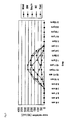
- Fig.3 is a graph showing an example of solar radiation data of January in London.
- the luminosity control of backlight of the liquid crystal display apparatus The horizontal axis means time and the vertical axis means the amount of solar radiation per an hour.
- Fig.1 shows a block diagram of the crystal display apparatus.
- the liquid crystal display 10 has a picture signal input unit 1, a display controller 2, an illumination sensor 3, a real-time clock 4, a microcomputer unit 5, a luminosity controller 6, a backlight 7, and a liquid crystal display unit 8.
- the picture signal input unit 1 is connected to LAN (Local Area Network) for example, and a picture signal is input via LAN, and outputs the picture signal in DVI (Digital Visual Interface) format.
- the display controller 2 converts a picture signal input from the unit 1 into suitable format for the liquid crystal display unit 8, and outputs the converted signal to the unit 8, and an image is displayed in the unit 8.
- the backlight 7 irradiates a light from the back side of the liquid crystal display unit 8 so that the unit can display an image, and is consisted by CCFL (Cold Cathode Fluorescent Lamp) for example.
- the microcomputer unit 5 outputs the backlight control signal indicating the luminosity of the backlight 7 to the luminosity controller 6.
- the controller 6 outputs the PWM (Pulse Width Modulation) driving signal based on the control signal from the unit 5 to the backlight 7.
- the backlight 7 emits a light according to the PWM driving signal from the controller 6.
- the illumination sensor 3 is connected to the microcomputer unit 5, and when the sensor 3 detects sunlight, it outputs an illumination detection signal to the unit 5. Then the microcomputer unit 5 acquires illumination information by A/D conversion of the detection signal from the sensor 3.
- the sensor 3 is arranged in the display surface side of the display unit 8, for example.
- the real-time clock 4 is connected to the microcomputer unit 5 as well, and the unit 5 acquires time information (i.e. date, month, and time) from the clock 4.
- time information i.e. date, month, and time
- a process shown by the flow chart of Fig. 2 is performed periodically.
- the microcomputer unit 5 acquires time information from the real-time clock 4 (step S1).
- the microcomputer unit 5 determines whether the acquired time is within the range of time A shown in Table 1 (step S2).
- Table 1 shows a time range configured for each month which is determined based on the meteorological data of the installing place.
- Time range A is daytime period, for example, and the luminosity of the backlight 7 is controlled between 100% and 60%. In other words, the output of the backlight is controlled between 100% and 60% of the rated output or the maximum output during this time period.
- Time range B is dawn time or sunset time, for example, and the luminosity of the backlight 7 is controlled between 80% and 40%. In other words, the output of the backlight is controlled between 80% and 60% of the rated output or the maximum output during this time period.
- Time range C is nighttime, for example, and the luminosity of the backlight 7 is controlled at 25%. In other words, the output of the backlight is fixed at 25% of the rated output or the maximum output during this time period. In this case, the table is based on the meteorological data of London.
- Fig. 3 is a graph showing the example of the solar radiation data in January in London.
- the horizontal axis means time and the vertical axis means the amount of solar radiation per an hour.
- the data is an average radiation between years 1996 and 2000.
- the luminosity control range of the backlight in January is set between 100% and 60% during time range A (from 9am to 4pm).
- An hour period before and after the time range A, i.e. 8 am to 9am and 4pm to 5 pm are dawn time and sunset time respectively, and since the circumference is presumably bright, the luminosity of the backlight is set between 80% and 40% during this time.
- time except above time range A and B i.e. time range c
- the luminosity of the backlight is fixed to 25%.
- step S2 the microcomputer unit 5 determines the luminosity control range of the backlight 7 between 100% and 60%, then proceeds to Step S5.
- step S5 the microcomputer unit 5 acquires illumination information based on the illumination detection signal from the illumination sensor 3.
- the microcomputer unit 5 determines whether the acquired illumination belongs to the high level range among the level ranges of high, middle, and low.
- step S8 the microcomputer unit 5 outputs the backlight control signal to the luminosity controller 6 so that the luminosity of the backlight gradually changes from the current luminosity to 100% luminosity, which is the maximum of the luminosity range during the time range A period,.
- the luminosity of the backlight 7 changes from the current luminosity to 100%. If current luminosity is already 100%, the microcomputer unit 5 does not output the backlight control signal, thus 100% luminosity is maintained.
- step S7 the microcomputer unit 5 determines whether the acquired illumination belongs to the middle level range. When it is determined that it belongs to the middle level range (i.e. "yes” in step S7), then in step S9, the microcomputer unit 5 outputs the backlight control signal to the luminosity controller 6 so that the luminosity gradually changes from the current luminosity to 80% luminosity, which is the average of the luminosity range in the time range B period. If current luminosity is already 80%, the microcomputer unit 5 does not output the backlight control signal, thus the 80% luminosity is maintained.
- step S10 the microcomputer unit 5 outputs the backlight control signal to the luminosity controller 6 so that the luminosity gradually changes from the current luminosity to 60% luminosity, which is the minimum of the luminosity range during the time period A. If current luminosity is already 60%, the microcomputer unit 5 does not output the backlight control signal, thus the 60% luminosity is maintained.
- step S3 the microcomputer unit 5 determines whether the time is within the time range B. If the time is within the range B, the microcomputer unit 5 determines the luminosity control range of the backlight 7 to be between 80% and 40%, then proceeds to step S11.
- step S11 the microcomputer unit 5 acquires illumination information based on the illumination detection signal from the illumination sensor 3.
- the microcomputer unit 5 determines whether the acquired illumination belongs to the high level range among the level ranges of high, middle, and low. If the illumination belongs to high range (i.e. "yes" in step S12), then in step S14, the microcomputer unit 5 outputs the backlight control signal to the luminosity controller 6 so that the luminosity gradually changes to 80% luminosity, which is the maximum of the luminosity control range in time range B, from the current luminosity.
- a PWM drive signal from the luminosity controller 6 the luminosity of the backlight 7 changes to 80% luminosity from the current luminosity. If current luminosity is already 80%, the microcomputer unit 5 does not output the backlight control signal, thus the 80% luminosity is maintained.
- step S13 the microcomputer unit 5 judges whether the acquired illumination belongs to the middle level range. If the illumination belongs to the middle level range (i.e. "yes” in step S13), then in step S15, the microcomputer unit 5 outputs the backlight control signal to the luminosity controller 6 so that the luminosity gradually changes from the current luminosity to 60% luminosity, which is the average of the luminosity control range in time range B.
- the luminosity controller 6 By a PWM drive signal from the luminosity controller 6, the luminosity of the backlight 7 changes from the current luminosity to 60% luminosity. If current luminosity is already 60%, the microcomputer unit 5 does not output the backlight control signal, thus the 60% luminosity is maintained.
- step S16 the microcomputer unit 5 outputs the backlight control signal to the luminosity controller 6 so that the luminosity gradually changes from the current luminosity to 40% luminosity, which is the minimum of the luminosity range in time range B.
- the luminosity controller 6 By a PWM drive signal from the luminosity controller 6, the luminosity of the backlight 7 changes from the current luminosity to 40% luminosity. If current luminosity is already 40%, the microcomputer unit 5 does not output the backlight control signal, thus the 40% luminosity is maintained.
- step S4 the microcomputer unit 5 outputs the backlight control signal to the luminosity controller 6 so that the luminosity gradually changes from the current luminosity to 25% luminosity.
- the luminosity of the backlight 7 changes from the current luminosity to 25% luminosity. If current luminosity is already 25%, the microcomputer unit 5 does not output the backlight control signal, thus the 25% luminosity is maintained.
- the luminosity is set to 100% according to step S8. If the illumination is fairly high though there is no direct sunlight, the luminosity is set to 80% according to step S9. If the luminosity is low because of cloudy or rainy weathers, the luminosity is set to 60% according to step S10. In this time range, the luminosity control range is limited to 40% in maximum, and accordingly persons looking at the liquid crystal display may not feel uncomfortable. Further, the luminosity can be changed relatively quick. The same applies to the case when vehicles, such as a bus, stops in front of a liquid crystal display frequently.
- step S10 when it is dark all day long (like a rainy day), the luminosity changes gradually, such as 60% in daytime (step S10), 40% in evening (step S16), and 25% in nighttime (step S4), and accordingly persons watching the displays may not feel uncomfortable.
- the average illumination in a predetermined time may be acquired instead.
- the microcomputer unit 5 may keep on sampling the detection signal from the illumination sensor 3 every second, compute an average illumination in a span of 100 seconds, update the illumination information to the computed average illumination, and acquire the updated information in steps S5 or S11. Thereby, an influence from momentum environmental change (i.e. crossing of vehicles in front of the liquid crystal display 10) can be suppressed.
- a direction sensor may be set on the liquid crystal display 10, and procedure of the Fig.2 may be done after the microcomputer unit 5 recognizes the installation direction of the liquid crystal display 10 according to the detection signal from the direction sensor.
- Table 2 may be used in steps S2 and S3 instead of Table 1.
- Table 3 may be used instead of Table 1.
- Table 4 may be used instead of Table 4.
- Table 5 may be used.
- Table 2 to 5 shows a relationship between the time and luminosity control range of the backlight 7, when direction is west, south, east, and north respectively, and is based on the meteorological data of London.
- luminosity can be controlled adequately according to the installation direction of the liquid crystal display 10, and thus the visibility improves.
- the direction information may be set to microcomputer unit 5 manually from an external server via LAN (Local Area Network), or from the controller equipped with the liquid crystal display 10.
- the microcomputer unit 5 may recognize a direction, based on a stored the solar radiation data acquired from the illumination sensor 3. For example, as shown in Fig. 3 , the microcomputer unit 5 may store the solar radiation data acquired from the illumination sensor 3 every hour, compute an average difference between the standard and the stored solar radiation data for each direction (i.e. north, south, east and west), and recognize the direction of the liquid crystal display 10 based on the minimum computed average.
- Table 1 used in procedure of Fig. 2 is assumed to be constant. Instead, data in Table 1 may be updated according to the data stored in the microcomputer unit 5 which is acquired every hour from the illumination sensor 3. Thereby, the luminosity can be set adequately, according to the installation environment of the liquid crystal display 10, and thus the visibility improves.
- the installing area information may be input to the microcomputer unit 5 either from the GPS (Global Position Sensing) installed in liquid crystal display, or by manually, and procedure shown in Fig.2 may be achieved by using tables (like Table 1 to 5) which is set each installing area.
- the microcomputer unit 5 has a relational data between the time and the luminosity control range for every installation area.
- the present invention is applicable not only to liquid crystal displays but also to self emitting type displays such as plasma displays, or organic electroluminescence displays.
Landscapes
- Engineering & Computer Science (AREA)
- Physics & Mathematics (AREA)
- Computer Hardware Design (AREA)
- General Physics & Mathematics (AREA)
- Theoretical Computer Science (AREA)
- Liquid Crystal Display Device Control (AREA)
- Circuit Arrangement For Electric Light Sources In General (AREA)
- Control Of Indicators Other Than Cathode Ray Tubes (AREA)
- Controls And Circuits For Display Device (AREA)
Abstract
Description
- The priority application number
2009-022924 upon which this patent application is based is hereby incorporated by reference. - The present invention relates to a display apparatus.
- In recent years, display apparatus which can be installed outdoors are proposed. In particular, the liquid crystal displays having a flat screen and high resolution are proposed as candidate. However, to install these displays outdoors, it is necessary to consider the environmental factors.
- For example, in order to confront strong sunlight, it is necessary to make display portion of the liquid crystal display brighter. However, if luminosity of its backlight is kept, the power consumption becomes large. Moreover the luminosity may be too high and it may make persons feel dazzling.
- Therefore, level of the backlight may be changed according to the quantity of the sunlight received by a sensor placed at the surface side of the panel. For example, level of the backlight may be risen when the received sunlight is large, and the level may be reduced when the received sunlight is small.
- However, according to the above method, it may give persons sense of discomfort when the level of the backlight changes rapidly due to the rapid change of the received sunlight. For example, if the trucks or buses stop in front of the display frequently, the display gets shadowed frequently as well. And thus the level of the backlight changes frequently, and may give persons sense of discomfort.
- In order to alleviate such discomforts, it might be effective to make the tracking of the backlight slower against the received sunlight. However, sometimes it may take too long before the display becomes viewable for persons.
- A display apparatus of present invention has an illumination acquisition part acquiring the illumination of outdoor daylight, a time acquisition part acquiring date and/or time, a control part controlling display luminosity according to the output of the illumination acquisition part, wherein the control part is characterized by determining the control range of a display luminosity based on the date and/or time the time acquisition part acquired.
-
Fig.1 is a block diagram of a liquid crystal display apparatus. -
Fig.2 is a flow chart showing the luminosity control of backlight of the liquid crystal display apparatus. -
Fig.3 is a graph showing an example of solar radiation data of January in London. The luminosity control of backlight of the liquid crystal display apparatus. The horizontal axis means time and the vertical axis means the amount of solar radiation per an hour. - The present invention embodied in a crystal display apparatus will be specifically described below with the reference to the drawings.
Fig.1 shows a block diagram of the crystal display apparatus. - As shown in
Fig. 1 , theliquid crystal display 10 has a picture signal input unit 1, a display controller 2, anillumination sensor 3, a real-time clock 4, amicrocomputer unit 5, aluminosity controller 6, a backlight 7, and a liquidcrystal display unit 8. - The picture signal input unit 1 is connected to LAN (Local Area Network) for example, and a picture signal is input via LAN, and outputs the picture signal in DVI (Digital Visual Interface) format. The display controller 2 converts a picture signal input from the unit 1 into suitable format for the liquid
crystal display unit 8, and outputs the converted signal to theunit 8, and an image is displayed in theunit 8. - The backlight 7 irradiates a light from the back side of the liquid
crystal display unit 8 so that the unit can display an image, and is consisted by CCFL (Cold Cathode Fluorescent Lamp) for example. Themicrocomputer unit 5 outputs the backlight control signal indicating the luminosity of the backlight 7 to theluminosity controller 6. Thecontroller 6 outputs the PWM (Pulse Width Modulation) driving signal based on the control signal from theunit 5 to the backlight 7. The backlight 7 emits a light according to the PWM driving signal from thecontroller 6. - The
illumination sensor 3 is connected to themicrocomputer unit 5, and when thesensor 3 detects sunlight, it outputs an illumination detection signal to theunit 5. Then themicrocomputer unit 5 acquires illumination information by A/D conversion of the detection signal from thesensor 3. Thesensor 3 is arranged in the display surface side of thedisplay unit 8, for example. - The real-
time clock 4 is connected to themicrocomputer unit 5 as well, and theunit 5 acquires time information (i.e. date, month, and time) from theclock 4. - Hereafter, a luminosity control of the backlight 7 in the
liquid crystal display 10 is explained using a flow chart shown inFig. 2 . - A process shown by the flow chart of
Fig. 2 is performed periodically. First, themicrocomputer unit 5 acquires time information from the real-time clock 4 (step S1). Themicrocomputer unit 5 then determines whether the acquired time is within the range of time A shown in Table 1 (step S2).Table 1 Time Range A Time Range B Time Range C January 9am to 4pm 8am to 9am or 4pm to 5pm Otherwise February 8am to 5pm 7am to 8am or 5pm to 6pm Otherwise March 7am to 6pm 6am to 7am or 6pm to 7pm Otherwise April 7am to 7pm 6am to 7am or 7pm to 8pm Otherwise May 6am to 8pm 5am to 6am or 8pm to 9pm Otherwise June 6am to 8pm 5am to 6am or 8pm to 9pm Otherwise July 6am to 8pm 5am to 6am or 8pm to 9pm Otherwise August 6am to 8pm 5am to 6am or 8pm to 9pm Otherwise September 7am to 7pm 6am to 7am or 7pm to 8pm Otherwise October 8am to 5pm 7am to 8am or 5pm to 6pm Otherwise November 8am to 4pm 7am to 8am or 4pm to 5pm Otherwise December 9am to 3pm 8am to 9am or 3pm to 4pm Otherwise - Table 1 shows a time range configured for each month which is determined based on the meteorological data of the installing place. Time range A is daytime period, for example, and the luminosity of the backlight 7 is controlled between 100% and 60%. In other words, the output of the backlight is controlled between 100% and 60% of the rated output or the maximum output during this time period. Time range B is dawn time or sunset time, for example, and the luminosity of the backlight 7 is controlled between 80% and 40%. In other words, the output of the backlight is controlled between 80% and 60% of the rated output or the maximum output during this time period. Time range C is nighttime, for example, and the luminosity of the backlight 7 is controlled at 25%. In other words, the output of the backlight is fixed at 25% of the rated output or the maximum output during this time period. In this case, the table is based on the meteorological data of London.
-
Fig. 3 is a graph showing the example of the solar radiation data in January in London. The horizontal axis means time and the vertical axis means the amount of solar radiation per an hour. Here, the data is an average radiation between years 1996 and 2000. According toFig.3 , from 9 am to 4 pm, since the radiation may exceed 100 [W/m2] depending on a direction, the luminosity control range of the backlight in January is set between 100% and 60% during time range A (from 9am to 4pm). An hour period before and after the time range A, i.e. 8 am to 9am and 4pm to 5 pm are dawn time and sunset time respectively, and since the circumference is presumably bright, the luminosity of the backlight is set between 80% and 40% during this time. During the time except above time range A and B (i.e. time range c), since it is presumably a nighttime, the luminosity of the backlight is fixed to 25%. - When it is determined that the acquired time is within the time range A (i.e. "yes" in step S2), the
microcomputer unit 5 determines the luminosity control range of the backlight 7 between 100% and 60%, then proceeds to Step S5. - In step S5, the
microcomputer unit 5 acquires illumination information based on the illumination detection signal from theillumination sensor 3. Themicrocomputer unit 5 then determines whether the acquired illumination belongs to the high level range among the level ranges of high, middle, and low. When it is determined that it belongs to the high range (i.e. "yes" in step S6), then in step S8, themicrocomputer unit 5 outputs the backlight control signal to theluminosity controller 6 so that the luminosity of the backlight gradually changes from the current luminosity to 100% luminosity, which is the maximum of the luminosity range during the time range A period,. By a PWM drive signal from theluminosity controller 6, the luminosity of the backlight 7 changes from the current luminosity to 100%. If current luminosity is already 100%, themicrocomputer unit 5 does not output the backlight control signal, thus 100% luminosity is maintained. - When it is determined that the acquired illumination does not belong to the high level range (i.e. "no" in step S6), then in step S7, the
microcomputer unit 5 determines whether the acquired illumination belongs to the middle level range. When it is determined that it belongs to the middle level range (i.e. "yes" in step S7), then in step S9, themicrocomputer unit 5 outputs the backlight control signal to theluminosity controller 6 so that the luminosity gradually changes from the current luminosity to 80% luminosity, which is the average of the luminosity range in the time range B period. If current luminosity is already 80%, themicrocomputer unit 5 does not output the backlight control signal, thus the 80% luminosity is maintained. - When it is determined that the acquired illumination does not belong to the middle level range (i.e. "no" in step S7), then in step S10, the
microcomputer unit 5 outputs the backlight control signal to theluminosity controller 6 so that the luminosity gradually changes from the current luminosity to 60% luminosity, which is the minimum of the luminosity range during the time period A. If current luminosity is already 60%, themicrocomputer unit 5 does not output the backlight control signal, thus the 60% luminosity is maintained. - When it is determined that the acquired time is not within the time range A (i.e. "no" in step S2), then in step S3, the
microcomputer unit 5 determines whether the time is within the time range B. If the time is within the range B, themicrocomputer unit 5 determines the luminosity control range of the backlight 7 to be between 80% and 40%, then proceeds to step S11. - In step S11, the
microcomputer unit 5 acquires illumination information based on the illumination detection signal from theillumination sensor 3. Themicrocomputer unit 5 then determines whether the acquired illumination belongs to the high level range among the level ranges of high, middle, and low. If the illumination belongs to high range (i.e. "yes" in step S12), then in step S14, themicrocomputer unit 5 outputs the backlight control signal to theluminosity controller 6 so that the luminosity gradually changes to 80% luminosity, which is the maximum of the luminosity control range in time range B, from the current luminosity. By a PWM drive signal from theluminosity controller 6, the luminosity of the backlight 7 changes to 80% luminosity from the current luminosity. If current luminosity is already 80%, themicrocomputer unit 5 does not output the backlight control signal, thus the 80% luminosity is maintained. - When it is determined that the acquired illumination does not belong to the high level range (i.e. "no" in step S12), then in step S13, the
microcomputer unit 5 judges whether the acquired illumination belongs to the middle level range. If the illumination belongs to the middle level range (i.e. "yes" in step S13), then in step S15, themicrocomputer unit 5 outputs the backlight control signal to theluminosity controller 6 so that the luminosity gradually changes from the current luminosity to 60% luminosity, which is the average of the luminosity control range in time range B. By a PWM drive signal from theluminosity controller 6, the luminosity of the backlight 7 changes from the current luminosity to 60% luminosity. If current luminosity is already 60%, themicrocomputer unit 5 does not output the backlight control signal, thus the 60% luminosity is maintained. - When it is determined that the acquired illumination does not belong to the middle level range (i.e. "no" in step S13), then in step S16, the
microcomputer unit 5 outputs the backlight control signal to theluminosity controller 6 so that the luminosity gradually changes from the current luminosity to 40% luminosity, which is the minimum of the luminosity range in time range B. By a PWM drive signal from theluminosity controller 6, the luminosity of the backlight 7 changes from the current luminosity to 40% luminosity. If current luminosity is already 40%, themicrocomputer unit 5 does not output the backlight control signal, thus the 40% luminosity is maintained. - When it is determined that the acquired time is not within the time range B (i.e. "no" in step S3), then in step S4, the
microcomputer unit 5 outputs the backlight control signal to theluminosity controller 6 so that the luminosity gradually changes from the current luminosity to 25% luminosity. By a PWM drive signal from theluminosity controller 6, the luminosity of the backlight 7 changes from the current luminosity to 25% luminosity. If current luminosity is already 25%, themicrocomputer unit 5 does not output the backlight control signal, thus the 25% luminosity is maintained. - For example, in time range between 9am to 16pm in January, if the illumination is high because of the direct sunlight, the luminosity is set to 100% according to step S8. If the illumination is fairly high though there is no direct sunlight, the luminosity is set to 80% according to step S9. If the luminosity is low because of cloudy or rainy weathers, the luminosity is set to 60% according to step S10. In this time range, the luminosity control range is limited to 40% in maximum, and accordingly persons looking at the liquid crystal display may not feel uncomfortable. Further, the luminosity can be changed relatively quick. The same applies to the case when vehicles, such as a bus, stops in front of a liquid crystal display frequently. Further, when it is dark all day long (like a rainy day), the luminosity changes gradually, such as 60% in daytime (step S10), 40% in evening (step S16), and 25% in nighttime (step S4), and accordingly persons watching the displays may not feel uncomfortable.
- The reason why the luminosity is changed in three steps depending on the illumination information, rather than using proportionality function between the illumination and the luminosity in a procedure shown in
Fig. 2 , is that a frequent change of luminosity makes persons looking at liquid crystal displays uncomfortable. Thereby the frequent change is suppressed. - In steps S5 and S11 of
Fig.2 , though a momentary illumination at the time is acquired, the average illumination in a predetermined time may be acquired instead. For example, themicrocomputer unit 5 may keep on sampling the detection signal from theillumination sensor 3 every second, compute an average illumination in a span of 100 seconds, update the illumination information to the computed average illumination, and acquire the updated information in steps S5 or S11. Thereby, an influence from momentum environmental change (i.e. crossing of vehicles in front of the liquid crystal display 10) can be suppressed. - Following modification may be applied to the embodiment of the present invention.
- For example, a direction sensor may be set on the
liquid crystal display 10, and procedure of theFig.2 may be done after themicrocomputer unit 5 recognizes the installation direction of theliquid crystal display 10 according to the detection signal from the direction sensor. If the direction recognized by the sensor is west, Table 2 may be used in steps S2 and S3 instead of Table 1. If the direction is south, Table 3 may be used instead. If the direction is east, Table 4 may be used. If the direction is north, Table 5 may be used. Here, Table 2 to 5 shows a relationship between the time and luminosity control range of the backlight 7, when direction is west, south, east, and north respectively, and is based on the meteorological data of London.Table 2 Time Range A Time Range B Time Range C 100% to 60% 80% to 40% Fixed to 25% January 1pm to 3pm 9am to 1pm or 3pm to 5pm Otherwise February 1pm to 4pm 8am to 1pm or 4pm to 5pm Otherwise March 12pm to 5pm 7am to 12pm or 5pm to 7pm Otherwise April 11am to 7pm 7am to 11am or 7pm to 8pm Otherwise May 10am to 8pm 6am to 10am or 8pm to 9pm Otherwise June 9am to 8pm 5am to 9am or 8pm to 9pm Otherwise July 9am to 8pm 6am to 9am or 8pm to 9pm Otherwise August 10am to 8pm 6am to 10am or 8pm to 9pm Otherwise September 11am to 7pm 7am to 11am or 7pm to 8pm Otherwise October 1pm to 5pm 8am to 1pm or 5pm to 6pm Otherwise November 1pm to 3pm 8am to 1pm or 3pm to 4pm Otherwise December 1pm to 2pm 9am to 1pm or 2pm to 4pm Otherwise Table 3 Time Range A Time Range B Time Range C 100% to 60% 80% to 40% Fixed to 25% January 9am to 4pm 8am to 9am or 3pm to 5pm Otherwise February 8am to 4pm 7am to 8am or 4pm to 5pm Otherwise March 8am to 4pm 6am to 8am or 5pm to 6pm Otherwise April 8am to 5pm 7am to 8am or 5pm to 7pm Otherwise May 8am to 5pm 6am to 8am or 5pm to 8pm Otherwise June 8am to 5pm 5am to 8am or 5pm to 8pm Otherwise July 8am to 6pm 6am to 8am or 6pm to 9pm Otherwise August 8am to 6pm 6am to 8am or 6pm to 8pm Otherwise September 8am to 5pm 7am to 8am or 5pm to 7pm Otherwise October 8am to 5pm 7am to 8am or 5pm to 6pm Otherwise November 8am to 3pm 7am to 8am or 3pm to 4pm Otherwise December 9am to 3pm 8am to 9am or 3pm to 4pm Otherwise Table 4 Time Range A Time Range B Time Range C 100% to 60% 80% to 40% Fixed to 25% January 9am to 11am 8am to 9am or 11am to 4pm Otherwise February 8am to 12pm 7am to 8am or 12pm to 5pm Otherwise March 7am to 12pm 6am to 7am or 12pm to 6pm Otherwise April 7am to 3pm 6am to 7am or 3pm to 7pm Otherwise May 6am to 4pm 5am to 6am or 4pm to 8pm Otherwise June 6am to 5pm 5am to 6am or 5pm to 9pm Otherwise July 6am to 5pm 5am to 6am or 5pm to 9pm Otherwise August 6am to 4pm 5am to 6am or 4pm to 8pm Otherwise September 7am to 2pm 6am to 7am or 2pm to 7pm Otherwise October 8am to 12pm 7am to 8am or 12pm to 6pm Otherwise November 8am to 11am 7am to 8am or 11am to 4pm Otherwise December 9am to 11am 8am to 9am or 11am to 3pm Otherwise Table 5 Time Range A Time Range B Time Range C 100% to 60% 80% to 40% Fixed to 25% January - 8am to 5pm Otherwise February - 7am to 6pm Otherwise March - 6am to 7pm Otherwise April - 6am to 8pm Otherwise May - 5am to 9pm Otherwise June - 5am to 9pm Otherwise July - 5am to 9pm Otherwise August - 5am to 9pm Otherwise September - 6am to 8pm Otherwise October - 7am to 6pm Otherwise November - 7am to 5pm Otherwise December - 8am to 4pm Otherwise - According to this modified embodiment, luminosity can be controlled adequately according to the installation direction of the
liquid crystal display 10, and thus the visibility improves. The direction information may be set tomicrocomputer unit 5 manually from an external server via LAN (Local Area Network), or from the controller equipped with theliquid crystal display 10. - Further, the
microcomputer unit 5 may recognize a direction, based on a stored the solar radiation data acquired from theillumination sensor 3. For example, as shown inFig. 3 , themicrocomputer unit 5 may store the solar radiation data acquired from theillumination sensor 3 every hour, compute an average difference between the standard and the stored solar radiation data for each direction (i.e. north, south, east and west), and recognize the direction of theliquid crystal display 10 based on the minimum computed average. - In above-mentioned embodiment, Table 1 used in procedure of
Fig. 2 is assumed to be constant. Instead, data in Table 1 may be updated according to the data stored in themicrocomputer unit 5 which is acquired every hour from theillumination sensor 3. Thereby, the luminosity can be set adequately, according to the installation environment of theliquid crystal display 10, and thus the visibility improves. - The present invention is not limited to the foregoing embodiment but can be modified variously by one skilled in the art without departing from the spirit of the invention as set forth in the appended claims.
- For example, the installing area information may be input to the
microcomputer unit 5 either from the GPS (Global Position Sensing) installed in liquid crystal display, or by manually, and procedure shown inFig.2 may be achieved by using tables (like Table 1 to 5) which is set each installing area. In this case, themicrocomputer unit 5 has a relational data between the time and the luminosity control range for every installation area. - Moreover, the present invention is applicable not only to liquid crystal displays but also to self emitting type displays such as plasma displays, or organic electroluminescence displays.
Claims (3)
- A display apparatus, comprising:an illumination acquisition part acquiring the illumination of outdoor daylight,a time acquisition part acquiring date and/or time,a control part controlling display luminosity according to the output of the illumination acquisition part, whereinthe control part is characterized by determining the control range of a display luminosity based on the date and/or time the time acquisition part acquired.
- A display apparatus according to claim 1, wherein
the control part recognizes the installation direction of the display and determines the controlling range of display luminosity based on the recognized installation direction. - A display apparatus according to claim 1, wherein
the control part stores the solar radiation data based on the output of the illumination acquisition part, and determines the control range of display luminosity based on the stored data.
Applications Claiming Priority (1)
| Application Number | Priority Date | Filing Date | Title |
|---|---|---|---|
| JP2009022924A JP2010181487A (en) | 2009-02-03 | 2009-02-03 | Display device |
Publications (1)
| Publication Number | Publication Date |
|---|---|
| EP2214155A1 true EP2214155A1 (en) | 2010-08-04 |
Family
ID=42215814
Family Applications (1)
| Application Number | Title | Priority Date | Filing Date |
|---|---|---|---|
| EP10001068A Withdrawn EP2214155A1 (en) | 2009-02-03 | 2010-02-02 | Display apparatus |
Country Status (3)
| Country | Link |
|---|---|
| US (1) | US20100194725A1 (en) |
| EP (1) | EP2214155A1 (en) |
| JP (1) | JP2010181487A (en) |
Cited By (1)
| Publication number | Priority date | Publication date | Assignee | Title |
|---|---|---|---|---|
| CN106205557A (en) * | 2016-09-29 | 2016-12-07 | 北京小米移动软件有限公司 | Screen brightness regulation method and device |
Families Citing this family (15)
| Publication number | Priority date | Publication date | Assignee | Title |
|---|---|---|---|---|
| JP2012118130A (en) * | 2010-11-29 | 2012-06-21 | Sanyo Electric Co Ltd | Display device and electronic apparatus |
| KR102047433B1 (en) | 2011-09-23 | 2019-12-04 | 매뉴팩처링 리소시스 인터내셔널 인코포레이티드 | System and method for environmental adaptation of display characteristics |
| KR102081931B1 (en) * | 2013-06-19 | 2020-02-26 | 엘지전자 주식회사 | Foldable display device and method for controlling thereof |
| CN105810152B (en) * | 2014-12-29 | 2018-06-19 | Tcl海外电子(惠州)有限公司 | Method for controlling backlight thereof and device, the television set of display terminal |
| US10607520B2 (en) | 2015-05-14 | 2020-03-31 | Manufacturing Resources International, Inc. | Method for environmental adaptation of display characteristics based on location |
| US10593255B2 (en) | 2015-05-14 | 2020-03-17 | Manufacturing Resources International, Inc. | Electronic display with environmental adaptation of display characteristics based on location |
| US9924583B2 (en) | 2015-05-14 | 2018-03-20 | Mnaufacturing Resources International, Inc. | Display brightness control based on location data |
| KR102130667B1 (en) * | 2015-08-17 | 2020-07-06 | 매뉴팩처링 리소시스 인터내셔널 인코포레이티드 | Electronic display with environmental adaptation of location-based display characteristics |
| US10578658B2 (en) | 2018-05-07 | 2020-03-03 | Manufacturing Resources International, Inc. | System and method for measuring power consumption of an electronic display assembly |
| WO2019241546A1 (en) | 2018-06-14 | 2019-12-19 | Manufacturing Resources International, Inc. | System and method for detecting gas recirculation or airway occlusion |
| KR102579688B1 (en) | 2018-12-24 | 2023-09-19 | 삼성전자주식회사 | Electronic apparatus and controlling method thereof |
| US11526044B2 (en) | 2020-03-27 | 2022-12-13 | Manufacturing Resources International, Inc. | Display unit with orientation based operation |
| US12105370B2 (en) | 2021-03-15 | 2024-10-01 | Manufacturing Resources International, Inc. | Fan control for electronic display assemblies |
| KR20230154964A (en) | 2021-03-15 | 2023-11-09 | 매뉴팩처링 리소시스 인터내셔널 인코포레이티드 | Fan control for electronic display assemblies |
| US12027132B1 (en) | 2023-06-27 | 2024-07-02 | Manufacturing Resources International, Inc. | Display units with automated power governing |
Citations (6)
| Publication number | Priority date | Publication date | Assignee | Title |
|---|---|---|---|---|
| GB2327315A (en) * | 1997-06-18 | 1999-01-20 | Samsung Electronics Co Ltd | Device and method for controlling illumination of a telephone keypad by measurement of ambient light level |
| WO2002076068A1 (en) * | 2000-12-21 | 2002-09-26 | Qualcomm Incorporated | System and method for backlighting control in a wireless communication device |
| WO2006048393A2 (en) * | 2004-11-02 | 2006-05-11 | Thomson Licensing | Time display device |
| US20060209096A1 (en) * | 2005-03-18 | 2006-09-21 | Yu-Chien Huang | Display mode control method for an electronic device |
| US20070115209A1 (en) * | 2005-11-24 | 2007-05-24 | Denso Corporation | Luminance control apparatus for light emitting device |
| WO2009022924A1 (en) | 2007-08-15 | 2009-02-19 | William Bryan Woodard | Image generation system |
Family Cites Families (2)
| Publication number | Priority date | Publication date | Assignee | Title |
|---|---|---|---|---|
| US7627330B2 (en) * | 2005-01-31 | 2009-12-01 | Research In Motion Limited | Mobile electronic device having a geographical position dependent light and method and system for achieving the same |
| US7973779B2 (en) * | 2007-10-26 | 2011-07-05 | Microsoft Corporation | Detecting ambient light levels in a vision system |
-
2009
- 2009-02-03 JP JP2009022924A patent/JP2010181487A/en not_active Withdrawn
-
2010
- 2010-02-02 EP EP10001068A patent/EP2214155A1/en not_active Withdrawn
- 2010-02-03 US US12/699,381 patent/US20100194725A1/en not_active Abandoned
Patent Citations (6)
| Publication number | Priority date | Publication date | Assignee | Title |
|---|---|---|---|---|
| GB2327315A (en) * | 1997-06-18 | 1999-01-20 | Samsung Electronics Co Ltd | Device and method for controlling illumination of a telephone keypad by measurement of ambient light level |
| WO2002076068A1 (en) * | 2000-12-21 | 2002-09-26 | Qualcomm Incorporated | System and method for backlighting control in a wireless communication device |
| WO2006048393A2 (en) * | 2004-11-02 | 2006-05-11 | Thomson Licensing | Time display device |
| US20060209096A1 (en) * | 2005-03-18 | 2006-09-21 | Yu-Chien Huang | Display mode control method for an electronic device |
| US20070115209A1 (en) * | 2005-11-24 | 2007-05-24 | Denso Corporation | Luminance control apparatus for light emitting device |
| WO2009022924A1 (en) | 2007-08-15 | 2009-02-19 | William Bryan Woodard | Image generation system |
Cited By (4)
| Publication number | Priority date | Publication date | Assignee | Title |
|---|---|---|---|---|
| CN106205557A (en) * | 2016-09-29 | 2016-12-07 | 北京小米移动软件有限公司 | Screen brightness regulation method and device |
| EP3301664A3 (en) * | 2016-09-29 | 2018-06-13 | Beijing Xiaomi Mobile Software Co., Ltd. | Method and apparatus for adjusting screen brightness |
| US10204595B2 (en) | 2016-09-29 | 2019-02-12 | Beijing Xiaomi Mobile Software Co., Ltd. | Methods and devices for adjusting screen brightness |
| CN106205557B (en) * | 2016-09-29 | 2019-08-02 | 北京小米移动软件有限公司 | Screen brightness regulation method and device |
Also Published As
| Publication number | Publication date |
|---|---|
| US20100194725A1 (en) | 2010-08-05 |
| JP2010181487A (en) | 2010-08-19 |
Similar Documents
| Publication | Publication Date | Title |
|---|---|---|
| US20100194725A1 (en) | Display Apparatus | |
| US20140303788A1 (en) | Dynamic façade system consisting of controllable windows, automated shades and dimmable electric lights | |
| US8890798B2 (en) | Backlight control of electronic device | |
| EP2216769B1 (en) | Display device and display system | |
| CN101630484B (en) | Backlight controller, display device using the same and control method of backlight module | |
| US8698732B2 (en) | Outdoor display system and display apparatus | |
| US11830445B2 (en) | System, information processing apparatus, and non-transitory storage medium | |
| CN105118434B (en) | Display screen adjusts display optimization method at times | |
| EP1964098A2 (en) | Adjusting the refresh rate of a display | |
| US20190172411A1 (en) | Visual display system and method | |
| US20140362281A1 (en) | Exposure control device, imaging device, image display device, and exposure control method | |
| US20120139888A1 (en) | Display system | |
| CN109036331A (en) | Brightness adjusting method and device, the display screen of display screen | |
| CN101685148A (en) | Backlight illumination automatic regulation device and method | |
| JP5625463B2 (en) | Image display device, image display system, and illuminance identification method | |
| JP2016170415A (en) | Electronic display adjustment based on gaze tracking | |
| KR101578843B1 (en) | System and method for tuning visual parameter of web page | |
| KR20220099443A (en) | Dynamic brightness change system and method of vehicle display device | |
| CN1855206A (en) | Method for adjusting display device brightness automatically | |
| ES2454869T3 (en) | Procedure for mobile device backlight adjustment | |
| US20080136768A1 (en) | Display apparatus and method for controlling contrast thereof | |
| JP2024124249A (en) | Display device | |
| JP2007043533A (en) | Display device | |
| JP2012042761A (en) | Video display device | |
| JPH08194445A (en) | Microphone device with optical display |
Legal Events
| Date | Code | Title | Description |
|---|---|---|---|
| PUAI | Public reference made under article 153(3) epc to a published international application that has entered the european phase |
Free format text: ORIGINAL CODE: 0009012 |
|
| AK | Designated contracting states |
Kind code of ref document: A1 Designated state(s): AT BE BG CH CY CZ DE DK EE ES FI FR GB GR HR HU IE IS IT LI LT LU LV MC MK MT NL NO PL PT RO SE SI SK SM TR |
|
| AX | Request for extension of the european patent |
Extension state: AL BA RS |
|
| 17P | Request for examination filed |
Effective date: 20101222 |
|
| 17Q | First examination report despatched |
Effective date: 20110401 |
|
| R17C | First examination report despatched (corrected) |
Effective date: 20111024 |
|
| STAA | Information on the status of an ep patent application or granted ep patent |
Free format text: STATUS: THE APPLICATION HAS BEEN WITHDRAWN |
|
| 18W | Application withdrawn |
Effective date: 20120524 |