EP2214006A2 - Pressure device for measuring physical property - Google Patents
Pressure device for measuring physical property Download PDFInfo
- Publication number
- EP2214006A2 EP2214006A2 EP09172173A EP09172173A EP2214006A2 EP 2214006 A2 EP2214006 A2 EP 2214006A2 EP 09172173 A EP09172173 A EP 09172173A EP 09172173 A EP09172173 A EP 09172173A EP 2214006 A2 EP2214006 A2 EP 2214006A2
- Authority
- EP
- European Patent Office
- Prior art keywords
- piston
- inner cylinder
- pressure device
- pressure
- fabricated
- Prior art date
- Legal status (The legal status is an assumption and is not a legal conclusion. Google has not performed a legal analysis and makes no representation as to the accuracy of the status listed.)
- Withdrawn
Links
Images




Classifications
-
- G—PHYSICS
- G01—MEASURING; TESTING
- G01N—INVESTIGATING OR ANALYSING MATERIALS BY DETERMINING THEIR CHEMICAL OR PHYSICAL PROPERTIES
- G01N1/00—Sampling; Preparing specimens for investigation
- G01N1/28—Preparing specimens for investigation including physical details of (bio-)chemical methods covered elsewhere, e.g. G01N33/50, C12Q
- G01N1/286—Preparing specimens for investigation including physical details of (bio-)chemical methods covered elsewhere, e.g. G01N33/50, C12Q involving mechanical work, e.g. chopping, disintegrating, compacting, homogenising
-
- G—PHYSICS
- G01—MEASURING; TESTING
- G01N—INVESTIGATING OR ANALYSING MATERIALS BY DETERMINING THEIR CHEMICAL OR PHYSICAL PROPERTIES
- G01N3/00—Investigating strength properties of solid materials by application of mechanical stress
- G01N3/08—Investigating strength properties of solid materials by application of mechanical stress by applying steady tensile or compressive forces
- G01N3/10—Investigating strength properties of solid materials by application of mechanical stress by applying steady tensile or compressive forces generated by pneumatic or hydraulic pressure
- G01N3/12—Pressure testing
-
- G—PHYSICS
- G01—MEASURING; TESTING
- G01N—INVESTIGATING OR ANALYSING MATERIALS BY DETERMINING THEIR CHEMICAL OR PHYSICAL PROPERTIES
- G01N27/00—Investigating or analysing materials by the use of electric, electrochemical, or magnetic means
-
- G—PHYSICS
- G01—MEASURING; TESTING
- G01N—INVESTIGATING OR ANALYSING MATERIALS BY DETERMINING THEIR CHEMICAL OR PHYSICAL PROPERTIES
- G01N27/00—Investigating or analysing materials by the use of electric, electrochemical, or magnetic means
- G01N27/72—Investigating or analysing materials by the use of electric, electrochemical, or magnetic means by investigating magnetic variables
-
- G—PHYSICS
- G01—MEASURING; TESTING
- G01N—INVESTIGATING OR ANALYSING MATERIALS BY DETERMINING THEIR CHEMICAL OR PHYSICAL PROPERTIES
- G01N33/00—Investigating or analysing materials by specific methods not covered by groups G01N1/00 - G01N31/00
- G01N33/20—Metals
Definitions
- the present invention relates to a pressure device for measuring a physical property, and more particularly, to a pressure device for measuring a physical property that pressurizes a sample with being mounted on a physical property measuring system (PPMS) and investigates a change of the volume and a lattice structure of the pressurized sample and changes of an electrical characteristic and a magnetic characteristic.
- PPMS physical property measuring system
- Pressure devices having various structures and experimental technologies have been developed. Among them, a device that has a sample inside of a cylinder and applies a pressure to the sample by pressurizing the inside of the cylinder with a piston has been known.
- the pressure device must secure high durability under the low-temperature, high-pressure, and high-magnetic field conditions and have a structure in which parts and samples can be easily replaced.
- the sealing member may include i) a sealing cap that is in closed contact with the piston and of which an end opposite to the piston is opened; and ii) a support joined to the end of the sealing cap.
- the sealing cap may be fabricated by polytetrafluoroethylene (PTFE) and the support may be fabricated by the copper-beryllium alloy.
- An outer diameter of the sealing cap is larger than a diameter of the through-hole, such that the sealing cap may press on the through-hole.
- a lubricant containing polytetrafluoroethylene (PTFE) powder may be applied between the sealing cap and the inner cylinder.
- the outer cylinder may have a first flange formed at a pressure applied end thereof and a second flange formed at the other end opposite to the first flange.
- the pressure device for measuring a physical property may further include i) a first locking nut that screw-engages with the inside of the first flange to fix a position of the piston and ii) a second locking nut that screw-engages with the inside of the second flange to fix a position of the sealing member.
- the piston may include i) a first piston joined to the inner cylinder, ii) a pressure transmission pad connected to the first piston in a pressure applied direction, and iii) a second piston connected to the pressure transmission pad in the pressure applied direction.
- the pressure transmission pad may have a width larger than the first and second pistons. At least one of the first piston, the pressure transmission pad, and the second piston may be fabricated by tungsten carbide.
- the pressure device for measuring a physical property may further include i) a lead wire that passes through the sealing member, the fixing member, and the second locking nut, and is electrically connected to the sample; and ii) a protection tube that surrounds the lead wire with an insulating adhesive interposed therebetween.
- the lead wire may be a copper wire and is may be mounted on the protection tube with being twisted.
- the insulating adhesive may be an epoxy-based adhesive.
- the protection tube may be fabricated by any one of a polymer resin, cupro-nickel, and stainless steel.
- the pressure device for measuring a physical property has a dual structure of the inner cylinder and the outer cylinder, it is possible to improve durability by securing high mechanical rigidity.
- the inner cylinder is detachably joined to the outer cylinder, it is possible to easily replace the inner cylinder with an inner cylinder having a different material by separating the inner cylinder from the outer cylinder in accordance with an experimental condition.
- the pressure device can effectively endure a repetitive thermal cycling and perform accurate measurement under a cryogenic high-pressure and high-magnetic field environment.
- FIG. 1 is a perspective view of a pressure device 100 for measuring a physical property according to an exemplary embodiment of the present invention.
- FIG. 2 is a cross-sectional view of a pressure device 100 for measuring a physical property according to an exemplary embodiment of the present invention.
- the structure of the pressure device 100 shown in FIGS. 1 and 2 just exemplifies the present invention, but the present invention is not limited thereto. Therefore, the structure of the pressure device 100 may be modified into other forms.
- the sealing member 10 incorporates a sample 22 which is a measurement target material and a pressure transmission medium 24 surrounding the sample 22.
- the sealing member 10 includes a sealing cap 26 of which a lower end is opened and a support 28 joined to the lower end of the sealing cap 26.
- the sealing cap 26 is directly applied with a pressure from the piston 16. This pressure is transmitted to the sample 22 through the pressure transmission medium 24 and induces changes of electrical and magnetic states by changing the volume and a lattice structure of the sample 22.
- the sealing cap 26 may be fabricated by a polymer resin and the support 28 may be fabricated by a high-rigidity metal.
- the sealing cap 26 may be fabricated by polytetrafluoroethylene (PTFE) having excellent thermal and chemical properties and the support 28 may be fabricated by a copper-beryllium (CuBe) alloy having excellent fatigue-resistant, wear-resistant, and corrosion-resistant properties.
- PTFE polytetrafluoroethylene
- CuBe copper-beryllium
- the inner cylinder 12 and the outer cylinder 14 are detachably joined to each other. Accordingly, the inner cylinder 12 can be easily separated and replaced from the outer cylinder 14 in accordance with experimental conditions.
- a reinforced nickel-chrome-aluminum alloy which is aged at 850°C can increase a maximum pressure which can be achieved by the piston up to 4 GPa at 4.2 K.
- the nickel-chrome-aluminum alloy has an electrical resistance of approximately 90 ⁇ cm at 300 K and an electrical resistance of approximately 50 ⁇ cm at 4.2 K.
- an electrical structure of the nickel-chrome-aluminum alloy is slightly changed by applying a high magnetic field. Accordingly, the outer cylinder 14 fabricated by the nickel-chrome-aluminum alloy can maintain high durability even under the high-magnetic field environment.
- the inner cylinder 12 may be fabricated by the nickel-chrome-aluminum alloy similarly as the outer cylinder 14. Meanwhile, the inner cylinder 12 may be fabricated by a material different from the material of the outer cylinder 14 depending on experimental conditions such as temperature and pressure ranges, etc. For example, the inner cylinder 12 may be fabricated by any one among the copper-beryllium alloy, the maraging steel, and the nickel-cobalt-chrome-molybdenum alloy.
- the first and second pistons 36 and 40 and the pressure transmission pad 38 may be fabricated by the non-magnetic high-rigidity metal, i.e., tungsten carbide.
- the second piston 40 can be directly applied with the pressure from a hydraulic ram (not shown) in close contact with the hydraulic ram. Meanwhile, as shown in FIG. 4 , the second piston 40 is joined to a piston holder 42 to receive the pressure from the hydraulic ram through the piston holder 42.
- the piston holder 42 includes a back-up member 44 connected to an upper end of the second piston 40 and a holder body 46 that surrounds the entirety of the back-up member 44 and a portion of an upper part of the second piston 40.
- the back-up member 44 has a width larger than the second piston 40 and may be fabricated by the same material as the second piston 40.
- the holder body 46 has a width larger than the back-up member 44 and may be fabricated by a different material from the materials of the second piston 40 and the back-up member 44.
- the holder body 46 may be fabricated by stainless steel having high rigidity and corrosion resistance.
- the second locking nut 20 is detachably joined to the inside of the second flange 34.
- a fifth thread 501 may be formed on an inner wall of the second flange 34 and a sixth thread 502 may be formed on an outer wall of the second locking nut 20.
- the second locking nut 20 serves to fix positions of the support 28 and a fixing member 52 by pressing the fixing member 52 connected to the support 28.
- FIG. 6 is a partial cross-sectional view illustrating a state in which the second flange 34 and the second locking nut 20 are separated from each other in the pressure device 100 shown in FIG. 2 .
- the protection tube 56 may be fabricated by the polymer resin or a metal such as cupro-nickel or stainless steel.
- the protection tube 56 prevents a short-circuit between the lead wire 54 and the support 28 at a high pressure of 4.0 GPa and a low temperature of 4K and can effectively secure stability of the lead wire 54.
- the protection tube 56 when the protection tube 56 is fabricated by the metal, the protection tube 56 has conductivity, such that the lead wire 54 and the protection tube 56 must not be in contact with each other.
- the inner and outer cylinders 12 and 14 and the first and second locking nuts 16 and 18 are fabricated by the nickel-chrome-aluminum alloy which is the high-rigidity and non-magnetic metal, such that the pressure device 100 can effectively endure repetitive thermal cycling and perform accurate measurement under a cryogenic high-pressure and high-magnetic field environment.
Landscapes
- Chemical & Material Sciences (AREA)
- Analytical Chemistry (AREA)
- Physics & Mathematics (AREA)
- Health & Medical Sciences (AREA)
- Life Sciences & Earth Sciences (AREA)
- Biochemistry (AREA)
- General Health & Medical Sciences (AREA)
- General Physics & Mathematics (AREA)
- Immunology (AREA)
- Pathology (AREA)
- Electrochemistry (AREA)
- Chemical Kinetics & Catalysis (AREA)
- Measuring Fluid Pressure (AREA)
Abstract
Description
- The present invention relates to a pressure device for measuring a physical property, and more particularly, to a pressure device for measuring a physical property that pressurizes a sample with being mounted on a physical property measuring system (PPMS) and investigates a change of the volume and a lattice structure of the pressurized sample and changes of an electrical characteristic and a magnetic characteristic.
- Electrical characteristics and magnetic characteristics of a transition metal and an alloy thereof, and a rare-earth compound have been actively researched in a condensed matter physics field. Theses characteristics are very sensitive to the volume and a lattice structure of a sample and are controllable by an external pressure. When the external pressure is continuously applied to the sample to be measured, electrical and magnetic states may be changed by the change of the volume and a lattice structure of the sample.
- The pressure applied to the sample is an important element in measuring the physical property. Further, high-pressure and high-magnetic field conditions at a low temperature are very important elements in research fields of a quantum critical behavior and a physical property of a condensed material. Therefore, a pressure device is mounted on a physical property measuring system and is used for pressurizing the sample at a high pressure under low-temperature and high-magnetic field conditions.
- Pressure devices having various structures and experimental technologies have been developed. Among them, a device that has a sample inside of a cylinder and applies a pressure to the sample by pressurizing the inside of the cylinder with a piston has been known. The pressure device must secure high durability under the low-temperature, high-pressure, and high-magnetic field conditions and have a structure in which parts and samples can be easily replaced.
- The above information disclosed in this Background section is only for enhancement of understanding of the background of the invention and therefore it may contain information that does not form the prior art that is already known in this country to a person of ordinary skill in the art.
- The present invention has been made in an effort to provide a pressure device for measuring a physical property having advantages of securing high durability under low-temperature, high-pressure, and high-magnetic field conditions by improving mechanical rigidities of a cylinder and a piston, facilitating replacement of parts and samples depending on the experimental conditions for measurement, and effectively bearing up against a repetitive thermal cycling by securing a stable structure with respect to a change in heat and pressure.
- An exemplary embodiment of the present invention provides a pressure device for measuring a physical property that includes i) a sealing member adapted to incorporate a sample and a pressure transmission medium that surrounds the sample, ii) an inner cylinder that is provided with a through-hole in which the sealing member is installed, iii) an outer cylinder that surrounds the inner cylinder in close contact with an outer surface of the inner cylinder; and iv) a piston joined to the through-hole of the inner cylinder to pressurize the sealing member. The inner cylinder and the outer cylinder are fabricated by a non-magnetic metal. In the pressure device for measuring a physical property, the volume and a lattice structure of the sample are changed by pressurizing the sample with the piston to thereby induce a change of electrical and magnetic properties of the sample.
- At least one of the outer cylinder and the inner cylinder may be fabricated by a nickel-chrome-aluminum alloy. Meanwhile, the outer cylinder may be fabricated by a nickel-chrome-aluminum alloy and the inner cylinder may be fabricated by any one of a cooper-beryllium alloy, maraging steel, and a nickel-cobalt-chrome-molybdenum alloy.
- The sealing member may include i) a sealing cap that is in closed contact with the piston and of which an end opposite to the piston is opened; and ii) a support joined to the end of the sealing cap. The sealing cap may be fabricated by polytetrafluoroethylene (PTFE) and the support may be fabricated by the copper-beryllium alloy. An outer diameter of the sealing cap is larger than a diameter of the through-hole, such that the sealing cap may press on the through-hole. A lubricant containing polytetrafluoroethylene (PTFE) powder may be applied between the sealing cap and the inner cylinder.
- The inner cylinder may be detachably joined to the outer cylinder. A thread is formed on an outer surface of the inner cylinder and an inner surface of the outer cylinder, such that the inner cylinder and the outer cylinder may be joined to each other by screw engagement.
- The outer cylinder may have a first flange formed at a pressure applied end thereof and a second flange formed at the other end opposite to the first flange. The pressure device for measuring a physical property may further include i) a first locking nut that screw-engages with the inside of the first flange to fix a position of the piston and ii) a second locking nut that screw-engages with the inside of the second flange to fix a position of the sealing member.
- The piston may include i) a first piston joined to the inner cylinder, ii) a pressure transmission pad connected to the first piston in a pressure applied direction, and iii) a second piston connected to the pressure transmission pad in the pressure applied direction. The pressure transmission pad may have a width larger than the first and second pistons. At least one of the first piston, the pressure transmission pad, and the second piston may be fabricated by tungsten carbide.
- The pressure device for measuring a physical property may further include a piston holder that surrounds a pressure applied end of the second piston. The piston holder may include i) a back-up member fixed to the end of the second piston and ii) a holder body that surrounds the entirety of the back-up member and a portion of the second piston.
- The back-up member may have a width larger than the second piston. At least one of the second piston and the back-up member may be fabricated by tungsten carbide. The holder body may have a width larger than the back-up member. At least one of the second piston and the back-up member may be fabricated by tungsten carbide and the holder body may be fabricated by stainless steel.
- The first locking nut may have a first opening having a shape corresponding to a shape of the pressure transmission pad and a second opening having a shape corresponding to a shape of the second piston. The pressure device for measuring a physical property may further include a fixing member that is fixed to the sealing member and is in closed contact with an end of the inner cylinder in the inside of the second flange. The second locking nut may have an opening having a shape corresponding to a shape of the fixing member. The outer cylinder, the first locking nut, and the second locking nut may be fabricated by the nickel-chrome-aluminum alloy.
- The pressure device for measuring a physical property may further include i) a lead wire that passes through the sealing member, the fixing member, and the second locking nut, and is electrically connected to the sample; and ii) a protection tube that surrounds the lead wire with an insulating adhesive interposed therebetween.
- The lead wire may be a copper wire and is may be mounted on the protection tube with being twisted. The insulating adhesive may be an epoxy-based adhesive. The protection tube may be fabricated by any one of a polymer resin, cupro-nickel, and stainless steel.
- As the pressure device for measuring a physical property has a dual structure of the inner cylinder and the outer cylinder, it is possible to improve durability by securing high mechanical rigidity. In addition, since the inner cylinder is detachably joined to the outer cylinder, it is possible to easily replace the inner cylinder with an inner cylinder having a different material by separating the inner cylinder from the outer cylinder in accordance with an experimental condition.
- Further, since the inner cylinder, the outer cylinder, and the locking nuts are fabricate by a high-rigidity and non-magnetic metal, the pressure device can effectively endure a repetitive thermal cycling and perform accurate measurement under a cryogenic high-pressure and high-magnetic field environment.
-
-
FIG. 1 is a perspective view of a pressure device for measuring a physical property according to an exemplary embodiment of the present invention. -
FIG. 2 is a cross-sectional view of a pressure device for measuring a physical property according to an exemplary embodiment of the present invention. -
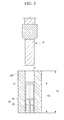
FIG. 3 is a cross-sectional view illustrating a state in which an inner cylinder, a sealing member, and a piston are disassembled in the pressure device shown inFIG. 2 . -
FIG. 4 is a partial cross-sectional view illustrating another embodiment of a second piston in the pressure device shown inFIG. 2 . -
FIG. 5 is a partial cross-sectional view illustrating a state in which a first flange and a first locking nut are separated from each other in the pressure device shown inFIG. 2 . -
FIG. 6 is a partial cross-sectional view illustrating a state in which a second flange and a second locking nut are separated from each other in the pressure device shown inFIG. 2 . -
FIG. 7 is a partial cross-sectional view illustrating a sealing member, a lead wire, and a protection tube in the pressure device shown inFIG. 2 . -
FIG. 8 is a partial cross-sectional view illustrating another embodiment of an inner cylinder and an outer cylinder in the pressure device shown inFIG. 2 . - When an element such as a layer, film, region, or substrate is referred to as being "on" another element, it can be directly on the other element or intervening elements may also be present. On the contrary, when an element such as a layer, film, region, or substrate is referred to as being "directly on", intervening elements are not present.
- Terms representing relative spaces such as "below", "on", etc. may be used for more easily describing a relationship between any one part and the other part that are shown in the figure. These terms are intended to include other meanings or operations of a used device altogether with meanings intended in the figure. For example, when the device of the figure is turned over, any elements described to be positioned "below" another element is described to be positioned "on" other elements. Accordingly, an exemplary term such as "below" includes all downward elements. The device can rotate at 90 degrees or another angle and a term representing a relative space is also analyzed thereby.
- Special terms used herein are just used for referring a specific embodiment, but are not intended to limit the present invention. Singular types used herein include plural types as long as words do not represent a meaning clearly contrary thereto. A meaning "include" used in the specification embodies a specific characteristic, region, , step, operation, element, and/or component and does not except existence or addition of another specific characteristic, region, step, operation, element, and/or group.
- Although differently not defined, all terms including technical terms and scientific terms used herein have the same meanings as meanings understood by those skilled in the art. Terms defined in dictionaries, which are used in general dictionaries are analyzed to have meanings that coincide with relevant technical documents and currently disclosed contents. As long as the terms not defined, the terms not analyzed as ideal meanings or official meanings.
- The exemplary embodiments of the present invention, which are described by referring to cross-sectional views shows preferred embodiments of the present invention in detail. As a result, various modifications of diagrams, for example, modifications of manufacturing methods and/or specifications are expected. Accordingly, the exemplary embodiments are not limited to a specific form of an illustrated region and include modifications of forms by manufacturing. Therefore, the regions shown in the figure are originally approximate, forms thereof are intended to illustrate accurate forms of the regions, but limit the scope of the present invention.
-
FIG. 1 is a perspective view of apressure device 100 for measuring a physical property according to an exemplary embodiment of the present invention.FIG. 2 is a cross-sectional view of apressure device 100 for measuring a physical property according to an exemplary embodiment of the present invention. The structure of thepressure device 100 shown inFIGS. 1 and2 just exemplifies the present invention, but the present invention is not limited thereto. Therefore, the structure of thepressure device 100 may be modified into other forms. - Referring to
FIGS. 1 and2 , thepressure device 100 for measuring a physical property includes a sealingmember 10, aninner cylinder 12, anouter cylinder 14, apiston 16, afirst locking nut 18, and asecond locking nut 20. - The sealing
member 10 incorporates asample 22 which is a measurement target material and apressure transmission medium 24 surrounding thesample 22. The sealingmember 10 includes a sealingcap 26 of which a lower end is opened and asupport 28 joined to the lower end of the sealingcap 26. The sealingcap 26 is directly applied with a pressure from thepiston 16. This pressure is transmitted to thesample 22 through thepressure transmission medium 24 and induces changes of electrical and magnetic states by changing the volume and a lattice structure of thesample 22. - The sealing
cap 26 may be fabricated by a polymer resin and thesupport 28 may be fabricated by a high-rigidity metal. For example, the sealingcap 26 may be fabricated by polytetrafluoroethylene (PTFE) having excellent thermal and chemical properties and thesupport 28 may be fabricated by a copper-beryllium (CuBe) alloy having excellent fatigue-resistant, wear-resistant, and corrosion-resistant properties. -
FIG. 3 is a cross-sectional view illustrating state in which theinner cylinder 12, the sealingmember 10, and thepiston 16 are disassembled in thepressure device 100 shown inFIG. 2 . - Referring to
FIG. 3 , theinner cylinder 12 is provided with a through-hole 121 in which the sealingmember 10 is installed. The through-hole 121 is configured to pass through theinner cylinder 12 in a vertical direction ofFIG. 3 . A height H1 of theinner cylinder 12 is higher than a height H2 of the sealingmember 10. The sealingmember 10 is positioned below the through-hole 121 of theinner cylinder 12. Therefore, a space into which thepiston 16 is inserted is provided above the sealingmember 10. - An outer diameter of the sealing
cap 26 may be formed a bit larger than a diameter of the through-hole 121. Accordingly, when the sealingcap 26 is pushed into the through-hole 121, the sealingcap 26 presses on the through-hole 121, such that the sealingcap 26 can be firmly fixed to the through-hole 121. At this time, as surface roughness of the sealingcap 26 increases, the sealingcap 26 may be torn by pressurization through thepiston 16. Therefore, the sealingcap 26 preferably has small surface roughness as possible. - In the pressurization through the
piston 16, friction may be generated between the sealingcap 26 and theinner cylinder 12. In order to reduce the friction, the through-hole 121 of theinner cylinder 12 may be polished or a high-pressure lubricant containing polytetrafluoroethylene (PTFE) powder may be applied between the sealingcap 26 and theinner cylinder 12. - Referring back to
FIG. 2 , theouter cylinder 14 surrounds theinner cylinder 12 in close contact with an outer surface of theinner cylinder 12. Mechanical rigidity and durability of thepressure device 100 can be enhanced by a dual structure of the inner andouter cylinders inner cylinder 12 from the through-hole 121 (seeFIG. 3 ) of theinner cylinder 12 in the pressurization. In this case, theouter cylinder 14 suppresses propagation of the crack of theinner cylinder 12 to thereby enhance the durability of thepressure device 100. - In addition, the
inner cylinder 12 and theouter cylinder 14 are detachably joined to each other. Accordingly, theinner cylinder 12 can be easily separated and replaced from theouter cylinder 14 in accordance with experimental conditions. - For example, a
first thread 301 may be formed at a portion of the outer surface of theinner cylinder 12 and a second thread 302 may be formed at a portion of an inner surface of theouter cylinder 14 corresponding thereto. The first andsecond threads 301 and 302 may be positioned on an upper part of the inner andouter cylinders inner cylinder 12 is firmly fixed to the inside of theouter cylinder 14 by screw engagement and may be easily separated from theouter cylinder 14 if needed. - The
outer cylinder 14 is fabricated by a non-magnetic high-rigidity metal.
For example, theouter cylinder 14 may be fabricated by a nickel-chrome-aluminum (NiCrAl) alloy. The nickel-chrome-aluminum alloy has high durability under low-temperature, high-pressure, and high-magnetic field conditions and has high adaptability to a magnetic field environment which rapidly changes. - In particular, since the nickel-chrome-aluminum alloy includes aluminum, the nickel-chrome-aluminum alloy has lower magnetic susceptibility than a compatibilized MP35N alloy (nickel-cobalt-chrome-molybdenum alloy) and shows more excellent performance under the high-magnetic field condition. In addition, the nickel-chrome-aluminum alloy has rigidity higher than maraging steel having high rigidity in spite of high magnetic susceptibility at a low temperature. The nickel-chrome-aluminum alloy used for the
outer cylinder 14 has Rockwell rigidity of 52. - Further, a reinforced nickel-chrome-aluminum alloy which is aged at 850°C can increase a maximum pressure which can be achieved by the piston up to 4 GPa at 4.2 K. The nickel-chrome-aluminum alloy has an electrical resistance of approximately 90 µΩcm at 300 K and an electrical resistance of approximately 50 µΩcm at 4.2 K. As a slight change of the electrical resistance caused by a temperature change, an electrical structure of the nickel-chrome-aluminum alloy is slightly changed by applying a high magnetic field. Accordingly, the
outer cylinder 14 fabricated by the nickel-chrome-aluminum alloy can maintain high durability even under the high-magnetic field environment. - The
inner cylinder 12 may be fabricated by the nickel-chrome-aluminum alloy similarly as theouter cylinder 14. Meanwhile, theinner cylinder 12 may be fabricated by a material different from the material of theouter cylinder 14 depending on experimental conditions such as temperature and pressure ranges, etc. For example, theinner cylinder 12 may be fabricated by any one among the copper-beryllium alloy, the maraging steel, and the nickel-cobalt-chrome-molybdenum alloy. - In the
outer cylinder 14, afirst flange 32 is formed at an end (upper end ofFIG. 2 ) of a portion to which the pressure is applied and asecond flange 34 is formed at an opposite end (lower end ofFIG. 2 ) to thefirst flange 32. Outer diameters of the first andsecond flanges outer cylinder 14. A predetermined space is formed inside of the first andsecond flanges - The
piston 16 may include afirst piston 36, apressure transmission pad 38, and asecond piston 40. Thefirst piston 36 is joined to the through-hole 121 (seeFIG. 3 ) of theinner cylinder 12 to pressurize the sealingcap 26. Thepressure transmission pad 38 is fixed to an upper end of thefirst piston 36 and thesecond piston 40 is fixed to an upper end of thepressure transmission pad 38. Thepressure transmission pad 38 may have a width larger than the first andsecond pistons - The first and
second pistons pressure transmission pad 38 may be fabricated by the non-magnetic high-rigidity metal, i.e., tungsten carbide. Thesecond piston 40 can be directly applied with the pressure from a hydraulic ram (not shown) in close contact with the hydraulic ram. Meanwhile, as shown inFIG. 4 , thesecond piston 40 is joined to apiston holder 42 to receive the pressure from the hydraulic ram through thepiston holder 42. - Referring to
FIG. 4 , thepiston holder 42 includes a back-up member 44 connected to an upper end of thesecond piston 40 and aholder body 46 that surrounds the entirety of the back-up member 44 and a portion of an upper part of thesecond piston 40. The back-up member 44 has a width larger than thesecond piston 40 and may be fabricated by the same material as thesecond piston 40. Theholder body 46 has a width larger than the back-up member 44 and may be fabricated by a different material from the materials of thesecond piston 40 and the back-up member 44. For example, theholder body 46 may be fabricated by stainless steel having high rigidity and corrosion resistance. - When the
second piston 40 is directly applied with the pressure from the hydraulic ram, thefirst piston 36 may be broken while scratching an inner wall of the inner cylinder 12 (seeFIG. 2 ) even though the first piston 36 (seeFIG. 2 ) and thesecond pistons 40 are deviated from theinner cylinder 12. However, when thepiston holder 42 is used, thesecond piston 40 can be stably applied with the pressure, such that it is possible to prevent thefirst piston 36 from being broken. - Referring to
FIG. 2 , thefirst locking nut 18 is detachably joined to the inside of thefirst flange 32. For this, athird thread 481 may be formed on an inner wall of thefirst flange 32 and afourth thread 482 may be formed on an outer wall of thefirst locking nut 18. Thefirst locking nut 18 serves to maintain the pressure with thepiston 16 by fixing a position of thepiston 16 pressurized by the hydraulic ram even after the hydraulic ram is separated from thepiston 16. -
FIG. 5 is a partial cross-sectional view illustrating a state in which thefirst flange 32 and thefirst locking nut 18 are separated from each other in thepressure device 100 shown inFIG. 2 . - Referring to
FIG. 5 , an opening for passing thepiston 16 is formed in thefirst locking nut 18. The opening includes afirst opening 181 corresponding to thepressure transmission pad 38 and asecond opening 182 corresponding to thesecond piston 40. After thepiston 16 is applied with the pressure from the hydraulic ram, thefirst locking nut 18 is fastened until an upper end of thefirst opening 181 reaches thepressure transmission pad 38, thereby fixing the position of thepiston 16. - Referring back to
FIG. 2 , thesecond locking nut 20 is detachably joined to the inside of thesecond flange 34. For this, afifth thread 501 may be formed on an inner wall of thesecond flange 34 and asixth thread 502 may be formed on an outer wall of thesecond locking nut 20. Thesecond locking nut 20 serves to fix positions of thesupport 28 and a fixingmember 52 by pressing the fixingmember 52 connected to thesupport 28. -
FIG. 6 is a partial cross-sectional view illustrating a state in which thesecond flange 34 and thesecond locking nut 20 are separated from each other in thepressure device 100 shown inFIG. 2 . - Referring to
FIG. 6 , the fixingmember 52 is fixed to a lower end of thesupport 28 and has a width larger than thesupport 28. Accordingly, when thesupport 28 is pushed into the through-hole 121 of theinner cylinder 12, the fixingmember 52 is in close contact with the lower end of theinner cylinder 12. The fixingmember 52 may be fabricated by tungsten carbide. Athird opening 201 corresponding to the fixingmember 52 is formed in thesecond locking nut 20. Thesecond locking nut 20 is fastened until a lower end of thethird opening 201 reaches the fixingmember 52, thereby pressurizing thesupport 28 and the fixingmember 52. - Referring back to
FIG. 2 , thefirst locking nut 18 and thesecond locking nut 20 may be fabricated by the same material as theouter cylinder 14 so as to have the same mechanical and thermal properties as theouter cylinder 14. That is, the first andsecond locking nuts - The
pressure device 100 includes alead wire 54 that passes through thesupport 28, the fixingmember 52, and thesecond locking nut 20, and aprotection tube 56 that surrounds thelead wire 54. One end of thelead wire 54 is fixed to thesample 22 in the sealingcap 26 and the other end of thelead wire 54 is connected with a measurement device (not shown) to thereby electrically connect the measurement device with thesample 22. -
FIG. 7 is a partial cross-sectional view illustrating the sealingmember 10, thelead wire 54, and theprotection tube 56 in thepressure device 100 shown inFIG. 2 . - Referring to
FIG. 7 , theprotection tube 56 passes through thesupport 28 in close contact with thesupport 28. Thelead wire 54 is positioned inside of theprotection tube 56 with being surrounded by an insulatingadhesive 58. Thelead wire 54 may be a copper wire and may be mounted with being twisted in order to reduce an electromagnetic pickup. - The
protection tube 56 may be fabricated by the polymer resin or a metal such as cupro-nickel or stainless steel. Theprotection tube 56 prevents a short-circuit between thelead wire 54 and thesupport 28 at a high pressure of 4.0 GPa and a low temperature of 4K and can effectively secure stability of thelead wire 54. However, when theprotection tube 56 is fabricated by the metal, theprotection tube 56 has conductivity, such that thelead wire 54 and theprotection tube 56 must not be in contact with each other. - The insulating
adhesive 58 may be an epoxy-based adhesive. After the insulatingadhesive 58 is inserted into theprotection tube 56 altogether with thelead wire 54, the insulatingadhesive 58 is slowly cured and fixed to theprotection tube 56. At this time, when bubbles rise in the insulatingadhesive 58, the bubbles becomes increasingly larger at the time of applying a high pressure to thepressure device 100 or lowering a temperature, such that the insulatingadhesive 58 may be broken. Accordingly, the insulatingadhesive 58 may be degassed in a desiccator (not shown) for approximately 60 minutes. - Referring back to
FIG. 2 , a hollow having a diameter larger than a diameter of theprotection tube 56 is formed in the fixingmember 52 and thesecond locking nut 20 and surrounds theprotection tube 56. In addition, acylinder holder 60 supporting thepressure device 100 may be joined to an outer wall of thesecond flange 34. - The
pressure device 100 having the above-mentioned configuration pressurizes the sealingcap 26 with thepiston 16 to induce a change of the volume and a change of an electrical state of thesample 22 inside of the sealingcap 26. Therefore, the measurement device (not shown) may measure the change of the electrical state of thesample 22 through thelead wire 54 fixed to thesample 22 and an experimenter can investigate the electrical and magnetic properties through a measurement result. - The
pressure device 100 according to the exemplary embodiment has a dual structure of the inner andouter cylinders inner cylinder 12 is separated from theouter cylinder 14 in accordance with the experimental conditions, such that theinner cylinder 12 can be easily replaced with aninner cylinder 12 of a different material. Further, the sealingmember 10 is separated from theinner cylinder 12 and the sealingcap 26 is separated from thesupport 28 to thereby easily replace thesample 22. - Further, in the
pressure device 100 according to the exemplary embodiment, the inner andouter cylinders second locking nuts pressure device 100 can effectively endure repetitive thermal cycling and perform accurate measurement under a cryogenic high-pressure and high-magnetic field environment. - Meanwhile, in
FIG. 2 , although the outer surface of theinner cylinder 12 and the inner surface of theouter cylinder 14 are formed to be vertical, an outer surface of an inner cylinder 12' and an inner surface of an outer cylinder 14' may be formed to be slant as shown inFIG. 8 . - Referring to
FIG. 8 , the outer surface of the inner cylinder 12' has a diameter that gradually decreases from a pressure applied side to a side opposite to the pressure applied side. InFIG. 8 , the pressure applied side is an upper side and the opposite side is a lower side. Accordingly, in the inner cylinder 12', a diameter (D1 ofFIG. 8 ) of the pressure applied side is larger than a diameter (D2 ofFIG. 8 ) of the opposite side. The inner surface of the outer cylinder 14' has the same shape as the outer surface of the inner cylinder 12'. - By the structure shown in
FIG. 8 , when the pressure is applied by thepiston 16, a wedge effect is induced, such that it is possible to effectively prevent the inner cylinder 12' from being deviated outside of the outer cylinder 14'. - While this invention has been described in connection with what is presently considered to be practical exemplary embodiments, it is to be understood that the invention is not limited to the disclosed embodiments, but, on the contrary, is intended to cover various modifications and equivalent arrangements included within the spirit and scope of the appended claims.
- While this invention has been described in connection with what is presently considered to be practical exemplary embodiments, it is to be understood that the invention is not limited to the disclosed embodiments, but, on the contrary, is intended to cover various modifications and equivalent arrangements included within the spirit and scope of the appended claims.
Claims (16)
- A pressure device for measuring a physical property, comprising:a sealing member adapted to incorporate a sample and a pressure transmission medium that surrounds the sample;an inner cylinder that is provided with a through-hole in which the sealing member is installed;an outer cylinder that surrounds the inner cylinder in close contact with an outer surface of the inner cylinder; anda piston joined to the through-hole of the inner cylinder to pressurize the sealing member,
wherein the inner cylinder and the outer cylinder are fabricated by a non-magnetic metal, and
the volume and a lattice structure of the sample are changed by pressurizing the sample with the piston to thereby induce a change of electrical and magnetic properties of the sample. - The pressue device of claim 1, wherein:at least one of the inner cylinder and the outer cylinder is fabricated by the nickel-chrome-aluminum alloy.
- The pressure device of claim 1, wherein:the outer cylinder is fabricated by a nickel-chrome-aluminum alloy and the inner cylinder is fabricated by any one of a copper-beryllium alloy, maraging steel, and a nickel-cobalt-chrome-molybdenum alloy.
- The pressure device of claim 1, wherein:the sealing member includes,a sealing cap that is fabricated by polytetraflouoroethylene (PTFE), is in closed contact with the piston and of which an end opposite to the piston is opened; anda support that is fabricated by the copper-beryllium alloy, and is joined to the end of the sealing cap.
- The pressure device of claim 4, wherein:an outer diameter of the sealing cap is larger than a diameter of the through-hole, such that the sealing cap presses on the through-hole.
- The pressure device of claim 4, wherein:a lubricant containing polytetrafluoroethylene (PTFE) powder is applied between the sealing cap and the inner cylinder.
- The pressure device of claim 1, wherein:the inner cylinder is detachably joined to the outer cylinder,wherein a thread is formed on an outer surface of the inner cylinder and an inner surface of the outer cylinder, such that the inner cylinder and the outer cylinder are joined to each other by screw engagement.
- The pressure device of claim 1, wherein:the outer cylinder has a first flange formed at a pressure applied end thereof and a second flange formed at the other end opposite to the first flange, andthe pressure device for measuring a physical property further includes,a first locking nut that screw-engages with the inside of the first flange to fix a position of the piston; anda second locking nut that screw-engages with the inside of the second flange to fix a position of the sealing member.
- The pressure device of claim 8, wherein:the piston includes,a first piston joined to the inner cylinder;a pressure transmission pad connected to the first piston in a pressure applied direction; anda second piston connected to the pressure transmission pad in the pressure applied direction,wherein the pressure transmission pad has a width larger than the first and second pistons,
wherein at least one of the first piston, the pressure transmission pad, and the second piston are fabricated by tungsten carbide. - The pressure device of claim 9, further comprising:a piston holder that surrounds a pressure applied end of the second piston,
wherein the piston holder includes,a back-up member fixed to the end of the second piston; anda holder body that surrounds the entirety of the back-up member and a portion of the second piston. - The pressure device of claim 10, wherein:the back-up member has a width larger than the second piston and at least one of the second piston and the back-up member is fabricated by tungsten carbide.
- The pressure device of claim 10, wherein:the holder body has a width larger than the back-up member, at least one of the second piston and the back-up member is fabricated by tungsten carbide, and the holder body is fabricated by stainless steel.
- The pressure device of claim 9, wherein:the first locking nut has a first opening having a shape corresponding to a shape of the pressure transmission pad and a second opening having a shape corresponding to a shape of the second piston.
- The pressure device of claim 8, further comprising:a fixing member that is fixed to the sealing member and is in closed contact with the end of the inner cylinder in the inside of the second flange,wherein the second locking nut has an opening having a shape corresponding to the fixing member.
- The pressure device of claim 8, wherein:at least one of the outer cylinder, the first locking nut, and the second locking nut is fabricated by the nickel-chrome-aluminum alloy.
- The pressure device of claim 14, further comprising:a lead wire that passes through the sealing member, the fixing member, and the second locking nut, and is electrically connected to the sample; anda protection tube that surrounds the lead wire with an insulating adhesive interposed therebetween,wherein the lead wire is a copper wire and is mounted on the protection tube with being twisted, and the insulating adhesive is an epoxy-based adhesive and the protection tube is fabricated by any one of a polymer resin, cupro-nickel, and stainless steel.
Applications Claiming Priority (1)
| Application Number | Priority Date | Filing Date | Title |
|---|---|---|---|
| KR1020090007707A KR101014820B1 (en) | 2009-01-30 | 2009-01-30 | Pressure device for measuring physical quantity |
Publications (2)
| Publication Number | Publication Date |
|---|---|
| EP2214006A2 true EP2214006A2 (en) | 2010-08-04 |
| EP2214006A3 EP2214006A3 (en) | 2014-03-05 |
Family
ID=42110184
Family Applications (1)
| Application Number | Title | Priority Date | Filing Date |
|---|---|---|---|
| EP09172173.8A Withdrawn EP2214006A3 (en) | 2009-01-30 | 2009-10-05 | Pressure device for measuring physical property |
Country Status (2)
| Country | Link |
|---|---|
| EP (1) | EP2214006A3 (en) |
| KR (1) | KR101014820B1 (en) |
Cited By (6)
| Publication number | Priority date | Publication date | Assignee | Title |
|---|---|---|---|---|
| CN106872082A (en) * | 2017-04-28 | 2017-06-20 | 中国地震局地壳应力研究所 | A kind of body strain dynamic characteristic measuring instrument and measuring method |
| CN107715798A (en) * | 2017-10-20 | 2018-02-23 | 金华职业技术学院 | The device of gas polymerisation is carried out under the conditions of a kind of cryogenic high pressure |
| CN107817146A (en) * | 2017-11-06 | 2018-03-20 | 华侨大学 | Dual compression preparation of soil sample device and method for making sample |
| CN115876571A (en) * | 2022-12-28 | 2023-03-31 | 北京城建勘测设计研究院有限责任公司 | Rock hardness detection device for geological exploration |
| CN117629767A (en) * | 2024-01-18 | 2024-03-01 | 南京迈豪幕墙工程有限公司 | A building curtain wall safety performance detection system |
| CN117732370A (en) * | 2024-01-24 | 2024-03-22 | 杭州师范大学 | Single-shaft pressurizing device and physical property parameter measuring system |
Families Citing this family (1)
| Publication number | Priority date | Publication date | Assignee | Title |
|---|---|---|---|---|
| US20260168866A1 (en) * | 2023-04-07 | 2026-06-18 | Ewha University - Industry Collaboration Foundation | Thermometer enclosure, obturator, obturator-thermometer enclosure assembly, and pressure cell |
Family Cites Families (2)
| Publication number | Priority date | Publication date | Assignee | Title |
|---|---|---|---|---|
| GB2346669B (en) * | 1999-02-15 | 2002-12-18 | Ian Ross Walker | Pressure cell |
| GB2438838A (en) * | 2006-06-08 | 2007-12-12 | Patricia Lebre Alireza | Miniature High Pressure Cell for Sample Characterization. |
-
2009
- 2009-01-30 KR KR1020090007707A patent/KR101014820B1/en active Active
- 2009-10-05 EP EP09172173.8A patent/EP2214006A3/en not_active Withdrawn
Cited By (8)
| Publication number | Priority date | Publication date | Assignee | Title |
|---|---|---|---|---|
| CN106872082A (en) * | 2017-04-28 | 2017-06-20 | 中国地震局地壳应力研究所 | A kind of body strain dynamic characteristic measuring instrument and measuring method |
| CN107715798A (en) * | 2017-10-20 | 2018-02-23 | 金华职业技术学院 | The device of gas polymerisation is carried out under the conditions of a kind of cryogenic high pressure |
| CN107817146A (en) * | 2017-11-06 | 2018-03-20 | 华侨大学 | Dual compression preparation of soil sample device and method for making sample |
| CN107817146B (en) * | 2017-11-06 | 2023-08-29 | 华侨大学 | Double compression soil sample preparation device and sample preparation method |
| CN115876571A (en) * | 2022-12-28 | 2023-03-31 | 北京城建勘测设计研究院有限责任公司 | Rock hardness detection device for geological exploration |
| CN117629767A (en) * | 2024-01-18 | 2024-03-01 | 南京迈豪幕墙工程有限公司 | A building curtain wall safety performance detection system |
| CN117629767B (en) * | 2024-01-18 | 2024-04-12 | 南京迈豪幕墙工程有限公司 | A building curtain wall safety performance detection system |
| CN117732370A (en) * | 2024-01-24 | 2024-03-22 | 杭州师范大学 | Single-shaft pressurizing device and physical property parameter measuring system |
Also Published As
| Publication number | Publication date |
|---|---|
| KR20100088462A (en) | 2010-08-09 |
| KR101014820B1 (en) | 2011-02-14 |
| EP2214006A3 (en) | 2014-03-05 |
Similar Documents
| Publication | Publication Date | Title |
|---|---|---|
| Zhao et al. | Effects of surface roughness, temperature and pressure on interface thermal resistance of thermal interface materials | |
| KR101014820B1 (en) | Pressure device for measuring physical quantity | |
| Kobayashi et al. | Nonmagnetic indenter-type high-pressure cell for magnetic measurements | |
| US8808010B2 (en) | Insulated metal socket | |
| Schmiedeshoff et al. | Versatile and compact capacitive dilatometer | |
| Ralphs et al. | Thermal conductivity enhancement of soft polymer composites through magnetically induced percolation and particle–particle contact engineering | |
| Lian et al. | Friction and wear characteristics of magneto-rheological elastomers based on silicone/polyurethane hybrid | |
| Hara et al. | Very wide sensing range and hysteresis behaviors of tactile sensor developed by embedding soft ionic gels in soft silicone elastomers | |
| KR20210089444A (en) | Test socket | |
| Wang et al. | Stimuli dependent impedance of conductive magnetorheological elastomers | |
| Stewart et al. | Biaxial inflation stretch test for flexible electronics | |
| Nishio et al. | Piezoresistive effect of plain-weave CFRP fabric subjected to cyclic loading | |
| JP2009540283A (en) | Small high pressure cell for sample characterization | |
| Webb et al. | A multi-component nanocomposite screen-printed ink with non-linear touch sensitive electrical conductivity | |
| Chen et al. | Biphasic liquid metal composite for strain sensor with high stretchability and sensitivity | |
| Xu et al. | Design and simulation of a 7.0 T conduction cooled superconducting magnet | |
| US12002613B2 (en) | Double-sided cooling package of inductor | |
| Tateiwa et al. | Note: Improved sensitivity of magnetic measurements under high pressure in miniature ceramic anvil cell for a commercial SQUID magnetometer | |
| CN102317660B (en) | Piston cylinder-type high-pressure generating device | |
| Fist et al. | In situ three point bending device for measurements of vibrational response of ceramics under stress by microRaman spectroscopy | |
| Rüetschi et al. | Adaptation of the Bridgman anvil cell to liquid pressure mediums | |
| Kwon et al. | In Twisting Motion, Stress‐Free Zone of Wearable Electronics | |
| CN112606946B (en) | High-pressure-resistant watertight optical window structure capable of compensating compression bending of support shell | |
| Wang et al. | Electromechanical coupling measurement of a new giant magnetostrictive structure for double-nut ball screw pre-tightening | |
| Seeber et al. | Toward a standard for critical current versus axial strain measurements of Nb3Sn |
Legal Events
| Date | Code | Title | Description |
|---|---|---|---|
| PUAI | Public reference made under article 153(3) epc to a published international application that has entered the european phase |
Free format text: ORIGINAL CODE: 0009012 |
|
| 17P | Request for examination filed |
Effective date: 20091005 |
|
| AK | Designated contracting states |
Kind code of ref document: A2 Designated state(s): AT BE BG CH CY CZ DE DK EE ES FI FR GB GR HR HU IE IS IT LI LT LU LV MC MK MT NL NO PL PT RO SE SI SK SM TR |
|
| AX | Request for extension of the european patent |
Extension state: AL BA RS |
|
| PUAL | Search report despatched |
Free format text: ORIGINAL CODE: 0009013 |
|
| AK | Designated contracting states |
Kind code of ref document: A3 Designated state(s): AT BE BG CH CY CZ DE DK EE ES FI FR GB GR HR HU IE IS IT LI LT LU LV MC MK MT NL NO PL PT RO SE SI SK SM TR |
|
| AX | Request for extension of the european patent |
Extension state: AL BA RS |
|
| RIC1 | Information provided on ipc code assigned before grant |
Ipc: G01N 27/02 20060101AFI20140124BHEP Ipc: G01N 1/28 20060101ALI20140124BHEP Ipc: G01N 27/72 20060101ALI20140124BHEP |
|
| STAA | Information on the status of an ep patent application or granted ep patent |
Free format text: STATUS: THE APPLICATION IS DEEMED TO BE WITHDRAWN |
|
| 18D | Application deemed to be withdrawn |
Effective date: 20140906 |