EP2213984A2 - Method and work machine - Google Patents
Method and work machine Download PDFInfo
- Publication number
- EP2213984A2 EP2213984A2 EP10152249A EP10152249A EP2213984A2 EP 2213984 A2 EP2213984 A2 EP 2213984A2 EP 10152249 A EP10152249 A EP 10152249A EP 10152249 A EP10152249 A EP 10152249A EP 2213984 A2 EP2213984 A2 EP 2213984A2
- Authority
- EP
- European Patent Office
- Prior art keywords
- sensor
- environmental attribute
- signal
- accelerated output
- representative
- Prior art date
- Legal status (The legal status is an assumption and is not a legal conclusion. Google has not performed a legal analysis and makes no representation as to the accuracy of the status listed.)
- Granted
Links
Images



Classifications
-
- G—PHYSICS
- G01—MEASURING; TESTING
- G01D—MEASURING NOT SPECIALLY ADAPTED FOR A SPECIFIC VARIABLE; ARRANGEMENTS FOR MEASURING TWO OR MORE VARIABLES NOT COVERED IN A SINGLE OTHER SUBCLASS; TARIFF METERING APPARATUS; MEASURING OR TESTING NOT OTHERWISE PROVIDED FOR
- G01D3/00—Indicating or recording apparatus with provision for the special purposes referred to in the subgroups
- G01D3/02—Indicating or recording apparatus with provision for the special purposes referred to in the subgroups with provision for altering or correcting the law of variation
Definitions
- the present invention relates to a sensor response time acceleration method and apparatus, and more particularly to a sensor response time acceleration method and apparatus applied to a work machine.
- the internal combustion engine utilizes a variety of sensors that provide information to a controller that is used to control the operating attributes of the engine. Information from the sensors should ideally reflect the condition that the sensor is measuring. In order for this to be the case the sensor needs to respond immediately to the changes so that the environmental attribute being sensed by the sensor is reported to the controller immediately.
- sensors do take a period of time to adapt to the environmental change so there is an inherent slow response in the information being supplied to controller when operating conditions of the internal combustion engine change.
- Sensors such as temperature sensors, oxygen (O 2 ) sensors and nitrous oxide (NO X ) sensors and the like have a notable slow response as compared to the response of a control system that changes the engine's operating parameters.
- the slow response is an inherent trait in these sensors, for example, if a temperature sensor is moved from ice water to boiling water the sensor output will not immediately change to reflect the current environment but will change over time.
- the change in the output can be expressed as a function of a differential equation that describes the heat transfer process of conduction of heat to or from the temperature sensor.
- a problem with the slow response time of sensors is that control algorithms function based upon the reading of the sensor, which may be a reading of a historical attribute, and not the current attribute being encountered by the sensor. It is desirable to improve the speed at which information from sensors is available so that the changes in the conditions to which they are exposed can be responded to in a timelier manner and to provide a more accurate picture of the measured attribute to the controller. Such a device would provide a greater ability to control the functions of the internal combustion engine, particularly those that need fast responses.
- Some techniques that attempt to improve the response time of sensors use a system looking at the change of temperature over a unit of time to predict the temperature.
- the disadvantage of these prior art methods is that they amplify the noise of the temperature sensor signal resulting in inaccurate assumptions about the environmental attribute.
- What is needed in the art is a way to accelerate the response of sensors without introducing unwanted noise so that the environment in which the sensor is operating can rapidly be assessed so that an engine control can quickly respond to the changes to the environmental attribute.
- the present invention provides a sensor response time acceleration method including the steps of reading a signal step and an operating on the signal step.
- the reading a signal step may include reading a signal from a sensor, the signal representative of an environmental attribute as detected by the sensor.
- the operation on the signal step may include operating on the signal with a function of an inverse model of the sensor and a function representative of a desired sensor model to yield an accelerated output representative of the environmental attribute.
- the present invention consists of a work machine including a structural component, at least one sensor and a controller.
- the sensor may output a signal representative of an environmental attribute sensed by the at least one sensor.
- the at least one sensor may be coupled to the structural component.
- the controller may be configured to receive the signal and arrive at a value for the environmental attribute by executing the steps of a method.
- the method may includes the step of operating on the signal with a function of an inverse model of the sensor and a function representative of a desired sensor model to yield an accelerated output representative of the environmental attribute.
- a work machine 10 which may be an agricultural machine, a construction machine, a forester machine or a vehicle.
- Machine 10 includes an engine 12, a controller 14 and a display 16. Controller 14 is a communication with display 16 as well as with control actuators associated with engine 12.
- Engine 12 also includes a flow path structural component 18 through which a mass flow 20 traverses. Sensors 22 and 24 are mounted to structural component 18 and are situated to measure environmental attributes of mass flow 20 passing thereby.
- sensor 22 will be referred to as a flow sensor 22 and sensor 24 will be referred to as a temperature sensor 24.
- Flow sensor 22 and temperature sensor 24 are as their name infers testing specific environmental attributes of mass flow 20.
- Mass flow 20 may be an airflow that can represent combusted gas flowing through flow path structural component 18 or some other mass flow such as coolant within engine 12.
- Controller 14 is in communication with sensors 22 and 24 and receives signals therefrom. For purposes of description of the present invention it will be illustrated as controller 14 carrying out elements of the present invention, although it is understood that an apparatus separate for controller 14 can perform this function and feed a signal to conroller14 the functions of the present invention can even be imbedded into sensor 22 and/or 24 as yet another alternative. It is also understood that temperature sensor 24 could have been some other sensor such as an oxygen sensor or a nitrous oxide sensor. As mass flow 20 flows past sensors 22 and 24 changes in environmental attributes of mass flow 20 are detected by sensors 22 and 24, such as the velocity of mass flow 20 is detected by sensor 22 and the temperature of mass flow 20 is detected by sensor 24.
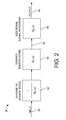
- a method 50 including an inverse model 52 of sensor 24, a desired model 54 of sensor 24 and additional signal processing 56.
- This example of the inventive method is one implementation using first order equations and it is also contemplated to carry out the invention with transfer functions of a higher order.
- Figs. 2 and 3 illustrate one example of the inventive method
- G m z z ⁇ 1 - m / z - m
- G n z z ⁇ 1 - n / z - n
- G p z z ⁇ 1 - p / z - p ⁇ optional signal processing
- a function of the present invention is to accelerate the response time of the sensors being utilized.
- the "m” represents the measurement dynamics of the assumed first order system.
- the "n” represents the desired or accelerated response dynamic in the discrete or "z” domain representation.
- the 'p' represents first order additional signal processing 56 that may be used to attenuate noise.
- An input signal 58 from sensor 24 is operated upon by the function of inverse model 52, the output of which is operated on by desired model 54 resulting in an output 60, which is the accelerated output signal 60.
- Signal 60 can be further operated on by additional signal processing 56 to provide a filtered output value 62.
- Additional signal processing 56 is an optional signal processing step, with there not being a requirement to further operate on accelerated output 60.
- Fig. 2 is provided to provide clarity in the explanation of the present invention, while a preferred implementation is presented in Fig. 3 .
- Accelerated Output f ⁇ previous Accelerated Output + g ⁇ Input + h ⁇ previous Input
- the 'm' can be thought of as representing the discrete time representation of the time constant of the first order filter representation of the measurement systems dynamic.
- the 'n' represents the discrete time representation of the time constant of the first order filter representation of the desired (accelerated) system dynamic
- the 'p' represents the discrete time representation of the time constant of the first order filter representation of the noise filter.
- the present invention is intended to be used to accelerate the response of slow measurement sensors; however, it can also be used to slow down the response of a fast measurement system.
- the values 'm', "n' or 'p' might be functions of the system operating conditions, such as the velocity of mass flow 20, and can be incorporated in controller 14 in the form of look-up tables or equations.
- Method 150 which can be thought of as an algorithm 150 includes an inverse model 152 of sensor 24, a desired model 154 of sensor 24 and a noise filter 156.
- the implementation of the elements of method 150 may be carried out by hardware, software or a combination thereof.
- An input signal 158 from sensor 24 is operated upon by the function of inverse model 152, and is also operated on by desired model 154 resulting in an output 160, which is the accelerated output signal 160.
- Signal 160 can be further operated on by noise filter 156 to provide a filtered accelerated output value 162.
- Noise filter 156 is an optional signal processing step, with there not being a requirement to further operate on accelerated output 160.
- a temperature sensor is moved from an ice water bath to boiling water and the response of the sensor output is illustrated as the solid line of Fig. 5 .
- the output of the signal processed by the present invention described above is illustrated as the dashed line.
- the sensor output may take approximately 40 seconds to substantially proximate a temperature that has very quickly changed from 0° C to 100° C.
- the accelerated sensor output anticipates the temperature and provides an output that it much more responsive since it is accelerated based upon the technique and apparatus of the present invention.
- the method of the present invention estimates the actual temperature based upon a rate of sensor value change and knowledge about how the senor behaves for a given change in the sensor value.
- the present invention is a signal processing method that takes the derivative of the change in measured temperature and is filtered to thereby get a faster sensor reading that is physically possible with sensor 24.
- the time domain of the sensor is needed and may be provided by the sensor supplier. For example, if the time constant is 10 seconds (variable A), and if we want a 2 second desired time constant (variable B), and a significantly faster noise filter such as 0.2 second time constant (variable C). Also it is noted that the time constant can vary by the velocity of mass flow 20 since the heat transfer varies by the flow of the mass passing the sensor, which can be data provided by a sensor manufacturer or determined in the application. Tables or equations can be utilized for the A values as a function of gas velocities and that B and C can also be a function of the gas velocity. As a result controller 14 will receive input from flow sensor 22 so that the variables A, B and C can be dynamically selected for the processing of the signal from sensor 24.
- the present invention advantageously receives the sensor output, which may be sampled in a time domain basis.
- the signal is processed by a function of an inverse model representation of the actual responsiveness of the sensor and by the desired responsiveness of the sensor with that accelerated output then being filtered to reduce any noise that may be generated by the real time system to provide an accelerated sensor output that controller 14 can then utilize for controlling engine 12.
- Another advantage of the present invention is that the elements may be carried out by software embedded into controller 14 with no additional hardware being needed.
- another advantage of the present invention is that the elements may be carried out in a separate apparatus so that a legacy controller can be used allowing a faster response of information thereto to improve the performance of a legacy work machine 10.
Landscapes
- Engineering & Computer Science (AREA)
- Technology Law (AREA)
- Physics & Mathematics (AREA)
- General Physics & Mathematics (AREA)
- Combined Controls Of Internal Combustion Engines (AREA)
- Testing Or Calibration Of Command Recording Devices (AREA)
Abstract
Description
- The present invention relates to a sensor response time acceleration method and apparatus, and more particularly to a sensor response time acceleration method and apparatus applied to a work machine.
- Work machines, such as agricultural and construction equipment utilize internal combustion engines. The internal combustion engine utilizes a variety of sensors that provide information to a controller that is used to control the operating attributes of the engine. Information from the sensors should ideally reflect the condition that the sensor is measuring. In order for this to be the case the sensor needs to respond immediately to the changes so that the environmental attribute being sensed by the sensor is reported to the controller immediately. However, in reality sensors do take a period of time to adapt to the environmental change so there is an inherent slow response in the information being supplied to controller when operating conditions of the internal combustion engine change.
- Sensors, such as temperature sensors, oxygen (O2) sensors and nitrous oxide (NOX) sensors and the like have a notable slow response as compared to the response of a control system that changes the engine's operating parameters. The slow response is an inherent trait in these sensors, for example, if a temperature sensor is moved from ice water to boiling water the sensor output will not immediately change to reflect the current environment but will change over time. The change in the output can be expressed as a function of a differential equation that describes the heat transfer process of conduction of heat to or from the temperature sensor.
- A problem with the slow response time of sensors is that control algorithms function based upon the reading of the sensor, which may be a reading of a historical attribute, and not the current attribute being encountered by the sensor. It is desirable to improve the speed at which information from sensors is available so that the changes in the conditions to which they are exposed can be responded to in a timelier manner and to provide a more accurate picture of the measured attribute to the controller. Such a device would provide a greater ability to control the functions of the internal combustion engine, particularly those that need fast responses.
- Some techniques that attempt to improve the response time of sensors use a system looking at the change of temperature over a unit of time to predict the temperature. The disadvantage of these prior art methods is that they amplify the noise of the temperature sensor signal resulting in inaccurate assumptions about the environmental attribute.
- What is needed in the art is a way to accelerate the response of sensors without introducing unwanted noise so that the environment in which the sensor is operating can rapidly be assessed so that an engine control can quickly respond to the changes to the environmental attribute.
- This object is achieved with the subject matter of the independent claims. The dependent claims recite advantageous features of embodiments of the invention.
- The present invention provides a sensor response time acceleration method including the steps of reading a signal step and an operating on the signal step. The reading a signal step may include reading a signal from a sensor, the signal representative of an environmental attribute as detected by the sensor. The operation on the signal step may include operating on the signal with a function of an inverse model of the sensor and a function representative of a desired sensor model to yield an accelerated output representative of the environmental attribute.
- In another embodiment the present invention consists of a work machine including a structural component, at least one sensor and a controller. The sensor may output a signal representative of an environmental attribute sensed by the at least one sensor. The at least one sensor may be coupled to the structural component. The controller may be configured to receive the signal and arrive at a value for the environmental attribute by executing the steps of a method. The method may includes the step of operating on the signal with a function of an inverse model of the sensor and a function representative of a desired sensor model to yield an accelerated output representative of the environmental attribute.
- The above-mentioned and other features and advantages of this invention, and the manner of attaining them, will become more apparent and the invention will be better understood by reference to the following description of an embodiment of the invention taken in conjunction with the accompanying drawings, wherein:
-
Fig. 1 is schematic illustration of a work machine using an embodiment of an apparatus and method of the present invention; -
Fig. 2 is a schematic block diagram illustrating an embodiment of a method of the present invention utilized in the work machine ofFig. 1 ; -
Fig. 3 is a schematic block diagram further illustrating the method ofFig. 2 ; -
Fig. 4 is a schematic block diagram illustrating a specific implementation of the method ofFigs. 2 or3 ; and -
Fig. 5 illustrates the acceleration of the response time of the sensors ofFig. 1 utilizing a method ofFigs. 2 ,3 or4 . - Corresponding reference characters indicate corresponding parts throughout the several views. The exemplification set out herein illustrates one embodiment of the invention, in one form, and such exemplification is not to be construed as limiting the scope of the invention in any manner.
- Referring now to the drawings, and more particularly to
Fig. 1 , there is illustrated awork machine 10, which may be an agricultural machine, a construction machine, a forester machine or a vehicle.Machine 10 includes anengine 12, acontroller 14 and adisplay 16.Controller 14 is a communication withdisplay 16 as well as with control actuators associated withengine 12.Engine 12 also includes a flow pathstructural component 18 through which amass flow 20 traverses.Sensors structural component 18 and are situated to measure environmental attributes ofmass flow 20 passing thereby. For ease ofdiscussion sensor 22 will be referred to as aflow sensor 22 andsensor 24 will be referred to as atemperature sensor 24.Flow sensor 22 andtemperature sensor 24 are as their name infers testing specific environmental attributes ofmass flow 20.Mass flow 20 may be an airflow that can represent combusted gas flowing through flow pathstructural component 18 or some other mass flow such as coolant withinengine 12. -
Controller 14 is in communication withsensors controller 14 carrying out elements of the present invention, although it is understood that an apparatus separate forcontroller 14 can perform this function and feed a signal to conroller14 the functions of the present invention can even be imbedded intosensor 22 and/or 24 as yet another alternative. It is also understood thattemperature sensor 24 could have been some other sensor such as an oxygen sensor or a nitrous oxide sensor. Asmass flow 20 flows pastsensors mass flow 20 are detected bysensors mass flow 20 is detected bysensor 22 and the temperature ofmass flow 20 is detected bysensor 24. - Now, additionally referring to
Figs. 2 and3 there is illustrated amethod 50 including aninverse model 52 ofsensor 24, a desiredmodel 54 ofsensor 24 andadditional signal processing 56. This example of the inventive method is one implementation using first order equations and it is also contemplated to carry out the invention with transfer functions of a higher order.Figs. 2 and3 illustrate one example of the inventive method, - Where:
- Gm( ) = Model of the actual sensor response. This can be provided by the sensor manufacturer, or derived from the information specified by the sensor manufacture, such as the time constant of the sensor.
- Gn( ) = Desired behavior of the sensor. This is the desired sensor response model, which can represent faster dynamic characteristics as compared to Gm( ).
- Gp(s) = Additional signal processing. Such as Low pass filtering for noise attenuation, notch filtering, band-pass filtering. This is optional and is determined by the needs of the system.
- In the s (continuous time) domain:



- where
b>a and c»a for a response time acceleration. - In the z (discrete time) domain:


- where
n<m and p<<m for a response time acceleration. - The implementation of the elements of
method 50 may be carried out by hardware, software or a combination thereof. A function of the present invention is to accelerate the response time of the sensors being utilized. The "m" represents the measurement dynamics of the assumed first order system. The "n" represents the desired or accelerated response dynamic in the discrete or "z" domain representation. The 'p' represents first orderadditional signal processing 56 that may be used to attenuate noise. Aninput signal 58 fromsensor 24 is operated upon by the function ofinverse model 52, the output of which is operated on by desiredmodel 54 resulting in anoutput 60, which is the acceleratedoutput signal 60.Signal 60 can be further operated on byadditional signal processing 56 to provide a filteredoutput value 62.Additional signal processing 56 is an optional signal processing step, with there not being a requirement to further operate on acceleratedoutput 60.Fig. 2 is provided to provide clarity in the explanation of the present invention, while a preferred implementation is presented inFig. 3 . - The signal resulting from the operation of
models input 58 isoutput 60, also known as an Accelerated Output, and is found from the following equation:
- where


- The 'm' can be thought of as representing the discrete time representation of the time constant of the first order filter representation of the measurement systems dynamic. The 'n' represents the discrete time representation of the time constant of the first order filter representation of the desired (accelerated) system dynamic, and the 'p' represents the discrete time representation of the time constant of the first order filter representation of the noise filter. The present invention is intended to be used to accelerate the response of slow measurement sensors; however, it can also be used to slow down the response of a fast measurement system. The values 'm', "n' or 'p' might be functions of the system operating conditions, such as the velocity of
mass flow 20, and can be incorporated incontroller 14 in the form of look-up tables or equations. - Referring now additionally to
Fig. 4 there is illustrated a specific implementation ofmethod 50, with the reference designations being incremented by 100 from those shown inFigs. 2 and3 .Method 150, which can be thought of as analgorithm 150 includes aninverse model 152 ofsensor 24, a desiredmodel 154 ofsensor 24 and anoise filter 156. The implementation of the elements ofmethod 150 may be carried out by hardware, software or a combination thereof. An input signal 158 fromsensor 24 is operated upon by the function ofinverse model 152, and is also operated on by desiredmodel 154 resulting in anoutput 160, which is the acceleratedoutput signal 160. Signal 160 can be further operated on bynoise filter 156 to provide a filteredaccelerated output value 162.Noise filter 156 is an optional signal processing step, with there not being a requirement to further operate on acceleratedoutput 160. - A temperature sensor is moved from an ice water bath to boiling water and the response of the sensor output is illustrated as the solid line of
Fig. 5 . The output of the signal processed by the present invention described above is illustrated as the dashed line. As illustrated the sensor output may take approximately 40 seconds to substantially proximate a temperature that has very quickly changed from 0° C to 100° C. The accelerated sensor output anticipates the temperature and provides an output that it much more responsive since it is accelerated based upon the technique and apparatus of the present invention. - The above descriptions of the present invention was undertaken to illustrate a discrete time domain algorithm. The key concept of the present invention can also be illustrated as a model with three components. Here is a description of the present invention in a continuous time domain using differential equations to describe the sensor's behavior:
- 1. Read the sensor output, which behaves according to a differential equation Gm(s)=a/(s+a)
- 1 a. Determine the mass velocity of the sensor and assign values for A, B and C based on tables, empirical data or equations derived therefrom. This is so that the velocity of the gas flow passing a temperature sensor can be factored into the model as well. This is necessitated since the characteristic time constraint of a sensor is also dependent on the velocity and density of the mass that is flowing thereby. The parameters of A, B and C, are 'a', 'b' and 'c' representing the continuous time representation of the time constant. There is a determination of the velocity of the mass passing the sensor that is used in the determination of the selection of the assigned values for 'a', 'b' and 'c'.
- 2. Perform a function on the measured signal consisting of A (the inverse model of the sensor output) = (s+a) / a further operated on by B (desired behavior of the sensor output) = Gn(s) = b / (s+b) yielding the accelerated output.
- 3. Optionally operate on the accelerated output with:
- C (noise filter) = Gp(s) = - c/(s+c) yielding the filtered output that is accelerated and representative of the environmental attribute being detected by
sensor 24.
- C (noise filter) = Gp(s) = - c/(s+c) yielding the filtered output that is accelerated and representative of the environmental attribute being detected by
- The method of the present invention estimates the actual temperature based upon a rate of sensor value change and knowledge about how the senor behaves for a given change in the sensor value.
- The present invention is a signal processing method that takes the derivative of the change in measured temperature and is filtered to thereby get a faster sensor reading that is physically possible with
sensor 24. - From a calibration perspective the time domain of the sensor is needed and may be provided by the sensor supplier. For example, if the time constant is 10 seconds (variable A), and if we want a 2 second desired time constant (variable B), and a significantly faster noise filter such as 0.2 second time constant (variable C). Also it is noted that the time constant can vary by the velocity of
mass flow 20 since the heat transfer varies by the flow of the mass passing the sensor, which can be data provided by a sensor manufacturer or determined in the application. Tables or equations can be utilized for the A values as a function of gas velocities and that B and C can also be a function of the gas velocity. As aresult controller 14 will receive input fromflow sensor 22 so that the variables A, B and C can be dynamically selected for the processing of the signal fromsensor 24. - The present invention advantageously receives the sensor output, which may be sampled in a time domain basis. The signal is processed by a function of an inverse model representation of the actual responsiveness of the sensor and by the desired responsiveness of the sensor with that accelerated output then being filtered to reduce any noise that may be generated by the real time system to provide an accelerated sensor output that
controller 14 can then utilize for controllingengine 12. Another advantage of the present invention is that the elements may be carried out by software embedded intocontroller 14 with no additional hardware being needed. Alternatively, another advantage of the present invention is that the elements may be carried out in a separate apparatus so that a legacy controller can be used allowing a faster response of information thereto to improve the performance of alegacy work machine 10. - While this invention has been described with respect to at least one embodiment, the present invention can be further modified within the spirit and scope of this disclosure. This application is therefore intended to cover any variations, uses, or adaptations of the invention using its general principles. Further, this application is intended to cover such departures from the present disclosure as come within known or customary practice in the art to which this invention pertains and which fall within the limits of the appended claims.
Claims (14)
- A sensor response time acceleration method preferably for use with a sensor (22, 24) coupled to an element of an internal combustion engine (12), characterized by the steps of reading a signal from a/the sensor (22, 24), said signal representative of an environmental attribute as detected by said sensor (22, 24); and operating on said signal with a function of an inverse model of said sensor (22, 24) and a function representative of a desired sensor model to yield an accelerated output representative of said environmental attribute.
- The method according to claim 1, characterized by the step of processing said accelerated output by operating on said accelerated output with a noise filter function to thereby yield a filtered accelerated output representative of said environmental attribute.
- The method according to claim 1 or 2, characterized by the steps of determining an other environmental attribute proximate to said sensor (22, 24); and adjusting said accelerated output dependent upon said other environmental attribute.
- The method according to claim 3, characterized in that the environmental attribute is one of a temperature and a gas concentration and said sensor (22, 24) is respectively one of a temperature sensor and a gas concentration sensor.
- The method according to claim 4 characterized in that said other environmental attribute is a mass velocity.
- The method according to claim 5, characterized in by the step of processing said accelerated output by operating on said accelerated output with a noise filter function to thereby yield a filtered accelerated output representative of said environmental attribute.
- The method according to one or several of the previous claims, characterized in that said sensor (22, 24) is coupled to an internal combustion engine (12).
- A work machine (10) comprising a structural component; at least one sensor (22, 24) outputting a signal representative of an environmental attribute sensed by said at least one sensor (22, 24), said at least one sensor (22, 24) being coupled to said structural component; and a controller (14) configured to receive said signal and to arrive at a value for said environmental attribute by executing the step of operating on said signal with a function of an inverse model of said sensor (22, 24) and a function representative of a desired sensor model to yield an accelerated output representative of said environmental attribute.
- The work machine according to claim 8, characterized in that said controller (14) is further configured to process said accelerated output by operating on said accelerated output with a noise filter function to thereby yield a filtered accelerated output representative of said environmental attribute.
- The work machine according to claim 8 or 9, characterized in that said controller (14) is further configured to execute the steps of: determining an other environmental attribute proximate to said at least one sensor; and adjusting said value dependent upon said other environmental attribute.
- The work machine according to claim 10, characterized in that the environmental attribute is one of a temperature and a gas concentration and said sensor (22, 24) is respectively one of a temperature sensor and a gas concentration sensor.
- The work machine according to claim 11, characterized in that said other environmental attribute is a mass velocity.
- The work machine according to claim 12, characterized in that said controller (14) is further configured to process said accelerated output by operating on said accelerated output with a noise filter function to thereby yield a filtered accelerated output representative of said environmental attribute.
- The work machine of one or several of the claims 8 to 13, characterized by an internal combustion engine (12), said structural component being associated with said internal combustion engine (12).
Applications Claiming Priority (1)
| Application Number | Priority Date | Filing Date | Title |
|---|---|---|---|
| US12/364,712 US7930147B2 (en) | 2009-02-03 | 2009-02-03 | Sensor response time accelerator |
Publications (3)
| Publication Number | Publication Date |
|---|---|
| EP2213984A2 true EP2213984A2 (en) | 2010-08-04 |
| EP2213984A3 EP2213984A3 (en) | 2014-01-15 |
| EP2213984B1 EP2213984B1 (en) | 2015-04-08 |
Family
ID=42136340
Family Applications (1)
| Application Number | Title | Priority Date | Filing Date |
|---|---|---|---|
| EP10152249.8A Active EP2213984B1 (en) | 2009-02-03 | 2010-02-01 | Method and work machine |
Country Status (2)
| Country | Link |
|---|---|
| US (1) | US7930147B2 (en) |
| EP (1) | EP2213984B1 (en) |
Families Citing this family (2)
| Publication number | Priority date | Publication date | Assignee | Title |
|---|---|---|---|---|
| US10830171B2 (en) * | 2016-02-23 | 2020-11-10 | Ford Global Technologies, Llc | Vehicle sensor output processing |
| WO2018165074A1 (en) * | 2017-03-08 | 2018-09-13 | Kerdea Technologies, Inc. | Sensing combustion misfire events in engines by comparing signals derived from two different types of oxygen sensors |
Family Cites Families (15)
| Publication number | Priority date | Publication date | Assignee | Title |
|---|---|---|---|---|
| CA2031765C (en) * | 1989-12-08 | 1996-02-20 | Masahide Nomura | Method and system for performing control conforming with characteristics of controlled system |
| EP0454916A1 (en) * | 1990-04-30 | 1991-11-06 | Yamato Scale Company, Limited | Device for compensating for time-dependent error due to creep and like of measuring apparatus |
| DE4120388C2 (en) * | 1991-06-19 | 2001-05-03 | Bosch Gmbh Robert | Temperature detection method |
| DE69408757T2 (en) * | 1993-09-13 | 1998-06-25 | Honda Motor Co Ltd | Air-fuel ratio detection device for an internal combustion engine |
| US5705956A (en) * | 1996-07-12 | 1998-01-06 | National Semiconductor Corporation | Neural network based PLL |
| US5894727A (en) | 1997-11-03 | 1999-04-20 | Ford Global Technologies, Inc. | Method and system for generating an inferred EGO signal in an asymmetrical Y-pipe exhaust system |
| US6467254B1 (en) | 2000-01-20 | 2002-10-22 | Ford Global Technologies, Inc. | Diagnostic system for detecting catalyst failure using switch ratio |
| DE60105661T2 (en) | 2000-01-20 | 2005-02-10 | Ford Global Technologies, Inc., Dearborn | Diagnostic system for monitoring the functionality of a catalyst using an arc length ratio |
| US6282888B1 (en) | 2000-01-20 | 2001-09-04 | Ford Technologies, Inc. | Method and system for compensating for degraded pre-catalyst oxygen sensor in a two-bank exhaust system |
| DE10027410C2 (en) | 2000-06-02 | 2003-12-04 | Emitec Emissionstechnologie | Exhaust gas cleaning system with delayed measured value acquisition |
| FR2810752B1 (en) * | 2000-06-27 | 2002-10-11 | Peugeot Citroen Automobiles Sa | SYSTEM FOR COMPENSATING BY PREDICTING THE DYNAMICS OF A SENSOR, IN PARTICULAR FOR A MOTOR VEHICLE |
| JP3922980B2 (en) | 2001-07-25 | 2007-05-30 | 本田技研工業株式会社 | Control device |
| US6796129B2 (en) | 2001-08-29 | 2004-09-28 | Catalytica Energy Systems, Inc. | Design and control strategy for catalytic combustion system with a wide operating range |
| JP3973922B2 (en) | 2002-02-15 | 2007-09-12 | 本田技研工業株式会社 | Control device |
| JP4375331B2 (en) | 2005-12-26 | 2009-12-02 | 株式会社デンソー | Knock sensor signal processing device |
-
2009
- 2009-02-03 US US12/364,712 patent/US7930147B2/en active Active
-
2010
- 2010-02-01 EP EP10152249.8A patent/EP2213984B1/en active Active
Non-Patent Citations (1)
| Title |
|---|
| None |
Also Published As
| Publication number | Publication date |
|---|---|
| US7930147B2 (en) | 2011-04-19 |
| US20100198544A1 (en) | 2010-08-05 |
| EP2213984B1 (en) | 2015-04-08 |
| EP2213984A3 (en) | 2014-01-15 |
Similar Documents
| Publication | Publication Date | Title |
|---|---|---|
| KR101936569B1 (en) | Sensor system | |
| JP4656727B2 (en) | Active vibration isolation system identification with improved noise reduction | |
| JP6149948B1 (en) | Specimen characteristic estimation method and specimen characteristic estimation apparatus | |
| RU2010152496A (en) | SYSTEM AND METHOD FOR DETERMINING CHARACTERISTIC PARAMETERS OF THE AIRCRAFT | |
| CN116134295A (en) | Method and device for calibrating and manipulating sensor assemblies by means of machine learning methods | |
| KR920011866A (en) | Automated Helicopter Maintenance Monitoring System | |
| KR20170085138A (en) | Dynamometer control device and method for estimating moment of inertia using same | |
| KR20200101451A (en) | Test bench and method for performing dynamic test runs for test setup | |
| EP0401847A2 (en) | Method and apparatus for controlling engine in engine characteristics test | |
| WO2012001213A1 (en) | Tracking simulation method | |
| Gao et al. | Novel parameter identification by using a high-gain observer with application to a gas turbine engine | |
| JP4788627B2 (en) | Parameter estimation device for engine bench system | |
| JP4973665B2 (en) | Electric motor control device, output filter adjustment method, and output filter adjustment device | |
| KR900000241A (en) | Delay compensation method of electronic control device and measurement data of automobile | |
| JP2004522061A (en) | Method and apparatus for determining a temperature value in a mass flow conduit | |
| EP2213984B1 (en) | Method and work machine | |
| JP3697484B2 (en) | Dynamic force evaluation system in magnetic support balance device | |
| EP2797000A1 (en) | Portable electronic device | |
| JP2005164836A5 (en) | ||
| JP2005083975A (en) | Structural performance index estimation device and structure performance real-time monitoring method for structure | |
| JP2008181356A (en) | Temperature control device | |
| US20140269823A1 (en) | Outside air temperature measurement device and method | |
| WO2024254963A1 (en) | System optimization method based on motor parameter estimation, and motor haptic feedback system | |
| JPH112588A (en) | Method for simulating inertia force by dynamometer | |
| Hofmeister et al. | Damage localisation by residual energy from multiple-input finite impulse response prognosis |
Legal Events
| Date | Code | Title | Description |
|---|---|---|---|
| PUAI | Public reference made under article 153(3) epc to a published international application that has entered the european phase |
Free format text: ORIGINAL CODE: 0009012 |
|
| AK | Designated contracting states |
Kind code of ref document: A2 Designated state(s): AT BE BG CH CY CZ DE DK EE ES FI FR GB GR HR HU IE IS IT LI LT LU LV MC MK MT NL NO PL PT RO SE SI SK SM TR |
|
| PUAL | Search report despatched |
Free format text: ORIGINAL CODE: 0009013 |
|
| AK | Designated contracting states |
Kind code of ref document: A3 Designated state(s): AT BE BG CH CY CZ DE DK EE ES FI FR GB GR HR HU IE IS IT LI LT LU LV MC MK MT NL NO PL PT RO SE SI SK SM TR |
|
| RIC1 | Information provided on ipc code assigned before grant |
Ipc: G01D 3/02 20060101AFI20131211BHEP |
|
| 17P | Request for examination filed |
Effective date: 20140715 |
|
| RBV | Designated contracting states (corrected) |
Designated state(s): AT BE BG CH CY CZ DE DK EE ES FI FR GB GR HR HU IE IS IT LI LT LU LV MC MK MT NL NO PL PT RO SE SI SK SM TR |
|
| GRAP | Despatch of communication of intention to grant a patent |
Free format text: ORIGINAL CODE: EPIDOSNIGR1 |
|
| INTG | Intention to grant announced |
Effective date: 20140925 |
|
| GRAS | Grant fee paid |
Free format text: ORIGINAL CODE: EPIDOSNIGR3 |
|
| GRAA | (expected) grant |
Free format text: ORIGINAL CODE: 0009210 |
|
| AK | Designated contracting states |
Kind code of ref document: B1 Designated state(s): AT BE BG CH CY CZ DE DK EE ES FI FR GB GR HR HU IE IS IT LI LT LU LV MC MK MT NL NO PL PT RO SE SI SK SM TR |
|
| REG | Reference to a national code |
Ref country code: GB Ref legal event code: FG4D |
|
| REG | Reference to a national code |
Ref country code: CH Ref legal event code: EP |
|
| REG | Reference to a national code |
Ref country code: IE Ref legal event code: FG4D |
|
| REG | Reference to a national code |
Ref country code: AT Ref legal event code: REF Ref document number: 720932 Country of ref document: AT Kind code of ref document: T Effective date: 20150515 |
|
| REG | Reference to a national code |
Ref country code: DE Ref legal event code: R096 Ref document number: 602010023704 Country of ref document: DE Effective date: 20150521 |
|
| REG | Reference to a national code |
Ref country code: AT Ref legal event code: MK05 Ref document number: 720932 Country of ref document: AT Kind code of ref document: T Effective date: 20150408 |
|
| REG | Reference to a national code |
Ref country code: NL Ref legal event code: VDEP Effective date: 20150408 |
|
| REG | Reference to a national code |
Ref country code: LT Ref legal event code: MG4D |
|
| PG25 | Lapsed in a contracting state [announced via postgrant information from national office to epo] |
Ref country code: NL Free format text: LAPSE BECAUSE OF FAILURE TO SUBMIT A TRANSLATION OF THE DESCRIPTION OR TO PAY THE FEE WITHIN THE PRESCRIBED TIME-LIMIT Effective date: 20150408 |
|
| PG25 | Lapsed in a contracting state [announced via postgrant information from national office to epo] |
Ref country code: HR Free format text: LAPSE BECAUSE OF FAILURE TO SUBMIT A TRANSLATION OF THE DESCRIPTION OR TO PAY THE FEE WITHIN THE PRESCRIBED TIME-LIMIT Effective date: 20150408 Ref country code: ES Free format text: LAPSE BECAUSE OF FAILURE TO SUBMIT A TRANSLATION OF THE DESCRIPTION OR TO PAY THE FEE WITHIN THE PRESCRIBED TIME-LIMIT Effective date: 20150408 Ref country code: NO Free format text: LAPSE BECAUSE OF FAILURE TO SUBMIT A TRANSLATION OF THE DESCRIPTION OR TO PAY THE FEE WITHIN THE PRESCRIBED TIME-LIMIT Effective date: 20150708 Ref country code: LT Free format text: LAPSE BECAUSE OF FAILURE TO SUBMIT A TRANSLATION OF THE DESCRIPTION OR TO PAY THE FEE WITHIN THE PRESCRIBED TIME-LIMIT Effective date: 20150408 Ref country code: FI Free format text: LAPSE BECAUSE OF FAILURE TO SUBMIT A TRANSLATION OF THE DESCRIPTION OR TO PAY THE FEE WITHIN THE PRESCRIBED TIME-LIMIT Effective date: 20150408 Ref country code: PT Free format text: LAPSE BECAUSE OF FAILURE TO SUBMIT A TRANSLATION OF THE DESCRIPTION OR TO PAY THE FEE WITHIN THE PRESCRIBED TIME-LIMIT Effective date: 20150810 |
|
| PG25 | Lapsed in a contracting state [announced via postgrant information from national office to epo] |
Ref country code: AT Free format text: LAPSE BECAUSE OF FAILURE TO SUBMIT A TRANSLATION OF THE DESCRIPTION OR TO PAY THE FEE WITHIN THE PRESCRIBED TIME-LIMIT Effective date: 20150408 Ref country code: GR Free format text: LAPSE BECAUSE OF FAILURE TO SUBMIT A TRANSLATION OF THE DESCRIPTION OR TO PAY THE FEE WITHIN THE PRESCRIBED TIME-LIMIT Effective date: 20150709 Ref country code: IS Free format text: LAPSE BECAUSE OF FAILURE TO SUBMIT A TRANSLATION OF THE DESCRIPTION OR TO PAY THE FEE WITHIN THE PRESCRIBED TIME-LIMIT Effective date: 20150808 Ref country code: LV Free format text: LAPSE BECAUSE OF FAILURE TO SUBMIT A TRANSLATION OF THE DESCRIPTION OR TO PAY THE FEE WITHIN THE PRESCRIBED TIME-LIMIT Effective date: 20150408 |
|
| REG | Reference to a national code |
Ref country code: DE Ref legal event code: R097 Ref document number: 602010023704 Country of ref document: DE |
|
| PG25 | Lapsed in a contracting state [announced via postgrant information from national office to epo] |
Ref country code: DK Free format text: LAPSE BECAUSE OF FAILURE TO SUBMIT A TRANSLATION OF THE DESCRIPTION OR TO PAY THE FEE WITHIN THE PRESCRIBED TIME-LIMIT Effective date: 20150408 Ref country code: EE Free format text: LAPSE BECAUSE OF FAILURE TO SUBMIT A TRANSLATION OF THE DESCRIPTION OR TO PAY THE FEE WITHIN THE PRESCRIBED TIME-LIMIT Effective date: 20150408 |
|
| PLBE | No opposition filed within time limit |
Free format text: ORIGINAL CODE: 0009261 |
|
| STAA | Information on the status of an ep patent application or granted ep patent |
Free format text: STATUS: NO OPPOSITION FILED WITHIN TIME LIMIT |
|
| PG25 | Lapsed in a contracting state [announced via postgrant information from national office to epo] |
Ref country code: CZ Free format text: LAPSE BECAUSE OF FAILURE TO SUBMIT A TRANSLATION OF THE DESCRIPTION OR TO PAY THE FEE WITHIN THE PRESCRIBED TIME-LIMIT Effective date: 20150408 Ref country code: SK Free format text: LAPSE BECAUSE OF FAILURE TO SUBMIT A TRANSLATION OF THE DESCRIPTION OR TO PAY THE FEE WITHIN THE PRESCRIBED TIME-LIMIT Effective date: 20150408 Ref country code: RO Free format text: LAPSE BECAUSE OF NON-PAYMENT OF DUE FEES Effective date: 20150408 Ref country code: PL Free format text: LAPSE BECAUSE OF FAILURE TO SUBMIT A TRANSLATION OF THE DESCRIPTION OR TO PAY THE FEE WITHIN THE PRESCRIBED TIME-LIMIT Effective date: 20150408 |
|
| 26N | No opposition filed |
Effective date: 20160111 |
|
| PG25 | Lapsed in a contracting state [announced via postgrant information from national office to epo] |
Ref country code: IT Free format text: LAPSE BECAUSE OF FAILURE TO SUBMIT A TRANSLATION OF THE DESCRIPTION OR TO PAY THE FEE WITHIN THE PRESCRIBED TIME-LIMIT Effective date: 20150408 |
|
| PG25 | Lapsed in a contracting state [announced via postgrant information from national office to epo] |
Ref country code: BE Free format text: LAPSE BECAUSE OF NON-PAYMENT OF DUE FEES Effective date: 20160229 Ref country code: SI Free format text: LAPSE BECAUSE OF FAILURE TO SUBMIT A TRANSLATION OF THE DESCRIPTION OR TO PAY THE FEE WITHIN THE PRESCRIBED TIME-LIMIT Effective date: 20150408 |
|
| PG25 | Lapsed in a contracting state [announced via postgrant information from national office to epo] |
Ref country code: BE Free format text: LAPSE BECAUSE OF FAILURE TO SUBMIT A TRANSLATION OF THE DESCRIPTION OR TO PAY THE FEE WITHIN THE PRESCRIBED TIME-LIMIT Effective date: 20150408 |
|
| PG25 | Lapsed in a contracting state [announced via postgrant information from national office to epo] |
Ref country code: MC Free format text: LAPSE BECAUSE OF FAILURE TO SUBMIT A TRANSLATION OF THE DESCRIPTION OR TO PAY THE FEE WITHIN THE PRESCRIBED TIME-LIMIT Effective date: 20150408 Ref country code: LU Free format text: LAPSE BECAUSE OF FAILURE TO SUBMIT A TRANSLATION OF THE DESCRIPTION OR TO PAY THE FEE WITHIN THE PRESCRIBED TIME-LIMIT Effective date: 20160201 |
|
| REG | Reference to a national code |
Ref country code: CH Ref legal event code: PL |
|
| PG25 | Lapsed in a contracting state [announced via postgrant information from national office to epo] |
Ref country code: CH Free format text: LAPSE BECAUSE OF NON-PAYMENT OF DUE FEES Effective date: 20160229 Ref country code: LI Free format text: LAPSE BECAUSE OF NON-PAYMENT OF DUE FEES Effective date: 20160229 |
|
| REG | Reference to a national code |
Ref country code: FR Ref legal event code: ST Effective date: 20161028 |
|
| REG | Reference to a national code |
Ref country code: IE Ref legal event code: MM4A |
|
| PG25 | Lapsed in a contracting state [announced via postgrant information from national office to epo] |
Ref country code: FR Free format text: LAPSE BECAUSE OF NON-PAYMENT OF DUE FEES Effective date: 20160229 Ref country code: IE Free format text: LAPSE BECAUSE OF NON-PAYMENT OF DUE FEES Effective date: 20160201 |
|
| PG25 | Lapsed in a contracting state [announced via postgrant information from national office to epo] |
Ref country code: SE Free format text: LAPSE BECAUSE OF FAILURE TO SUBMIT A TRANSLATION OF THE DESCRIPTION OR TO PAY THE FEE WITHIN THE PRESCRIBED TIME-LIMIT Effective date: 20150408 |
|
| PG25 | Lapsed in a contracting state [announced via postgrant information from national office to epo] |
Ref country code: MT Free format text: LAPSE BECAUSE OF FAILURE TO SUBMIT A TRANSLATION OF THE DESCRIPTION OR TO PAY THE FEE WITHIN THE PRESCRIBED TIME-LIMIT Effective date: 20150408 |
|
| PG25 | Lapsed in a contracting state [announced via postgrant information from national office to epo] |
Ref country code: SM Free format text: LAPSE BECAUSE OF FAILURE TO SUBMIT A TRANSLATION OF THE DESCRIPTION OR TO PAY THE FEE WITHIN THE PRESCRIBED TIME-LIMIT Effective date: 20150408 Ref country code: CY Free format text: LAPSE BECAUSE OF FAILURE TO SUBMIT A TRANSLATION OF THE DESCRIPTION OR TO PAY THE FEE WITHIN THE PRESCRIBED TIME-LIMIT Effective date: 20150408 Ref country code: HU Free format text: LAPSE BECAUSE OF FAILURE TO SUBMIT A TRANSLATION OF THE DESCRIPTION OR TO PAY THE FEE WITHIN THE PRESCRIBED TIME-LIMIT; INVALID AB INITIO Effective date: 20100201 |
|
| PG25 | Lapsed in a contracting state [announced via postgrant information from national office to epo] |
Ref country code: MK Free format text: LAPSE BECAUSE OF FAILURE TO SUBMIT A TRANSLATION OF THE DESCRIPTION OR TO PAY THE FEE WITHIN THE PRESCRIBED TIME-LIMIT Effective date: 20150408 Ref country code: TR Free format text: LAPSE BECAUSE OF FAILURE TO SUBMIT A TRANSLATION OF THE DESCRIPTION OR TO PAY THE FEE WITHIN THE PRESCRIBED TIME-LIMIT Effective date: 20150408 Ref country code: MT Free format text: LAPSE BECAUSE OF FAILURE TO SUBMIT A TRANSLATION OF THE DESCRIPTION OR TO PAY THE FEE WITHIN THE PRESCRIBED TIME-LIMIT Effective date: 20160229 |
|
| PG25 | Lapsed in a contracting state [announced via postgrant information from national office to epo] |
Ref country code: BG Free format text: LAPSE BECAUSE OF FAILURE TO SUBMIT A TRANSLATION OF THE DESCRIPTION OR TO PAY THE FEE WITHIN THE PRESCRIBED TIME-LIMIT Effective date: 20150408 |
|
| PGFP | Annual fee paid to national office [announced via postgrant information from national office to epo] |
Ref country code: GB Payment date: 20260227 Year of fee payment: 17 |
|
| PGFP | Annual fee paid to national office [announced via postgrant information from national office to epo] |
Ref country code: DE Payment date: 20260121 Year of fee payment: 17 |