EP2213442A2 - An assembly and a method for extruding a tire component - Google Patents
An assembly and a method for extruding a tire component Download PDFInfo
- Publication number
- EP2213442A2 EP2213442A2 EP10151540A EP10151540A EP2213442A2 EP 2213442 A2 EP2213442 A2 EP 2213442A2 EP 10151540 A EP10151540 A EP 10151540A EP 10151540 A EP10151540 A EP 10151540A EP 2213442 A2 EP2213442 A2 EP 2213442A2
- Authority
- EP
- European Patent Office
- Prior art keywords
- die
- stream
- lip
- rubber compound
- splice bar
- Prior art date
- Legal status (The legal status is an assumption and is not a legal conclusion. Google has not performed a legal analysis and makes no representation as to the accuracy of the status listed.)
- Granted
Links
- 238000000034 method Methods 0.000 title claims description 14
- 150000001875 compounds Chemical class 0.000 claims abstract description 65
- 238000001125 extrusion Methods 0.000 claims abstract description 13
- 239000011248 coating agent Substances 0.000 claims abstract description 9
- 238000000576 coating method Methods 0.000 claims abstract description 9
- 238000004891 communication Methods 0.000 claims description 5
- 238000011144 upstream manufacturing Methods 0.000 claims description 4
- 238000004519 manufacturing process Methods 0.000 claims description 2
- 230000009977 dual effect Effects 0.000 abstract description 4
- 239000003960 organic solvent Substances 0.000 description 3
- 229910000831 Steel Inorganic materials 0.000 description 1
- 230000001680 brushing effect Effects 0.000 description 1
- 239000004568 cement Substances 0.000 description 1
- 238000010276 construction Methods 0.000 description 1
- 230000001419 dependent effect Effects 0.000 description 1
- 230000007613 environmental effect Effects 0.000 description 1
- 238000005304 joining Methods 0.000 description 1
- 238000003754 machining Methods 0.000 description 1
- 230000003014 reinforcing effect Effects 0.000 description 1
- 238000007493 shaping process Methods 0.000 description 1
- 239000002904 solvent Substances 0.000 description 1
- 239000010959 steel Substances 0.000 description 1
Images



Classifications
-
- B—PERFORMING OPERATIONS; TRANSPORTING
- B29—WORKING OF PLASTICS; WORKING OF SUBSTANCES IN A PLASTIC STATE IN GENERAL
- B29C—SHAPING OR JOINING OF PLASTICS; SHAPING OF MATERIAL IN A PLASTIC STATE, NOT OTHERWISE PROVIDED FOR; AFTER-TREATMENT OF THE SHAPED PRODUCTS, e.g. REPAIRING
- B29C48/00—Extrusion moulding, i.e. expressing the moulding material through a die or nozzle which imparts the desired form; Apparatus therefor
- B29C48/03—Extrusion moulding, i.e. expressing the moulding material through a die or nozzle which imparts the desired form; Apparatus therefor characterised by the shape of the extruded material at extrusion
- B29C48/07—Flat, e.g. panels
-
- B—PERFORMING OPERATIONS; TRANSPORTING
- B29—WORKING OF PLASTICS; WORKING OF SUBSTANCES IN A PLASTIC STATE IN GENERAL
- B29C—SHAPING OR JOINING OF PLASTICS; SHAPING OF MATERIAL IN A PLASTIC STATE, NOT OTHERWISE PROVIDED FOR; AFTER-TREATMENT OF THE SHAPED PRODUCTS, e.g. REPAIRING
- B29C48/00—Extrusion moulding, i.e. expressing the moulding material through a die or nozzle which imparts the desired form; Apparatus therefor
- B29C48/16—Articles comprising two or more components, e.g. co-extruded layers
- B29C48/18—Articles comprising two or more components, e.g. co-extruded layers the components being layers
- B29C48/21—Articles comprising two or more components, e.g. co-extruded layers the components being layers the layers being joined at their surfaces
-
- B—PERFORMING OPERATIONS; TRANSPORTING
- B29—WORKING OF PLASTICS; WORKING OF SUBSTANCES IN A PLASTIC STATE IN GENERAL
- B29C—SHAPING OR JOINING OF PLASTICS; SHAPING OF MATERIAL IN A PLASTIC STATE, NOT OTHERWISE PROVIDED FOR; AFTER-TREATMENT OF THE SHAPED PRODUCTS, e.g. REPAIRING
- B29C48/00—Extrusion moulding, i.e. expressing the moulding material through a die or nozzle which imparts the desired form; Apparatus therefor
- B29C48/25—Component parts, details or accessories; Auxiliary operations
- B29C48/30—Extrusion nozzles or dies
- B29C48/305—Extrusion nozzles or dies having a wide opening, e.g. for forming sheets
-
- B—PERFORMING OPERATIONS; TRANSPORTING
- B29—WORKING OF PLASTICS; WORKING OF SUBSTANCES IN A PLASTIC STATE IN GENERAL
- B29C—SHAPING OR JOINING OF PLASTICS; SHAPING OF MATERIAL IN A PLASTIC STATE, NOT OTHERWISE PROVIDED FOR; AFTER-TREATMENT OF THE SHAPED PRODUCTS, e.g. REPAIRING
- B29C48/00—Extrusion moulding, i.e. expressing the moulding material through a die or nozzle which imparts the desired form; Apparatus therefor
- B29C48/25—Component parts, details or accessories; Auxiliary operations
- B29C48/30—Extrusion nozzles or dies
- B29C48/305—Extrusion nozzles or dies having a wide opening, e.g. for forming sheets
- B29C48/307—Extrusion nozzles or dies having a wide opening, e.g. for forming sheets specially adapted for bringing together components, e.g. melts within the die
-
- B—PERFORMING OPERATIONS; TRANSPORTING
- B29—WORKING OF PLASTICS; WORKING OF SUBSTANCES IN A PLASTIC STATE IN GENERAL
- B29C—SHAPING OR JOINING OF PLASTICS; SHAPING OF MATERIAL IN A PLASTIC STATE, NOT OTHERWISE PROVIDED FOR; AFTER-TREATMENT OF THE SHAPED PRODUCTS, e.g. REPAIRING
- B29C48/00—Extrusion moulding, i.e. expressing the moulding material through a die or nozzle which imparts the desired form; Apparatus therefor
- B29C48/25—Component parts, details or accessories; Auxiliary operations
- B29C48/36—Means for plasticising or homogenising the moulding material or forcing it through the nozzle or die
- B29C48/50—Details of extruders
- B29C48/695—Flow dividers, e.g. breaker plates
- B29C48/70—Flow dividers, e.g. breaker plates comprising means for dividing, distributing and recombining melt flows
- B29C48/705—Flow dividers, e.g. breaker plates comprising means for dividing, distributing and recombining melt flows in the die zone, e.g. to create flow homogeneity
-
- B—PERFORMING OPERATIONS; TRANSPORTING
- B29—WORKING OF PLASTICS; WORKING OF SUBSTANCES IN A PLASTIC STATE IN GENERAL
- B29C—SHAPING OR JOINING OF PLASTICS; SHAPING OF MATERIAL IN A PLASTIC STATE, NOT OTHERWISE PROVIDED FOR; AFTER-TREATMENT OF THE SHAPED PRODUCTS, e.g. REPAIRING
- B29C48/00—Extrusion moulding, i.e. expressing the moulding material through a die or nozzle which imparts the desired form; Apparatus therefor
- B29C48/25—Component parts, details or accessories; Auxiliary operations
- B29C48/36—Means for plasticising or homogenising the moulding material or forcing it through the nozzle or die
- B29C48/50—Details of extruders
- B29C48/695—Flow dividers, e.g. breaker plates
- B29C48/70—Flow dividers, e.g. breaker plates comprising means for dividing, distributing and recombining melt flows
- B29C48/71—Flow dividers, e.g. breaker plates comprising means for dividing, distributing and recombining melt flows for layer multiplication
-
- B—PERFORMING OPERATIONS; TRANSPORTING
- B29—WORKING OF PLASTICS; WORKING OF SUBSTANCES IN A PLASTIC STATE IN GENERAL
- B29C—SHAPING OR JOINING OF PLASTICS; SHAPING OF MATERIAL IN A PLASTIC STATE, NOT OTHERWISE PROVIDED FOR; AFTER-TREATMENT OF THE SHAPED PRODUCTS, e.g. REPAIRING
- B29C48/00—Extrusion moulding, i.e. expressing the moulding material through a die or nozzle which imparts the desired form; Apparatus therefor
- B29C48/03—Extrusion moulding, i.e. expressing the moulding material through a die or nozzle which imparts the desired form; Apparatus therefor characterised by the shape of the extruded material at extrusion
- B29C48/07—Flat, e.g. panels
- B29C48/08—Flat, e.g. panels flexible, e.g. films
-
- B—PERFORMING OPERATIONS; TRANSPORTING
- B29—WORKING OF PLASTICS; WORKING OF SUBSTANCES IN A PLASTIC STATE IN GENERAL
- B29C—SHAPING OR JOINING OF PLASTICS; SHAPING OF MATERIAL IN A PLASTIC STATE, NOT OTHERWISE PROVIDED FOR; AFTER-TREATMENT OF THE SHAPED PRODUCTS, e.g. REPAIRING
- B29C48/00—Extrusion moulding, i.e. expressing the moulding material through a die or nozzle which imparts the desired form; Apparatus therefor
- B29C48/03—Extrusion moulding, i.e. expressing the moulding material through a die or nozzle which imparts the desired form; Apparatus therefor characterised by the shape of the extruded material at extrusion
- B29C48/12—Articles with an irregular circumference when viewed in cross-section, e.g. window profiles
-
- B—PERFORMING OPERATIONS; TRANSPORTING
- B29—WORKING OF PLASTICS; WORKING OF SUBSTANCES IN A PLASTIC STATE IN GENERAL
- B29C—SHAPING OR JOINING OF PLASTICS; SHAPING OF MATERIAL IN A PLASTIC STATE, NOT OTHERWISE PROVIDED FOR; AFTER-TREATMENT OF THE SHAPED PRODUCTS, e.g. REPAIRING
- B29C48/00—Extrusion moulding, i.e. expressing the moulding material through a die or nozzle which imparts the desired form; Apparatus therefor
- B29C48/25—Component parts, details or accessories; Auxiliary operations
- B29C48/36—Means for plasticising or homogenising the moulding material or forcing it through the nozzle or die
- B29C48/49—Means for plasticising or homogenising the moulding material or forcing it through the nozzle or die using two or more extruders to feed one die or nozzle
-
- B—PERFORMING OPERATIONS; TRANSPORTING
- B29—WORKING OF PLASTICS; WORKING OF SUBSTANCES IN A PLASTIC STATE IN GENERAL
- B29K—INDEXING SCHEME ASSOCIATED WITH SUBCLASSES B29B, B29C OR B29D, RELATING TO MOULDING MATERIALS OR TO MATERIALS FOR MOULDS, REINFORCEMENTS, FILLERS OR PREFORMED PARTS, e.g. INSERTS
- B29K2021/00—Use of unspecified rubbers as moulding material
-
- B—PERFORMING OPERATIONS; TRANSPORTING
- B29—WORKING OF PLASTICS; WORKING OF SUBSTANCES IN A PLASTIC STATE IN GENERAL
- B29L—INDEXING SCHEME ASSOCIATED WITH SUBCLASS B29C, RELATING TO PARTICULAR ARTICLES
- B29L2030/00—Pneumatic or solid tyres or parts thereof
Definitions
- the present invention is directed to an assembly and a method for extruding a tire component, more particularly for extruding a tire shoulder wedge.
- FIG. 1 is a cross-sectional view of a tire and illustrates under the reference sign S a shoulder wedge integrated in the tire.
- Such wedges like the other tire elements are typically extruded and assembled together.
- Some of these tire components require the application of cement based on organic solvents which dissolve the surface of rubber after extrusion.
- the contact surfaces are refreshed by, for example, wire brushing with the application of organic solvents during the building of the tire.
- the invention is directed to an assembly according to claim 1 and to a method according to claim 14.
- the channel is in communication with the second stream of the second rubber compound upstream of the splice bar.
- the channel comprises at least a lateral passage provided in the splice bar in communication with the second stream.
- the feeding end of the channel comprises a slot.
- the assembly further comprises a lip designed to be positioned between the splice bar and the die and inclined towards the die such that the lip guides the united streams at the first stream side towards the die, the slot being arranged downstream of the lip.
- the assembly further comprises a holder comprising an opening designed for receiving the splice bar on one side and the die on the other side, and wherein the lip is provided on the holder in the opening.
- downstream side of the lip and the die form a passage of the auxiliary channel.
- the die comprises a plate with a shaped opening corresponding to the cross-section of the tire component to be extruded, the edge of the lip being distant from the plate in the area of said shaped opening in order to form the slot for feeding the auxiliary stream of the second rubber compound.
- the splice bar comprises at each extremity a positioning block with at least two surfaces coming into contact with the holder when the splice bar is positioned in the holder, wherein at least one of the blocks comprises a recess formed in the at least two surfaces, the recess forming with the holder a curved passage of the auxiliary channel guiding the second rubber compound from the second stream upstream of the splice bar to the passage between the lip and the die.
- the curved passage communicates with the passage between the lip and the die at a lateral end of the lip for feeding the passage between the lip and the die with the auxiliary stream of second rubber compound.
- the opening of the holder comprises a recess at a lateral end of the lip for communicating the curved passage with the passage between the lip and the die.
- the die plate is slightly recessed at an area in the vicinity of the shaped opening on the side of the plate coming into contact with the holder, the recessed area forming the slot between the die and the lip for the auxiliary stream of the second rubber compound.
- the die comprises a first plate with a first recessed edge and a second plate with a second edge to be positioned against the first edge, the first recessed edge and the second edge forming the shaped opening of the die.
- a method for producing a tire component by extrusion of rubber compound through an extruder comprising the steps of extruding a first rubber compound through said extruder for forming the tire component and simultaneously extruding a second rubber compound through said extruder for forming a coating at the periphery of the cross sectional area of the tire component during extrusion thereof.
- the second compound is a high tack compound.
- the tire component is a shoulder wedge.
- the second rubber compound is a high tack compound and the coating forms a smear on the outer surface of the tire component for facilitating the assembly of the tire component with other elements of the tire.
- the extruding step comprises: guiding and uniting a first stream of the first rubber compound with a second stream of the second rubber compound and simultaneously guiding an auxiliary stream of the second rubber compound to the united first and second streams at the first stream side opposite to the second stream in order to join the auxiliary stream to the united first and second streams; extruding the united first, second and auxiliary streams of compound through an extrusion die for forming the tire component; such that at least two opposite sides of the tire component are coated with the second compound.
- the auxiliary stream of the second compound is guided to the first stream through a slot arranged before the die.
- said extruder is a duplex extruder.
- the concepts “cap”, “base”, “top” and “bottom” used in this description relate to the shape of the shoulder wedge to be extruded where the flat portion of the shoulder wedge corresponds to the bottom or base portion thereof and the wedge portion corresponds to the cap or top portion.
- the exploded view in Figure 2 shows an extruder assembly in an orientation where the bottom flat portion of the shoulder wedge is directed upwardly.
- the concepts “cap” and “base” relate therefore to lower elements in Figure 2 and "top” and “bottom” correspond to upper elements.
- the extruder assembly as illustrated in Figures 2 and 3 comprises a splice bar 1, a holder 2 and a die 3.
- the splice bar 1 is designed to guide and unite two separate streams of rubber.
- the splice bar is an elongated element with a fastening and positioning block 4, 4' at each end.
- the cross section of these blocks is trapezoid.
- Each block 4, 4' comprises a bottom surface 5, 5', a front surface 6, 6', a top surface and a rear surface.
- the cross section of the guiding section of the bar is triangular.
- the base surface C is designed to guide a first stream of rubber whereas the cap surface D is designed to guide a second stream of rubber.
- the rear surface of the guiding section is in the same plane as the rear surface of the blocks 4 and 4'. This surface is designed to come in contact with a corresponding surface of an extruder able to produce two distinct streams of rubber.
- the cap and base surfaces of the guiding section of the splice bar intersect downstream in order to bring together and unite the two separate streams of rubber.
- the holder 2 is shaped as a rectangular plate comprising an opening. This opening is shaped for receiving the splice bar 1.
- the bottom surfaces 5, 5' and top surfaces of the blocks 4, 4' come in thrust engagement with corresponding surfaces of the opening.
- the die element 3 is generally shaped as a plate comprising a shaped opening 11 through which the tire component is extruded.
- the holder 2 and the die element 3 are designed to come into engagement when assembled.
- the holder 2 comprises a recess corresponding to the outer surface of the die so that the die can be very precisely positioned relative to the holder and the splice bar.
- the die element 3 is made of two parts, namely the die 10 and the back die 9. This construction is better illustrated in Figures 5 and 6 .
- the die 10 is designed as a rectangular plate with a recess 11 at one of its longer edges. This recess 11 provides the cross sectional shape of the tire element to be extruded.
- the die 10 comprises also a series of undercut sections as illustrated by the numerals 12 and 13 in figure 5 .
- the back die 9 is shaped as a rectangle, a longer edge thereof coming into contact with the recessed edge of the die 10 thereby closing the recessed area and forming a part of the shaped opening 11.
- Each block 6 and 6' of the splice bar is specially shaped to form a groove or recess in the bottom surfaces 5 and 5' and the front surfaces 6 and 6'. These grooves are illustrated by the letter A in Figure 2 . They create with the counter surfaces of the holder 2 and the die element 3, i.e. the surfaces of the holder and the die element coming into contact with the bottom and front surfaces of the blocks when the splice bar, the holder and the die element are assembled together, for each side of the splice bar a lateral or auxiliary passage.
- This lateral passage is curved and guides an auxiliary stream of rubber derived from the rubber stream normally guided by the upper surface of the guiding section of the splice bar downward to a lower section of the holder 2.
- the auxiliary stream of rubber is forced through the recesses 8 and 8' formed at each end of a lip 7 as better illustrated in Figure 3 .
- the front surfaces 6 and 6' on each side of the lateral passages A come into contact with corresponding surfaces of the die element 3 as is better illustrated in Figures 3 and 4 .
- the die element 3 is designed such that the thickness of the back die 9 corresponds to the thickness of the die 10 whereas a series of undercut regions 12, 13 are formed in the die for defining a passage for the auxiliary stream of rubber from the recesses 8 and 8' to the center area and the edge of the recess 11 defining the shaped opening of the die.
- This stream of rubber is illustrated by the arrows B in Figure 2 .
- the holder 2 comprises an elongated lip 7 arranged horizontally at the cap side of its general opening receiving the splice bar.
- This lip 7 is integrally formed with the holder 2 and presents a front side, i.e. a side in front of the splice bar, with a general plane corresponding to the general plane of the top surfaces of the blocks 4 and 4' of the splice bar when this latter is assembled in the holder.
- the edge of the lip is parallel to the longitudinal axis of the splice bar and of the holder and the die element and comes into contact with the die 10 at a slight distance from the top edge of the recess 11.
- the assembly comprising the described splice bar 1, holder 2 and die 3 is designed to be mounted on a dual extruder, i.e. an extruder able to generate two independent streams of rubber compound, typically a two screw extruder.
- a dual extruder i.e. an extruder able to generate two independent streams of rubber compound, typically a two screw extruder.
- An extruder with more than two screws would also be suitable for the described assembly but this would not take the advantage of the fact that the described assembly and method allow the extrusion of a tire component with a coating on both its upper and lower surfaces while using only two distinct streams of rubber, i.e. as produced by a dual screw extruder.
- a first stream of a first rubber compound is generated by the extruder and is fed to the base side of the splice bar whereas a second stream of a second rubber compound is fed to the cap side of the splice bar.
- the first stream is guided by the base surface C of the splice bar and the corresponding surface of the holder.
- the second stream is guided by the cap surface D of the splice bar and the corresponding surface of the holder.
- Both inlets 14 and 15 have a rectangular cross section whereas the lower inlet 15 for the second stream is much thinner than the upper inlet 14 for the first stream.
- the intersection line of the cap and base surfaces of the splice bar is approximately at the level of the edge of the back die 9 which defines the shaped opening 11. This intersection is in fact slightly lower than this edge of the back die 9 in order to extrude a thin layer of the second rubber compound on the upper surface of the tire element.
- an auxiliary stream of the second rubber compound is guided through the passages indicated by the arrows A and B in Figure 2 .
- the two inlets 16 and 16' of the lateral passages A are illustrated in Figure 4 and are positioned approximately at the level of the inlet 15 of the lower passage in order to be fed by the extruder with the second rubber compound.
- the second rubber compound streams then through the passages A to the recesses 8 and 8' of the holder 1 and then along the horizontal passage between the back side of the lip 7 and the die along the arrows B.
- the two horizontal streams meet at a center region of the horizontal passage and are forced through the slot defined by the back side of the lip 7 and the undercut regions 12 of the die 10, thereby joining and feeding the main stream composed of a lower thin layer of the second rubber compound and an upper thicker layer of the first compound for the body of the tire element.
- the auxiliary stream of the second rubber compound migrates to the upper layer of the main stream which is then extruded through the opening 11. This results in a coating of the lower side of the tire element with the same compound as on the lower or bottom side while requiring only a dual extruder.
- the thickness of the upper or topcoating of compound depends on many factors like, for example, the viscosity of the compounds (i.e.
- the shape of the tire component to be extruded ...
- Figure 7 illustrates a shoulder wedge produced by the above described assembly.
- the shape of the shoulder wedge corresponds to the shaped opening 11 of the die element 3 of the extruder described here above.
- the body 19 of the shoulder wedge is made of the first rubber compound fed through the inlet 14 ( figure 4 ) of the extruder assembly and guided by the cap surface D of the splice bar 1.
- the first rubber compound is typically an OTR carcass compound.
- the body 19 is covered or coated with a thin layer of the second rubber compound at this periphery, i.e. a thin layer 17 at its lower or bottom flat side and a second layer 18 at its upper or top curved side.
- the second compound is formulated to provide a smear of high tack compound around the shoulder wedge for facilitation the assembly with other tire components, typically a OTR smear compound.
- the lower layer 17 originates from the second stream fed through the inlet 15 and guided by the base surface C of the splice bar 1.
- the upper layer 18 is fed by the auxiliary or lateral passages and originates also from the second stream fed through the auxiliary inlets 16 and 16' ( Figure 4 ) and guided by grooves of the splice bar 1 and by the lip 7 of the holder 2 ( Figure 3 ).
- a single lateral passage for an auxiliary stream of rubber can be used.
- the assembly elements i.e. the splice bar, the holder and the die are typically made of steel and formed by machining but alternative ways known those skilled in the art for shaping these elements as described here above can also be considered.
Landscapes
- Engineering & Computer Science (AREA)
- Mechanical Engineering (AREA)
- Manufacturing & Machinery (AREA)
- Extrusion Moulding Of Plastics Or The Like (AREA)
- Tyre Moulding (AREA)
Abstract
Description
- The present invention is directed to an assembly and a method for extruding a tire component, more particularly for extruding a tire shoulder wedge.
- The use of shoulder wedges in off the road tires is commonly known. They are used for reinforcing the shoulder portions and the sidewalls of a tire.
Figure 1 is a cross-sectional view of a tire and illustrates under the reference sign S a shoulder wedge integrated in the tire. Such wedges like the other tire elements are typically extruded and assembled together. - Some of these tire components require the application of cement based on organic solvents which dissolve the surface of rubber after extrusion. The contact surfaces are refreshed by, for example, wire brushing with the application of organic solvents during the building of the tire.
- The application of volatile organic solvents in mass leads to a high level of emission and requires investing in expensive solvent treatment units. Such treatment units will indeed be required in the near future for meeting environmental legislation.
- The concepts "upper", "lower", "base", "cap", "top", "bottom", "horizontal" and "vertical" which are used in the following description are used merely for the sake of clarity and are not to be understood in any case as absolute and limiting. The assembly described can be oriented differently while keeping the same relative arrangements and design.
- The invention is directed to an assembly according to claim 1 and to a method according to
claim 14. - Dependent claims refer to preferred embodiments of the invention.
- In one preferred aspect of the invention, the channel is in communication with the second stream of the second rubber compound upstream of the splice bar.
- In another preferred aspect of the invention, the channel comprises at least a lateral passage provided in the splice bar in communication with the second stream.
- In yet another preferred aspect of the invention, the feeding end of the channel comprises a slot.
- In yet another preferred aspect of the invention, the assembly further comprises a lip designed to be positioned between the splice bar and the die and inclined towards the die such that the lip guides the united streams at the first stream side towards the die, the slot being arranged downstream of the lip.
- In yet another preferred aspect of the invention, the assembly further comprises a holder comprising an opening designed for receiving the splice bar on one side and the die on the other side, and wherein the lip is provided on the holder in the opening.
- In yet another preferred aspect of the invention, the downstream side of the lip and the die form a passage of the auxiliary channel.
- In yet another preferred aspect of the invention, the die comprises a plate with a shaped opening corresponding to the cross-section of the tire component to be extruded, the edge of the lip being distant from the plate in the area of said shaped opening in order to form the slot for feeding the auxiliary stream of the second rubber compound.
- In yet another preferred aspect of the invention, the splice bar comprises at each extremity a positioning block with at least two surfaces coming into contact with the holder when the splice bar is positioned in the holder, wherein at least one of the blocks comprises a recess formed in the at least two surfaces, the recess forming with the holder a curved passage of the auxiliary channel guiding the second rubber compound from the second stream upstream of the splice bar to the passage between the lip and the die.
- In yet another preferred aspect of the invention, the curved passage communicates with the passage between the lip and the die at a lateral end of the lip for feeding the passage between the lip and the die with the auxiliary stream of second rubber compound.
- In yet another preferred aspect of the invention, the opening of the holder comprises a recess at a lateral end of the lip for communicating the curved passage with the passage between the lip and the die.
- In yet another preferred aspect of the invention, the die plate is slightly recessed at an area in the vicinity of the shaped opening on the side of the plate coming into contact with the holder, the recessed area forming the slot between the die and the lip for the auxiliary stream of the second rubber compound.
- In yet another preferred aspect of the invention, the die comprises a first plate with a first recessed edge and a second plate with a second edge to be positioned against the first edge, the first recessed edge and the second edge forming the shaped opening of the die.
- There is also provided a method for producing a tire component by extrusion of rubber compound through an extruder comprising the steps of extruding a first rubber compound through said extruder for forming the tire component and simultaneously extruding a second rubber compound through said extruder for forming a coating at the periphery of the cross sectional area of the tire component during extrusion thereof.
- In one preferred aspect of the method, the second compound is a high tack compound.
- In another preferred aspect of the method, the tire component is a shoulder wedge.
- In yet another preferred aspect of the method, the second rubber compound is a high tack compound and the coating forms a smear on the outer surface of the tire component for facilitating the assembly of the tire component with other elements of the tire.
- In yet another preferred aspect of the method, the extruding step comprises: guiding and uniting a first stream of the first rubber compound with a second stream of the second rubber compound and simultaneously guiding an auxiliary stream of the second rubber compound to the united first and second streams at the first stream side opposite to the second stream in order to join the auxiliary stream to the united first and second streams; extruding the united first, second and auxiliary streams of compound through an extrusion die for forming the tire component; such that at least two opposite sides of the tire component are coated with the second compound.
- In yet another preferred aspect of the method, the auxiliary stream of the second compound is guided to the first stream through a slot arranged before the die.
- In yet another preferred aspect of the method, said extruder is a duplex extruder.
- The invention will be described by way of example and with reference to the accompanying drawings in which:
-
FIG. 1 is a sectional view of a standard tire illustrating a shoulder wedge (indicated by the arrow and the reference sign S). -
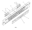
FIG. 2 is an exploded view in perspective of the assembly for extruding a tire component in accordance with the invention. -
FIG. 3 is another exploded view in perspective of the assembly offigure 1 from another point of view. -
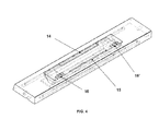
FIG. 4 is a perspective view of the assembly offigures 1 and2 in an assembled state. -
FIGS. 5 and 6 are perspective views of the die components of the assembly illustrated infigures 1 ,2 and3 . -
FIG. 7 is a photograph of a cross-section of a shoulder wedge produced by a method in accordance with the invention. - The concepts "cap", "base", "top" and "bottom" used in this description relate to the shape of the shoulder wedge to be extruded where the flat portion of the shoulder wedge corresponds to the bottom or base portion thereof and the wedge portion corresponds to the cap or top portion. For the sake of clarity the exploded view in
Figure 2 shows an extruder assembly in an orientation where the bottom flat portion of the shoulder wedge is directed upwardly. The concepts "cap" and "base" relate therefore to lower elements inFigure 2 and "top" and "bottom" correspond to upper elements. The extruder assembly as illustrated inFigures 2 and3 comprises a splice bar 1, aholder 2 and adie 3. The splice bar 1 is designed to guide and unite two separate streams of rubber. The splice bar is an elongated element with a fastening andpositioning block 4, 4' at each end. The cross section of these blocks is trapezoid. Eachblock 4, 4' comprises abottom surface 5, 5', afront surface 6, 6', a top surface and a rear surface. The cross section of the guiding section of the bar is triangular. The base surface C is designed to guide a first stream of rubber whereas the cap surface D is designed to guide a second stream of rubber. The rear surface of the guiding section is in the same plane as the rear surface of theblocks 4 and 4'. This surface is designed to come in contact with a corresponding surface of an extruder able to produce two distinct streams of rubber. The cap and base surfaces of the guiding section of the splice bar intersect downstream in order to bring together and unite the two separate streams of rubber. - The
holder 2 is shaped as a rectangular plate comprising an opening. This opening is shaped for receiving the splice bar 1. Thebottom surfaces 5, 5' and top surfaces of theblocks 4, 4' come in thrust engagement with corresponding surfaces of the opening. - The die
element 3 is generally shaped as a plate comprising ashaped opening 11 through which the tire component is extruded. Theholder 2 and thedie element 3 are designed to come into engagement when assembled. To that end theholder 2 comprises a recess corresponding to the outer surface of the die so that the die can be very precisely positioned relative to the holder and the splice bar. When the three elements, i.e. the splice bar, the holder and the die element, are assembled together, thefront surfaces 6 and 6' of the splice bar 1 are in contact with the rear surface of the die. - The
die element 3 is made of two parts, namely thedie 10 and theback die 9. This construction is better illustrated inFigures 5 and 6 . Thedie 10 is designed as a rectangular plate with arecess 11 at one of its longer edges. Thisrecess 11 provides the cross sectional shape of the tire element to be extruded. Thedie 10 comprises also a series of undercut sections as illustrated by thenumerals figure 5 . The back die 9 is shaped as a rectangle, a longer edge thereof coming into contact with the recessed edge of the die 10 thereby closing the recessed area and forming a part of the shapedopening 11. - Each
block 6 and 6' of the splice bar is specially shaped to form a groove or recess in the bottom surfaces 5 and 5' and thefront surfaces 6 and 6'. These grooves are illustrated by the letter A inFigure 2 . They create with the counter surfaces of theholder 2 and thedie element 3, i.e. the surfaces of the holder and the die element coming into contact with the bottom and front surfaces of the blocks when the splice bar, the holder and the die element are assembled together, for each side of the splice bar a lateral or auxiliary passage. This lateral passage is curved and guides an auxiliary stream of rubber derived from the rubber stream normally guided by the upper surface of the guiding section of the splice bar downward to a lower section of theholder 2. - When reaching the lower section of the
holder 2, the auxiliary stream of rubber is forced through therecesses 8 and 8' formed at each end of alip 7 as better illustrated inFigure 3 . Thefront surfaces 6 and 6' on each side of the lateral passages A come into contact with corresponding surfaces of thedie element 3 as is better illustrated inFigures 3 and4 . Indeed, thedie element 3 is designed such that the thickness of the back die 9 corresponds to the thickness of the die 10 whereas a series ofundercut regions recesses 8 and 8' to the center area and the edge of therecess 11 defining the shaped opening of the die. This stream of rubber is illustrated by the arrows B inFigure 2 . - The
holder 2 comprises anelongated lip 7 arranged horizontally at the cap side of its general opening receiving the splice bar. Thislip 7 is integrally formed with theholder 2 and presents a front side, i.e. a side in front of the splice bar, with a general plane corresponding to the general plane of the top surfaces of theblocks 4 and 4' of the splice bar when this latter is assembled in the holder. The edge of the lip is parallel to the longitudinal axis of the splice bar and of the holder and the die element and comes into contact with the die 10 at a slight distance from the top edge of therecess 11. This is better illustrated inFigure 4 where the inclined lip, the die and its shaped opening are visible in transparency and are represented by the dashed lines. The back side of thelip 7 defines a horizontal passage for the auxiliary stream of rubber which is illustrated by the arrows B inFigure 2 . When the splice bar and the die element are assembled in the holder, thelip 7 is in contact with thedie 3 whereas the undercutareas 12 define a slot for the passage of the auxiliary streams of rubber coming from both ends of the lip and colliding at the center of the horizontal passage defined by the back side of thelip 7 and thedie 10. The rubber is then forced upwardly through this slot and joins the main stream of rubber coming from the splice bar and extruded through the shapedopening 11. It then migrates together with the main stream through theopening 11 and is then coextruded. - The functions of the above described assembly for an extruder and the extrusion process it achieves are explained more in details here below:
- The assembly comprising the described splice bar 1,
holder 2 and die 3 is designed to be mounted on a dual extruder, i.e. an extruder able to generate two independent streams of rubber compound, typically a two screw extruder. An extruder with more than two screws would also be suitable for the described assembly but this would not take the advantage of the fact that the described assembly and method allow the extrusion of a tire component with a coating on both its upper and lower surfaces while using only two distinct streams of rubber, i.e. as produced by a dual screw extruder. - A first stream of a first rubber compound is generated by the extruder and is fed to the base side of the splice bar whereas a second stream of a second rubber compound is fed to the cap side of the splice bar. The first stream is guided by the base surface C of the splice bar and the corresponding surface of the holder. Similarly the second stream is guided by the cap surface D of the splice bar and the corresponding surface of the holder. When exiting the splice bar, both streams are united to a main stream composed of two adhered layers. The inlets of the assembly for the two streams of rubber compound as well as the two auxiliary passages defined by the splice bar and the holder are well illustrated in
Figure 4 with thenumerals inlets lower inlet 15 for the second stream is much thinner than theupper inlet 14 for the first stream. As illustrated inFigure 4 , the intersection line of the cap and base surfaces of the splice bar is approximately at the level of the edge of the back die 9 which defines the shapedopening 11. This intersection is in fact slightly lower than this edge of the back die 9 in order to extrude a thin layer of the second rubber compound on the upper surface of the tire element. - In parallel to the extrusion of the main stream composed of the two adhered layers of rubber compounds, an auxiliary stream of the second rubber compound is guided through the passages indicated by the arrows A and B in
Figure 2 . The twoinlets 16 and 16' of the lateral passages A are illustrated inFigure 4 and are positioned approximately at the level of theinlet 15 of the lower passage in order to be fed by the extruder with the second rubber compound. After entry in the assembly, the second rubber compound streams then through the passages A to therecesses 8 and 8' of the holder 1 and then along the horizontal passage between the back side of thelip 7 and the die along the arrows B. The two horizontal streams meet at a center region of the horizontal passage and are forced through the slot defined by the back side of thelip 7 and the undercutregions 12 of the die 10, thereby joining and feeding the main stream composed of a lower thin layer of the second rubber compound and an upper thicker layer of the first compound for the body of the tire element. The auxiliary stream of the second rubber compound migrates to the upper layer of the main stream which is then extruded through theopening 11. This results in a coating of the lower side of the tire element with the same compound as on the lower or bottom side while requiring only a dual extruder. The thickness of the upper or topcoating of compound depends on many factors like, for example, the viscosity of the compounds (i.e. the type of compound and the working temperature), the shape of the tire component to be extruded, ... For a defined shape and determined compounds and working temperature, this depends essentially on the extrusion speed and the shape and cross section of the slot defined by the back side of thelip 7 and the undercutregions 12 of thedie 10. -
Figure 7 illustrates a shoulder wedge produced by the above described assembly. As it can be seen fromFigures 5 and 7 , the shape of the shoulder wedge corresponds to the shapedopening 11 of thedie element 3 of the extruder described here above. Thebody 19 of the shoulder wedge is made of the first rubber compound fed through the inlet 14 (figure 4 ) of the extruder assembly and guided by the cap surface D of the splice bar 1. The first rubber compound is typically an OTR carcass compound. Thebody 19 is covered or coated with a thin layer of the second rubber compound at this periphery, i.e. athin layer 17 at its lower or bottom flat side and asecond layer 18 at its upper or top curved side. The second compound is formulated to provide a smear of high tack compound around the shoulder wedge for facilitation the assembly with other tire components, typically a OTR smear compound. Thelower layer 17 originates from the second stream fed through theinlet 15 and guided by the base surface C of the splice bar 1. Theupper layer 18 is fed by the auxiliary or lateral passages and originates also from the second stream fed through theauxiliary inlets 16 and 16' (Figure 4 ) and guided by grooves of the splice bar 1 and by thelip 7 of the holder 2 (Figure 3 ). - In an alternative mode of carrying out the invention, a single lateral passage for an auxiliary stream of rubber can be used.
- The assembly elements, i.e. the splice bar, the holder and the die are typically made of steel and formed by machining but alternative ways known those skilled in the art for shaping these elements as described here above can also be considered.
Claims (15)
- An assembly for a tire component extruder, the assembly comprising:a splice bar (1) designed for guiding and uniting a first stream of a first rubber compound and a second stream of a second rubber compound;a die (3) designed for being positioned downstream of the splice bar (1), the die (3) comprising a shaped (11) opening through which the united streams of the first and second compounds are extrudable for forming the tire component;an auxiliary channel in communication with the second stream of the second rubber compound and with a feeding end between the splice bar (1) and the die (3) at the vicinity of the united first and second streams of rubber compounds at the first stream side in order to be able to feed the united streams at a side opposite to the second stream with an auxiliary stream of the second compound before extrusion through the die (3).
- The assembly according to claim 1, wherein the channel is designed for being in communication with the second stream of the second rubber compound upstream of the splice bar (1).
- The assembly according to claim 1 or 2, wherein the channel comprises at least a lateral passage provided in the splice bar (1) in communication with the second stream.
- The assembly according to at least one of the previous claims, wherein the feeding end of the channel comprises a slot.
- The assembly according to claim 4, further comprising a lip designed to be positioned between the splice bar (1) and the die (3) and inclined towards the die (3) such that the lip guides the united streams at the first stream side towards the die (3), the slot being arranged downstream of the lip.
- The assembly according to claim 5, further comprising a holder comprising an opening designed for receiving the splice bar (1) on one side and the die (3) on the other side, wherein the lip is provided on the holder in the opening.
- The assembly according to claim 6, wherein the downstream side of the lip and the die form a passage of the auxiliary channel.
- The assembly according to claim 7, wherein the die (3) comprises a plate with a shaped opening corresponding to the cross-section of the tire component to be extruded, the edge of the lip being distant from the plate in the area of said shaped opening in order to form the slot for feeding the auxiliary stream of the second rubber compound.
- The assembly according to claim 8, wherein the splice bar (1) comprises at each extremity a positioning block with at least two surfaces coming into contact with the holder when the splice bar (1) is positioned in the holder, wherein at least one of the blocks comprises a recess (8, 8') formed in the at least two surfaces, the recess (8, 8') forming with the holder a curved passage of the auxiliary channel for guiding the second rubber compound from the second stream upstream of the splice bar to the passage between the lip and the die (3).
- The assembly according to claim 9, wherein the curved passage communicates with the passage between the lip and the die (3) at a lateral end of the lip for feeding the passage between the lip and the die (3) with the auxiliary stream of second rubber compound.
- The assembly according to claim 10, wherein the opening of the holder comprises a recess at a lateral end of the lip for communicating the curved passage with the passage between the lip and the die (3).
- The assembly according to at least one of the previous claims, wherein the die plate is slightly recessed at an area in the vicinity of the shaped opening on the side of the plate coming into contact with the holder, the recessed area forming the slot between the die (3) and the lip for the auxiliary stream of the second rubber compound.
- The assembly according to claim 12, wherein the die (3) comprises a first plate with a first recessed edge and a second plate with a second edge to be positioned against the first edge, the first recessed edge and the second edge forming the shaped opening of the die.
- A method for producing a tire component by extrusion of a rubber compound through an extruder, the method comprising the steps of:extruding a first rubber compound through an extruder for forming the tire component and simultaneously extruding a second rubber compound through the extruder for forming a coating at the periphery of the cross sectional area of the tire component during extrusion thereof.
- The method according to claim 14, wherein the extruding step comprises:guiding and uniting a first stream of the first rubber compound with a second stream of the second rubber compound and simultaneously guiding an auxiliary stream of the second rubber compound to the united first and second streams at the first stream side opposite to the second stream in order to join the auxiliary stream to the united first and second streams;extruding the united first, second and auxiliary streams of compound through an extrusion die for forming the tire component, such that at least two opposite sides of the tire component are coated with the second compound.
Applications Claiming Priority (1)
| Application Number | Priority Date | Filing Date | Title |
|---|---|---|---|
| US12/360,998 US8016580B2 (en) | 2009-01-28 | 2009-01-28 | Assembly and a method for extruding a tire component |
Publications (3)
| Publication Number | Publication Date |
|---|---|
| EP2213442A2 true EP2213442A2 (en) | 2010-08-04 |
| EP2213442A3 EP2213442A3 (en) | 2011-09-28 |
| EP2213442B1 EP2213442B1 (en) | 2015-11-04 |
Family
ID=42112270
Family Applications (1)
| Application Number | Title | Priority Date | Filing Date |
|---|---|---|---|
| EP10151540.1A Not-in-force EP2213442B1 (en) | 2009-01-28 | 2010-01-25 | An assembly and a method for extruding a tire component |
Country Status (4)
| Country | Link |
|---|---|
| US (2) | US8016580B2 (en) |
| EP (1) | EP2213442B1 (en) |
| CN (1) | CN101817219B (en) |
| BR (1) | BRPI1000100A2 (en) |
Families Citing this family (3)
| Publication number | Priority date | Publication date | Assignee | Title |
|---|---|---|---|---|
| CN103935004A (en) * | 2014-04-16 | 2014-07-23 | 江苏通用科技股份有限公司 | Device for preventing reverse installation of preform die |
| FR3060435A1 (en) * | 2016-12-20 | 2018-06-22 | Compagnie Generale Des Etablissements Michelin | COEXTRUSION HEAD OF A COMPLEX RUBBER PROFILE INTENDED FOR THE MANUFACTURE OF A PNEUMATIC |
| CN112454858B (en) * | 2020-11-02 | 2022-06-21 | 青岛森麒麟轮胎股份有限公司 | Tire side pre-opening type and tire side extrusion production line |
Family Cites Families (23)
| Publication number | Priority date | Publication date | Assignee | Title |
|---|---|---|---|---|
| US2897543A (en) * | 1958-02-24 | 1959-08-04 | Goodrich Co B F | Multi-part extruder head |
| US3280427A (en) * | 1964-02-03 | 1966-10-25 | Cooper Tire & Rubber Co | Apparatus for extruding composite black and white rubber strips for white sidewall tires |
| US3486195A (en) * | 1967-01-18 | 1969-12-30 | Goodyear Tire & Rubber | Duplex extruder head |
| DE1729599C3 (en) * | 1967-11-02 | 1975-10-09 | Continental Gummi-Werke Ag, 3000 Hannover | Extrusion head for the extrusion of flat profile strands from different rubber compounds, in particular raw treads for pneumatic tires |
| DE1729608A1 (en) * | 1968-02-16 | 1971-07-01 | Continental Gummi Werke Ag | Spray head for tire treads |
| US4007069A (en) * | 1970-12-29 | 1977-02-08 | Bridgestone Tire Company Limited | Process for making radial tires |
| US4316195A (en) * | 1980-09-19 | 1982-02-16 | The United States Of America As Represented By The Secretary Of The Army | Rotating dual frequency range antenna system |
| DE3325017C2 (en) * | 1983-07-11 | 1985-11-28 | Continental Gummi-Werke Ag, 3000 Hannover | Press head for the production of flat, coherent profile strands from plastic rubber or plastic mixtures of various compositions |
| US4526528A (en) * | 1984-06-28 | 1985-07-02 | The Goodyear Tire & Rubber Company | Apparatus for forming a co-extrusion from extruded strips |
| US4556382A (en) * | 1984-10-11 | 1985-12-03 | The Firestone Tire & Rubber Company | Die assembly for tire tread extrudate |
| US4683095A (en) * | 1985-05-08 | 1987-07-28 | The Uniroyal Goodrich Tire Company | Early progressive junction extrusion process and system |
| DE3521643C1 (en) * | 1985-06-15 | 1986-07-03 | Hermann Berstorff Maschinenbau Gmbh, 3000 Hannover | Hinged extrusion head for the production of rubber or plastic flat profiles |
| US5705111A (en) * | 1987-12-31 | 1998-01-06 | American National Can Company | Methods for making multiple layer sheet materials |
| US5017118A (en) * | 1989-06-16 | 1991-05-21 | The Goodyear Tire & Rubber Company | Apparatus for forming a coextrusion from extruded strips |
| IT1290520B1 (en) * | 1997-04-03 | 1998-12-04 | Pirelli | EXTRUSION METHOD AND APPARATUS FOR MAKING TREAD BANDS FOR VEHICLE TIRES |
| US6645334B1 (en) * | 1999-01-26 | 2003-11-11 | The Goodyear Tire & Rubber Company | Tire manufacturing using a roll forming apparatus |
| US6808579B1 (en) * | 1999-09-20 | 2004-10-26 | The Goodyear Tire & Rubber Company | Bonding elastomeric articles |
| IT1321048B1 (en) * | 2000-11-07 | 2003-12-30 | Bridgestone Firestone Tech | METHOD AND DEVICE FOR THE CREATION OF A TWO-COMPONENT LAYER OF A TIRE. |
| ES2282373T3 (en) * | 2001-03-12 | 2007-10-16 | Bridgestone Corporation | TIRE. |
| JP4611551B2 (en) * | 2001-03-12 | 2011-01-12 | 株式会社ブリヂストン | Unvulcanized rubber extrusion apparatus and unvulcanized rubber extrusion method |
| DE60229974D1 (en) * | 2001-05-16 | 2009-01-02 | Michelin Soc Tech | DEVICE FOR COEXTRUDING RUBBER MIXTURES |
| JP4163017B2 (en) * | 2003-01-28 | 2008-10-08 | 横浜ゴム株式会社 | Tire tread rubber molding equipment |
| KR100513240B1 (en) * | 2003-11-04 | 2005-09-07 | 금호타이어 주식회사 | Molding Extruder Die set of the Tire having a slope conductive ring |
-
2009
- 2009-01-28 US US12/360,998 patent/US8016580B2/en not_active Expired - Fee Related
-
2010
- 2010-01-18 BR BRPI1000100-0A patent/BRPI1000100A2/en not_active IP Right Cessation
- 2010-01-25 EP EP10151540.1A patent/EP2213442B1/en not_active Not-in-force
- 2010-01-28 CN CN2010101081991A patent/CN101817219B/en not_active Expired - Fee Related
-
2011
- 2011-08-09 US US13/205,716 patent/US8580173B2/en not_active Expired - Fee Related
Non-Patent Citations (1)
| Title |
|---|
| None |
Also Published As
| Publication number | Publication date |
|---|---|
| US8016580B2 (en) | 2011-09-13 |
| BRPI1000100A2 (en) | 2011-03-29 |
| US8580173B2 (en) | 2013-11-12 |
| CN101817219B (en) | 2012-12-05 |
| CN101817219A (en) | 2010-09-01 |
| US20110290412A1 (en) | 2011-12-01 |
| US20100186875A1 (en) | 2010-07-29 |
| EP2213442A3 (en) | 2011-09-28 |
| EP2213442B1 (en) | 2015-11-04 |
Similar Documents
| Publication | Publication Date | Title |
|---|---|---|
| EP3037241B1 (en) | Extruder die assembly and method of manufacturing a tire tread | |
| JP7072784B2 (en) | A method for manufacturing a plate-shaped body with a resin frame, and a plate-shaped body with a resin frame. | |
| US8580173B2 (en) | Assembly and a method for extruding a tire component | |
| US20110070325A1 (en) | Multiple-preformer die of extrusion mold for tire treads | |
| US9156338B2 (en) | Molding for vehicle and method for manufacturing same | |
| US5154870A (en) | Thermoplastic resin sheet manufacturing process and its apparatus | |
| KR101405064B1 (en) | Multi tread and multi tread extrusion preformer die | |
| CN104416879B (en) | The manufacturing method of rubber extrusion forming mold, tire building rubber components and tire building rubber components | |
| CN1251853C (en) | Method of forming a weatherseal from a replaceable insert | |
| US20120195996A1 (en) | Plastic material injection molding system | |
| EP3064384A1 (en) | Different thickness structure and production method therefor | |
| CN220904057U (en) | Door slot type die with sliding material additional function | |
| CN219686425U (en) | Aluminum plastic mold | |
| EP1426164A3 (en) | Method and apparatus for forming resin film | |
| CN205148853U (en) | Make up small cross section sealing strip bush of extruding by ebonite and sponge rubber | |
| MX2009000485A (en) | Dual-shot injection molded weatherseal. | |
| JP6862746B2 (en) | Manufacturing method of extruded rubber | |
| JP5844242B2 (en) | Preformer | |
| CN214000510U (en) | Mouth-shaped box for reinforcing combination of composite rubber | |
| CN218054831U (en) | Glass guide groove C post | |
| FR3132663B1 (en) | Method of manufacturing a vehicle interior trim element and interior trim element | |
| JP4622161B2 (en) | Manufacturing method for vehicle molding | |
| JP2560394B2 (en) | Molding manufacturing method | |
| EP0602320B1 (en) | A windshield molding for vehicles | |
| JP2020055242A (en) | Die plate and rubber extrusion equipment |
Legal Events
| Date | Code | Title | Description |
|---|---|---|---|
| PUAI | Public reference made under article 153(3) epc to a published international application that has entered the european phase |
Free format text: ORIGINAL CODE: 0009012 |
|
| AK | Designated contracting states |
Kind code of ref document: A2 Designated state(s): AT BE BG CH CY CZ DE DK EE ES FI FR GB GR HR HU IE IS IT LI LT LU LV MC MK MT NL NO PL PT RO SE SI SK SM TR |
|
| AX | Request for extension of the european patent |
Extension state: AL BA RS |
|
| PUAL | Search report despatched |
Free format text: ORIGINAL CODE: 0009013 |
|
| RIC1 | Information provided on ipc code assigned before grant |
Ipc: B29C 47/14 20060101ALI20110811BHEP Ipc: B29C 47/70 20060101AFI20110811BHEP Ipc: B29C 47/06 20060101ALI20110811BHEP Ipc: B29C 47/58 20060101ALN20110811BHEP |
|
| AK | Designated contracting states |
Kind code of ref document: A3 Designated state(s): AT BE BG CH CY CZ DE DK EE ES FI FR GB GR HR HU IE IS IT LI LT LU LV MC MK MT NL NO PL PT RO SE SI SK SM TR |
|
| AX | Request for extension of the european patent |
Extension state: AL BA RS |
|
| 17P | Request for examination filed |
Effective date: 20120328 |
|
| REG | Reference to a national code |
Ref country code: DE Ref legal event code: R079 Ref document number: 602010028700 Country of ref document: DE Free format text: PREVIOUS MAIN CLASS: B29C0047580000 Ipc: B29C0047700000 |
|
| GRAP | Despatch of communication of intention to grant a patent |
Free format text: ORIGINAL CODE: EPIDOSNIGR1 |
|
| INTG | Intention to grant announced |
Effective date: 20150619 |
|
| RIC1 | Information provided on ipc code assigned before grant |
Ipc: B29C 47/06 20060101ALI20150611BHEP Ipc: B29C 47/70 20060101AFI20150611BHEP Ipc: B29C 47/14 20060101ALI20150611BHEP Ipc: B29C 47/58 20060101ALN20150611BHEP |
|
| GRAS | Grant fee paid |
Free format text: ORIGINAL CODE: EPIDOSNIGR3 |
|
| GRAA | (expected) grant |
Free format text: ORIGINAL CODE: 0009210 |
|
| AK | Designated contracting states |
Kind code of ref document: B1 Designated state(s): AT BE BG CH CY CZ DE DK EE ES FI FR GB GR HR HU IE IS IT LI LT LU LV MC MK MT NL NO PL PT RO SE SI SK SM TR |
|
| REG | Reference to a national code |
Ref country code: GB Ref legal event code: FG4D |
|
| REG | Reference to a national code |
Ref country code: CH Ref legal event code: EP |
|
| REG | Reference to a national code |
Ref country code: AT Ref legal event code: REF Ref document number: 758889 Country of ref document: AT Kind code of ref document: T Effective date: 20151115 |
|
| REG | Reference to a national code |
Ref country code: IE Ref legal event code: FG4D |
|
| REG | Reference to a national code |
Ref country code: DE Ref legal event code: R096 Ref document number: 602010028700 Country of ref document: DE |
|
| REG | Reference to a national code |
Ref country code: FR Ref legal event code: PLFP Year of fee payment: 7 |
|
| REG | Reference to a national code |
Ref country code: NL Ref legal event code: MP Effective date: 20151104 |
|
| REG | Reference to a national code |
Ref country code: LT Ref legal event code: MG4D |
|
| REG | Reference to a national code |
Ref country code: AT Ref legal event code: MK05 Ref document number: 758889 Country of ref document: AT Kind code of ref document: T Effective date: 20151104 |
|
| PG25 | Lapsed in a contracting state [announced via postgrant information from national office to epo] |
Ref country code: HR Free format text: LAPSE BECAUSE OF FAILURE TO SUBMIT A TRANSLATION OF THE DESCRIPTION OR TO PAY THE FEE WITHIN THE PRESCRIBED TIME-LIMIT Effective date: 20151104 Ref country code: IS Free format text: LAPSE BECAUSE OF FAILURE TO SUBMIT A TRANSLATION OF THE DESCRIPTION OR TO PAY THE FEE WITHIN THE PRESCRIBED TIME-LIMIT Effective date: 20160304 Ref country code: NL Free format text: LAPSE BECAUSE OF FAILURE TO SUBMIT A TRANSLATION OF THE DESCRIPTION OR TO PAY THE FEE WITHIN THE PRESCRIBED TIME-LIMIT Effective date: 20151104 Ref country code: LT Free format text: LAPSE BECAUSE OF FAILURE TO SUBMIT A TRANSLATION OF THE DESCRIPTION OR TO PAY THE FEE WITHIN THE PRESCRIBED TIME-LIMIT Effective date: 20151104 Ref country code: ES Free format text: LAPSE BECAUSE OF FAILURE TO SUBMIT A TRANSLATION OF THE DESCRIPTION OR TO PAY THE FEE WITHIN THE PRESCRIBED TIME-LIMIT Effective date: 20151104 Ref country code: NO Free format text: LAPSE BECAUSE OF FAILURE TO SUBMIT A TRANSLATION OF THE DESCRIPTION OR TO PAY THE FEE WITHIN THE PRESCRIBED TIME-LIMIT Effective date: 20160204 |
|
| PG25 | Lapsed in a contracting state [announced via postgrant information from national office to epo] |
Ref country code: PL Free format text: LAPSE BECAUSE OF FAILURE TO SUBMIT A TRANSLATION OF THE DESCRIPTION OR TO PAY THE FEE WITHIN THE PRESCRIBED TIME-LIMIT Effective date: 20151104 Ref country code: PT Free format text: LAPSE BECAUSE OF FAILURE TO SUBMIT A TRANSLATION OF THE DESCRIPTION OR TO PAY THE FEE WITHIN THE PRESCRIBED TIME-LIMIT Effective date: 20160304 Ref country code: SE Free format text: LAPSE BECAUSE OF FAILURE TO SUBMIT A TRANSLATION OF THE DESCRIPTION OR TO PAY THE FEE WITHIN THE PRESCRIBED TIME-LIMIT Effective date: 20151104 Ref country code: LV Free format text: LAPSE BECAUSE OF FAILURE TO SUBMIT A TRANSLATION OF THE DESCRIPTION OR TO PAY THE FEE WITHIN THE PRESCRIBED TIME-LIMIT Effective date: 20151104 Ref country code: GR Free format text: LAPSE BECAUSE OF FAILURE TO SUBMIT A TRANSLATION OF THE DESCRIPTION OR TO PAY THE FEE WITHIN THE PRESCRIBED TIME-LIMIT Effective date: 20160205 Ref country code: BE Free format text: LAPSE BECAUSE OF NON-PAYMENT OF DUE FEES Effective date: 20160131 Ref country code: FI Free format text: LAPSE BECAUSE OF FAILURE TO SUBMIT A TRANSLATION OF THE DESCRIPTION OR TO PAY THE FEE WITHIN THE PRESCRIBED TIME-LIMIT Effective date: 20151104 Ref country code: AT Free format text: LAPSE BECAUSE OF FAILURE TO SUBMIT A TRANSLATION OF THE DESCRIPTION OR TO PAY THE FEE WITHIN THE PRESCRIBED TIME-LIMIT Effective date: 20151104 |
|
| PG25 | Lapsed in a contracting state [announced via postgrant information from national office to epo] |
Ref country code: CZ Free format text: LAPSE BECAUSE OF FAILURE TO SUBMIT A TRANSLATION OF THE DESCRIPTION OR TO PAY THE FEE WITHIN THE PRESCRIBED TIME-LIMIT Effective date: 20151104 |
|
| REG | Reference to a national code |
Ref country code: DE Ref legal event code: R097 Ref document number: 602010028700 Country of ref document: DE |
|
| PG25 | Lapsed in a contracting state [announced via postgrant information from national office to epo] |
Ref country code: LU Free format text: LAPSE BECAUSE OF FAILURE TO SUBMIT A TRANSLATION OF THE DESCRIPTION OR TO PAY THE FEE WITHIN THE PRESCRIBED TIME-LIMIT Effective date: 20160125 Ref country code: EE Free format text: LAPSE BECAUSE OF FAILURE TO SUBMIT A TRANSLATION OF THE DESCRIPTION OR TO PAY THE FEE WITHIN THE PRESCRIBED TIME-LIMIT Effective date: 20151104 Ref country code: DK Free format text: LAPSE BECAUSE OF FAILURE TO SUBMIT A TRANSLATION OF THE DESCRIPTION OR TO PAY THE FEE WITHIN THE PRESCRIBED TIME-LIMIT Effective date: 20151104 Ref country code: RO Free format text: LAPSE BECAUSE OF FAILURE TO SUBMIT A TRANSLATION OF THE DESCRIPTION OR TO PAY THE FEE WITHIN THE PRESCRIBED TIME-LIMIT Effective date: 20151104 Ref country code: SM Free format text: LAPSE BECAUSE OF FAILURE TO SUBMIT A TRANSLATION OF THE DESCRIPTION OR TO PAY THE FEE WITHIN THE PRESCRIBED TIME-LIMIT Effective date: 20151104 Ref country code: SK Free format text: LAPSE BECAUSE OF FAILURE TO SUBMIT A TRANSLATION OF THE DESCRIPTION OR TO PAY THE FEE WITHIN THE PRESCRIBED TIME-LIMIT Effective date: 20151104 |
|
| REG | Reference to a national code |
Ref country code: CH Ref legal event code: PL |
|
| PLBE | No opposition filed within time limit |
Free format text: ORIGINAL CODE: 0009261 |
|
| STAA | Information on the status of an ep patent application or granted ep patent |
Free format text: STATUS: NO OPPOSITION FILED WITHIN TIME LIMIT |
|
| PG25 | Lapsed in a contracting state [announced via postgrant information from national office to epo] |
Ref country code: MC Free format text: LAPSE BECAUSE OF FAILURE TO SUBMIT A TRANSLATION OF THE DESCRIPTION OR TO PAY THE FEE WITHIN THE PRESCRIBED TIME-LIMIT Effective date: 20151104 |
|
| 26N | No opposition filed |
Effective date: 20160805 |
|
| GBPC | Gb: european patent ceased through non-payment of renewal fee |
Effective date: 20160204 |
|
| PG25 | Lapsed in a contracting state [announced via postgrant information from national office to epo] |
Ref country code: CH Free format text: LAPSE BECAUSE OF NON-PAYMENT OF DUE FEES Effective date: 20160131 Ref country code: LI Free format text: LAPSE BECAUSE OF NON-PAYMENT OF DUE FEES Effective date: 20160131 |
|
| REG | Reference to a national code |
Ref country code: IE Ref legal event code: MM4A |
|
| PG25 | Lapsed in a contracting state [announced via postgrant information from national office to epo] |
Ref country code: SI Free format text: LAPSE BECAUSE OF FAILURE TO SUBMIT A TRANSLATION OF THE DESCRIPTION OR TO PAY THE FEE WITHIN THE PRESCRIBED TIME-LIMIT Effective date: 20151104 |
|
| PG25 | Lapsed in a contracting state [announced via postgrant information from national office to epo] |
Ref country code: BE Free format text: LAPSE BECAUSE OF FAILURE TO SUBMIT A TRANSLATION OF THE DESCRIPTION OR TO PAY THE FEE WITHIN THE PRESCRIBED TIME-LIMIT Effective date: 20151104 |
|
| REG | Reference to a national code |
Ref country code: FR Ref legal event code: PLFP Year of fee payment: 8 |
|
| PG25 | Lapsed in a contracting state [announced via postgrant information from national office to epo] |
Ref country code: GB Free format text: LAPSE BECAUSE OF NON-PAYMENT OF DUE FEES Effective date: 20160204 Ref country code: IE Free format text: LAPSE BECAUSE OF NON-PAYMENT OF DUE FEES Effective date: 20160125 |
|
| PG25 | Lapsed in a contracting state [announced via postgrant information from national office to epo] |
Ref country code: MT Free format text: LAPSE BECAUSE OF FAILURE TO SUBMIT A TRANSLATION OF THE DESCRIPTION OR TO PAY THE FEE WITHIN THE PRESCRIBED TIME-LIMIT Effective date: 20151104 |
|
| REG | Reference to a national code |
Ref country code: FR Ref legal event code: PLFP Year of fee payment: 9 |
|
| PG25 | Lapsed in a contracting state [announced via postgrant information from national office to epo] |
Ref country code: CY Free format text: LAPSE BECAUSE OF FAILURE TO SUBMIT A TRANSLATION OF THE DESCRIPTION OR TO PAY THE FEE WITHIN THE PRESCRIBED TIME-LIMIT Effective date: 20151104 Ref country code: HU Free format text: LAPSE BECAUSE OF FAILURE TO SUBMIT A TRANSLATION OF THE DESCRIPTION OR TO PAY THE FEE WITHIN THE PRESCRIBED TIME-LIMIT; INVALID AB INITIO Effective date: 20100125 |
|
| PG25 | Lapsed in a contracting state [announced via postgrant information from national office to epo] |
Ref country code: MK Free format text: LAPSE BECAUSE OF FAILURE TO SUBMIT A TRANSLATION OF THE DESCRIPTION OR TO PAY THE FEE WITHIN THE PRESCRIBED TIME-LIMIT Effective date: 20151104 Ref country code: TR Free format text: LAPSE BECAUSE OF FAILURE TO SUBMIT A TRANSLATION OF THE DESCRIPTION OR TO PAY THE FEE WITHIN THE PRESCRIBED TIME-LIMIT Effective date: 20151104 Ref country code: MT Free format text: LAPSE BECAUSE OF FAILURE TO SUBMIT A TRANSLATION OF THE DESCRIPTION OR TO PAY THE FEE WITHIN THE PRESCRIBED TIME-LIMIT Effective date: 20160131 |
|
| PG25 | Lapsed in a contracting state [announced via postgrant information from national office to epo] |
Ref country code: BG Free format text: LAPSE BECAUSE OF FAILURE TO SUBMIT A TRANSLATION OF THE DESCRIPTION OR TO PAY THE FEE WITHIN THE PRESCRIBED TIME-LIMIT Effective date: 20151104 |
|
| REG | Reference to a national code |
Ref country code: DE Ref legal event code: R079 Ref document number: 602010028700 Country of ref document: DE Free format text: PREVIOUS MAIN CLASS: B29C0047700000 Ipc: B29C0048695000 |
|
| PGFP | Annual fee paid to national office [announced via postgrant information from national office to epo] |
Ref country code: IT Payment date: 20200114 Year of fee payment: 11 |
|
| PGFP | Annual fee paid to national office [announced via postgrant information from national office to epo] |
Ref country code: FR Payment date: 20211217 Year of fee payment: 13 |
|
| PG25 | Lapsed in a contracting state [announced via postgrant information from national office to epo] |
Ref country code: IT Free format text: LAPSE BECAUSE OF NON-PAYMENT OF DUE FEES Effective date: 20210125 |
|
| PGFP | Annual fee paid to national office [announced via postgrant information from national office to epo] |
Ref country code: DE Payment date: 20211130 Year of fee payment: 13 |
|
| REG | Reference to a national code |
Ref country code: DE Ref legal event code: R119 Ref document number: 602010028700 Country of ref document: DE |
|
| PG25 | Lapsed in a contracting state [announced via postgrant information from national office to epo] |
Ref country code: DE Free format text: LAPSE BECAUSE OF NON-PAYMENT OF DUE FEES Effective date: 20230801 |
|
| PG25 | Lapsed in a contracting state [announced via postgrant information from national office to epo] |
Ref country code: FR Free format text: LAPSE BECAUSE OF NON-PAYMENT OF DUE FEES Effective date: 20230131 |