EP2213329A2 - Lead assembly with porous poylethylene cover and method - Google Patents
Lead assembly with porous poylethylene cover and method Download PDFInfo
- Publication number
- EP2213329A2 EP2213329A2 EP10151580A EP10151580A EP2213329A2 EP 2213329 A2 EP2213329 A2 EP 2213329A2 EP 10151580 A EP10151580 A EP 10151580A EP 10151580 A EP10151580 A EP 10151580A EP 2213329 A2 EP2213329 A2 EP 2213329A2
- Authority
- EP
- European Patent Office
- Prior art keywords
- piece
- polyethylene
- lead assembly
- cover
- porous polyethylene
- Prior art date
- Legal status (The legal status is an assumption and is not a legal conclusion. Google has not performed a legal analysis and makes no representation as to the accuracy of the status listed.)
- Withdrawn
Links
- 238000000034 method Methods 0.000 title description 36
- -1 polyethylene Polymers 0.000 claims abstract description 150
- 239000004698 Polyethylene Substances 0.000 claims abstract description 148
- 229920000573 polyethylene Polymers 0.000 claims abstract description 148
- 239000011148 porous material Substances 0.000 claims abstract description 62
- 239000000463 material Substances 0.000 claims description 57
- 239000004020 conductor Substances 0.000 claims description 11
- 239000004699 Ultra-high molecular weight polyethylene Substances 0.000 claims description 6
- 239000000126 substance Substances 0.000 claims description 6
- 229920000785 ultra high molecular weight polyethylene Polymers 0.000 claims description 6
- 230000002401 inhibitory effect Effects 0.000 claims description 3
- KFZMGEQAYNKOFK-UHFFFAOYSA-N Isopropanol Chemical compound CC(C)O KFZMGEQAYNKOFK-UHFFFAOYSA-N 0.000 description 6
- 239000003795 chemical substances by application Substances 0.000 description 6
- 238000010438 heat treatment Methods 0.000 description 6
- 229920000642 polymer Polymers 0.000 description 6
- 238000000429 assembly Methods 0.000 description 5
- 230000000712 assembly Effects 0.000 description 5
- 238000005553 drilling Methods 0.000 description 5
- 238000004519 manufacturing process Methods 0.000 description 5
- 239000002202 Polyethylene glycol Substances 0.000 description 4
- 238000000151 deposition Methods 0.000 description 4
- 229920001223 polyethylene glycol Polymers 0.000 description 4
- 229920001343 polytetrafluoroethylene Polymers 0.000 description 4
- 230000008467 tissue growth Effects 0.000 description 4
- LFQSCWFLJHTTHZ-UHFFFAOYSA-N Ethanol Chemical compound CCO LFQSCWFLJHTTHZ-UHFFFAOYSA-N 0.000 description 3
- OKKJLVBELUTLKV-UHFFFAOYSA-N Methanol Chemical compound OC OKKJLVBELUTLKV-UHFFFAOYSA-N 0.000 description 3
- 238000012544 monitoring process Methods 0.000 description 3
- 238000000623 plasma-assisted chemical vapour deposition Methods 0.000 description 3
- 239000004810 polytetrafluoroethylene Substances 0.000 description 3
- 230000004936 stimulating effect Effects 0.000 description 3
- VVJKKWFAADXIJK-UHFFFAOYSA-N Allylamine Chemical compound NCC=C VVJKKWFAADXIJK-UHFFFAOYSA-N 0.000 description 2
- LYCAIKOWRPUZTN-UHFFFAOYSA-N Ethylene glycol Chemical compound OCCO LYCAIKOWRPUZTN-UHFFFAOYSA-N 0.000 description 2
- 210000003748 coronary sinus Anatomy 0.000 description 2
- 230000008021 deposition Effects 0.000 description 2
- 238000005304 joining Methods 0.000 description 2
- 230000037361 pathway Effects 0.000 description 2
- 229920001296 polysiloxane Polymers 0.000 description 2
- 239000011118 polyvinyl acetate Substances 0.000 description 2
- 238000005245 sintering Methods 0.000 description 2
- 238000004804 winding Methods 0.000 description 2
- SMZOUWXMTYCWNB-UHFFFAOYSA-N 2-(2-methoxy-5-methylphenyl)ethanamine Chemical compound COC1=CC=C(C)C=C1CCN SMZOUWXMTYCWNB-UHFFFAOYSA-N 0.000 description 1
- NIXOWILDQLNWCW-UHFFFAOYSA-N 2-Propenoic acid Natural products OC(=O)C=C NIXOWILDQLNWCW-UHFFFAOYSA-N 0.000 description 1
- 102100026827 Protein associated with UVRAG as autophagy enhancer Human genes 0.000 description 1
- 101710102978 Protein associated with UVRAG as autophagy enhancer Proteins 0.000 description 1
- 210000001124 body fluid Anatomy 0.000 description 1
- 239000010839 body fluid Substances 0.000 description 1
- 238000005229 chemical vapour deposition Methods 0.000 description 1
- 238000003618 dip coating Methods 0.000 description 1
- 229920000295 expanded polytetrafluoroethylene Polymers 0.000 description 1
- 238000000605 extraction Methods 0.000 description 1
- WGCNASOHLSPBMP-UHFFFAOYSA-N hydroxyacetaldehyde Natural products OCC=O WGCNASOHLSPBMP-UHFFFAOYSA-N 0.000 description 1
- 239000007943 implant Substances 0.000 description 1
- 230000008018 melting Effects 0.000 description 1
- 238000002844 melting Methods 0.000 description 1
- 210000005036 nerve Anatomy 0.000 description 1
- 230000000926 neurological effect Effects 0.000 description 1
- 239000002245 particle Substances 0.000 description 1
- 239000002861 polymer material Substances 0.000 description 1
- 238000005507 spraying Methods 0.000 description 1
Images


Classifications
-
- A—HUMAN NECESSITIES
- A61—MEDICAL OR VETERINARY SCIENCE; HYGIENE
- A61N—ELECTROTHERAPY; MAGNETOTHERAPY; RADIATION THERAPY; ULTRASOUND THERAPY
- A61N1/00—Electrotherapy; Circuits therefor
- A61N1/02—Details
- A61N1/04—Electrodes
- A61N1/05—Electrodes for implantation or insertion into the body, e.g. heart electrode
- A61N1/056—Transvascular endocardial electrode systems
- A61N1/0565—Electrode heads
-
- A—HUMAN NECESSITIES
- A61—MEDICAL OR VETERINARY SCIENCE; HYGIENE
- A61N—ELECTROTHERAPY; MAGNETOTHERAPY; RADIATION THERAPY; ULTRASOUND THERAPY
- A61N1/00—Electrotherapy; Circuits therefor
- A61N1/02—Details
- A61N1/04—Electrodes
- A61N1/05—Electrodes for implantation or insertion into the body, e.g. heart electrode
- A61N1/056—Transvascular endocardial electrode systems
-
- A—HUMAN NECESSITIES
- A61—MEDICAL OR VETERINARY SCIENCE; HYGIENE
- A61N—ELECTROTHERAPY; MAGNETOTHERAPY; RADIATION THERAPY; ULTRASOUND THERAPY
- A61N1/00—Electrotherapy; Circuits therefor
- A61N1/02—Details
- A61N1/04—Electrodes
- A61N1/05—Electrodes for implantation or insertion into the body, e.g. heart electrode
- A61N1/056—Transvascular endocardial electrode systems
- A61N1/0563—Transvascular endocardial electrode systems specially adapted for defibrillation or cardioversion
-
- B—PERFORMING OPERATIONS; TRANSPORTING
- B29—WORKING OF PLASTICS; WORKING OF SUBSTANCES IN A PLASTIC STATE IN GENERAL
- B29C—SHAPING OR JOINING OF PLASTICS; SHAPING OF MATERIAL IN A PLASTIC STATE, NOT OTHERWISE PROVIDED FOR; AFTER-TREATMENT OF THE SHAPED PRODUCTS, e.g. REPAIRING
- B29C65/00—Joining or sealing of preformed parts, e.g. welding of plastics materials; Apparatus therefor
- B29C65/02—Joining or sealing of preformed parts, e.g. welding of plastics materials; Apparatus therefor by heating, with or without pressure
- B29C65/022—Particular heating or welding methods not otherwise provided for
-
- B—PERFORMING OPERATIONS; TRANSPORTING
- B29—WORKING OF PLASTICS; WORKING OF SUBSTANCES IN A PLASTIC STATE IN GENERAL
- B29C—SHAPING OR JOINING OF PLASTICS; SHAPING OF MATERIAL IN A PLASTIC STATE, NOT OTHERWISE PROVIDED FOR; AFTER-TREATMENT OF THE SHAPED PRODUCTS, e.g. REPAIRING
- B29C65/00—Joining or sealing of preformed parts, e.g. welding of plastics materials; Apparatus therefor
- B29C65/02—Joining or sealing of preformed parts, e.g. welding of plastics materials; Apparatus therefor by heating, with or without pressure
- B29C65/14—Joining or sealing of preformed parts, e.g. welding of plastics materials; Apparatus therefor by heating, with or without pressure using wave energy, i.e. electromagnetic radiation, or particle radiation
- B29C65/1403—Joining or sealing of preformed parts, e.g. welding of plastics materials; Apparatus therefor by heating, with or without pressure using wave energy, i.e. electromagnetic radiation, or particle radiation characterised by the type of electromagnetic or particle radiation
- B29C65/1412—Infrared [IR] radiation
-
- B—PERFORMING OPERATIONS; TRANSPORTING
- B29—WORKING OF PLASTICS; WORKING OF SUBSTANCES IN A PLASTIC STATE IN GENERAL
- B29C—SHAPING OR JOINING OF PLASTICS; SHAPING OF MATERIAL IN A PLASTIC STATE, NOT OTHERWISE PROVIDED FOR; AFTER-TREATMENT OF THE SHAPED PRODUCTS, e.g. REPAIRING
- B29C65/00—Joining or sealing of preformed parts, e.g. welding of plastics materials; Apparatus therefor
- B29C65/02—Joining or sealing of preformed parts, e.g. welding of plastics materials; Apparatus therefor by heating, with or without pressure
- B29C65/14—Joining or sealing of preformed parts, e.g. welding of plastics materials; Apparatus therefor by heating, with or without pressure using wave energy, i.e. electromagnetic radiation, or particle radiation
- B29C65/16—Laser beams
-
- B—PERFORMING OPERATIONS; TRANSPORTING
- B29—WORKING OF PLASTICS; WORKING OF SUBSTANCES IN A PLASTIC STATE IN GENERAL
- B29C—SHAPING OR JOINING OF PLASTICS; SHAPING OF MATERIAL IN A PLASTIC STATE, NOT OTHERWISE PROVIDED FOR; AFTER-TREATMENT OF THE SHAPED PRODUCTS, e.g. REPAIRING
- B29C65/00—Joining or sealing of preformed parts, e.g. welding of plastics materials; Apparatus therefor
- B29C65/74—Joining or sealing of preformed parts, e.g. welding of plastics materials; Apparatus therefor by welding and severing, or by joining and severing, the severing being performed in the area to be joined, next to the area to be joined, in the joint area or next to the joint area
- B29C65/747—Joining or sealing of preformed parts, e.g. welding of plastics materials; Apparatus therefor by welding and severing, or by joining and severing, the severing being performed in the area to be joined, next to the area to be joined, in the joint area or next to the joint area using other than mechanical means
- B29C65/7473—Joining or sealing of preformed parts, e.g. welding of plastics materials; Apparatus therefor by welding and severing, or by joining and severing, the severing being performed in the area to be joined, next to the area to be joined, in the joint area or next to the joint area using other than mechanical means using radiation, e.g. laser, for simultaneously welding and severing
-
- B—PERFORMING OPERATIONS; TRANSPORTING
- B29—WORKING OF PLASTICS; WORKING OF SUBSTANCES IN A PLASTIC STATE IN GENERAL
- B29K—INDEXING SCHEME ASSOCIATED WITH SUBCLASSES B29B, B29C OR B29D, RELATING TO MOULDING MATERIALS OR TO MATERIALS FOR MOULDS, REINFORCEMENTS, FILLERS OR PREFORMED PARTS, e.g. INSERTS
- B29K2023/00—Use of polyalkenes or derivatives thereof as moulding material
- B29K2023/04—Polymers of ethylene
- B29K2023/06—PE, i.e. polyethylene
-
- B—PERFORMING OPERATIONS; TRANSPORTING
- B29—WORKING OF PLASTICS; WORKING OF SUBSTANCES IN A PLASTIC STATE IN GENERAL
- B29K—INDEXING SCHEME ASSOCIATED WITH SUBCLASSES B29B, B29C OR B29D, RELATING TO MOULDING MATERIALS OR TO MATERIALS FOR MOULDS, REINFORCEMENTS, FILLERS OR PREFORMED PARTS, e.g. INSERTS
- B29K2105/00—Condition, form or state of moulded material or of the material to be shaped
- B29K2105/04—Condition, form or state of moulded material or of the material to be shaped cellular or porous
-
- B—PERFORMING OPERATIONS; TRANSPORTING
- B29—WORKING OF PLASTICS; WORKING OF SUBSTANCES IN A PLASTIC STATE IN GENERAL
- B29K—INDEXING SCHEME ASSOCIATED WITH SUBCLASSES B29B, B29C OR B29D, RELATING TO MOULDING MATERIALS OR TO MATERIALS FOR MOULDS, REINFORCEMENTS, FILLERS OR PREFORMED PARTS, e.g. INSERTS
- B29K2105/00—Condition, form or state of moulded material or of the material to be shaped
- B29K2105/25—Solid
- B29K2105/253—Preform
- B29K2105/256—Sheets, plates, blanks or films
-
- B—PERFORMING OPERATIONS; TRANSPORTING
- B29—WORKING OF PLASTICS; WORKING OF SUBSTANCES IN A PLASTIC STATE IN GENERAL
- B29L—INDEXING SCHEME ASSOCIATED WITH SUBCLASS B29C, RELATING TO PARTICULAR ARTICLES
- B29L2009/00—Layered products
-
- B—PERFORMING OPERATIONS; TRANSPORTING
- B29—WORKING OF PLASTICS; WORKING OF SUBSTANCES IN A PLASTIC STATE IN GENERAL
- B29L—INDEXING SCHEME ASSOCIATED WITH SUBCLASS B29C, RELATING TO PARTICULAR ARTICLES
- B29L2031/00—Other particular articles
- B29L2031/753—Medical equipment; Accessories therefor
Definitions
- This patent document pertains generally to medical device lead assemblies, and more particularly, but not by way of limitation, to porous polyethylene covers for a medical device lead assembly.
- Medical devices such as pacers and defibrillators typically include at least one lead assembly.
- a lead assembly typically includes at least one defibrillation electrode, such as a defibrillation coil.
- Some lead assemblies include a cover that extends over at least a portion of the outer surface of the lead assembly. A cover may extend over a defibrillation coil, for example. Covers are used, for example, to prevent tissue ingrowth.
- Expanded polytetrafluoroethylene has a high melting point (over 300 degrees C) and a high melt viscosity.
- the application of an PTFE cover to a defibrillation electrode can involve sintering at high temperatures. Improved coverings for lead assemblies are needed.
- An example lead assembly includes a lead body, a conductor extending through the lead body, an electrode coupled to the conductor, and a cover formed from porous polyethylene extending over the electrode.
- the cover includes a first section having tissue ingrowth allowing pores and a second section having tissue ingrowth inhibiting pores.
- the cover is formed from at least one piece of polyethylene wrapped around at least a portion of the electrode, the first section of the cover wrapped with a first tension, and the second section wrapped with a second tension that is different from the first tension.
- the piece of porous polyethylene is laser-sintered to itself.
- the cover extends over substantially all of the lead body.
- a lead assembly in another example, includes a lead body, a conductor extending through the lead body, an electrode coupled to the conductor, and a piece of mechanically stretched ultra high molecular weight polyethylene wrapped around at least a portion of the electrode.
- the piece of ultra high molecular weight polyethylene has a consistent pore size.
- the piece of mechanically stretched ultra high molecular weight polyethylene is hydrophilic.
- An example method includes wrapping a first piece of porous polyethylene material around a first portion of a lead assembly, and fusing a first portion of the first piece of porous polyethylene material to a second portion of the first piece of porous polyethylene material.
- the wrapping includes wrapping the piece of porous polyethylene material under tension and controlling the size of the pores in the polyethylene.
- controlling the size of the pores in the polyethylene includes adjusting the tension.
- the method further includes wrapping a second piece of porous polyethylene material around a second portion of the lead assembly, the second portion having pores that are larger than pores in the first piece of porous polyethylene material.
- the method further includes joining the second piece of porous polyethylene to the first piece of porous polyethylene.
- fusing the piece of porous polyethylene includes heating the piece of porous polyethylene to between 80 and 150 degrees.
- the method further includes hydrophilicly treating at least a portion of the first piece of porous polyethylene.
- a lead assembly includes a porous polyethylene cover extending over at least a portion of the length of the lead assembly.
- FIG. 1 shows an example system for monitoring and stimulating a heart that includes a lead assembly having a porous polyethylene cover.
- FIGS. 2 , 3A-3B , 4, 5 , and 6A-6B show lead assemblies and example porous polyethylene covers.
- FIG. 7 is a flowchart that illustrates a method of applying a cover.
- an example system for monitoring and stimulating a heart 105 includes a medical device 110 and at least one lead assembly.
- the lead assembly is a pacing lead, defibrillation lead, or neurological lead.
- the medical device 110 is a pacer, defibrillator, or stimulator.
- the medical device 110 is coupled to two lead assemblies, as shown in FIG. 1 .
- one lead assembly 115 extends into the right side of the heart.
- the other lead assembly 120 extends into the left side of the heart.
- Each lead assembly includes at least one porous polyethylene cover 125, 130.
- the medical device 110 is coupled to a single lead assembly that extends, for example, into either the right or left side of the heart.
- a lead assembly extends on or around the heart, or on or around a nerve truck or other anatomical target.
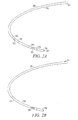
- FIG. 2A shows an example medical device lead assembly 205.
- the lead assembly 205 includes one or more conductors extending through a lumen in a lead body 21a.
- the lead body 210 is made of silicone.
- the lead body is a silicone tube.
- a proximal end 215 of the lead assembly 205 is connectable to a medical device.
- a distal end portion 220 of the lead assembly is implantable in, on, or around a heart.
- the conductors in the lead assembly are electrically coupled to one or more electrodes.
- the lead assembly includes a first defibrillation electrode 230, a second defibrillation electrode 235, and a sensing/pacing electrode 240.
- a porous polyethylene covering 245 extends over at least one of the defibrillation electrodes.
- a first covering 250 extends over the first defibrillation electrode 230 and a second covering 255 extends over the second defibrillation electrode 235.
- the coverings are shown partially cut-away in FIG. 2A to show the electrodes beneath the coverings.
- the coverings are spaced apart on the lead assembly.
- the coverings touch or overlap, and are optionally joined together.
- a single covering 260 extends over both the first defibrillation electrode 230 and the second defibrillation electrode 235, as shown in FIG. 2B .
- the thickness of the polyethylene covering is between 0.0001 and 0.010 inches, the width of the covering is between 0.1 and 8 inches, and the pore size is between 0.1 micron and 15 microns.
- the polyethylene covering shown in FIG. 2A or 2B has a tensile strength of about 1000 pounds per square inch (psi) and pore size of about 2 microns.
- a porous polyethylene covering is applied to an electrode in line with other manufacturing processes.
- polyethylene materials have a processing temperature of around 130-150° C, which allows application of the polyethylene covering in a manufacturing line.
- materials such as PTFE can have processing temperatures in excess of 300° C.
- a PTFE covering is typically added to a lead assembly in a post process. Forming a cover from polyethylene allows the cover to be applied in-line with other manufacturing steps because of the 130-150° C processing temperatures associated with polyethylene.
- polyethylene can be applied by spray coating, dip coating, plasma deposition, laser deposition, or chemical vapor deposition.
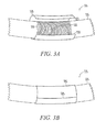
- a piece of porous polyethylene material 305 is wrapped around at least a portion of a lead assembly 315.
- the piece includes a first edge 325 and a second edge 330.
- the first edge 325 meets or overlaps with the second edge 330, as shown in FIG. 3B .
- the piece of porous polyethylene material 305 is wrapped around an electrode 310.
- the electrode 310 includes a wire 320 wrapped into a coil, and the polyethylene material covers the entire coil.
- the piece of porous polyethylene also extends over at least a portion of a lead body 335.
- the cover extends over most or all of the lead assembly.
- the polyethylene cover 305 is secured on the lead assembly, for example, by connecting the cover to itself.
- at least a portion of the polyethylene cover 305 is heated to fuse the porous polyethylene material to itself.
- the heating also conforms the polyethylene to the outer shape of the electrode or lead body.
- the polyethylene material 305 is sintered proximate the first edge 325 to hold the material 305 in a generally tubular shape that extends over the electrode, as shown in FIG. 3B .
- the porous polyethylene covering is sintered with a laser, infrared (IR) wand, heat gun, or oven.
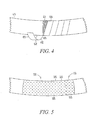
- a piece 405 of polyethylene material 406 is wrapped around a lead assembly 415 in a spiral.
- the piece 405 is wrapped around an electrode 410.
- a first edge 420 of the piece 405 meets or overlaps with a second edge 425 of the piece from a previous wrap around the lead assembly.
- the spiral-wrapped piece of polyethylene forms a polyethylene tube 430 that extends over the electrode.
- spiral-wrapped polyethylene material as shown in FIG. 4 extends past the electrode to cover a portion of the lead assembly, or all of the lead assembly. Covering the lead assembly protects the lead assembly and facilitates extraction, for example by limiting or preventing tissue ingrowth around portions of the lead.
- a polyethylene covering 505 includes pores 510.
- the size of the pores is exaggerated for the purpose of illustration.
- the pore size in the porous polyethylene covering is controlled to control tissue ingrowth into the covering.
- the pores 515 in a first portion 520 of the polyethylene covering 505 are smaller than the pores 525 in a second portion 530 of the polyethylene covering.
- a dotted line is provided FIG. 5 to distinguish the first portion 520 of the covering from the second portion 530.
- the pores 515 in the first portion 520 are large enough to allow at least some tissue ingrowth, and the pores 525 in the second portion 530 are small enough to substantially inhibit tissue ingrowth.
- the tissue ingrowth into the pores 515 in the first portion 520 secures the lead to body tissue.
- the covering 505 is formed around the lead assembly using the technique illustrated in FIGS. 3A-3B or the technique illustrated in FIG. 4 .
- the size of pores in the polyethylene material can be controlled using one or more of a variety of techniques.
- pieces of polyethylene material are manufactured to have differing pore sizes by controlling parameters such as tension or heat during the manufacturing process.
- different polyethylene pieces are used at different locations on the lead assembly to allow tissue growth at particular locations on the lead, such as at a distal end portion.
- pore size is controlled by adjusting tension applied to the polyethylene material as the material is assembled onto the lead assembly.
- a polyethylene cover is made using a spiral winding technique, as illustrated in FIG. 4 , and the pore size is controlled by varying the tension on the piece of material 305.
- pore size is varied through application of heat during or after the application of the polyethylene material to the electrode.
- two or more of the preceding techniques are used concurrently or sequentially to control the pore size at one or more locations in the polyethylene material.
- laser drilling is used to form pores in a specific size and pattern.
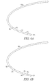
- a lead assembly 605 includes a first porous polyethylene cover 610 proximate a distal end portion 615 of the lead assembly and a second polyethylene cover 620 proximate a middle portion 625 of the lead assembly.
- the lead assembly includes a third cover 630 that extends between the first cover 610 and second cover 620.
- Other examples include additional polyethylene covers.
- covers extend over most or all of the outer surface of the lead assembly.
- some or all of the polyethylene covers are fused together using heat.
- the ends of adjacent covers are fused together using a laser.
- a portion of the polyethylene cover 610 proximate the distal end portion of the lead assembly 605 includes pores that are large enough to permit tissue growth.
- the tissue growth secures the distal end portion of the lead to local tissue, For example, when the lead is implanted in the heart, the tissue growth secures the distal end portion of the lead to the heart.
- pore size is controlled within one or both of the covers 610, 620, which allows for selective tissue ingrowth at locations on the cover.
- a cover 635 includes a first portion 640 that includes pores that are large enough to allow tissue ingrowth, and a second portion 645 that has pores that do not allow tissue ingrowth.
- the first portion 640 is formed having larger pores than the second portion 645 by varying parameters such as tension and/or heat during application of the polyethylene to the lead assembly.
- the first portion 640 is made from a separate piece of polyethylene material that has been pre-processed to have larger pores than the second portion 645. In an example, the separate piece is applied to the lead in a separate operation and then sintered to the second portion to form a continuous cover
- the covering is hydrophilicly treated.
- the covering is wetted using a plasma technique.
- the covering is wetted using a plasma-assisted chemical vapor deposition technique.
- the covering is treated using, glycol, acrylic acid, allyl amine, an alcohol such as isopropyl alcohol (IPA), ethanol, or methanol.
- the covering is treated with a laser after the covering is wetted to preserve the hydrophilic state of the covering.
- the wavelength, pulse duration, and/or power are adjusted to actuate the polymer surface and promote development of a hydrophilic state.
- a chemical hydrophilic treatment is used.
- the chemical hydrophilic treatment uses polyvinyl acetate (PVA) or polyethylene glycol (PEG).
- the pores in the polyethylene provide a conductive pathway for a defibrillation current.
- the polyethylene includes particles of conductive matter to make the covering itself conductive.
- a conductive material is deposited on the polyethylene to provide a conductive pathway for a defibrillation current.
- FIG. 7 is a flow chart that illustrates a method of applying a polyethylene material to a lead assembly.
- a piece of porous polyethylene material is wrapped around a first portion of a lead assembly.
- the stock polyethylene material is porous before it is wrapped.
- pores are created in the polyethylene when the polyethylene is wrapped.
- the size of the pores in the polyethylene is controlled by adjusting a tension in the polyethylene during wrapping. Applying a higher tension to the polyethylene results in more stretching of the material and larger pores.
- a first portion of the piece of porous polyethylene is fused to a second portion of the piece of polyethylene.
- the polyethylene is wrapped spirally onto the lead assembly, and adjacent portions of the material (i.e. adjacent windings) are fused together.
- the polyethylene is fused by heating, for example with a laser.
- the porous polyethylene is heated to between 80 and 150 degrees C.
- a second piece of porous polyethylene is wrapped around a second portion of the lead assembly.
- the second piece of polyethylene has pores that are larger than the pores in the first piece of porous polyethylene.
- the second piece of porous polyethylene is wrapped onto the lead assembly before the first piece of porous polyethylene is wrapped onto the lead assembly.
- the second piece of porous polyethylene is joined to the first piece of porous polyethylene.
- the second piece of porous polyethylene is fused to the first piece of porous polyethylene by heating the polyethylene, for example with a laser.
- a hydrophilic agent is deposited on one or both of the pieces of porous polyethylene.
- a hydrophilic agent is deposited in a plasma-assisted chemical vapor deposition process.
- hydrophilicly treating at least a portion of the piece of porous polyethylene includes treating the first piece of polyethylene with a laser.
- laser treating the porous polyethylene preserves hydrophilicity imparted by a hydrophilic agent.
- hydrophilicly treating at least a portion of the piece of porous polyethylene includes chemically treating the first piece of polyethylene.
- the chemical treatment preserves hydrophilicity imparted by a hydrophilic agent.
- the chemical hydrophilic treatment uses polyvinyl acetate (PVA) or polyethylene glycol (PEG).
- the polymer lead coverings or porous polyethylene coverings in the various embodiments discussed above include polymer lead coverings having varied material properties.
- the material properties vary within the cover.
- some or all of the cover is porous.
- all of the lead assembly is covered except a fixation mechanism at or near the distal tip, and a terminal that connects to a medical device.
- the strip of material is manufacture with regions of that have varying material properties before application to the lead assembly. When the strip material is wrapped on the lead assembly, the cover has regions having varied properties determined at least in part by the variations that are manufactured into the raw polymer material.
- the location on the lead assembly of regions having particular properties can be calculated using the diameter of the lead body, the width of the strip, and the stretching characteristics of the polymer.
- the material properties are varied in the cover by controlling parameters such as heat and tension in the polymer during the wrapping process.
- the material properties of the cover are modified after the cover is applied, for example by heating a portion of the cover.
- a combination of these four techniques is used to achieve a cover having the desired properties.
- a covering includes two or more covers, such as sheaths, that have different material properties.
- the covers are formed from the same polymer, but have different material properties, such as different stiffnesses or porosities.
- the two covers are joined together.
- a portion of a cover that is inserted through the coronary sinus during implant is more flexible than a portion of the cover that is not inserted through the coronary sinus.
- a portion of a cover near a distal end of a lead assembly includes pores sized to support tissue ingrowth, and other portions of the cover are not porous or includes pores sized to inhibit tissue ingrowth.
Landscapes
- Health & Medical Sciences (AREA)
- Heart & Thoracic Surgery (AREA)
- Engineering & Computer Science (AREA)
- Physics & Mathematics (AREA)
- Cardiology (AREA)
- Mechanical Engineering (AREA)
- Biomedical Technology (AREA)
- Nuclear Medicine, Radiotherapy & Molecular Imaging (AREA)
- Life Sciences & Earth Sciences (AREA)
- Animal Behavior & Ethology (AREA)
- General Health & Medical Sciences (AREA)
- Public Health (AREA)
- Veterinary Medicine (AREA)
- Radiology & Medical Imaging (AREA)
- Vascular Medicine (AREA)
- Electromagnetism (AREA)
- Optics & Photonics (AREA)
- Toxicology (AREA)
- Electrotherapy Devices (AREA)
- Prostheses (AREA)
- Pens And Brushes (AREA)
- Hybrid Cells (AREA)
Abstract
Description
- Benefit of priority is hereby claimed to
U.S. Patent Application Serial Number 111150,549, filed on June 10, 2005 , which application is herein incorporated by reference. - This patent document pertains generally to medical device lead assemblies, and more particularly, but not by way of limitation, to porous polyethylene covers for a medical device lead assembly.
- Medical devices such as pacers and defibrillators typically include at least one lead assembly. In a defibrillator, for example, a lead assembly typically includes at least one defibrillation electrode, such as a defibrillation coil. Some lead assemblies include a cover that extends over at least a portion of the outer surface of the lead assembly. A cover may extend over a defibrillation coil, for example. Covers are used, for example, to prevent tissue ingrowth.
- United States Published Patent Application No.
2003/0023294A1 describes
an expanded polytetrafluorethylene (sPTFE) cover. Expanded polytetrafluoroethylene has a high melting point (over 300 degrees C) and a high melt viscosity. The application of an PTFE cover to a defibrillation electrode can involve sintering at high temperatures. Improved coverings for lead assemblies are needed. - An example lead assembly includes a lead body, a conductor extending through the lead body, an electrode coupled to the conductor, and a cover formed from porous polyethylene extending over the electrode. In an example, the cover includes a first section having tissue ingrowth allowing pores and a second section having tissue ingrowth inhibiting pores. In an example, the cover is formed from at least one piece of polyethylene wrapped around at least a portion of the electrode, the first section of the cover wrapped with a first tension, and the second section wrapped with a second tension that is different from the first tension. In an example, the piece of porous polyethylene is laser-sintered to itself. In an example, the cover extends over substantially all of the lead body.
- In another example, a lead assembly includes a lead body, a conductor extending through the lead body, an electrode coupled to the conductor, and a piece of mechanically stretched ultra high molecular weight polyethylene wrapped around at least a portion of the electrode. In an example, the piece of ultra high molecular weight polyethylene has a consistent pore size. In an example, the piece of mechanically stretched ultra high molecular weight polyethylene is hydrophilic.
- An example method includes wrapping a first piece of porous polyethylene material around a first portion of a lead assembly, and fusing a first portion of the first piece of porous polyethylene material to a second portion of the first piece of porous polyethylene material. In an example, the wrapping includes wrapping the piece of porous polyethylene material under tension and controlling the size of the pores in the polyethylene. In an example, controlling the size of the pores in the polyethylene includes adjusting the tension. In an example, the method further includes wrapping a second piece of porous polyethylene material around a second portion of the lead assembly, the second portion having pores that are larger than pores in the first piece of porous polyethylene material. In an example, the method further includes joining the second piece of porous polyethylene to the first piece of porous polyethylene. In an example, fusing the piece of porous polyethylene includes heating the piece of porous polyethylene to between 80 and 150 degrees. In an example, the method further includes hydrophilicly treating at least a portion of the first piece of porous polyethylene.
- The following items are preferred embodiments of the invention.
- 1. A lead assembly comprising:
- a lead body;
- a conductor extending through the lead body;
- an electrode coupled to the conductor; and
- at least one porous polyethylene cover extending over the electrode.
- 2. The lead assembly of item 1, wherein the porous polyethylene cover is a mechanically stretched ultra high molecular weight polyethylene wrapped around at least a portion of the electrode.
- 3. The lead assembly of items 1 or 2,wherein a first portion of the cover has a first set of material properties and a second portion of the cover has a second set of material properties, at least one of the second set of material properties are different from at least one of the first set of material properties.
- 4. The lead assembly of any of the above items, wherein the cover includes a first section having tissue ingrowth allowing pores and a second section having tissue ingrowth inhibiting pores.
- 5. The lead assembly of item 4, wherein the cover is formed from at least one piece of polyethylene wrapped around at least a portion of the electrode, the first section of the cover wrapped with a first tension, and the second section wrapped with a second tension that is different from the first tension.
- 6. The lead assembly of item 5, wherein the piece of porous polyethylene is laser-sintered to itself.
- 7. The lead assembly any of items 5 or 6, wherein the piece of porous polyethylene is spirally wrapped around the electrode.
- 8. The lead assembly of any of items 4-7, where the first section is formed from a first piece of porous polyethylene and the second section is forked from a second piece of porous polyethylene, the first piece of porous polyethylene having larger pores than the second piece of porous polyethylene.
- 9. The lead assembly of item 8, wherein the first piece of porous polyethylene is joined to the second piece of porous polyethylene.
- 10. The lead assembly of any of items 4-9, wherein the second section of the cover is proximate a distal end portion of the lead assembly.
- 11. The lead assembly of any of the above items, wherein the cover extends over substantially all of the lead body.
- 12. The lead assembly of any of the above items, wherein the cover has a consistent pore size.
- 13. The lead assembly of any of the above items, wherein the cover is hydrophilic.
- 14. A method comprising:
- wrapping a first piece of porous polyethylene material around a first portion of a lead assembly; and
- fusing a first portion of the first piece of porous polyethylene material to a second portion of the first piece of porous polyethylene material.
- 15. The method of item 14, wherein the wrapping includes wrapping the piece of porous polyethylene material under tension and controlling the size of the pores in the polyethylene.
- 16. The method of item 15, wherein controlling the size of the pores in the polyethylene includes adjusting the tension.
- 17. The method of any of items 14-16, further comprising wrapping a second piece of porous polyethylene material around a second portion of the lead assembly, the second portion having pores that are larger than pores in the first piece of porous polyethylene material.
- 18. The method of item 17, further comprising joining the second piece of porous polyethylene to the first piece of porous polyethylene.
- 19. The method of any of items 14-18, wherein fusing the piece of porous polyethylene includes heating the piece of porous polyethylene to between 80 and 150 degrees.
- 20. The method of any of items 14,-19, further comprising hydrophilicly treating at least a portion of the first piece of porous polyethylene.
- 21. The method of item 20, wherein hydrophilicly treating at least a portion of the first piece of porous polyethylene includes depositing a hydrophilic agent on the first piece of polyethylene.
- 22. The method of item 21, wherein hydrophilicly treating at least a portion of the first piece of porous polyethylene includes depositing a hydrophilic agent on the first piece of polyethylene in a plasma assisted chemical vapor deposition process.
- 23. The method of item 20, wherein hydrophilicly treating at least a portion of the first piece of porous polyethylene includes treating the first piece of polyethylene with a laser.
- 24. The method of item 20, wherein hydrophilicly treating at least a portion of the first piece of porous polyethylene includes chemically treating the first piece of polyethylene.
- 25. The method of items 14-24, further comprising laser drilling pores in the porous polyethylene material.
- 26. The method of item 25, wherein laser drilling pores in the porous polyethylene material includes controlling pore size.
- 27. The method of item 25, wherein laser drilling pores in the porous polyethylene material includes drilling pores in a pattern.
- In the drawings, like numerals describe substantially similar components throughout the several views. The drawings illustrate generally, by way of example, but not by way of limitation, various embodiments discussed in the present document.
-
FIG. 1 shows an example system for monitoring and stimulating a heart. -
FIG. 2A shows a medical device lead assembly that includes a cover over an electrode. -
FIG. 2B shows a medical device lead assembly that includes a cover over two electrodes. -
FIGS. 3A and 3B show a polyethylene cover wrapped around a portion of a medical device lead assembly. -
FIG. 4 shows a piece of polyethylene material wrapped around a portion of a medical device lead assembly to form a cover. -
FIG. 5 shows a porous cover having pores of different sizes in different regions of the cover. -
FIG. 6A shows a lead assembly and porous covers that have pores of different sizes. -
FIG. 6B shows a lead assembly and a porous cover that has pores in a distal portion of the cover that are larger than pores elsewhere in the cover. -
FIG. 7 is a flow chart that illustrates a method of applying polyethylene material to a lead assembly. - The following detailed description includes references to the accompanying drawings, which form a part of the detailed description. The drawings show, by way of illustration, specific embodiments in which the invention may be practiced. These embodiments are also referred to herein as "examples." The drawings and following detailed description is not to be taken in a limiting sense, and the scope of the present invention is defined by the appended claims and their equivalents.
- A lead assembly includes a porous polyethylene cover extending over at least a portion of the length of the lead assembly.
FIG. 1 shows an example system for monitoring and stimulating a heart that includes a lead assembly having a porous polyethylene cover.FIGS. 2 ,3A-3B ,4, 5 , and6A-6B show lead assemblies and example porous polyethylene covers.FIG. 7 is a flowchart that illustrates a method of applying a cover. - Referring now to
FIG. 1 , an example system for monitoring and stimulating aheart 105 includes amedical device 110 and at least one lead assembly. In an example, the lead assembly is a pacing lead, defibrillation lead, or neurological lead. In an example, themedical device 110 is a pacer, defibrillator, or stimulator. In an example, themedical device 110 is coupled to two lead assemblies, as shown inFIG. 1 . InFIG. 1 , onelead assembly 115 extends into the right side of the heart. The otherlead assembly 120 extends into the left side of the heart. Each lead assembly includes at least oneporous polyethylene cover medical device 110 is coupled to a single lead assembly that extends, for example, into either the right or left side of the heart. In other examples, a lead assembly extends on or around the heart, or on or around a nerve truck or other anatomical target. -
FIG. 2A shows an example medicaldevice lead assembly 205. Thelead assembly 205 includes one or more conductors extending through a lumen in a lead body 21a. In an example, thelead body 210 is made of silicone. In an example, the lead body is a silicone tube. Aproximal end 215 of thelead assembly 205 is connectable to a medical device. Adistal end portion 220 of the lead assembly is implantable in, on, or around a heart. The conductors in the lead assembly are electrically coupled to one or more electrodes. In an example, the lead assembly includes afirst defibrillation electrode 230, asecond defibrillation electrode 235, and a sensing/pacing electrode 240. A porous polyethylene covering 245 extends over at least one of the defibrillation electrodes. In an example, afirst covering 250 extends over thefirst defibrillation electrode 230 and asecond covering 255 extends over thesecond defibrillation electrode 235. The coverings are shown partially cut-away inFIG. 2A to show the electrodes beneath the coverings. In an example, the coverings are spaced apart on the lead assembly. In another example, the coverings touch or overlap, and are optionally joined together. In an alternative example, asingle covering 260 extends over both thefirst defibrillation electrode 230 and thesecond defibrillation electrode 235, as shown inFIG. 2B . - In an example, the thickness of the polyethylene covering is between 0.0001 and 0.010 inches, the width of the covering is between 0.1 and 8 inches, and the pore size is between 0.1 micron and 15 microns. In an example, the polyethylene covering shown in
FIG. 2A or 2B has a tensile strength of about 1000 pounds per square inch (psi) and pore size of about 2 microns. - In an example, a porous polyethylene covering is applied to an electrode in line with other manufacturing processes. Examples polyethylene materials have a processing temperature of around 130-150° C, which allows application of the polyethylene covering in a manufacturing line. In contrast, materials such as PTFE can have processing temperatures in excess of 300° C. To accommodate the high-temperature sintering, a PTFE covering is typically added to a lead assembly in a post process. Forming a cover from polyethylene allows the cover to be applied in-line with other manufacturing steps because of the 130-150° C processing temperatures associated with polyethylene. For example, polyethylene can be applied by spray coating, dip coating, plasma deposition, laser deposition, or chemical vapor deposition.
- Referring now to
FIGS. 3A and 3B , an example method of forming a polyethylene covering on a lead assembly is shown. A piece ofporous polyethylene material 305 is wrapped around at least a portion of alead assembly 315. The piece includes afirst edge 325 and asecond edge 330. Thefirst edge 325 meets or overlaps with thesecond edge 330, as shown inFIG. 3B . In an example, the piece ofporous polyethylene material 305 is wrapped around anelectrode 310. In an example, theelectrode 310 includes awire 320 wrapped into a coil, and the polyethylene material covers the entire coil. In an example, the piece of porous polyethylene also extends over at least a portion of alead body 335. In an example, the cover extends over most or all of the lead assembly. - The
polyethylene cover 305 is secured on the lead assembly, for example, by connecting the cover to itself. In an example, at least a portion of thepolyethylene cover 305 is heated to fuse the porous polyethylene material to itself. In an example, the heating also conforms the polyethylene to the outer shape of the electrode or lead body. In an example, thepolyethylene material 305 is sintered proximate thefirst edge 325 to hold thematerial 305 in a generally tubular shape that extends over the electrode, as shown inFIG. 3B . In an example, the porous polyethylene covering is sintered with a laser, infrared (IR) wand, heat gun, or oven. - Referring now to
FIG. 4 , another method of applying a polyethylene covering is shown. Apiece 405 ofpolyethylene material 406 is wrapped around alead assembly 415 in a spiral. In an example, thepiece 405 is wrapped around anelectrode 410. In an example, afirst edge 420 of thepiece 405 meets or overlaps with asecond edge 425 of the piece from a previous wrap around the lead assembly. The spiral-wrapped piece of polyethylene forms apolyethylene tube 430 that extends over the electrode. - In an example, spiral-wrapped polyethylene material as shown in
FIG. 4 extends past the electrode to cover a portion of the lead assembly, or all of the lead assembly. Covering the lead assembly protects the lead assembly and facilitates extraction, for example by limiting or preventing tissue ingrowth around portions of the lead. - Referring now to
FIG. 5 , a polyethylene covering 505 includespores 510. The size of the pores is exaggerated for the purpose of illustration. In an example, the pore size in the porous polyethylene covering is controlled to control tissue ingrowth into the covering. In an example, thepores 515 in afirst portion 520 of the polyethylene covering 505 are smaller than thepores 525 in asecond portion 530 of the polyethylene covering. For the purpose of illustration, a dotted line is providedFIG. 5 to distinguish thefirst portion 520 of the covering from thesecond portion 530. In an example, thepores 515 in thefirst portion 520 are large enough to allow at least some tissue ingrowth, and thepores 525 in thesecond portion 530 are small enough to substantially inhibit tissue ingrowth. In an example, the tissue ingrowth into thepores 515 in thefirst portion 520 secures the lead to body tissue. In an example, the covering 505 is formed around the lead assembly using the technique illustrated inFIGS. 3A-3B or the technique illustrated inFIG. 4 . - The size of pores in the polyethylene material can be controlled using one or more of a variety of techniques. In an example, pieces of polyethylene material are manufactured to have differing pore sizes by controlling parameters such as tension or heat during the manufacturing process. In an example, different polyethylene pieces are used at different locations on the lead assembly to allow tissue growth at particular locations on the lead, such as at a distal end portion.
- In another example, pore size is controlled by adjusting tension applied to the polyethylene material as the material is assembled onto the lead assembly. In an example, a polyethylene cover is made using a spiral winding technique, as illustrated in
FIG. 4 , and the pore size is controlled by varying the tension on the piece ofmaterial 305. In another example, pore size is varied through application of heat during or after the application of the polyethylene material to the electrode. In an example, two or more of the preceding techniques are used concurrently or sequentially to control the pore size at one or more locations in the polyethylene material. In an example, laser drilling is used to form pores in a specific size and pattern. - Referring now to
FIG. 6A , alead assembly 605 includes a firstporous polyethylene cover 610 proximate adistal end portion 615 of the lead assembly and asecond polyethylene cover 620 proximate amiddle portion 625 of the lead assembly. In an example, the lead assembly includes athird cover 630 that extends between thefirst cover 610 andsecond cover 620. Other examples include additional polyethylene covers. In an example, covers extend over most or all of the outer surface of the lead assembly. In an example, some or all of the polyethylene covers are fused together using heat. In an example, the ends of adjacent covers are fused together using a laser. - In an example, a portion of the
polyethylene cover 610 proximate the distal end portion of thelead assembly 605 includes pores that are large enough to permit tissue growth. The tissue growth secures the distal end portion of the lead to local tissue, For example, when the lead is implanted in the heart, the tissue growth secures the distal end portion of the lead to the heart. - In an example, pore size is controlled within one or both of the
covers FIG. 6B , acover 635 includes afirst portion 640 that includes pores that are large enough to allow tissue ingrowth, and asecond portion 645 that has pores that do not allow tissue ingrowth. In an example, thefirst portion 640 is formed having larger pores than thesecond portion 645 by varying parameters such as tension and/or heat during application of the polyethylene to the lead assembly. In another example, thefirst portion 640 is made from a separate piece of polyethylene material that has been pre-processed to have larger pores than thesecond portion 645. In an example, the separate piece is applied to the lead in a separate operation and then sintered to the second portion to form a continuous cover - In an example, the covering is hydrophilicly treated. In an example, the covering is wetted using a plasma technique. In another example, the covering is wetted using a plasma-assisted chemical vapor deposition technique. In an example, the covering is treated using, glycol, acrylic acid, allyl amine, an alcohol such as isopropyl alcohol (IPA), ethanol, or methanol. In an example, the covering is treated with a laser after the covering is wetted to preserve the hydrophilic state of the covering. In an example, the wavelength, pulse duration, and/or power are adjusted to actuate the polymer surface and promote development of a hydrophilic state. In another example, a chemical hydrophilic treatment is used. In an example, the chemical hydrophilic treatment uses polyvinyl acetate (PVA) or polyethylene glycol (PEG).
- In an example, when the pores are filled with a conductive substance, such as body fluid, the pores in the polyethylene provide a conductive pathway for a defibrillation current. In another example, the polyethylene includes particles of conductive matter to make the covering itself conductive. In another example, a conductive material is deposited on the polyethylene to provide a conductive pathway for a defibrillation current.
-
FIG. 7 is a flow chart that illustrates a method of applying a polyethylene material to a lead assembly. At 705, a piece of porous polyethylene material is wrapped around a first portion of a lead assembly. In an example, the stock polyethylene material is porous before it is wrapped. In another example, pores are created in the polyethylene when the polyethylene is wrapped. At 710, the size of the pores in the polyethylene is controlled by adjusting a tension in the polyethylene during wrapping. Applying a higher tension to the polyethylene results in more stretching of the material and larger pores. At 715, a first portion of the piece of porous polyethylene is fused to a second portion of the piece of polyethylene. In an example, the polyethylene is wrapped spirally onto the lead assembly, and adjacent portions of the material (i.e. adjacent windings) are fused together. In an example, the polyethylene is fused by heating, for example with a laser. In an example, the porous polyethylene is heated to between 80 and 150 degrees C. - Referring again to
FIG. 7 , at 720, a second piece of porous polyethylene is wrapped around a second portion of the lead assembly. In an example, the second piece of polyethylene has pores that are larger than the pores in the first piece of porous polyethylene. In an example, the second piece of porous polyethylene is wrapped onto the lead assembly before the first piece of porous polyethylene is wrapped onto the lead assembly. At 725, the second piece of porous polyethylene is joined to the first piece of porous polyethylene. In an example the second piece of porous polyethylene is fused to the first piece of porous polyethylene by heating the polyethylene, for example with a laser. - At 730, at least a portion of at least one piece of porous polyethylene is hydrophilically treated. In an example, a hydrophilic agent is deposited on one or both of the pieces of porous polyethylene. In an example, a hydrophilic agent is deposited in a plasma-assisted chemical vapor deposition process. In an example, hydrophilicly treating at least a portion of the piece of porous polyethylene includes treating the first piece of polyethylene with a laser. In an example, laser treating the porous polyethylene preserves hydrophilicity imparted by a hydrophilic agent. In an example, hydrophilicly treating at least a portion of the piece of porous polyethylene includes chemically treating the first piece of polyethylene. In an example, the chemical treatment preserves hydrophilicity imparted by a hydrophilic agent. In an example, the chemical hydrophilic treatment uses polyvinyl acetate (PVA) or polyethylene glycol (PEG).
- It should be noted that the polymer lead coverings or porous polyethylene coverings in the various embodiments discussed above include polymer lead coverings having varied material properties. In an example, the material properties vary within the cover. In an example, some or all of the cover is porous. In an example, all of the lead assembly is covered except a fixation mechanism at or near the distal tip, and a terminal that connects to a medical device. In an example, the strip of material is manufacture with regions of that have varying material properties before application to the lead assembly. When the strip material is wrapped on the lead assembly, the cover has regions having varied properties determined at least in part by the variations that are manufactured into the raw polymer material. In an example, the location on the lead assembly of regions having particular properties can be calculated using the diameter of the lead body, the width of the strip, and the stretching characteristics of the polymer.
- In another example, the material properties are varied in the cover by controlling parameters such as heat and tension in the polymer during the wrapping process. In another example, the material properties of the cover are modified after the cover is applied, for example by heating a portion of the cover. In some examples, a combination of these four techniques (separate covers, pre-manufactured variations in the strip, controlling application parameters, and post-application processing) is used to achieve a cover having the desired properties.
- In another example, a covering includes two or more covers, such as sheaths, that have different material properties. In an example, the covers are formed from the same polymer, but have different material properties, such as different stiffnesses or porosities. In an example, the two covers are joined together. In an example, a portion of a cover that is inserted through the coronary sinus during implant is more flexible than a portion of the cover that is not inserted through the coronary sinus. In another example, a portion of a cover near a distal end of a lead assembly includes pores sized to support tissue ingrowth, and other portions of the cover are not porous or includes pores sized to inhibit tissue ingrowth.
- It is to be understood that the above description is intended to be illustrative, and not restrictive. Since many embodiments of the invention can be made without departing from the scope of the invention, the invention resides in the claims hereinafter appended.
Claims (10)
- A lead assembly comprising:a lead body;a conductor extending through the lead body;an electrode coupled to the conductor;a porous polyethylene cover extending over the electrode; andwherein the cover includes a first section having tissue ingrowth allowing pores and a second section having tissue ingrowth inhibiting pores, and the first section is at a different longitudinal location than the second section.
- The lead assembly as recited in claim 1, wherein the pores are filled with conductive substance.
- The lead assembly of any of claims 1 or 2, wherein the cover is formed from at least one piece of polyethylene wrapped around at least a portion of the electrode, the first section of the cover wrapped with a first tension, and the second section wrapped with a second tension that is different from the first tension.
- The lead assembly of claim 3, wherein the piece of porous polyethylene is laser-sintered to itself.
- The lead assembly of claim 4, wherein the piece of porous polyethylene is spirally wrapped around the electrode.
- The lead assembly of any of claims 1 - 5, where the first section is formed from a first piece of porous polyethylene and the second section is formed from a second piece of porous polyethylene, the first piece of porous polyethylene having larger pores than the second piece of porous polyethylene.
- The lead assembly of claim 6, wherein the first piece of porous polyethylene is joined to the second piece of porous polyethylene.
- The lead assembly of any of claims 1 - 7, wherein the porous polyethylene cover is a piece of mechanically stretched ultra high molecular weight polyethylene wrapped around at least a portion of the electrode.
- The lead assembly of claim 8, wherein the piece of mechanically stretched ultra high molecular weight polyethylene is hydrophilic.
- The lead assembly of any of claims 1 - 9, wherein a first portion of the cover has a first set of material properties and a second portion of the cover has a second set of material properties, at least one of the second set of material properties are different from at least one of the first set of material properties.
Applications Claiming Priority (2)
| Application Number | Priority Date | Filing Date | Title |
|---|---|---|---|
| US11/150,549 US7650193B2 (en) | 2005-06-10 | 2005-06-10 | Lead assembly with porous polyethylene cover |
| EP06772702A EP1898998B1 (en) | 2005-06-10 | 2006-06-09 | Lead assembly with porous polyethylene cover and method |
Related Parent Applications (1)
| Application Number | Title | Priority Date | Filing Date |
|---|---|---|---|
| EP06772702.4 Division | 2006-06-09 |
Publications (2)
| Publication Number | Publication Date |
|---|---|
| EP2213329A2 true EP2213329A2 (en) | 2010-08-04 |
| EP2213329A3 EP2213329A3 (en) | 2013-11-13 |
Family
ID=37102505
Family Applications (2)
| Application Number | Title | Priority Date | Filing Date |
|---|---|---|---|
| EP10151580.7A Withdrawn EP2213329A3 (en) | 2005-06-10 | 2006-06-09 | Lead assembly with porous poylethylene cover and method |
| EP06772702A Not-in-force EP1898998B1 (en) | 2005-06-10 | 2006-06-09 | Lead assembly with porous polyethylene cover and method |
Family Applications After (1)
| Application Number | Title | Priority Date | Filing Date |
|---|---|---|---|
| EP06772702A Not-in-force EP1898998B1 (en) | 2005-06-10 | 2006-06-09 | Lead assembly with porous polyethylene cover and method |
Country Status (6)
| Country | Link |
|---|---|
| US (3) | US7650193B2 (en) |
| EP (2) | EP2213329A3 (en) |
| JP (1) | JP5065260B2 (en) |
| AT (1) | ATE460957T1 (en) |
| DE (1) | DE602006012977D1 (en) |
| WO (1) | WO2006135754A1 (en) |
Families Citing this family (12)
| Publication number | Priority date | Publication date | Assignee | Title |
|---|---|---|---|---|
| US7650193B2 (en) | 2005-06-10 | 2010-01-19 | Cardiac Pacemakers, Inc. | Lead assembly with porous polyethylene cover |
| US7366573B2 (en) * | 2005-06-10 | 2008-04-29 | Cardiac Pacemakers, Inc. | Polymer lead covering with varied material properties |
| US20080183261A1 (en) * | 2007-01-31 | 2008-07-31 | Cardiac Pacemakers, Inc. | Fibrosis-limiting material attachment |
| US8332042B2 (en) | 2009-01-15 | 2012-12-11 | Medtronic, Inc. | Medical lead with stiffening coil |
| JP5236819B2 (en) * | 2009-03-17 | 2013-07-17 | カーディアック ペースメイカーズ, インコーポレイテッド | Porous fiber electrode coating and related methods |
| EP2782636B1 (en) * | 2011-11-24 | 2017-12-13 | Saluda Medical Pty Limited | Coatings for active implantable medical devices |
| EP2887998B1 (en) | 2012-08-24 | 2017-05-17 | Boston Scientific Neuromodulation Corporation | Systems and methods for improving rf compatibility of electrical stimulation leads |
| EP3260164A1 (en) * | 2014-08-19 | 2017-12-27 | BIOTRONIK SE & Co. KG | Insertion device for an implant |
| WO2017031436A1 (en) | 2015-08-20 | 2017-02-23 | Cardiac Pacemakers, Inc. | Implantable medical device with modified surface texture |
| US10551058B2 (en) * | 2016-03-18 | 2020-02-04 | Clearsign Technologies Corporation | Multi-nozzle combustion assemblies including perforated flame holder, combustion systems including the combustion assemblies, and related methods |
| US11129980B2 (en) | 2017-03-02 | 2021-09-28 | Saluda Medical Pty Limited | Electrode assembly |
| US20240307682A1 (en) * | 2023-03-14 | 2024-09-19 | Pacesetter, Inc. | Implantable medical device lead with shocking electrode |
Citations (1)
| Publication number | Priority date | Publication date | Assignee | Title |
|---|---|---|---|---|
| US20030023294A1 (en) | 2001-05-02 | 2003-01-30 | Krall Robert C. | Defibrillation electrode cover |
Family Cites Families (23)
| Publication number | Priority date | Publication date | Assignee | Title |
|---|---|---|---|---|
| DE2613086B2 (en) | 1976-03-26 | 1979-10-11 | Siemens Ag, 1000 Berlin Und 8000 Muenchen | Endocardial electrode |
| NL177759B (en) | 1979-06-27 | 1985-06-17 | Stamicarbon | METHOD OF MANUFACTURING A POLYTHYTHREAD, AND POLYTHYTHREAD THEREFORE OBTAINED |
| US4356138A (en) | 1981-01-15 | 1982-10-26 | Allied Corporation | Production of high strength polyethylene filaments |
| US4413110A (en) | 1981-04-30 | 1983-11-01 | Allied Corporation | High tenacity, high modulus polyethylene and polypropylene fibers and intermediates therefore |
| US4536536A (en) | 1982-03-19 | 1985-08-20 | Allied Corporation | High tenacity, high modulus polyethylene and polypropylene fibers and intermediates therefore |
| US4551296A (en) | 1982-03-19 | 1985-11-05 | Allied Corporation | Producing high tenacity, high modulus crystalline article such as fiber or film |
| DE3305271A1 (en) * | 1983-02-16 | 1984-08-16 | Siemens AG, 1000 Berlin und 8000 München | ELECTRODE ARRANGEMENT |
| US4784161A (en) | 1986-11-24 | 1988-11-15 | Telectronics, N.V. | Porous pacemaker electrode tip using a porous substrate |
| US4972846A (en) * | 1989-01-31 | 1990-11-27 | W. L. Gore & Associates, Inc. | Patch electrodes for use with defibrillators |
| US5090422A (en) | 1990-04-19 | 1992-02-25 | Cardiac Pacemakers, Inc. | Implantable electrode pouch |
| US5324324A (en) | 1992-10-13 | 1994-06-28 | Siemens Pacesetter, Inc. | Coated implantable stimulation electrode and lead |
| JPH08505539A (en) * | 1993-02-01 | 1996-06-18 | ダブリュ.エル.ゴア アンド アソシエーツ,インコーポレイティド | Electrode for implant |
| US5620451A (en) | 1995-04-25 | 1997-04-15 | Intermedics, Inc. | Lead extraction system for transvenous defibrillation leads and for endocardial pacing leads |
| US5755762A (en) | 1996-06-14 | 1998-05-26 | Pacesetter, Inc. | Medical lead and method of making and using |
| US5931862A (en) | 1997-12-22 | 1999-08-03 | Pacesetter, Inc. | Medical lead and method of making and using with sodium sulfosuccinic ester |
| US6704604B2 (en) * | 2000-12-28 | 2004-03-09 | Medtronic, Inc. | System and method for promoting selective tissue in-growth for an implantable medical device |
| US6645135B1 (en) * | 2001-03-30 | 2003-11-11 | Advanced Cardiovascular Systems, Inc. | Intravascular catheter device and method for simultaneous local delivery of radiation and a therapeutic substance |
| US6701191B2 (en) | 2001-05-30 | 2004-03-02 | Cardiac Pacemakers, Inc. | Lead having composite tubing |
| US6961621B2 (en) | 2001-12-04 | 2005-11-01 | Cardiac Pacemakers, Inc. | Apparatus and method for stabilizing an implantable lead |
| US6743388B2 (en) | 2001-12-31 | 2004-06-01 | Advanced Cardiovascular Systems, Inc. | Process of making polymer articles |
| US7195638B1 (en) * | 2002-12-30 | 2007-03-27 | Advanced Cardiovascular Systems, Inc. | Catheter balloon |
| US20050060004A1 (en) | 2003-09-12 | 2005-03-17 | Cooke Daniel J. | Expanded ultra-high molecular weight polyethylene in an electrical medical device |
| US7650193B2 (en) * | 2005-06-10 | 2010-01-19 | Cardiac Pacemakers, Inc. | Lead assembly with porous polyethylene cover |
-
2005
- 2005-06-10 US US11/150,549 patent/US7650193B2/en active Active
-
2006
- 2006-06-09 WO PCT/US2006/022496 patent/WO2006135754A1/en not_active Ceased
- 2006-06-09 AT AT06772702T patent/ATE460957T1/en not_active IP Right Cessation
- 2006-06-09 DE DE602006012977T patent/DE602006012977D1/en active Active
- 2006-06-09 EP EP10151580.7A patent/EP2213329A3/en not_active Withdrawn
- 2006-06-09 EP EP06772702A patent/EP1898998B1/en not_active Not-in-force
- 2006-06-09 JP JP2008515973A patent/JP5065260B2/en not_active Expired - Fee Related
-
2010
- 2010-01-12 US US12/686,035 patent/US8903511B2/en active Active
-
2014
- 2014-10-10 US US14/511,255 patent/US20150027621A1/en not_active Abandoned
Patent Citations (1)
| Publication number | Priority date | Publication date | Assignee | Title |
|---|---|---|---|---|
| US20030023294A1 (en) | 2001-05-02 | 2003-01-30 | Krall Robert C. | Defibrillation electrode cover |
Also Published As
| Publication number | Publication date |
|---|---|
| DE602006012977D1 (en) | 2010-04-29 |
| EP1898998A1 (en) | 2008-03-19 |
| EP2213329A3 (en) | 2013-11-13 |
| ATE460957T1 (en) | 2010-04-15 |
| US20060282146A1 (en) | 2006-12-14 |
| US8903511B2 (en) | 2014-12-02 |
| EP1898998B1 (en) | 2010-03-17 |
| US20100114285A1 (en) | 2010-05-06 |
| WO2006135754A1 (en) | 2006-12-21 |
| JP2008543379A (en) | 2008-12-04 |
| US7650193B2 (en) | 2010-01-19 |
| US20150027621A1 (en) | 2015-01-29 |
| JP5065260B2 (en) | 2012-10-31 |
Similar Documents
| Publication | Publication Date | Title |
|---|---|---|
| US8903511B2 (en) | Lead assembly with porous polyethylene cover | |
| US7835802B2 (en) | Polymer lead covering with varied material properties | |
| EP2376179B1 (en) | Implantable lead | |
| AU2010263218B2 (en) | Medical device lead including a unifilar coil with improved torque transmission capacity and reduced MRI heating | |
| US20110220408A1 (en) | Electrode and connector attachments for a cylindrical glass fiber wire lead | |
| US20050027341A1 (en) | System and method for providing a medical lead body having conductors that are wound in opposite directions | |
| US12527952B2 (en) | Electrode array manufacture | |
| US20090287285A1 (en) | Lead assembly and related methods | |
| US8834657B2 (en) | Method of manufacturing an mri compatible conductive lead body | |
| US8401669B2 (en) | Lead assembly and related methods | |
| US20100125321A1 (en) | Eptfe fill of coil filar gaps | |
| US8019444B2 (en) | Lead interconnect using a captured fixation member | |
| HK1162991B (en) | Implantable lead |
Legal Events
| Date | Code | Title | Description |
|---|---|---|---|
| PUAI | Public reference made under article 153(3) epc to a published international application that has entered the european phase |
Free format text: ORIGINAL CODE: 0009012 |
|
| AC | Divisional application: reference to earlier application |
Ref document number: 1898998 Country of ref document: EP Kind code of ref document: P |
|
| AK | Designated contracting states |
Kind code of ref document: A2 Designated state(s): AT BE BG CH CY CZ DE DK EE ES FI FR GB GR HU IE IS IT LI LT LU LV MC NL PL PT RO SE SI SK TR |
|
| PUAL | Search report despatched |
Free format text: ORIGINAL CODE: 0009013 |
|
| AK | Designated contracting states |
Kind code of ref document: A3 Designated state(s): AT BE BG CH CY CZ DE DK EE ES FI FR GB GR HU IE IS IT LI LT LU LV MC NL PL PT RO SE SI SK TR |
|
| RIC1 | Information provided on ipc code assigned before grant |
Ipc: A61N 1/05 20060101AFI20131004BHEP |
|
| 17P | Request for examination filed |
Effective date: 20140513 |
|
| RBV | Designated contracting states (corrected) |
Designated state(s): AT BE BG CH CY CZ DE DK EE ES FI FR GB GR HU IE IS IT LI LT LU LV MC NL PL PT RO SE SI SK TR |
|
| STAA | Information on the status of an ep patent application or granted ep patent |
Free format text: STATUS: THE APPLICATION HAS BEEN WITHDRAWN |
|
| 18W | Application withdrawn |
Effective date: 20150312 |