EP2213240A1 - Image indicator provision in an ultrasound system - Google Patents
Image indicator provision in an ultrasound system Download PDFInfo
- Publication number
- EP2213240A1 EP2213240A1 EP20100150925 EP10150925A EP2213240A1 EP 2213240 A1 EP2213240 A1 EP 2213240A1 EP 20100150925 EP20100150925 EP 20100150925 EP 10150925 A EP10150925 A EP 10150925A EP 2213240 A1 EP2213240 A1 EP 2213240A1
- Authority
- EP
- European Patent Office
- Prior art keywords
- marker
- ultrasound
- image
- beam direction
- examination
- Prior art date
- Legal status (The legal status is an assumption and is not a legal conclusion. Google has not performed a legal analysis and makes no representation as to the accuracy of the status listed.)
- Ceased
Links
Images
Classifications
-
- A—HUMAN NECESSITIES
- A61—MEDICAL OR VETERINARY SCIENCE; HYGIENE
- A61B—DIAGNOSIS; SURGERY; IDENTIFICATION
- A61B8/00—Diagnosis using ultrasonic, sonic or infrasonic waves
-
- A—HUMAN NECESSITIES
- A61—MEDICAL OR VETERINARY SCIENCE; HYGIENE
- A61B—DIAGNOSIS; SURGERY; IDENTIFICATION
- A61B8/00—Diagnosis using ultrasonic, sonic or infrasonic waves
- A61B8/12—Diagnosis using ultrasonic, sonic or infrasonic waves in body cavities or body tracts, e.g. by using catheters
-
- A—HUMAN NECESSITIES
- A61—MEDICAL OR VETERINARY SCIENCE; HYGIENE
- A61B—DIAGNOSIS; SURGERY; IDENTIFICATION
- A61B8/00—Diagnosis using ultrasonic, sonic or infrasonic waves
- A61B8/42—Details of probe positioning or probe attachment to the patient
- A61B8/4245—Details of probe positioning or probe attachment to the patient involving determining the position of the probe, e.g. with respect to an external reference frame or to the patient
- A61B8/4254—Details of probe positioning or probe attachment to the patient involving determining the position of the probe, e.g. with respect to an external reference frame or to the patient using sensors mounted on the probe
-
- A—HUMAN NECESSITIES
- A61—MEDICAL OR VETERINARY SCIENCE; HYGIENE
- A61B—DIAGNOSIS; SURGERY; IDENTIFICATION
- A61B8/00—Diagnosis using ultrasonic, sonic or infrasonic waves
- A61B8/46—Ultrasonic, sonic or infrasonic diagnostic devices with special arrangements for interfacing with the operator or the patient
- A61B8/461—Displaying means of special interest
- A61B8/463—Displaying means of special interest characterised by displaying multiple images or images and diagnostic data on one display
-
- A—HUMAN NECESSITIES
- A61—MEDICAL OR VETERINARY SCIENCE; HYGIENE
- A61B—DIAGNOSIS; SURGERY; IDENTIFICATION
- A61B8/00—Diagnosis using ultrasonic, sonic or infrasonic waves
- A61B8/46—Ultrasonic, sonic or infrasonic diagnostic devices with special arrangements for interfacing with the operator or the patient
- A61B8/461—Displaying means of special interest
- A61B8/465—Displaying means of special interest adapted to display user selection data, e.g. icons or menus
-
- A—HUMAN NECESSITIES
- A61—MEDICAL OR VETERINARY SCIENCE; HYGIENE
- A61B—DIAGNOSIS; SURGERY; IDENTIFICATION
- A61B8/00—Diagnosis using ultrasonic, sonic or infrasonic waves
- A61B8/46—Ultrasonic, sonic or infrasonic diagnostic devices with special arrangements for interfacing with the operator or the patient
- A61B8/461—Displaying means of special interest
- A61B8/466—Displaying means of special interest adapted to display 3D data
-
- A—HUMAN NECESSITIES
- A61—MEDICAL OR VETERINARY SCIENCE; HYGIENE
- A61B—DIAGNOSIS; SURGERY; IDENTIFICATION
- A61B8/00—Diagnosis using ultrasonic, sonic or infrasonic waves
- A61B8/46—Ultrasonic, sonic or infrasonic diagnostic devices with special arrangements for interfacing with the operator or the patient
- A61B8/467—Ultrasonic, sonic or infrasonic diagnostic devices with special arrangements for interfacing with the operator or the patient characterised by special input means
Definitions
- the present disclosure generally relates to an ultrasound system, and more particularly to an ultrasound system that can provide image indicators corresponding to a target object.
- An ultrasound system has become an important and popular diagnostic tool since it has a wide range of applications. Specifically, due to its non-invasive and non-destructive nature, the ultrasound system has been extensively used in the medical profession. Modem high-performance ultrasound systems and techniques are commonly used to produce two or three-dimensional diagnostic images of internal features of an object (e.g., human organs).
- an object e.g., human organs
- the ultrasound system provides a relatively narrow view angle. This is so that scanning is performed for multiple examination locations of a target object to form ultrasound images corresponding to the respective examination locations.
- the ultrasound images may be outputted by using an echo printer.
- the examination is then implemented through the outputted ultrasound images.
- the ultrasound images may be outputted together with image indicators (e.g., icons) indicative of corresponding examination parts.
- the image indicators may be also referred to as body markers.
- the image indicators may be overlaid on the ultrasound images as texts.
- a text input window may be activated on the ultrasound image.
- the user may manipulate a track ball mounted on the control panel to position a cursor on the text input window for text input.
- Inputting the text may be performed by using a keyboard, which is also mounted on the control panel.
- a keyboard which is also mounted on the control panel.
- inputting the text in such fashion may take a long time and greatly inconvenience the user.
- the image indicators since the image indicators are directly selected by the user, the image indicators may be incorrectly set.
- an ultrasound system comprises: an ultrasound probe configured to transmit and receive an ultrasound beam to and from a target object for ultrasound imaging; a sensing unit configured to sense a 3-dimensional position of the ultrasound probe to form position information; a storage unit to store a mapping table associating a plurality of objects and examination locations for each object with predetermined image indicators including a target organ marker indicative of each object, a body axis marker indicative of an anatomical orientation of the examination location for each object, and an ultrasound beam direction marker indicative of a transmission direction of the ultrasound beam; an input unit configured to allow a user to input selection instructions for selecting the target object among the plurality of objects and an examination location for the target object; and a processing unit configured to access the storage unit to provide the image indicators corresponding to the target object and examination location in response to the selection instructions and to 3-dimensionally rotate the image indicators based on the position information of the ultrasound probe.
- a method of providing an image indicator in an ultrasound system including an ultrasound probe comprising: a) storing a mapping table associating a plurality of objects and examination locations for each object with predetermined image indicators in a storage unit, the image indicators including a target organ marker indicative of each object, a body axis marker indicative of an anatomical orientation of the examination location of each object, and an ultrasound beam direction marker indicative of a transmission direction of the ultrasound beam; b) inputting selection instructions for selecting a target object among the plurality of objects and an examination location for the target object; c) accessing the storage unit to provide image indicators corresponding to the selected target object and examination location in response to the inputted instructions; d) sensing a position of the ultrasound probe by using a sensing unit mounted on the ultrasound probe to form position information; and e) 3-dimensionally rotating the image indicators based on the position information.
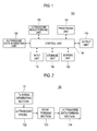
- FIG. 1 is a block diagram showing an illustrative embodiment of an ultrasound system.
- the ultrasound system 100 may include an input unit 110 for allowing a user to input instructions.
- the instructions may include selection instructions for selecting a target object for diagnosis among a plurality of objects and a specific examination location for the selected target object.
- the instructions may further include output instructions for requesting an output of the ultrasound image and showing/hiding image indicators on a screen.
- the target object, examination location and image indicators will be described in detail later.
- the input unit 110 may include at least one of a control panel, a mouse, a keyboard, a trackball, a touch screen, etc.
- the ultrasound system 100 may further include an ultrasound data acquisition unit 120.
- the ultrasound data acquisition unit 120 may transmit and receive ultrasound signals to and from the target object to thereby acquire ultrasound data corresponding to a plurality of frames.
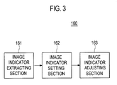
- the ultrasound data acquisition unit 120 may include a transmit (Tx) signal generating section 121, which may be configured to generate a plurality of Tx signals.
- the ultrasound data acquisition unit 120 may further include an ultrasound probe 122 coupled to the Tx signal generating section 121.
- the ultrasound probe 122 may transmit the ultrasound signals to the target object in response to the Tx signals.
- the ultrasound probe 122 may be further configured to receive echo signals reflected from the target object to thereby form electrical receive signals.
- the ultrasound probe 122 may contain an array transducer consisting of a plurality of transducer elements.
- the ultrasound probe 122 may include a convex probe, a linear probe, a 3-dimensional probe, an insertion probe etc., although it is not limited thereto.
- the insertion probe may include a transvaginal probe and a transrectal probe.
- the ultrasound data acquisition unit 120 may further include a beam forming section 123.
- the beam forming section 123 may apply delays to the electrical receive signals in consideration of positions of the transducer elements and focal points.
- the beam forming section 123 may further sum the delayed receive signals to thereby output a plurality of receive-focused beams.
- the ultrasound data acquisition unit 120 may further include an ultrasound data forming section 124, which may form the ultrasound data corresponding to the plurality of frames based on the receive-focused beams.
- the ultrasound data forming section 124 may be operable to perform signal processing upon the receive-focused beams such as gain adjustment, filtering and the like.
- the ultrasound system 100 may further include an ultrasound image forming unit 130 connected to the ultrasound data acquisition unit 120 to receive the ultrasound data.
- the ultrasound image forming unit 130 may form an ultrasound image of the target object by using the ultrasound data.
- the ultrasound image may include a brightness-mode image formed by using reflection coefficients of echo signals reflected from the target object, a Doppler-mode image showing spectral Doppler representative of velocities of a moving object by using the Doppler Effect, a color-mode image showing velocities of moving objects by using predetermined colors mapped to the respective velocities, an elastic image visualizing mechanical characteristics of tissues based on strain representing deformation of tissues due to the application of the compression and the like.
- the ultrasound system 100 may further include a storage unit 140, which may store predetermined image indicators corresponding to a plurality of objects and examination locations for each object.
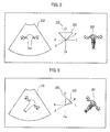
- the image indicators may include target organ markers indicative of the objects such as a heart, liver, stomach, uterus, anus and the like. It may also include body axis markers indicative of anatomical orientation of the examination location for each object such as cranial Cr, caudal Ca, anterior A, posterior P, right R and left L on a 2-dimensional or 3-dimensional coordinate system.
- the image indicators may further include an ultrasound beam direction marker indicative of a transmission direction of an ultrasound beam transmitted from the ultrasound probe 122 for each examination location.
- the storage unit 140 may store a mapping table associating the objects and examination locations for each object with the image indicators including the target organ markers, body axis markers and ultrasound beam direction markers, as shown in FIG. 4 .
- the target organ markers may be 3-dimensionally or 2-dimensionally represented.
- the body axis markers may be represented on a 3-dimensional Cartesian coordinate system.
- the ultrasound beam direction marker may be 2-dimensionally or 3-dimensionally represented according to the type of the ultrasound probe 122. For example, when the ultrasound probe 122 is a 1-dimensional array probe, the ultrasound beam direction marker may be 2-dimensionally represented. Also, when the ultrasound probe 122 is a 2-dimensional array probe or a 3-dimensional mechanical probe, the ultrasound beam direction marker may be 3-dimensionally represented.
- the ultrasound system 100 may further include a sensing unit 150, which may sense a position of the ultrasound probe 122 to thereby form 3-dimensional position information of the ultrasound probe 122.
- the sensing unit 150 may be mounted on a predetermined position of the ultrasound probe 122. Thus, when the ultrasound probe 122 is located in a specific examination location, the sensing unit 150 may sense the 3-dimensional position of the ultrasound probe 122 to form the position information. Any type of sensors capable of sensing a 3-dimensional position of the ultrasound probe 122 may be employed as the sensing unit 150.
- the sensing unit 150 may include at least one of an angular velocity sensor, magnetic sensor, accelerometer sensor, gravity sensor, Gyro sensor and the like.
- the ultrasound system 100 may further include a processing unit 160.
- the processing unit 160 may access the storage unit 140 to provide the image indicators corresponding to an object and an examination location selected in response to the instruction inputted by the user.
- the processing unit 160 may further 3-dimensionally rotate the provided image indicators based on the position information of the ultrasound probe 122, which is formed by the sensing unit 150.
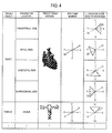
- FIG. 3 is a block diagram showing an illustrative embodiment of the processing unit 160.
- the processing unit 160 may include an image indicator extracting section 161.
- the image indicator extracting section 161 may access the storage unit 140 in response to the selection instruction inputted by the user to extract the image indicators (i.e., target organ marker, body axis marker and ultrasound beam direction marker). For example, if the selection instructions for selecting the uterus as a target object and the vagina as an examination location are inputted through the input unit 110, then the image indicator extracting section 161 may access the storage unit 140 to extract the corresponding image indicators including the target organ marker, body axis marker and ultrasound beam from the mapping table.
- the image indicators i.e., target organ marker, body axis marker and ultrasound beam direction marker
- the image indicator extracting section 161 may access the storage unit 140 to extract the image indicators including the target organ marker, body axis marker and ultrasound beam corresponding to the heart and the parasternal view.
- the processing unit 160 may further include an image indicator setting section 162.
- the image indicator setting section 160 may perform orientation setting of the extracted image indicators based on the position information of the ultrasound probe 122.
- the image indicators, which are set by the image indicator setting section 160, may be outputted to an output unit 170.
- the output unit 170 may include a display unit (not shown) such as a CRT monitor, LCD display, OLED display and the like to display the ultrasound image. Further, the output unit 170 may include an echo printer (not shown) to print out the ultrasound image and the image indicators.
- the image indicator setting section 162 may arrange the extracted body axis marker 222 and ultrasound beam direction marker 223 based on anatomical characteristics of the target object, and set the ultrasound beam direction marker 223 to be overlaid over the body axis marker 222, as shown in FIG. 5 . Further, the image indicator setting section 162 may position the target organ marker 221 at the right side of the body axis marker 222 and the ultrasound beam direction marker 223 to perform the orientation setting upon the body axis marker 222, the ultrasound beam direction marker 223 and the target organ marker 221 based on the position information.
- the body axis marker is overlaid over the ultrasound beam marker and the target organ marker is positioned at the right side of the body axis marker, the arrangement thereof may not be limited thereto.
- the body axis marker, the ultrasound beam direction marker and the target organ marker may be set to be overlaid or to be separated from each other.
- the image processing unit 160 may further include an image indicator adjusting section 163. If the ultrasound probe 122 is moved along a predetermined guide line, then the position information of the ultrasound probe 122 may be changed.
- the image indicator adjusting section 163 may be configured to adjust the image indicators based on the changed position information. For example, the image indicator adjusting section 163 may rotate the image indicators 3-dimensionally based on the changed position information.
- the image indicator adjusting section 163 may compute a position difference of the ultrasound probe 122 based on the changed position information, and 3-dimensionally rotate the image indicators including the target organ marker 221, the body axis marker 22 and the ultrasound beam direction marker 223 based on the computed position difference, as illustrated in FIG. 6 .
- reference numeral "210" may represent an ultrasound image.
- the image indicator adjusting section 163 may further show or hide the image indicator in response to an instruction for showing/hiding the image indicators on a screen, which may be inputted through the input unit 110.
- the ultrasound system 100 may further include a control unit 180.
- the control unit 180 may control the transmission and reception of the ultrasound signals in the ultrasound data acquisition unit 120 according to an image mode. Further, the control unit 180 may be configured to control entire operations of the elements of the ultrasound system 100.
Landscapes
- Health & Medical Sciences (AREA)
- Life Sciences & Earth Sciences (AREA)
- Engineering & Computer Science (AREA)
- Medical Informatics (AREA)
- Surgery (AREA)
- Pathology (AREA)
- Radiology & Medical Imaging (AREA)
- Biophysics (AREA)
- Biomedical Technology (AREA)
- Heart & Thoracic Surgery (AREA)
- Physics & Mathematics (AREA)
- Molecular Biology (AREA)
- Nuclear Medicine, Radiotherapy & Molecular Imaging (AREA)
- Animal Behavior & Ethology (AREA)
- General Health & Medical Sciences (AREA)
- Public Health (AREA)
- Veterinary Medicine (AREA)
- Computer Graphics (AREA)
- General Engineering & Computer Science (AREA)
- Human Computer Interaction (AREA)
- Ultra Sonic Daignosis Equipment (AREA)
Abstract
Embodiments of providing image indicators together with an ultrasound image are disclosed. A mapping table including a plurality of objects each associated with examination locations, each of the examination locations being associated with one or more image indicators. The image indicators include a target organ marker indicative of each object, a body axis marker indicative of an anatomical orientation of each object, and an ultrasound beam direction marker indicative of a transmission direction of the ultrasound beam. A processing unit accesses the storage unit to provide the image indicators corresponding to a target object and examination location selected in response to selection instructions inputted by a user. The processing unit further 3-dimensionally rotates the image indicators based on position information of an ultrasound probe.
Description
- The present application claims priority from Korean Patent Application No.
10-2009-0006570 filed on January 28, 2009 - The present disclosure generally relates to an ultrasound system, and more particularly to an ultrasound system that can provide image indicators corresponding to a target object.
- An ultrasound system has become an important and popular diagnostic tool since it has a wide range of applications. Specifically, due to its non-invasive and non-destructive nature, the ultrasound system has been extensively used in the medical profession. Modem high-performance ultrasound systems and techniques are commonly used to produce two or three-dimensional diagnostic images of internal features of an object (e.g., human organs).
- Generally, the ultrasound system provides a relatively narrow view angle. This is so that scanning is performed for multiple examination locations of a target object to form ultrasound images corresponding to the respective examination locations. The ultrasound images may be outputted by using an echo printer. The examination is then implemented through the outputted ultrasound images. However, it may be difficult to intuitively recognize which part is scanned or which ultrasound image corresponds to an up, down, left or right ultrasound image of the target object. Thus, the ultrasound images may be outputted together with image indicators (e.g., icons) indicative of corresponding examination parts. The image indicators may be also referred to as body markers. The image indicators may be overlaid on the ultrasound images as texts. For example, if a user selects a text button on a control panel provided by the ultrasound system, then a text input window may be activated on the ultrasound image. The user may manipulate a track ball mounted on the control panel to position a cursor on the text input window for text input. Inputting the text may be performed by using a keyboard, which is also mounted on the control panel. However, inputting the text in such fashion may take a long time and greatly inconvenience the user. Also, since the image indicators are directly selected by the user, the image indicators may be incorrectly set.
- Embodiments for providing image indicators in an ultrasound system are disclosed herein. In one embodiment, by way of non-limiting example, an ultrasound system comprises: an ultrasound probe configured to transmit and receive an ultrasound beam to and from a target object for ultrasound imaging; a sensing unit configured to sense a 3-dimensional position of the ultrasound probe to form position information; a storage unit to store a mapping table associating a plurality of objects and examination locations for each object with predetermined image indicators including a target organ marker indicative of each object, a body axis marker indicative of an anatomical orientation of the examination location for each object, and an ultrasound beam direction marker indicative of a transmission direction of the ultrasound beam; an input unit configured to allow a user to input selection instructions for selecting the target object among the plurality of objects and an examination location for the target object; and a processing unit configured to access the storage unit to provide the image indicators corresponding to the target object and examination location in response to the selection instructions and to 3-dimensionally rotate the image indicators based on the position information of the ultrasound probe.
- In one embodiment, there is provided a method of providing an image indicator in an ultrasound system including an ultrasound probe, comprising: a) storing a mapping table associating a plurality of objects and examination locations for each object with predetermined image indicators in a storage unit, the image indicators including a target organ marker indicative of each object, a body axis marker indicative of an anatomical orientation of the examination location of each object, and an ultrasound beam direction marker indicative of a transmission direction of the ultrasound beam; b) inputting selection instructions for selecting a target object among the plurality of objects and an examination location for the target object; c) accessing the storage unit to provide image indicators corresponding to the selected target object and examination location in response to the inputted instructions; d) sensing a position of the ultrasound probe by using a sensing unit mounted on the ultrasound probe to form position information; and e) 3-dimensionally rotating the image indicators based on the position information.
-
- FIG. 1
- is a block diagram showing an illustrative embodiment of an ultrasound system.
- FIG. 2
- is a block diagram showing an illustrative embodiment of an ultrasound data acquisition unit.
- FIG. 3
- is a block diagram showing an illustrative embodiment of a processing unit.
- FIG. 4
- is an exemplary diagram showing a mapping table associating a plurality of objects and examination locations for each of the objects with image indicators.
- FIG. 5
- is a schematic diagram showing an example of displaying image indictors together with an ultrasound image.
- FIG. 6
- is a schematic diagram showing an example of displaying image indicators together with an ultrasound image, wherein their orientation has been adjusted according to position information of an ultrasound probe.
- A detailed description may be provided with reference to the accompanying drawings. One of ordinary skill in the art may realize that the following description is illustrative only and is not in any way limiting. Other embodiments of the present invention may readily suggest themselves to such skilled persons having the benefit of this disclosure.
-
FIG. 1 is a block diagram showing an illustrative embodiment of an ultrasound system. As shown therein, theultrasound system 100 may include aninput unit 110 for allowing a user to input instructions. The instructions may include selection instructions for selecting a target object for diagnosis among a plurality of objects and a specific examination location for the selected target object. The instructions may further include output instructions for requesting an output of the ultrasound image and showing/hiding image indicators on a screen. The target object, examination location and image indicators will be described in detail later. Theinput unit 110 may include at least one of a control panel, a mouse, a keyboard, a trackball, a touch screen, etc. - The
ultrasound system 100 may further include an ultrasounddata acquisition unit 120. The ultrasounddata acquisition unit 120 may transmit and receive ultrasound signals to and from the target object to thereby acquire ultrasound data corresponding to a plurality of frames. Referring toFIG. 2 , the ultrasounddata acquisition unit 120 may include a transmit (Tx)signal generating section 121, which may be configured to generate a plurality of Tx signals. - The ultrasound
data acquisition unit 120 may further include anultrasound probe 122 coupled to the Txsignal generating section 121. Theultrasound probe 122 may transmit the ultrasound signals to the target object in response to the Tx signals. Theultrasound probe 122 may be further configured to receive echo signals reflected from the target object to thereby form electrical receive signals. Theultrasound probe 122 may contain an array transducer consisting of a plurality of transducer elements. In one embodiment, theultrasound probe 122 may include a convex probe, a linear probe, a 3-dimensional probe, an insertion probe etc., although it is not limited thereto. The insertion probe may include a transvaginal probe and a transrectal probe. - The ultrasound
data acquisition unit 120 may further include abeam forming section 123. Thebeam forming section 123 may apply delays to the electrical receive signals in consideration of positions of the transducer elements and focal points. Thebeam forming section 123 may further sum the delayed receive signals to thereby output a plurality of receive-focused beams. The ultrasounddata acquisition unit 120 may further include an ultrasounddata forming section 124, which may form the ultrasound data corresponding to the plurality of frames based on the receive-focused beams. The ultrasounddata forming section 124 may be operable to perform signal processing upon the receive-focused beams such as gain adjustment, filtering and the like. - The
ultrasound system 100 may further include an ultrasoundimage forming unit 130 connected to the ultrasounddata acquisition unit 120 to receive the ultrasound data. The ultrasoundimage forming unit 130 may form an ultrasound image of the target object by using the ultrasound data. The ultrasound image may include a brightness-mode image formed by using reflection coefficients of echo signals reflected from the target object, a Doppler-mode image showing spectral Doppler representative of velocities of a moving object by using the Doppler Effect, a color-mode image showing velocities of moving objects by using predetermined colors mapped to the respective velocities, an elastic image visualizing mechanical characteristics of tissues based on strain representing deformation of tissues due to the application of the compression and the like. - The
ultrasound system 100 may further include astorage unit 140, which may store predetermined image indicators corresponding to a plurality of objects and examination locations for each object. In one embodiment, the image indicators may include target organ markers indicative of the objects such as a heart, liver, stomach, uterus, anus and the like. It may also include body axis markers indicative of anatomical orientation of the examination location for each object such as cranial Cr, caudal Ca, anterior A, posterior P, right R and left L on a 2-dimensional or 3-dimensional coordinate system. The image indicators may further include an ultrasound beam direction marker indicative of a transmission direction of an ultrasound beam transmitted from theultrasound probe 122 for each examination location. In one embodiment, thestorage unit 140 may store a mapping table associating the objects and examination locations for each object with the image indicators including the target organ markers, body axis markers and ultrasound beam direction markers, as shown inFIG. 4 . - In one embodiment, the target organ markers may be 3-dimensionally or 2-dimensionally represented. Also, the body axis markers may be represented on a 3-dimensional Cartesian coordinate system. Further, the ultrasound beam direction marker may be 2-dimensionally or 3-dimensionally represented according to the type of the
ultrasound probe 122. For example, when theultrasound probe 122 is a 1-dimensional array probe, the ultrasound beam direction marker may be 2-dimensionally represented. Also, when theultrasound probe 122 is a 2-dimensional array probe or a 3-dimensional mechanical probe, the ultrasound beam direction marker may be 3-dimensionally represented. - The
ultrasound system 100 may further include asensing unit 150, which may sense a position of theultrasound probe 122 to thereby form 3-dimensional position information of theultrasound probe 122. Thesensing unit 150 may be mounted on a predetermined position of theultrasound probe 122. Thus, when theultrasound probe 122 is located in a specific examination location, thesensing unit 150 may sense the 3-dimensional position of theultrasound probe 122 to form the position information. Any type of sensors capable of sensing a 3-dimensional position of theultrasound probe 122 may be employed as thesensing unit 150. For example, thesensing unit 150 may include at least one of an angular velocity sensor, magnetic sensor, accelerometer sensor, gravity sensor, Gyro sensor and the like. - The
ultrasound system 100 may further include aprocessing unit 160. Theprocessing unit 160 may access thestorage unit 140 to provide the image indicators corresponding to an object and an examination location selected in response to the instruction inputted by the user. Theprocessing unit 160 may further 3-dimensionally rotate the provided image indicators based on the position information of theultrasound probe 122, which is formed by thesensing unit 150. -
FIG. 3 is a block diagram showing an illustrative embodiment of theprocessing unit 160. Referring toFIG. 3 , theprocessing unit 160 may include an imageindicator extracting section 161. The imageindicator extracting section 161 may access thestorage unit 140 in response to the selection instruction inputted by the user to extract the image indicators (i.e., target organ marker, body axis marker and ultrasound beam direction marker). For example, if the selection instructions for selecting the uterus as a target object and the vagina as an examination location are inputted through theinput unit 110, then the imageindicator extracting section 161 may access thestorage unit 140 to extract the corresponding image indicators including the target organ marker, body axis marker and ultrasound beam from the mapping table. Also, the selection instructions for selecting the heart as the target object and the parasternal view as the examination location are inputted through theinput unit 110, the imageindicator extracting section 161 may access thestorage unit 140 to extract the image indicators including the target organ marker, body axis marker and ultrasound beam corresponding to the heart and the parasternal view. - The
processing unit 160 may further include an imageindicator setting section 162. The imageindicator setting section 160 may perform orientation setting of the extracted image indicators based on the position information of theultrasound probe 122. The image indicators, which are set by the imageindicator setting section 160, may be outputted to anoutput unit 170. Theoutput unit 170 may include a display unit (not shown) such as a CRT monitor, LCD display, OLED display and the like to display the ultrasound image. Further, theoutput unit 170 may include an echo printer (not shown) to print out the ultrasound image and the image indicators. For example, the imageindicator setting section 162 may arrange the extractedbody axis marker 222 and ultrasoundbeam direction marker 223 based on anatomical characteristics of the target object, and set the ultrasoundbeam direction marker 223 to be overlaid over thebody axis marker 222, as shown inFIG. 5 . Further, the imageindicator setting section 162 may position thetarget organ marker 221 at the right side of thebody axis marker 222 and the ultrasoundbeam direction marker 223 to perform the orientation setting upon thebody axis marker 222, the ultrasoundbeam direction marker 223 and thetarget organ marker 221 based on the position information. - Although the above embodiment has been described that the body axis marker is overlaid over the ultrasound beam marker and the target organ marker is positioned at the right side of the body axis marker, the arrangement thereof may not be limited thereto. The body axis marker, the ultrasound beam direction marker and the target organ marker may be set to be overlaid or to be separated from each other.
- The
image processing unit 160 may further include an imageindicator adjusting section 163. If theultrasound probe 122 is moved along a predetermined guide line, then the position information of theultrasound probe 122 may be changed. The imageindicator adjusting section 163 may be configured to adjust the image indicators based on the changed position information. For example, the imageindicator adjusting section 163 may rotate the image indicators 3-dimensionally based on the changed position information. The imageindicator adjusting section 163 may compute a position difference of theultrasound probe 122 based on the changed position information, and 3-dimensionally rotate the image indicators including thetarget organ marker 221, the body axis marker 22 and the ultrasoundbeam direction marker 223 based on the computed position difference, as illustrated inFIG. 6 . InFIGS. 5 and 6 , reference numeral "210" may represent an ultrasound image. The imageindicator adjusting section 163 may further show or hide the image indicator in response to an instruction for showing/hiding the image indicators on a screen, which may be inputted through theinput unit 110. - Referring back to
FIG. 1 , theultrasound system 100 may further include acontrol unit 180. Thecontrol unit 180 may control the transmission and reception of the ultrasound signals in the ultrasounddata acquisition unit 120 according to an image mode. Further, thecontrol unit 180 may be configured to control entire operations of the elements of theultrasound system 100. - While the present invention is described by some preferred embodiments, it will be appreciated by those skilled in the art that many modifications and changes can be made without departing from the spirit and scope of the appended claims.
Claims (15)
- An ultrasound system, comprising:an ultrasound probe configured to transmit and receive an ultrasound beam to and from a target object for ultrasound imaging;a sensing unit configured to sense a 3-dimensional position of the ultrasound probe to form position information;a storage unit configured to store a mapping table including a plurality of objects each associated with examination locations, each of the examination locations being associated with one or more image indicators, the one or more image indicators including a target organ marker indicative of the respective object, a body axis marker indicative of an anatomical orientation determined according to the respective examination location, and an ultrasound beam direction marker indicative of a transmission direction of the ultrasound beam determined according to the respective examination location;an input unit configured to allow a user to input one or more selection instructions for selecting a target object among the plurality of objects and one of the examination locations for the target object; anda processing unit configured to access the storage unit to provide the image indicators corresponding to the target object and the one examination location in response to the selection instructions and to rotate the image indicators 3-dimensionally based on the position information of the ultrasound probe.
- The ultrasound system of Claim 1, wherein the target organ marker is represented in a 2-dimensional or 3-dimensional marker, and the ultrasound beam direction marker is 2-dimensionally or 3-dimensionally represented according to a type of the ultrasound probe.
- The ultrasound system of Claim 1, wherein the sensing unit is selected from the group consisting of an angular velocity sensor, magnetic sensor, accelerometer sensor, gravity sensor, Gyro sensor and combinations thereof.
- The ultrasound system of Claim 1, wherein the processing unit includes:an image indicator extracting section configured to access the storage unit to extract the target organ marker, the body axis marker and the ultrasound beam direction marker corresponding to the target object and the examination location selected in response to the instructions;an image indicator setting section configured to perform orientation setting upon the extracted target organ marker, body axis marker and ultrasound beam direction marker based on the position information; andan image indicator adjusting section configured to rotate the extracted target organ marker, body axis marker and ultrasound beam direction marker 3-dimensionally based on position information changed due to a movement of the ultrasound probe.
- The ultrasound system of Claim 4, wherein the image indicator setting section is configured to arrange the extracted target organ marker, body axis marker and ultrasound beam direction marker based on anatomical characteristics of the target object.
- The ultrasound system of Claim 1, wherein the input unit is configured to allow a user to input instructions for showing/hiding the image indicators, and the processing unit is configured to show/hide the image indicator in response to the instructions for showing/hiding the image indicator.
- The ultrasound system of Claim 1, further comprising an output unit to output the image indicator.
- A method of providing an image indicator in an ultrasound system including an ultrasound probe, comprising:a) storing a mapping table including a plurality of objects each associated with examination locations, each of the examination locations being associated with one or more image indicators, the one or more image indicators including a target organ marker indicative of the respective object, a body axis marker indicative of an anatomical orientation determined according to the respective examination location, and an ultrasound beam direction marker indicative of a transmission direction of the ultrasound beam determined according to the respective examination location;b) inputting one or more selection instructions for selecting a target object among the plurality of objects and one of the examination locations for the target object;c) accessing the storage unit to provide image indicators corresponding to the selected target object and examination location in response to the inputted instructions;d) sensing a position of the ultrasound probe by using a sensing unit mounted on the ultrasound probe to form position information; ande) 3-dimensionally rotating the image indicators based on the position information.
- The method of Claim 10, wherein the target organ marker is represented in a 2-dimensional or 3-dimensional marker, and the ultrasound beam direction marker is 2-dimensionally or 3-dimensionally represented according to a type of the ultrasound probe.
- The method of Claim 8, wherein the sensing unit is selected from the group consisting of an angular velocity sensor, magnetic sensor, accelerometer sensor, gravity sensor, Gyro sensor and combinations thereof.
- The method of Claim 8, wherein step c) includes:accessing the storage unit to extract the target organ marker, the body axis marker and the ultrasound beam direction marker corresponding to the target object and the examination location selected in response to the instructions;andperforming orientation setting upon the extracted target organ marker, body axis marker and ultrasound beam direction marker based on the position information.
- The method of Claim 11, wherein step e) includes 3-dimensionally rotating the extracted target organ marker, body axis marker and ultrasound beam direction marker based on position information changed due to a movement of the ultrasound probe.
- The method of Claim 12, wherein step c) further includes arranging the extracted target organ marker, body axis marker and ultrasound beam direction marker based on anatomical characteristics of the target object.
- The method of Claim 8, further comprising inputting instructions for showing/hiding the image indicators and showing/hiding the image indicator in response to the instructions for showing/hiding the image indicator.
- The method of Claim 8, further comprising outputting the image indicators.
Applications Claiming Priority (1)
| Application Number | Priority Date | Filing Date | Title |
|---|---|---|---|
| KR1020090006570A KR101182880B1 (en) | 2009-01-28 | 2009-01-28 | Ultrasound system and method for providing image indicator |
Publications (1)
| Publication Number | Publication Date |
|---|---|
| EP2213240A1 true EP2213240A1 (en) | 2010-08-04 |
Family
ID=42125154
Family Applications (1)
| Application Number | Title | Priority Date | Filing Date |
|---|---|---|---|
| EP20100150925 Ceased EP2213240A1 (en) | 2009-01-28 | 2010-01-18 | Image indicator provision in an ultrasound system |
Country Status (4)
| Country | Link |
|---|---|
| US (1) | US9211105B2 (en) |
| EP (1) | EP2213240A1 (en) |
| JP (1) | JP2010172701A (en) |
| KR (1) | KR101182880B1 (en) |
Cited By (2)
| Publication number | Priority date | Publication date | Assignee | Title |
|---|---|---|---|---|
| EP2644100A1 (en) * | 2012-03-27 | 2013-10-02 | Samsung Medison Co., Ltd. | Ultrasound diagnosis apparatus and operating method thereof |
| WO2015099835A1 (en) * | 2013-12-27 | 2015-07-02 | General Electric Company | System and method for displaying ultrasound images |
Families Citing this family (24)
| Publication number | Priority date | Publication date | Assignee | Title |
|---|---|---|---|---|
| US8961511B2 (en) | 2006-02-07 | 2015-02-24 | Viveve, Inc. | Vaginal remodeling device and methods |
| PL2477695T3 (en) | 2009-09-18 | 2016-03-31 | Viveve Inc | Vaginal remodeling device |
| WO2012063420A1 (en) * | 2010-11-12 | 2012-05-18 | パナソニック株式会社 | Ultrasound diagnostic apparatus and ultrasound diagnostic system |
| EP2491865A1 (en) | 2011-02-24 | 2012-08-29 | Samsung Medison Co., Ltd. | Ultrasound system for providing image indicator |
| KR101398468B1 (en) * | 2011-02-24 | 2014-05-27 | 삼성메디슨 주식회사 | Ultrasound system for providing image indicator |
| US8672490B2 (en) | 2011-11-30 | 2014-03-18 | Izi Medical Products | High reflectivity retro-reflective marker |
| US8661573B2 (en) | 2012-02-29 | 2014-03-04 | Izi Medical Products | Protective cover for medical device having adhesive mechanism |
| CN105919666A (en) * | 2012-03-16 | 2016-09-07 | 女康乐公司 | Therapy equipment for repairing female vaginal tissue |
| JP2014161444A (en) * | 2013-02-22 | 2014-09-08 | Toshiba Corp | Ultrasound diagnostic device, medical image processor and control program |
| KR102143381B1 (en) * | 2013-05-30 | 2020-08-11 | 삼성메디슨 주식회사 | Ultrasonic image processing apparatus and method |
| KR101611449B1 (en) * | 2014-02-28 | 2016-04-11 | 삼성메디슨 주식회사 | Method for Controlling Medical Imaging Apparatus Having Probe and Medical Imaging Apparatus Thereof |
| KR20160012590A (en) * | 2014-07-24 | 2016-02-03 | 삼성메디슨 주식회사 | Ultrasound imaging apparatus and controlling method thereof |
| KR102388132B1 (en) * | 2014-12-15 | 2022-04-19 | 삼성메디슨 주식회사 | Method, apparatus and system for generating a body marker which indicates an object |
| WO2016192114A1 (en) * | 2015-06-05 | 2016-12-08 | 深圳迈瑞生物医疗电子股份有限公司 | Ultrasonic fluid imaging method and ultrasonic fluid imaging system |
| KR102531117B1 (en) * | 2015-10-07 | 2023-05-10 | 삼성메디슨 주식회사 | Method and apparatus for displaying an image which indicates an object |
| KR102545008B1 (en) * | 2015-10-26 | 2023-06-20 | 삼성메디슨 주식회사 | Ultrasound imaging apparatus and control method for the same |
| KR20180066781A (en) | 2016-12-09 | 2018-06-19 | 삼성전자주식회사 | Method and apparatus for displaying medical image |
| US11511110B2 (en) | 2018-06-27 | 2022-11-29 | Viveve, Inc. | Methods for treating urinary stress incontinence |
| EP3530193A1 (en) | 2018-02-26 | 2019-08-28 | Koninklijke Philips N.V. | Providing a three dimensional ultrasound image |
| US11382601B2 (en) * | 2018-03-01 | 2022-07-12 | Fujifilm Sonosite, Inc. | Method and apparatus for annotating ultrasound examinations |
| CN109567861B (en) * | 2018-10-25 | 2022-06-07 | 中国医学科学院北京协和医院 | Ultrasound imaging method and related apparatus |
| KR102704209B1 (en) * | 2019-01-16 | 2024-09-09 | 삼성메디슨 주식회사 | Ultrasound image apparatus and method for controlling thereof |
| US11974881B2 (en) * | 2020-08-26 | 2024-05-07 | GE Precision Healthcare LLC | Method and system for providing an anatomic orientation indicator with a patient-specific model of an anatomical structure of interest extracted from a three-dimensional ultrasound volume |
| WO2023287705A1 (en) * | 2021-07-12 | 2023-01-19 | Bfly Operations, Inc. | Methods and apparatuses for collection of ultrasound data |
Citations (5)
| Publication number | Priority date | Publication date | Assignee | Title |
|---|---|---|---|---|
| US5211167A (en) * | 1991-02-28 | 1993-05-18 | Olympus Optical Co., Ltd. | Ultrasonic diagnosing apparatus |
| US6500118B1 (en) | 1998-10-23 | 2002-12-31 | Kabushiki Kaisha Toshiba | Three-dimensional ultrasonic diagnostic apparatus |
| US20030065265A1 (en) | 2000-03-02 | 2003-04-03 | Acuson Corporation | Medical diagnostic ultrasound system and method for scanning plane orientation |
| EP1523940A1 (en) | 2003-10-14 | 2005-04-20 | Aloka Co., Ltd. | Ultrasound diagnosis apparatus |
| US20050203417A1 (en) * | 2002-09-24 | 2005-09-15 | Olympus Corporation | Ultrasonic diagnosis apparatus |
Family Cites Families (31)
| Publication number | Priority date | Publication date | Assignee | Title |
|---|---|---|---|---|
| JPS57130259U (en) | 1981-02-06 | 1982-08-13 | ||
| JPS6066735A (en) | 1983-09-22 | 1985-04-16 | 株式会社島津製作所 | Diagnosis site display method for ultrasound diagnostic equipment |
| JPS6072541A (en) | 1983-09-29 | 1985-04-24 | 株式会社島津製作所 | Diagnostic region display method of ultrasonic diagnostic apparatus |
| JPH0515531A (en) | 1991-07-15 | 1993-01-26 | Toshiba Corp | Ultrasonic diagnostic equipment |
| JP3263131B2 (en) | 1992-07-08 | 2002-03-04 | 株式会社東芝 | Ultrasound diagnostic equipment |
| JP2848586B2 (en) | 1994-10-03 | 1999-01-20 | オリンパス光学工業株式会社 | Ultrasound diagnostic equipment |
| US5776050A (en) | 1995-07-24 | 1998-07-07 | Medical Media Systems | Anatomical visualization system |
| JP3723299B2 (en) | 1996-11-13 | 2005-12-07 | 株式会社日立メディコ | Ultrasonic diagnostic equipment |
| JPH1147133A (en) | 1997-08-07 | 1999-02-23 | Nippon Telegr & Teleph Corp <Ntt> | Ultrasound diagnostic equipment |
| JP4350214B2 (en) | 1999-07-06 | 2009-10-21 | 株式会社東芝 | Ultrasonic diagnostic equipment |
| US6290649B1 (en) | 1999-12-21 | 2001-09-18 | General Electric Company | Ultrasound position sensing probe |
| US6755788B2 (en) * | 2000-08-17 | 2004-06-29 | Koninklijke Philips Electronics N. V. | Image orientation display for a three dimensional ultrasonic imaging system |
| US6517491B1 (en) | 2000-10-31 | 2003-02-11 | Koninklijke Philips Electronics N.V | Transducer with spatial sensor |
| US6436040B1 (en) | 2000-11-09 | 2002-08-20 | Koninklijke Philips Electronics N.V. | Intuitive user interface and control circuitry including linear distance measurement and user localization in a portable ultrasound diagnostic device |
| US7030861B1 (en) | 2001-02-10 | 2006-04-18 | Wayne Carl Westerman | System and method for packing multi-touch gestures onto a hand |
| JP2003180696A (en) | 2001-12-17 | 2003-07-02 | Olympus Optical Co Ltd | Ultrasonic diagnostic equipment |
| JP2003260056A (en) | 2002-03-08 | 2003-09-16 | Toshiba Corp | Ultrasound diagnostic equipment |
| US6980419B2 (en) | 2003-03-12 | 2005-12-27 | Zonare Medical Systems, Inc. | Portable ultrasound unit and docking station |
| JP4343592B2 (en) | 2003-06-16 | 2009-10-14 | オリンパス株式会社 | Ultrasonic diagnostic equipment |
| JP2005040301A (en) | 2003-07-28 | 2005-02-17 | Toshiba Corp | Ultrasonic diagnostic apparatus and diagnostic parameter setting method thereof |
| US7398116B2 (en) * | 2003-08-11 | 2008-07-08 | Veran Medical Technologies, Inc. | Methods, apparatuses, and systems useful in conducting image guided interventions |
| JP4681857B2 (en) | 2004-11-25 | 2011-05-11 | オリンパス株式会社 | Ultrasonic diagnostic equipment |
| US7918793B2 (en) * | 2005-10-28 | 2011-04-05 | Biosense Webster, Inc. | Synchronization of ultrasound imaging data with electrical mapping |
| JP5209213B2 (en) | 2006-01-10 | 2013-06-12 | 株式会社東芝 | Ultrasonic diagnostic apparatus and ultrasonic image generation program |
| JP2007202829A (en) | 2006-02-02 | 2007-08-16 | Hitachi Medical Corp | Ultrasonic diagnostic system |
| US20070255137A1 (en) * | 2006-05-01 | 2007-11-01 | Siemens Medical Solutions Usa, Inc. | Extended volume ultrasound data display and measurement |
| JP2007301030A (en) | 2006-05-09 | 2007-11-22 | Toshiba Corp | Ultrasonic diagnostic equipment |
| KR100875620B1 (en) | 2006-11-09 | 2008-12-26 | 주식회사 메디슨 | Ultrasound Imaging Systems and Methods |
| JP5226244B2 (en) | 2007-05-07 | 2013-07-03 | オリンパスメディカルシステムズ株式会社 | Medical guide system |
| JP2008301969A (en) | 2007-06-06 | 2008-12-18 | Olympus Medical Systems Corp | Ultrasonic diagnostic equipment |
| WO2009051847A1 (en) * | 2007-10-19 | 2009-04-23 | Calin Caluser | Three dimensional mapping display system for diagnostic ultrasound machines and method |
-
2009
- 2009-01-28 KR KR1020090006570A patent/KR101182880B1/en active Active
-
2010
- 2010-01-18 EP EP20100150925 patent/EP2213240A1/en not_active Ceased
- 2010-01-25 US US12/693,347 patent/US9211105B2/en active Active
- 2010-01-27 JP JP2010015396A patent/JP2010172701A/en active Pending
Patent Citations (5)
| Publication number | Priority date | Publication date | Assignee | Title |
|---|---|---|---|---|
| US5211167A (en) * | 1991-02-28 | 1993-05-18 | Olympus Optical Co., Ltd. | Ultrasonic diagnosing apparatus |
| US6500118B1 (en) | 1998-10-23 | 2002-12-31 | Kabushiki Kaisha Toshiba | Three-dimensional ultrasonic diagnostic apparatus |
| US20030065265A1 (en) | 2000-03-02 | 2003-04-03 | Acuson Corporation | Medical diagnostic ultrasound system and method for scanning plane orientation |
| US20050203417A1 (en) * | 2002-09-24 | 2005-09-15 | Olympus Corporation | Ultrasonic diagnosis apparatus |
| EP1523940A1 (en) | 2003-10-14 | 2005-04-20 | Aloka Co., Ltd. | Ultrasound diagnosis apparatus |
Cited By (2)
| Publication number | Priority date | Publication date | Assignee | Title |
|---|---|---|---|---|
| EP2644100A1 (en) * | 2012-03-27 | 2013-10-02 | Samsung Medison Co., Ltd. | Ultrasound diagnosis apparatus and operating method thereof |
| WO2015099835A1 (en) * | 2013-12-27 | 2015-07-02 | General Electric Company | System and method for displaying ultrasound images |
Also Published As
| Publication number | Publication date |
|---|---|
| KR20100087521A (en) | 2010-08-05 |
| JP2010172701A (en) | 2010-08-12 |
| US9211105B2 (en) | 2015-12-15 |
| KR101182880B1 (en) | 2012-09-13 |
| US20100191114A1 (en) | 2010-07-29 |
Similar Documents
| Publication | Publication Date | Title |
|---|---|---|
| US9211105B2 (en) | Image indicator provision in an ultrasound system | |
| JP5702922B2 (en) | An ultrasound system for visualizing an ultrasound probe on an object | |
| US10617384B2 (en) | M-mode ultrasound imaging of arbitrary paths | |
| CN107072635B (en) | Quality metric for multi-hop echocardiography acquisition for intermediate user feedback | |
| US8469890B2 (en) | System and method for compensating for motion when displaying ultrasound motion tracking information | |
| US9420996B2 (en) | Methods and systems for display of shear-wave elastography and strain elastography images | |
| US9386964B2 (en) | 3D view of 2D ultrasound images | |
| US20100249589A1 (en) | System and method for functional ultrasound imaging | |
| US20030065265A1 (en) | Medical diagnostic ultrasound system and method for scanning plane orientation | |
| EP2491865A1 (en) | Ultrasound system for providing image indicator | |
| JP4847334B2 (en) | Ultrasonic imaging apparatus and projection image generation method | |
| US20100249591A1 (en) | System and method for displaying ultrasound motion tracking information | |
| US20100195878A1 (en) | Systems and methods for labeling 3-d volume images on a 2-d display of an ultrasonic imaging system | |
| KR20080053057A (en) | Ultrasound Imaging System and Method for Forming and Displaying Mixed Image of Ultrasound Image and External Medical Image | |
| CN111629671A (en) | Ultrasonic imaging apparatus and method of controlling ultrasonic imaging apparatus | |
| JP2000201925A (en) | 3D ultrasonic diagnostic equipment | |
| WO2016120831A2 (en) | Measurement tools with plane projection in rendered volume imaging | |
| US20100185088A1 (en) | Method and system for generating m-mode images from ultrasonic data | |
| JP3793126B2 (en) | Ultrasonic diagnostic equipment | |
| CN108135570A (en) | Ultrasonic imaging device and control method for the ultrasonic imaging device | |
| CN106983521A (en) | Supersonic imaging apparatus | |
| JP2010068956A (en) | Ultrasonic diagnostic apparatus and ultrasonic diagnostic support program | |
| US20200405264A1 (en) | Region of interest positioning for longitudinal montioring in quantitative ultrasound | |
| US20160066887A1 (en) | Image indicator provision in ultrasound system | |
| KR102695456B1 (en) | Ultrasound diagnostic apparatus for displaying shear wave data of the object and method for operating the same |
Legal Events
| Date | Code | Title | Description |
|---|---|---|---|
| PUAI | Public reference made under article 153(3) epc to a published international application that has entered the european phase |
Free format text: ORIGINAL CODE: 0009012 |
|
| AK | Designated contracting states |
Kind code of ref document: A1 Designated state(s): AT BE BG CH CY CZ DE DK EE ES FI FR GB GR HR HU IE IS IT LI LT LU LV MC MK MT NL NO PL PT RO SE SI SK SM TR |
|
| AX | Request for extension of the european patent |
Extension state: AL BA RS |
|
| 17P | Request for examination filed |
Effective date: 20110202 |
|
| 17Q | First examination report despatched |
Effective date: 20120705 |
|
| STAA | Information on the status of an ep patent application or granted ep patent |
Free format text: STATUS: THE APPLICATION HAS BEEN REFUSED |
|
| 18R | Application refused |
Effective date: 20160315 |