EP2213238A1 - Imaging device - Google Patents
Imaging device Download PDFInfo
- Publication number
- EP2213238A1 EP2213238A1 EP08839456A EP08839456A EP2213238A1 EP 2213238 A1 EP2213238 A1 EP 2213238A1 EP 08839456 A EP08839456 A EP 08839456A EP 08839456 A EP08839456 A EP 08839456A EP 2213238 A1 EP2213238 A1 EP 2213238A1
- Authority
- EP
- European Patent Office
- Prior art keywords
- plate
- shaped portion
- cover
- fixing
- signal cable
- Prior art date
- Legal status (The legal status is an assumption and is not a legal conclusion. Google has not performed a legal analysis and makes no representation as to the accuracy of the status listed.)
- Granted
Links
Images









Classifications
-
- A—HUMAN NECESSITIES
- A61—MEDICAL OR VETERINARY SCIENCE; HYGIENE
- A61B—DIAGNOSIS; SURGERY; IDENTIFICATION
- A61B6/00—Apparatus or devices for radiation diagnosis; Apparatus or devices for radiation diagnosis combined with radiation therapy equipment
- A61B6/50—Apparatus or devices for radiation diagnosis; Apparatus or devices for radiation diagnosis combined with radiation therapy equipment specially adapted for specific body parts; specially adapted for specific clinical applications
- A61B6/51—Apparatus or devices for radiation diagnosis; Apparatus or devices for radiation diagnosis combined with radiation therapy equipment specially adapted for specific body parts; specially adapted for specific clinical applications for dentistry
- A61B6/512—Intraoral means
-
- A—HUMAN NECESSITIES
- A61—MEDICAL OR VETERINARY SCIENCE; HYGIENE
- A61B—DIAGNOSIS; SURGERY; IDENTIFICATION
- A61B6/00—Apparatus or devices for radiation diagnosis; Apparatus or devices for radiation diagnosis combined with radiation therapy equipment
- A61B6/42—Arrangements for detecting radiation specially adapted for radiation diagnosis
- A61B6/4208—Arrangements for detecting radiation specially adapted for radiation diagnosis characterised by using a particular type of detector
- A61B6/4233—Arrangements for detecting radiation specially adapted for radiation diagnosis characterised by using a particular type of detector using matrix detectors
-
- H—ELECTRICITY
- H04—ELECTRIC COMMUNICATION TECHNIQUE
- H04N—PICTORIAL COMMUNICATION, e.g. TELEVISION
- H04N23/00—Cameras or camera modules comprising electronic image sensors; Control thereof
- H04N23/30—Cameras or camera modules comprising electronic image sensors; Control thereof for generating image signals from X-rays
-
- H—ELECTRICITY
- H04—ELECTRIC COMMUNICATION TECHNIQUE
- H04N—PICTORIAL COMMUNICATION, e.g. TELEVISION
- H04N23/00—Cameras or camera modules comprising electronic image sensors; Control thereof
- H04N23/50—Constructional details
-
- H—ELECTRICITY
- H10—SEMICONDUCTOR DEVICES; ELECTRIC SOLID-STATE DEVICES NOT OTHERWISE PROVIDED FOR
- H10F—INORGANIC SEMICONDUCTOR DEVICES SENSITIVE TO INFRARED RADIATION, LIGHT, ELECTROMAGNETIC RADIATION OF SHORTER WAVELENGTH OR CORPUSCULAR RADIATION
- H10F77/00—Constructional details of devices covered by this subclass
- H10F77/50—Encapsulations or containers
-
- H—ELECTRICITY
- H04—ELECTRIC COMMUNICATION TECHNIQUE
- H04N—PICTORIAL COMMUNICATION, e.g. TELEVISION
- H04N23/00—Cameras or camera modules comprising electronic image sensors; Control thereof
- H04N23/50—Constructional details
- H04N23/555—Constructional details for picking-up images in sites, inaccessible due to their dimensions or hazardous conditions, e.g. endoscopes or borescopes
-
- H—ELECTRICITY
- H10—SEMICONDUCTOR DEVICES; ELECTRIC SOLID-STATE DEVICES NOT OTHERWISE PROVIDED FOR
- H10F—INORGANIC SEMICONDUCTOR DEVICES SENSITIVE TO INFRARED RADIATION, LIGHT, ELECTROMAGNETIC RADIATION OF SHORTER WAVELENGTH OR CORPUSCULAR RADIATION
- H10F39/00—Integrated devices, or assemblies of multiple devices, comprising at least one element covered by group H10F30/00, e.g. radiation detectors comprising photodiode arrays
- H10F39/80—Constructional details of image sensors
- H10F39/804—Containers or encapsulations
Definitions
- the present invention relates to an imaging device, inserted into an oral cavity, for imaging teeth, etc.
- Patent Documents 1 to 3 disclose imaging devices for photographing teeth, etc., in an oral cavity.
- a signal cable is connected to a circuit board on the rear side of an imaging surface.
- a signal cable extends via a capsule, a bobbin, etc., on the rear side of an imaging surface.
- a signal cable is connected to a circuit board on the rear side of an imaging surface via a cap, a sleeve, etc.
- the signal cable extends from an opposite side of the imaging surface on which to receive imaging light.
- the number of opportunities for which the signal cable comes into contact with the oral cavity is decreased, and as a result, discomfort that a patient feels at the time of photographing the oral cavity can be suppressed.
- the signal cable thus extends from the opposite side of the imaging surface, the discomfort felt by the patient is decreased, and at the same time, the strength for the tension or bending of the signal cable is decreased. Therefore, due to the bending or tension of the signal cable, there is a possibility in such a sensor that a problem occurs to an electrical connection between the signal cable and the sensor.
- an object of the present invention is to improve a connection strength between a package of an imaging device and a signal cable extending from an opposite side of an imaging surface.
- An imaging device includes: a package having a case including a first plate-shaped portion and a second plate-shaped portion facing the first plate-shaped portion, and a cover, arranged on an outer surface of the second plate-shaped portion, for covering an opening formed in the second plate-shaped portion; a photodetecting element having a light incident surface and being contained in the case so that the light incident surface faces the first plate-shaped portion; and a fixing unit, arranged between the second plate-shaped portion and the cover, for fixing to the package a signal cable connected to the photodetecting element extending via the opening from the inside to the outside of the case.
- the signal cable when the signal cable is pulled out from the opposite side of the photodetecting surface, the signal cable is fixed to the package by the fixing unit.
- the signal cable is fixed to the package by the fixing unit, and thus, even when there is bending or tension for the signal cable, it is possible to avoid a situation where a problem occurs to the electrical connection with the signal cable.
- the imaging device of the present invention it is possible to improve a connection strength between a package of an imaging device and a signal cable extending from an opposite side of an imaging surface.
- FIG. 1 shows an appearance of an intraoral sensor 1 according to an embodiment.
- the intraoral sensor 1 is an imaging device, inserted into an oral cavity of a patient, for imaging an X-ray image of teeth, etc., in an oral cavity.
- the intraoral sensor 1 is connected to a signal cable 24 extending from a control device for controlling the intraoral sensor 1.
- the intraoral sensor 1 is provided with a package 2.
- the package 2 includes a first plate-shaped portion 12 and a second plate-shaped portion 16 spaced and facing each other, and a side-wall portion 20 extending between the peripheral edge of the first plate-shaped portion 12 and the peripheral edge of the second plate-shaped portion 16.
- the side-wall portion 20 includes a first side-wall member 14 extending from the peripheral edge of the first plate-shaped portion 12 and a second side-wall member 18 extending from the peripheral edge of the second plate-shaped portion 16.
- an opening 16a (for example, see FIG. 2 , etc.) formed through a case 4 from the outside to the inside is provided.
- the package 2 includes the case 4 and a cover 6.
- the case 4 includes a first case member 8 and a second case member 10.
- the first case member 8 includes the first plate-shaped portion 12 and the first side-wall member 14.
- the second case member 10 includes the second plate-shaped portion 16 and the second side-wall member 18.
- the intraoral sensor 1 includes the cover 6.
- the cover 6 is arranged on the outer surface of the second plate-shaped portion 16.
- the cover 6 covers the opening 16a (for example, see FIG. 2 , etc.).
- the cover 6 includes a hole portion 22, and the hole portion 22 is formed through the cover 6 from the outside to the inside.
- the signal cable 24 extends from the outside to the inside of the cover 6 via the hole portion 22, and extends, via the opening 16a, from the inside of the cover 6 (outside of the case 4) to the inside of the case 4.
- the signal cable 24 is connected to a photodetecting element 34 arranged within the case 4 (for example, see FIG. 2 , etc.).
- the X-ray is incident on the first plate-shaped portion 12, and the signal cable 24 is pulled out from the side of the second plate-shaped portion 16 opposite (on the back surface side of) the first plate-shaped portion 12 on which the X-ray is incident.
- the intraoral sensor 1 includes a fixing unit for fixing the signal cable 24 to the case 4.
- the fixing unit is arranged between the second plate-shaped portion 16 and the cover 6, fixes to the package 2 the signal cable 24 extending, via the opening 16a, from the inside to the outside of the case 4.
- Specific examples of the fixing unit are shown in FIG. 10 to FIG. 15 , and will be described in detail later. It is noted that in FIG. 2 to FIG. 9 , the fixing unit (a fixing member 32a and a fixing member 32b) shown in FIG. 10 is described as an example.
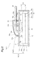
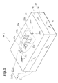
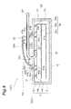
- FIG. 2 , FIG. 4 , FIG. 6 , and FIG. 5 The configuration of the intraoral sensor 1a is shown in FIG. 2 and FIG. 3 , the configuration of the intraoral sensor 1b is shown in FIG. 4 and FIG. 5 , the configuration of the intraoral sensor 1c is shown in FIG. 6 and FIG. 7 , and the configuration of the intraoral sensor 1d is shown in FIG. 8 and FIG. 9 .
- FIG. 8 are diagrams showing cross-sectional structures of the intraoral sensor 1 (the intraoral sensor 1a to the intraoral sensor 1d) along a line 1-1 shown in FIG. 1
- FIG. 3 , FIG. 5 , FIG. 7 , and FIG. 9 are perspective views respectively showing the intraoral sensor 1a to the intraoral sensor 1d.
- the intraoral sensor 1a to the intraoral sensor 1d include the photodetecting element 34.
- the photodetecting element 34 is an element for converting an X-ray image into an electrical image signal and outputting it via the signal cable 24, and is contained in the case 4.
- the photodetecting element 34 includes a scintillator 34a for converting the X-ray image into visible light, an image sensor 34b for converting the visible light from the scintillator 34a into an electrical image signal, and a circuit board 34c for loading the image signal from the image sensor 34b.
- the scintillator 34a has a light incident surface 35 on which the X-ray is incident.
- the image sensor 34b is arranged on the scintillator 34a on the opposite side of the light incident surface 35.
- the circuit board 34c is arranged on the image sensor 34b.
- a pad 36 (or solder) is provided, and the pad 36 electrically connects an electrical circuit of the circuit board 34c to the signal cable 24.
- the photodetecting element 34 is contained in the case 4 so that the light incident surface 35 of the scintillator 34a faces the first plate-shaped portion 12 and the circuit board 34c faces the second plate-shaped portion 16.
- a fixing unit formed by the fixing member 32a and the fixing member 32b is arranged inside of the cover 6 (a cover 6a to a cover 6d) and on the outer surface of the second plate-shaped portion 16, a fixing unit formed by the fixing member 32a and the fixing member 32b is arranged.
- the cover 6a to the cover 6d are specific examples of the cover 6. It is noted that the fixing units arranged in the intraoral sensor 1a to the intraoral sensor 1d are not limited thereto, and any one of the fixing units described in FIG. 10 to FIX. 15 may be adoptable.
- a joint portion between the first case member 8 and the second case member 10, i.e., an end portion 14a of the first side-wall member 14 and an end portion 18a of the second side-wall member 18 that come into contact with each other, are fittingly inserted as indicated by reference symbol 4a in the drawing.
- the first case member 8 and the second case member 10 are joined without misalignment.
- the first case member 8 and the second case member 10 may be fittingly inserted via resin, etc.
- the intraoral sensor 1a includes a package 2a and projected pieces 28a.
- the package 2a includes the cover 6a and the case 4.
- the package 2a and the cover 6a are examples of the package 2 and the cover 6, respectively.
- the cover 6a includes an end portion that comes into contact with the outer surface of the second plate-shaped portion 16 and a plurality of (in this embodiment, two) protrusions 26a provided at the end portion.
- the protrusions 26a are protruded toward the side covered with the cover 6a (inside of the cover 6a).
- the projected pieces 28a are arranged on the outer surface of the second plate-shaped portion 16 inside of the cover 6a and at the positions corresponding to those of the protrusions 26a, and the number of projected pieces to be arranged is equal to that of the protrusions 26a (in this embodiment, two).
- the two projected pieces 28a are placed to face each other with the opening 16a being sandwiched therebetween.
- the protrusions 30a are formed.
- the protrusions 30a are protruded toward the opposite sides of directions in which the engaged protrusions 26a protrude, and thus, the protrusions 30a are engaged with the protrusions 26a.
- the cover 6a is held with the case 4.
- the intraoral sensor 1b includes a package 2b and projected pieces 28b.
- the package 2b includes the cover 6b and the case 4.
- the package 2b and the cover 6b are examples of the package 2 and the cover 6, respectively.
- the cover 6b includes an end portion that comes into contact with the outer surface of the second plate-shaped portion 16 and a plurality of (in this embodiment, two) protrusions 26b provided at the end portion.
- the protrusions 26b are protruded to the side opposite (outside of the cover 6b) the side (inside of the cover 6b) covered with the cover 6b.
- the projected pieces 28b are arranged on the outer surface of the second plate-shaped portion 16 outside of the cover 6b and at the positions corresponding to those of the protrusions 26b, and the number of projected pieces to be arranged is equal to that of the protrusions 26b (in this embodiment, two).
- the two projected pieces 28b are placed to face each other with the opening 16a being sandwiched therebetween.
- the protrusions 30b are formed.
- the protrusions 30b are protruded toward the opposite sides of directions in which the engaged protrusions 26b protrude, and thus, the protrusions 30b are engaged with the protrusions 26b.
- the cover 6b is held with the case 4.
- the intraoral sensor 1c is provided with a package 2c.
- the package 2c includes the cover 6c and the case 4.
- the package 2c and the cover 6c are examples of the package 2 and the cover 6, respectively.
- the cover 6c includes an end portion that comes into contact with the second plate-shaped portion 16, and on the outer surface of the second plate-shaped portion 16, a fitting groove 16b is formed along the end portion of the cover 6c.
- the opening 16a, the fixing member 32a, and the fixing member 32b are placed within a region surrounded by the fitting groove 16b on the outer surface of the second plate-shaped portion 16.
- the end portion of the cover 6c is (for example, via resin, etc.) fitted into the fitting groove 16b.
- the cover 6c is held with the case 4.
- the intraoral sensor 1d includes a package 2d, a plurality of bolts 42a, and a plurality of spacers 44a.
- the package 2d includes the cover 6d and the case 4.
- the package 2d and the cover 6d are examples of the package 2 and the cover 6, respectively.
- a plurality of (in this embodiment, two) skirt portions 40a are provided at the end portion that comes into contact with the outer surface of the second plate-shaped portion 16. It is noted that the cover 6d may optionally include the single skirt portion extending along the end portion that comes into contact with the outer surface of the second plate-shaped portion 16.
- Each of the skirt portions 40a has a plate shape extending from the cover 6d along the outer surface of the second plate-shaped portion 16, and comes into contact with the outer surface.
- the skirt portion 40a protrudes like a plate shape, on the side opposite the side covered with the cover 6d (outside of the cover 6d).
- the spacers 44a are arranged between the circuit board 34c and the second plate-shaped portion 16. The number of spacers 44a to be arranged is equal to that of the skirt portions 40a (in this embodiment, two).
- Each skirt portion 40a is placed on the spacer 44a via the second plate-shaped portion 16.
- bolt holes into which bolts 42a are screwed are respectively provided.
- the bolt holes include bolt holes 41a formed in the skirt portions 40a, bolt holes 43 a formed in the second plate-shaped portion 16, bolt holes 45a formed in the spacers 44a, and bolt holes 47a formed in the circuit board 34c.
- the bolt hole 41a is a through hole in the skirt portion 40a
- the bolt hole 43a is a through hole in the second plate-shaped portion 16
- the bolt hole 45a is a through hole in the spacer 44a.
- the bolt hole 47a is a concave depression formed in the circuit board 34c, and has a bottom wall inside thereof.
- the number of bolt holes 41a, 43a, 45a, and 47a, and bolts 42a to be arranged are equal to that of the skirt portions 40a (in this embodiment, two).
- the bolt holes 43a, 45a, and 47a are provided at positions corresponding to those of the bolt holes 41a (where overlapping with the bolt holes 41a as seen from the top of the second plate-shaped portion 16), and the bolt holes 41a, 43a, 45a, and 47a are lined up in a straight line so that the bolts 42a are screwed from the bolt holes 41 a.
- Into a single bolt hole including a set of bolt holes 41a, 43a, 45a, and 47a lined up in a straight line one bolt 42a is screwed. In this way, by means of a bolt fixing using the bolts 42a, the cover 6d and the photodetecting element 34 are held with the case 4.
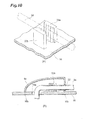
- FIG. 10 to FIG 15 show specific examples of the fixing unit.
- the cover 6 shown in FIG. 10 to FIG. 15 is the cover 6c and the package 2 is the package 2c (see FIG. 6 ), however, this is not always the case and the cover may be any one of the covers 6a to 6d and the package may be any one of the packages 2a to 2d.
- FIG. 10 is a perspective view showing the fixing unit
- FIG. 10 is a diagram showing a cross-sectional structure of the intraoral sensor along the line I-I in FIG. 1 .
- the fixing unit shown in FIG. 10 includes the fixing member 32a (first fixing member) and the fixing member 32b (second fixing member).
- the fixing members 32a and 32b are arranged, in a manner to sandwich the signal cable 24, to face each other on the outer surface of the second plate-shaped portion 16.
- the fixing members 32a and 32b have a plate shape and are similar in dimension.
- a plurality of grooves are respectively formed.
- the plurality of grooves extend parallel to one another toward the upper side of the second plate-shaped portion 16.
- FIG. 11 is a perspective view showing the fixing unit
- FIG. 11 is a diagram showing a cross-sectional structure of the intraoral sensor along the line I-I in FIG. 1 .
- the fixing unit shown in FIG. 11 includes the fixing member 32a, the fixing member 32b, and a fixing member 46 (third fixing member).
- the fixing member 46 is arranged on the inner surface of the cover 6c, and placed between the fixing member 32a and the fixing member 32b. It is preferable that the width of the fixing member 46 be smaller than the diameter of the signal cable 24.
- the width of the fixing member 46 is the dimension of the fixing member 46 along a direction perpendicular to a direction in which the signal cable 24 extends.
- the fixing member 46 comes into contact with the signal cable 24 and presses the signal cable 24 against the side of the second plate-shaped portion 16. Due to the function of sandwiching the signal cable 24 by the fixing members 32a and 32b, and the function of pressing the same by the fixing member 46 against the side of the second plate-shaped portion 16, the signal cable 24 becomes capable of being firmly fixed to the package 2c.
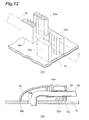
- the fixing unit shown in FIG. 12 will be described.
- (A) in FIG. 12 is a perspective view showing the fixing unit
- (B) in FIG. 12 is a diagram showing a cross-sectional structure of the intraoral sensor along the line I-I in FIG. 1 .
- the fixing unit shown in FIG. 12 includes the fixing member 32a, the fixing member 32b, a fixing member 48a (fourth fixing member), and a fixing member 48b (fifth fixing member).
- the fixing members 48a and 48b are arranged, in a manner to sandwich the signal cable 24, on the inner surface of the cover 6c.
- the fixing members 48a and 48b have a plate shape and are similar in dimension.
- a plurality of grooves are respectively formed.
- the plurality of grooves extend parallel to one another toward the upper side of the second plate-shaped portion 16.
- the fixing members 48a and 32a are sequentially placed along a direction in which the signal cable 24 extends from the opening 16a, and also the fixing members 48b and 32b are sequentially placed along this direction.
- the fixing members 48a and 48b first sandwich and hold the signal cable 24 extending from the opening 16a, and the fixing members 32a and 32b further sandwich and hold the signal cable 24 extending from the fixing members 48a and 48b. Therefore, due to the function of sandwiching the signal cable 24 by the fixing members 48a and 48b, and the function of sandwiching the signal cable 24 by the fixing members 32a and 32b, the signal cable 24 becomes capable of being more firmly fixed to the package 2c.
- a configuration in which the position of the fixing members 48a and 48b is replaced by the position of the fixing members 32a and 32b may be optionally adopted. Moreover, a configuration in which only the fixing members 48a and 48b are arranged without the fxing members 32a and 32b may also be adopted.
- FIG. 13 is a perspective view showing the fixing unit
- FIG. 13 is a diagram showing a cross-sectional structure of the intraoral sensor along the line I-I in FIG. 1 .
- the fixing unit shown in FIG. 13 includes the fixing member 32a, the fixing member 32b, and a fixing member 50 (third fixing member).
- the fixing member 50 is arranged on the inner surface of the cover 6c, and placed between the fixing member 32a and the fixing member 32b. It is preferable that the width of the fixing member 50 be smaller than the diameter of the signal cable 24.
- the width of the fixing member 50 is the dimension of the fixing member 50 along a direction perpendicular to a direction in which the signal cable 24 extends.
- the fixing member 50 comes into contact with the signal cable 24 and presses the signal cable 24 against the side of the second plate-shaped portion 16.
- a plurality of grooves are formed.
- the plurality of grooves extend parallel to one another along a direction from the fixing member 32a toward the fixing member 32b.
- a plurality of depressed and protruded portions are configured, and by the plurality of depressed and protruded portions provided in the fixing member 50, the signal cable 24 is effectively pressed against the side of the second plate-shaped portion 16. Due to the function of sandwiching the signal cable 24 by the fixing members 32a and 32b, and the function of pressing the same by the fixing member 50 against the side of the second plate-shaped portion 16, the signal cable 24 becomes capable of being firmly fixed to the package 2c.
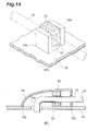
- FIG. 14 is a perspective view showing the fixing unit
- FIG. 14 is a diagram showing a cross-sectional structure of the intraoral sensor along the line I-I in FIG. 1 .
- the fixing unit shown in FIG. 14 includes the fixing member 32a, the fixing member 32b, the fixing member 50, and a fixing member 52 (sixth fixing member).
- the fixing member 52 is arranged on the outer surface of the second plate-shaped portion 16, and placed between the fixing member 32a and the fixing member 32b. It is preferable that the width of the fixing member 52 be smaller than the diameter of the signal cable 24.
- the width of the fixing member 52 is the dimension of the fixing member 52 along a direction perpendicular to a direction in which the signal cable 24 extends.
- the fixing member 52 comes into contact with the signal cable 24, and the signal cable 24 is sandwiched by the fixing member 50 and the fixing member 52.
- a plurality of grooves are formed.
- the plurality of grooves extend parallel to one another along a direction from the fixing member 32a toward the fixing member 32b.
- a plurality of depressed and protruded portions are configured, and by the plurality of depressed and protruded portions provided in the fixing member 52, the signal cable 24 is effectively sandwiched between the fixing member 50 and the fixing member 52. Due to the function of sandwiching the signal cable 24 by the fixing members 32a and 32b, and the function of sandwiching the signal cable 24 by the fixing members 50 and 52, the signal cable 24 becomes capable of being firmly fixed to the package 2c.
- FIG. 15 is a perspective view showing the fixing unit
- FIG. 15 is a diagram showing a cross-sectional structure of the intraoral sensor along the line I-I in FIG. 1 .
- the fixing unit shown in FIG. 15 includes a fixing member 54 (seventh fixing member) and a fixing member 56 (eighth fixing member).
- the fixing member 54 is arranged on the inner surface of the cover 6c, and the fixing member 56 is arranged on the outer surface of the second plate-shaped portion 16. As seen from above the outer surface of the second plate-shaped portion 16, the fixing member 54 and the fixing member 56 are placed in an overlapping manner.
- the fixing member 54 and the fixing member 56 sandwich the signal cable 24.
- a plurality of grooves are formed.
- a plurality of grooves are formed.
- the grooves in the fixing members 54 and 56 are oriented toward the same direction, and oriented perpendicularly to the direction in which the signal cable 24 extends between the fixing members 54 and 56.
- the signal cable 24 is effectively sandwiched between the fixing member 54 and the fixing member 56. Due to the function of sandwiching the signal cable 24 by the fixing members 54 and 56, the signal cable 24 becomes capable of being firmly fixed to the package 2c.
- orientations of the respective grooves in the fixing members 32a, 32b, 48a, 48b, 50, 52, 54, and 56 are not limited to those shown in FIG. 10 to FIG. 15 , and may be optionally directed perpendicularly to those orientations, for example.
- the imaging device of the embodiment is configured to include: a package having a case including a first plate-shaped portion and a second plate-shaped portion facing the first plate-shaped portion, and a cover, arranged on the outer surface of the second plate-shaped portion, for covering an opening formed through the second plate-shaped portion; a photodetecting element having a light incident surface and being contained in the case so that the light incident surface faces the first plate-shaped portion; and a fixing unit, arranged between the second plate-shaped portion and the cover, for fixing to the package a signal cable connected via the opening to the photodetecting element extending from the inside to the outside of the case.
- the case has a first case member including the first plate-shaped portion and a second case member including the second plate-shaped portion, and an end portion of the first case member and an end portion of the second case member that come into contact with each other are fittingly inserted.
- first case member and the second case member are joined through fitted insertion, it becomes possible to avoid a situation where a joint portion between the first case member and the second case member is misaligned.
- the imaging device further includes a plurality of projected pieces arranged on the outer surface of the second plate-shaped portion
- the cover includes a plurality of protrusions, the number of which is equal to that of the projected pieces, at positions corresponding to those of the projected pieces, and the plurality of protrusions are engaged with the plurality of projected pieces, respectively.
- the plurality of projected pieces arranged on the second plate-shaped portion and the plurality of protrusions arranged in the cover are engaged with one another, and thus, the cover is firmly held with the case.
- a groove is formed in a portion that comes into contact with the cover, out of the outer surface of the second plate-shaped portion, and the cover is fitted in the groove.
- the groove is provided, and as a result of the cover being fitted in the groove, the cover and the case are joined. Therefore, the configuration of the cover and the case becomes simple, thereby facilitating the fabrication.
- the imaging device further includes a plurality of bolts
- the cover includes a plurality of skirt portions which come into contact with the outer surface of the second plate-shaped portion and the number of which is equal to that of the plurality of bolts
- bolt holes are respectively provided, in the second plate-shaped portion and the circuit board, bolt holes are respectively provided at positions corresponding to those of the bolt holes of the skirt portions, and into the respective bolt holes of the skirt portions, the second plate-shaped portion, and the circuit board, the bolts are screwed.
- the cover and the case, and the circuit board and the case are bolted, and thus, the cover, the circuit board, and the case are capable of firmly being joined.
- the fixing unit includes the first and second fixing members arranged in a manner to sandwich the signal cable on the outer surface of the second plate-shaped portion.
- the signal cable is capable of being sandwiched by the first and second fixing members, and thus, the signal cable becomes capable of being firmly fixed to the package.
- the fixing unit further includes the third fixing member that is arranged on the inner surface of the cover and placed between the first and second fixing members.
- the signal cable is capable of being sandwiched by the first and second fixing members while being pressed by the third fixing member against the side of the case, and thus, the signal cable becomes capable of being firmly fixed to the package.
- the fixing unit further includes the fourth and fifth fixing members arranged to face each other in a manner to sandwich the signal cable on the inner surface of the cover.
- the signal cable is capable of being sandwiched by the first and second fixing members and the fourth and fifth fixing members, and thus, the signal cable becomes capable of being firmly fixed to the package.
- the fixing unit further includes the sixth fixing member that is arranged on the outer surface of the second plate-shaped portion and placed between the first and second fixing members.
- the signal cable is capable of being sandwiched by the first and second fixing members and the third and sixth fixing members, and thus, the signal cable becomes capable of being firmly fixed to the package.
- the fixing unit includes the seventh fixing member arranged on the outer surface of the second plate-shaped portion and the eighth fixing member arranged on the inner surface of the cover in a manner to overlap the seventh fixing member,
- the signal cable is capable of being sandwiched by the seventh and eighth fixing members, and thus, the signal cable becomes capable of being firmly fixed to the package.
- the present invention is capable of being used as an imaging device in which the connection strength between the package of the imaging device and the signal cable extending from the opposite side of the imaging surface is improved.
Landscapes
- Health & Medical Sciences (AREA)
- Engineering & Computer Science (AREA)
- Life Sciences & Earth Sciences (AREA)
- Medical Informatics (AREA)
- Physics & Mathematics (AREA)
- Signal Processing (AREA)
- Multimedia (AREA)
- Animal Behavior & Ethology (AREA)
- Public Health (AREA)
- Optics & Photonics (AREA)
- Pathology (AREA)
- Radiology & Medical Imaging (AREA)
- Biomedical Technology (AREA)
- Heart & Thoracic Surgery (AREA)
- Molecular Biology (AREA)
- Surgery (AREA)
- High Energy & Nuclear Physics (AREA)
- Nuclear Medicine, Radiotherapy & Molecular Imaging (AREA)
- Veterinary Medicine (AREA)
- General Health & Medical Sciences (AREA)
- Biophysics (AREA)
- Mathematical Physics (AREA)
- Dentistry (AREA)
- Oral & Maxillofacial Surgery (AREA)
- Apparatus For Radiation Diagnosis (AREA)
- Endoscopes (AREA)
- Transforming Light Signals Into Electric Signals (AREA)
- Light Receiving Elements (AREA)
Abstract
Description
- The present invention relates to an imaging device, inserted into an oral cavity, for imaging teeth, etc.
-
Patent Documents 1 to 3 disclose imaging devices for photographing teeth, etc., in an oral cavity. In the case of an intraoral sensor inPatent Document 1, a signal cable is connected to a circuit board on the rear side of an imaging surface. In the case of an X-ray image sensor inPatent Document 2, a signal cable extends via a capsule, a bobbin, etc., on the rear side of an imaging surface. In the case of an intraoral sensor in Patent Document 3, a signal cable is connected to a circuit board on the rear side of an imaging surface via a cap, a sleeve, etc. - Patent Document 1:
U.S. Patent No. 6,652,141 - Patent Document 2:
U.S. Patent No. 6,320,934 - Patent Document 3:
U.S. Patent No. 5,691,539 - In all the sensors described above, the signal cable extends from an opposite side of the imaging surface on which to receive imaging light. Thus, when the sensor is inserted into the oral cavity, the number of opportunities for which the signal cable comes into contact with the oral cavity is decreased, and as a result, discomfort that a patient feels at the time of photographing the oral cavity can be suppressed. However, in the sensor in which the signal cable thus extends from the opposite side of the imaging surface, the discomfort felt by the patient is decreased, and at the same time, the strength for the tension or bending of the signal cable is decreased. Therefore, due to the bending or tension of the signal cable, there is a possibility in such a sensor that a problem occurs to an electrical connection between the signal cable and the sensor.
- Therefore, an object of the present invention is to improve a connection strength between a package of an imaging device and a signal cable extending from an opposite side of an imaging surface.
- An imaging device according to the present invention includes: a package having a case including a first plate-shaped portion and a second plate-shaped portion facing the first plate-shaped portion, and a cover, arranged on an outer surface of the second plate-shaped portion, for covering an opening formed in the second plate-shaped portion; a photodetecting element having a light incident surface and being contained in the case so that the light incident surface faces the first plate-shaped portion; and a fixing unit, arranged between the second plate-shaped portion and the cover, for fixing to the package a signal cable connected to the photodetecting element extending via the opening from the inside to the outside of the case.
- According to the present invention, when the signal cable is pulled out from the opposite side of the photodetecting surface, the signal cable is fixed to the package by the fixing unit. In this way, the signal cable is fixed to the package by the fixing unit, and thus, even when there is bending or tension for the signal cable, it is possible to avoid a situation where a problem occurs to the electrical connection with the signal cable.
- According to the imaging device of the present invention, it is possible to improve a connection strength between a package of an imaging device and a signal cable extending from an opposite side of an imaging surface.
-
- [
FIG. 1] FIG. 1 is a diagram showing an appearance of an intraoral sensor according to an embodiment. - [
FIG. 2] FIG. 2 is a diagram showing a cross-sectional structure of the intraoral sensor according to the embodiment. - [
FIG. 3] FIG. 3 is a perspective view of the intraoral sensor according to the embodiment. - [
FIG. 4] FIG. 4 is a diagram showing a cross-sectional structure of the intraoral sensor according to the embodiment. - [
FIG. 5] FIG. 5 is a perspective view of the intraoral sensor according to the embodiment. - [
FIG. 6] FIG. 6 is a diagram showing a cross-sectional structure of the intraoral sensor according to the embodiment. - [
FIG. 7] FIG. 7 is a perspective view of the intraoral sensor according to the embodiment. - [
FIG. 8] FIG. 8 is a diagram showing a cross-sectional structure of the intraoral sensor according to the embodiment. - [
FIG. 9] FIG. 9 is a perspective view of the intraoral sensor according to the embodiment. - [
FIG. 10] FIG. 10 is a diagram showing a structure of a fixing unit according to the embodiment. - [
FIG. 11] FIG. 11 is a diagram showing a structure of the fixing unit according to the embodiment. - [
FIG. 12] FIG. 12 is a diagram showing a structure of the fixing unit according to the embodiment. - [
FIG. 13] FIG. 13 is a diagram showing a structure of the fixing unit according to the embodiment. - [
FIG. 14] FIG. 14 is a diagram showing a structure of the fixing unit according to the embodiment. - [
FIG. 15] FIG. 15 is a diagram showing a structure of the fixing unit according to the embodiment. - 1, 1a, 1b, 1c, 1d - Intraoral sensor, 10 - Second case member, 12 - First plate-shaped portion, 14 - First side-wall member, 14a, 18a - End portion, 16 - Second plate-shaped portion, 16a - Opening, 16b - Fitting groove, 18 - Second side-wall member, 2, 2a, 2b, 2c, 2d - Package, 20 - Side-wall portion, 22 - Hole portion, 24 - Signal cable, 26a, 26b, 30a, 30b, 38a, 38b - Protrusion, 28a, 28b - Projected piece, 32a, 32b, 46, 48a, 48b, 50, 52, 54, 56 - Fixing member, 34 - Photodetector, 34a - Scintillator, 34c - Circuit board, 34b - Image sensor, 35 - Light incident surface, 36 - Pad, 4 - Case, 40a - Skirt portion, 41a, 43a, 45a, 47a - Bolt hole, 42a - Bolt, 44a - Spacer, 6, 6a, 6c, 6d, 6b - Cover, 8 - First case member.
- Hereinafter, with reference to drawings, a preferable embodiment according to the present invention will be described in detail. In the description of the drawings, where possible, same components are denoted by same reference symbols, and overlapping descriptions will be omitted.
-
FIG. 1 shows an appearance of anintraoral sensor 1 according to an embodiment. Theintraoral sensor 1 is an imaging device, inserted into an oral cavity of a patient, for imaging an X-ray image of teeth, etc., in an oral cavity. Theintraoral sensor 1 is connected to asignal cable 24 extending from a control device for controlling theintraoral sensor 1. Theintraoral sensor 1 is provided with apackage 2. Thepackage 2 includes a first plate-shaped portion 12 and a second plate-shaped portion 16 spaced and facing each other, and a side-wall portion 20 extending between the peripheral edge of the first plate-shaped portion 12 and the peripheral edge of the second plate-shaped portion 16. The side-wall portion 20 includes a first side-wall member 14 extending from the peripheral edge of the first plate-shaped portion 12 and a second side-wall member 18 extending from the peripheral edge of the second plate-shaped portion 16. In the second plate-shaped portion 16, an opening 16a (for example, seeFIG. 2 , etc.) formed through acase 4 from the outside to the inside is provided. - The
package 2 includes thecase 4 and acover 6. Thecase 4 includes afirst case member 8 and asecond case member 10. Thefirst case member 8 includes the first plate-shaped portion 12 and the first side-wall member 14. Thesecond case member 10 includes the second plate-shaped portion 16 and the second side-wall member 18. - The
intraoral sensor 1 includes thecover 6. Thecover 6 is arranged on the outer surface of the second plate-shaped portion 16. Thecover 6 covers the opening 16a (for example, seeFIG. 2 , etc.). Thecover 6 includes ahole portion 22, and thehole portion 22 is formed through thecover 6 from the outside to the inside. Thesignal cable 24 extends from the outside to the inside of thecover 6 via thehole portion 22, and extends, via the opening 16a, from the inside of the cover 6 (outside of the case 4) to the inside of thecase 4. Thesignal cable 24 is connected to a photodetectingelement 34 arranged within the case 4 (for example, seeFIG. 2 , etc.). Here, the X-ray is incident on the first plate-shaped portion 12, and thesignal cable 24 is pulled out from the side of the second plate-shaped portion 16 opposite (on the back surface side of) the first plate-shaped portion 12 on which the X-ray is incident. - The
intraoral sensor 1 includes a fixing unit for fixing thesignal cable 24 to thecase 4. The fixing unit is arranged between the second plate-shapedportion 16 and thecover 6, fixes to thepackage 2 thesignal cable 24 extending, via theopening 16a, from the inside to the outside of thecase 4. Specific examples of the fixing unit are shown inFIG. 10 to FIG. 15 , and will be described in detail later. It is noted that inFIG. 2 to FIG. 9 , the fixing unit (a fixingmember 32a and a fixingmember 32b) shown inFIG. 10 is described as an example. - Next, a specific configuration of the
intraoral sensor 1 will be described. As specific examples of theintraoral sensor 1, anintraoral sensor 1a to anintraoral sensor 1d, respectively shown inFIG. 2 to FIG. 9 , will be described. The configuration of theintraoral sensor 1a is shown inFIG. 2 andFIG. 3 , the configuration of theintraoral sensor 1b is shown inFIG. 4 andFIG. 5 , the configuration of theintraoral sensor 1c is shown inFIG. 6 andFIG. 7 , and the configuration of theintraoral sensor 1d is shown inFIG. 8 andFIG. 9 .FIG. 2 ,FIG. 4 ,FIG. 6 , andFIG. 8 are diagrams showing cross-sectional structures of the intraoral sensor 1 (theintraoral sensor 1a to theintraoral sensor 1d) along a line 1-1 shown inFIG. 1 , andFIG. 3 ,FIG. 5 ,FIG. 7 , andFIG. 9 are perspective views respectively showing theintraoral sensor 1a to theintraoral sensor 1d. - First, with reference to
FIG. 2 to FIG. 9 , the configuration common to theintraoral sensor 1a to theintraoral sensor 1d will be described. Theintraoral sensor 1a to theintraoral sensor 1d include thephotodetecting element 34. Thephotodetecting element 34 is an element for converting an X-ray image into an electrical image signal and outputting it via thesignal cable 24, and is contained in thecase 4. Thephotodetecting element 34 includes ascintillator 34a for converting the X-ray image into visible light, animage sensor 34b for converting the visible light from thescintillator 34a into an electrical image signal, and acircuit board 34c for loading the image signal from theimage sensor 34b. - The
scintillator 34a has alight incident surface 35 on which the X-ray is incident. Theimage sensor 34b is arranged on thescintillator 34a on the opposite side of thelight incident surface 35. Thecircuit board 34c is arranged on theimage sensor 34b. On thecircuit board 34c, a pad 36 (or solder) is provided, and thepad 36 electrically connects an electrical circuit of thecircuit board 34c to thesignal cable 24. Thephotodetecting element 34 is contained in thecase 4 so that thelight incident surface 35 of thescintillator 34a faces the first plate-shapedportion 12 and thecircuit board 34c faces the second plate-shapedportion 16. - Inside of the cover 6 (a
cover 6a to acover 6d) and on the outer surface of the second plate-shapedportion 16, a fixing unit formed by the fixingmember 32a and the fixingmember 32b is arranged. Here, thecover 6a to thecover 6d are specific examples of thecover 6. It is noted that the fixing units arranged in theintraoral sensor 1a to theintraoral sensor 1d are not limited thereto, and any one of the fixing units described inFIG. 10 to FIX. 15 may be adoptable. - A joint portion between the
first case member 8 and thesecond case member 10, i.e., anend portion 14a of the first side-wall member 14 and anend portion 18a of the second side-wall member 18 that come into contact with each other, are fittingly inserted as indicated byreference symbol 4a in the drawing. As a result, thefirst case member 8 and thesecond case member 10 are joined without misalignment. It is noted that thefirst case member 8 and thesecond case member 10 may be fittingly inserted via resin, etc. - Next, with reference to
FIG. 2 andFIG. 3 , a feature of theintraoral sensor 1a will be described. Theintraoral sensor 1a includes apackage 2a and projectedpieces 28a. Thepackage 2a includes thecover 6a and thecase 4. Thepackage 2a and thecover 6a are examples of thepackage 2 and thecover 6, respectively. Thecover 6a includes an end portion that comes into contact with the outer surface of the second plate-shapedportion 16 and a plurality of (in this embodiment, two)protrusions 26a provided at the end portion. Theprotrusions 26a are protruded toward the side covered with thecover 6a (inside of thecover 6a). - The projected
pieces 28a are arranged on the outer surface of the second plate-shapedportion 16 inside of thecover 6a and at the positions corresponding to those of theprotrusions 26a, and the number of projected pieces to be arranged is equal to that of theprotrusions 26a (in this embodiment, two). The two projectedpieces 28a are placed to face each other with theopening 16a being sandwiched therebetween. At the ends of the projectedpieces 28a, theprotrusions 30a are formed. Theprotrusions 30a are protruded toward the opposite sides of directions in which the engagedprotrusions 26a protrude, and thus, theprotrusions 30a are engaged with theprotrusions 26a. As a result of theprotrusions 30a being engaged with theprotrusions 26a, thecover 6a is held with thecase 4. - Next, with reference to
FIG. 4 andFIG. 5 , a feature of theintraoral sensor 1b will be described. Theintraoral sensor 1b includes apackage 2b and projectedpieces 28b. Thepackage 2b includes thecover 6b and thecase 4. Thepackage 2b and thecover 6b are examples of thepackage 2 and thecover 6, respectively. Thecover 6b includes an end portion that comes into contact with the outer surface of the second plate-shapedportion 16 and a plurality of (in this embodiment, two)protrusions 26b provided at the end portion. Theprotrusions 26b are protruded to the side opposite (outside of thecover 6b) the side (inside of thecover 6b) covered with thecover 6b. - The projected
pieces 28b are arranged on the outer surface of the second plate-shapedportion 16 outside of thecover 6b and at the positions corresponding to those of theprotrusions 26b, and the number of projected pieces to be arranged is equal to that of theprotrusions 26b (in this embodiment, two). The two projectedpieces 28b are placed to face each other with theopening 16a being sandwiched therebetween. At the ends of the projectedpieces 28b, theprotrusions 30b are formed. Theprotrusions 30b are protruded toward the opposite sides of directions in which the engagedprotrusions 26b protrude, and thus, theprotrusions 30b are engaged with theprotrusions 26b. As a result of theprotrusions 30b being engaged with theprotrusions 26b, thecover 6b is held with thecase 4. - Next, with reference to
FIG. 6 andFIG. 7 , a feature of theintraoral sensor 1c will be described. Theintraoral sensor 1c is provided with apackage 2c. Thepackage 2c includes thecover 6c and thecase 4. Thepackage 2c and thecover 6c are examples of thepackage 2 and thecover 6, respectively. Thecover 6c includes an end portion that comes into contact with the second plate-shapedportion 16, and on the outer surface of the second plate-shapedportion 16, afitting groove 16b is formed along the end portion of thecover 6c. Theopening 16a, the fixingmember 32a, and the fixingmember 32b are placed within a region surrounded by thefitting groove 16b on the outer surface of the second plate-shapedportion 16. The end portion of thecover 6c is (for example, via resin, etc.) fitted into thefitting groove 16b. In this way, as a result of the end portion of thecover 6c being fitted into thefitting groove 16b (for example, via resin, etc.), thecover 6c is held with thecase 4. - Next, with reference to
FIG. 8 andFIG. 9 , a feature of theintraoral sensor 1d will be described. Theintraoral sensor 1d includes apackage 2d, a plurality ofbolts 42a, and a plurality ofspacers 44a. Thepackage 2d includes thecover 6d and thecase 4. Thepackage 2d and thecover 6d are examples of thepackage 2 and thecover 6, respectively. In thecover 6d, a plurality of (in this embodiment, two)skirt portions 40a are provided at the end portion that comes into contact with the outer surface of the second plate-shapedportion 16. It is noted that thecover 6d may optionally include the single skirt portion extending along the end portion that comes into contact with the outer surface of the second plate-shapedportion 16. - Each of the
skirt portions 40a has a plate shape extending from thecover 6d along the outer surface of the second plate-shapedportion 16, and comes into contact with the outer surface. Theskirt portion 40a protrudes like a plate shape, on the side opposite the side covered with thecover 6d (outside of thecover 6d). Thespacers 44a are arranged between thecircuit board 34c and the second plate-shapedportion 16. The number ofspacers 44a to be arranged is equal to that of theskirt portions 40a (in this embodiment, two). Eachskirt portion 40a is placed on thespacer 44a via the second plate-shapedportion 16. - In the
skirt portions 40a, the second plate-shapedportion 16, thespacers 44a, and thecircuit board 34c, bolt holes into whichbolts 42a are screwed are respectively provided. The bolt holes includebolt holes 41a formed in theskirt portions 40a, bolt holes 43 a formed in the second plate-shapedportion 16,bolt holes 45a formed in thespacers 44a, and boltholes 47a formed in thecircuit board 34c. Thebolt hole 41a is a through hole in theskirt portion 40a, thebolt hole 43a is a through hole in the second plate-shapedportion 16, and thebolt hole 45a is a through hole in thespacer 44a. Thebolt hole 47a is a concave depression formed in thecircuit board 34c, and has a bottom wall inside thereof. - The number of
bolt holes bolts 42a to be arranged are equal to that of theskirt portions 40a (in this embodiment, two). The bolt holes 43a, 45a, and 47a are provided at positions corresponding to those of thebolt holes 41a (where overlapping with thebolt holes 41a as seen from the top of the second plate-shaped portion 16), and thebolt holes bolts 42a are screwed from the bolt holes 41 a. Into a single bolt hole including a set ofbolt holes bolt 42a is screwed. In this way, by means of a bolt fixing using thebolts 42a, thecover 6d and thephotodetecting element 34 are held with thecase 4. - Next, a specific configuration of the fixing unit for fixing the
signal cable 24 to thecase 4 will be described.FIG. 10 to FIG 15 show specific examples of the fixing unit. It is noted that thecover 6 shown inFIG. 10 to FIG. 15 is thecover 6c and thepackage 2 is thepackage 2c (seeFIG. 6 ), however, this is not always the case and the cover may be any one of thecovers 6a to 6d and the package may be any one of thepackages 2a to 2d. - First, the fixing unit shown in
FIG. 10 will be described. (A) inFIG. 10 is a perspective view showing the fixing unit, and (B) inFIG. 10 is a diagram showing a cross-sectional structure of the intraoral sensor along the line I-I inFIG. 1 . The fixing unit shown inFIG. 10 includes the fixingmember 32a (first fixing member) and the fixingmember 32b (second fixing member). The fixingmembers signal cable 24, to face each other on the outer surface of the second plate-shapedportion 16. The fixingmembers - Out of a plurality of surfaces provided in the fixing
member 32a, on a surface facing the fixingmember 32b (surface that comes into contact with the signal cable 24), and out of surfaces provided in the fixingmember 32b, on a surface facing the fixingmember 32a (surface that comes into contact with the signal cable 24), a plurality of grooves are respectively formed. The plurality of grooves extend parallel to one another toward the upper side of the second plate-shapedportion 16. By means of the plurality of grooves, a plurality of depressed and protruded portions are configured in each of the fixingmembers members signal cable 24 is effectively sandwiched between the fixingmember 32a and the fixingmember 32b. Due to the function of sandwiching thesignal cable 24 by the fixingmembers signal cable 24 becomes capable of being firmly fixed to thepackage 2c. - Next, the fixing unit shown in
FIG. 11 will be described. (A) inFIG. 11 is a perspective view showing the fixing unit, and (B) inFIG. 11 is a diagram showing a cross-sectional structure of the intraoral sensor along the line I-I inFIG. 1 . The fixing unit shown inFIG. 11 includes the fixingmember 32a, the fixingmember 32b, and a fixing member 46 (third fixing member). The fixingmember 46 is arranged on the inner surface of thecover 6c, and placed between the fixingmember 32a and the fixingmember 32b. It is preferable that the width of the fixingmember 46 be smaller than the diameter of thesignal cable 24. The width of the fixingmember 46 is the dimension of the fixingmember 46 along a direction perpendicular to a direction in which thesignal cable 24 extends. - Between the fixing
member 32a and the fixingmember 32b, the fixingmember 46 comes into contact with thesignal cable 24 and presses thesignal cable 24 against the side of the second plate-shapedportion 16. Due to the function of sandwiching thesignal cable 24 by the fixingmembers member 46 against the side of the second plate-shapedportion 16, thesignal cable 24 becomes capable of being firmly fixed to thepackage 2c. - The fixing unit shown in
FIG. 12 will be described. (A) inFIG. 12 is a perspective view showing the fixing unit, and (B) inFIG. 12 is a diagram showing a cross-sectional structure of the intraoral sensor along the line I-I inFIG. 1 . The fixing unit shown inFIG. 12 includes the fixingmember 32a, the fixingmember 32b, a fixingmember 48a (fourth fixing member), and a fixingmember 48b (fifth fixing member). The fixingmembers signal cable 24, on the inner surface of thecover 6c. The fixingmembers - Out of a plurality of surfaces provided in the fixing
member 48a, on a surface facing the fixingmember 48b (surface that comes into contact with the signal cable 24), and out of surfaces provided in the fixingmember 48b, on a surface facing the fixingmember 48a (surface that comes into contact with the signal cable 24), a plurality of grooves are respectively formed. The plurality of grooves extend parallel to one another toward the upper side of the second plate-shapedportion 16. By means of the plurality of grooves, a plurality of depressed and protruded portions are configured in each of the fixingmembers members signal cable 24 is effectively sandwiched between the fixingmember 48a and the fixingmember 48b. Due to the function of sandwiching thesignal cable 24 by the fixingmembers signal cable 24 becomes capable of being firmly fixed to thepackage 2c. - Moreover, the fixing
members signal cable 24 extends from theopening 16a, and also the fixingmembers members signal cable 24 extending from theopening 16a, and the fixingmembers signal cable 24 extending from the fixingmembers signal cable 24 by the fixingmembers signal cable 24 by the fixingmembers signal cable 24 becomes capable of being more firmly fixed to thepackage 2c. - It is noted that a configuration in which the position of the fixing
members members members fxing members - Next, the fixing unit shown in
FIG. 13 will be described. (A) inFIG. 13 is a perspective view showing the fixing unit, and (B) inFIG. 13 is a diagram showing a cross-sectional structure of the intraoral sensor along the line I-I inFIG. 1 . The fixing unit shown inFIG. 13 includes the fixingmember 32a, the fixingmember 32b, and a fixing member 50 (third fixing member). The fixingmember 50 is arranged on the inner surface of thecover 6c, and placed between the fixingmember 32a and the fixingmember 32b. It is preferable that the width of the fixingmember 50 be smaller than the diameter of thesignal cable 24. The width of the fixingmember 50 is the dimension of the fixingmember 50 along a direction perpendicular to a direction in which thesignal cable 24 extends. - Between the fixing
member 32a and the fixingmember 32b, the fixingmember 50 comes into contact with thesignal cable 24 and presses thesignal cable 24 against the side of the second plate-shapedportion 16. Out of a plurality of surfaces provided in the fixingmember 50, on a surface facing the second plate-shaped portion 16 (surface that comes into contact with the signal cable 24), a plurality of grooves are formed. The plurality of grooves extend parallel to one another along a direction from the fixingmember 32a toward the fixingmember 32b. By means of the plurality of grooves, a plurality of depressed and protruded portions are configured, and by the plurality of depressed and protruded portions provided in the fixingmember 50, thesignal cable 24 is effectively pressed against the side of the second plate-shapedportion 16. Due to the function of sandwiching thesignal cable 24 by the fixingmembers member 50 against the side of the second plate-shapedportion 16, thesignal cable 24 becomes capable of being firmly fixed to thepackage 2c. - Next, the fixing unit shown in
FIG. 14 will be described. (A) inFIG. 14 is a perspective view showing the fixing unit, and (B) inFIG. 14 is a diagram showing a cross-sectional structure of the intraoral sensor along the line I-I inFIG. 1 . The fixing unit shown inFIG. 14 includes the fixingmember 32a, the fixingmember 32b, the fixingmember 50, and a fixing member 52 (sixth fixing member). The fixingmember 52 is arranged on the outer surface of the second plate-shapedportion 16, and placed between the fixingmember 32a and the fixingmember 32b. It is preferable that the width of the fixingmember 52 be smaller than the diameter of thesignal cable 24. The width of the fixingmember 52 is the dimension of the fixingmember 52 along a direction perpendicular to a direction in which thesignal cable 24 extends. - Between the fixing
member 32a and the fixingmember 32b, the fixingmember 52 comes into contact with thesignal cable 24, and thesignal cable 24 is sandwiched by the fixingmember 50 and the fixingmember 52. Out of a plurality of surfaces provided in the fixingmember 52, on a surface facing the fixing member 50 (surface that comes into contact with the signal cable 24), a plurality of grooves are formed. The plurality of grooves extend parallel to one another along a direction from the fixingmember 32a toward the fixingmember 32b. By means of the plurality of grooves, a plurality of depressed and protruded portions are configured, and by the plurality of depressed and protruded portions provided in the fixingmember 52, thesignal cable 24 is effectively sandwiched between the fixingmember 50 and the fixingmember 52. Due to the function of sandwiching thesignal cable 24 by the fixingmembers signal cable 24 by the fixingmembers signal cable 24 becomes capable of being firmly fixed to thepackage 2c. - Next, the fixing unit shown in
FIG. 15 will be described. (A) inFIG. 15 is a perspective view showing the fixing unit, and (B) inFIG. 15 is a diagram showing a cross-sectional structure of the intraoral sensor along the line I-I inFIG. 1 . The fixing unit shown inFIG. 15 includes a fixing member 54 (seventh fixing member) and a fixing member 56 (eighth fixing member). The fixingmember 54 is arranged on the inner surface of thecover 6c, and the fixingmember 56 is arranged on the outer surface of the second plate-shapedportion 16. As seen from above the outer surface of the second plate-shapedportion 16, the fixingmember 54 and the fixingmember 56 are placed in an overlapping manner. The fixingmember 54 and the fixingmember 56 sandwich thesignal cable 24. - Out of a plurality of surfaces provided in the fixing
member 54, on a surface facing the fixing member 56 (surface that comes into contact with the signal cable 24), a plurality of grooves are formed. Out of a plurality of surfaces provided in the fixingmember 56, on a surface facing the fixing member 54 (surface that comes into contact with the signal cable 24), a plurality of grooves are formed. The grooves in the fixingmembers signal cable 24 extends between the fixingmembers members members signal cable 24 is effectively sandwiched between the fixingmember 54 and the fixingmember 56. Due to the function of sandwiching thesignal cable 24 by the fixingmembers signal cable 24 becomes capable of being firmly fixed to thepackage 2c. - It is noted that the orientations of the respective grooves in the fixing
members FIG. 10 to FIG. 15 , and may be optionally directed perpendicularly to those orientations, for example. - Here, the imaging device of the embodiment is configured to include: a package having a case including a first plate-shaped portion and a second plate-shaped portion facing the first plate-shaped portion, and a cover, arranged on the outer surface of the second plate-shaped portion, for covering an opening formed through the second plate-shaped portion; a photodetecting element having a light incident surface and being contained in the case so that the light incident surface faces the first plate-shaped portion; and a fixing unit, arranged between the second plate-shaped portion and the cover, for fixing to the package a signal cable connected via the opening to the photodetecting element extending from the inside to the outside of the case.
- It is preferable in the imaging device that the case has a first case member including the first plate-shaped portion and a second case member including the second plate-shaped portion, and an end portion of the first case member and an end portion of the second case member that come into contact with each other are fittingly inserted. In this way, because the first case member and the second case member are joined through fitted insertion, it becomes possible to avoid a situation where a joint portion between the first case member and the second case member is misaligned.
- It is preferable that the imaging device further includes a plurality of projected pieces arranged on the outer surface of the second plate-shaped portion, the cover includes a plurality of protrusions, the number of which is equal to that of the projected pieces, at positions corresponding to those of the projected pieces, and the plurality of protrusions are engaged with the plurality of projected pieces, respectively. In this way, the plurality of projected pieces arranged on the second plate-shaped portion and the plurality of protrusions arranged in the cover are engaged with one another, and thus, the cover is firmly held with the case.
- It is preferable in the imaging device that a groove is formed in a portion that comes into contact with the cover, out of the outer surface of the second plate-shaped portion, and the cover is fitted in the groove. In this way, on the surface of the case, the groove is provided, and as a result of the cover being fitted in the groove, the cover and the case are joined. Therefore, the configuration of the cover and the case becomes simple, thereby facilitating the fabrication.
- It is preferable that the imaging device further includes a plurality of bolts, the cover includes a plurality of skirt portions which come into contact with the outer surface of the second plate-shaped portion and the number of which is equal to that of the plurality of bolts, in the plurality of skirt portions, bolt holes are respectively provided, in the second plate-shaped portion and the circuit board, bolt holes are respectively provided at positions corresponding to those of the bolt holes of the skirt portions, and into the respective bolt holes of the skirt portions, the second plate-shaped portion, and the circuit board, the bolts are screwed. In this way, the cover and the case, and the circuit board and the case are bolted, and thus, the cover, the circuit board, and the case are capable of firmly being joined.
- Preferably, in the imaging device, the fixing unit includes the first and second fixing members arranged in a manner to sandwich the signal cable on the outer surface of the second plate-shaped portion. In this way, the signal cable is capable of being sandwiched by the first and second fixing members, and thus, the signal cable becomes capable of being firmly fixed to the package.
- Preferably, in the imaging device, the fixing unit further includes the third fixing member that is arranged on the inner surface of the cover and placed between the first and second fixing members. In this way, the signal cable is capable of being sandwiched by the first and second fixing members while being pressed by the third fixing member against the side of the case, and thus, the signal cable becomes capable of being firmly fixed to the package.
- Preferably, in the imaging device, the fixing unit further includes the fourth and fifth fixing members arranged to face each other in a manner to sandwich the signal cable on the inner surface of the cover. In this way, the signal cable is capable of being sandwiched by the first and second fixing members and the fourth and fifth fixing members, and thus, the signal cable becomes capable of being firmly fixed to the package.
- Preferably, in the imaging device, the fixing unit further includes the sixth fixing member that is arranged on the outer surface of the second plate-shaped portion and placed between the first and second fixing members. In this way, the signal cable is capable of being sandwiched by the first and second fixing members and the third and sixth fixing members, and thus, the signal cable becomes capable of being firmly fixed to the package.
- Preferably, in the imaging device, the fixing unit includes the seventh fixing member arranged on the outer surface of the second plate-shaped portion and the eighth fixing member arranged on the inner surface of the cover in a manner to overlap the seventh fixing member, In this way, the signal cable is capable of being sandwiched by the seventh and eighth fixing members, and thus, the signal cable becomes capable of being firmly fixed to the package.
- The present invention is capable of being used as an imaging device in which the connection strength between the package of the imaging device and the signal cable extending from the opposite side of the imaging surface is improved.
Claims (10)
- An imaging device, comprising:a package having a case including a first plate-shaped portion and a second plate-shaped portion facing the first plate-shaped portion, and a cover, arranged on an outer surface of the second plate-shaped portion, for covering an opening formed in the second plate-shaped portion;a photodetecting element having a light incident surface and being contained in the case so that the light incident surface faces the first plate-shaped portion; anda fixing unit, arranged between the second plate-shaped portion and the cover, for fixing to the package a signal cable connected to the photodetecting element extending via the opening from the inside to the outside of the case.
- The imaging device according to claim 1, wherein
the case has a first case member including the first plate-shaped portion and a second case member including the second plate-shaped portion, and
an end portion of the first case member and an end portion of the second case member that come into contact with each other are fittingly inserted. - The imaging device according to claim 1 or 2, further comprising a plurality of projected pieces arranged on the outer surface of the second plate-shaped portion, wherein
the cover includes a plurality of protrusions, the number of which is equal to that of the projected pieces, at positions corresponding to those of the projected pieces, and
the plurality of protrusions are respectively engaged with the plurality of projected pieces. - The imaging device according to claim 1 or 2, wherein
in a portion that comes into contact with the cover, out of the outer surface of the second plate-shaped portion, a groove is formed, and
the cover is fitted in the groove. - The imaging device according to claim 1 or 2, further comprising a plurality of bolts, wherein
the cover includes a plurality of skirt portions which come into contact with the outer surface of the second plate-shaped portion and the number of which is equal to that of the plurality of bolts,
in the plurality of skirt portions, bolt holes are respectively provided,
in the second plate-shaped portion and a circuit board of the photodetecting element, bolt holes are respectively provided at positions corresponding to those of the bolt holes of the skirt portions, and
into the respective bolt holes of the skirt portions, the second plate-shaped portion, and the circuit board, the bolts are screwed. - The imaging device according to any one of claims 1 to 5,
wherein
the fixing unit includes first and second fixing members arranged to face each other in a manner to sandwich the signal cable on the outer surface of the second plate-shaped portion. - The imaging device according to claim 6, wherein
the fixing unit further includes a third fixing member that is arranged on an inner surface of the cover and placed between the first and second fixing members. - The imaging device according to any one of claims 1 to 6,
wherein
the fixing unit includes fourth and fifth fixing members arranged in a manner to sandwich the signal cable on the inner surface of the cover. - The imaging device according to claim 7, wherein
the fixing unit further includes a sixth fixing member that is arranged on the outer surface of the second plate-shaped portion and placed between the first and second fixing members. - The imaging device according to any one of claims 1 to 5,
wherein
the fixing unit includes a seventh fixing member arranged on the outer surface of the second plate-shaped portion and an eighth fixing member arranged on the inner surface of the cover in a manner to overlap the seventh fixing members.
Applications Claiming Priority (2)
| Application Number | Priority Date | Filing Date | Title |
|---|---|---|---|
| JP2007269467A JP5053793B2 (en) | 2007-10-16 | 2007-10-16 | Image sensor |
| PCT/JP2008/068574 WO2009051103A1 (en) | 2007-10-16 | 2008-10-14 | Imaging device |
Publications (3)
| Publication Number | Publication Date |
|---|---|
| EP2213238A1 true EP2213238A1 (en) | 2010-08-04 |
| EP2213238A4 EP2213238A4 (en) | 2012-01-18 |
| EP2213238B1 EP2213238B1 (en) | 2015-04-15 |
Family
ID=40567367
Family Applications (1)
| Application Number | Title | Priority Date | Filing Date |
|---|---|---|---|
| EP08839456.4A Active EP2213238B1 (en) | 2007-10-16 | 2008-10-14 | Imaging device |
Country Status (5)
| Country | Link |
|---|---|
| US (1) | US8337083B2 (en) |
| EP (1) | EP2213238B1 (en) |
| JP (1) | JP5053793B2 (en) |
| CN (1) | CN101808583B (en) |
| WO (1) | WO2009051103A1 (en) |
Cited By (4)
| Publication number | Priority date | Publication date | Assignee | Title |
|---|---|---|---|---|
| KR20160018139A (en) * | 2014-08-08 | 2016-02-17 | 주식회사 레이언스 | Intraoral sensor |
| US20170224295A1 (en) * | 2014-08-08 | 2017-08-10 | Rayence Co., Ltd. | Intra oral sensor device |
| US9986956B2 (en) | 2014-08-08 | 2018-06-05 | Rayence Co., Ltd. | Image sensor and oral sensor device using same |
| US10092255B2 (en) | 2014-08-08 | 2018-10-09 | Rayence Co., Ltd. | Intraoral sensor |
Families Citing this family (7)
| Publication number | Priority date | Publication date | Assignee | Title |
|---|---|---|---|---|
| US8222610B2 (en) * | 2009-09-02 | 2012-07-17 | Sirona Dental Systems Gmbh | Auxiliary component for medical device having additional functionality |
| JP5979839B2 (en) * | 2011-09-27 | 2016-08-31 | キヤノン株式会社 | X-ray imaging device |
| US9295436B2 (en) | 2013-06-06 | 2016-03-29 | Hamamatsu Photonics K.K. | Method for manufacturing intraoral sensor |
| EP2810601B1 (en) | 2013-06-07 | 2016-12-21 | Hamamatsu Photonics K.K. | Method for manufacturing intraoral sensor |
| KR102305125B1 (en) * | 2014-08-08 | 2021-09-28 | 주식회사 레이언스 | Intraoral sensor apparatus |
| KR101963121B1 (en) | 2014-12-02 | 2019-03-28 | 주식회사 레이언스 | Intraoral sensor |
| US10595797B2 (en) * | 2017-01-31 | 2020-03-24 | Teledyne E2V Semiconductors Sas | Dental intraoral radiological image sensor |
Family Cites Families (8)
| Publication number | Priority date | Publication date | Assignee | Title |
|---|---|---|---|---|
| DE29506839U1 (en) * | 1995-04-22 | 1995-06-22 | Pfeiffer, Manfred, Dr., London | Sensor that can be placed intraorally of a patient's mouth to create a patient's tooth / jaw images |
| JPH10277028A (en) * | 1997-04-08 | 1998-10-20 | Morita Mfg Co Ltd | Dental X-ray image detector and its adapter |
| JP3836208B2 (en) * | 1997-04-09 | 2006-10-25 | 浜松ホトニクス株式会社 | Small medical X-ray image detection device |
| US6320934B1 (en) | 2000-06-26 | 2001-11-20 | Afp Imaging Corporation | Sensor characterization in memory |
| US6652141B1 (en) * | 2002-01-24 | 2003-11-25 | Cygnus Technologies, L.L.C. | Intraoral sensor |
| CN2757341Y (en) * | 2004-11-27 | 2006-02-08 | 深圳富泰宏精密工业有限公司 | Cell lid structure |
| GB0504415D0 (en) * | 2005-03-03 | 2005-04-06 | E2V Tech Uk Ltd | Non-planar x-ray sensor |
| US7973250B2 (en) * | 2006-04-03 | 2011-07-05 | Mack Trucks, Inc. | Cable conduit and method of mounting a cable relative to a wall opening |
-
2007
- 2007-10-16 JP JP2007269467A patent/JP5053793B2/en active Active
-
2008
- 2008-10-14 US US12/682,632 patent/US8337083B2/en active Active
- 2008-10-14 EP EP08839456.4A patent/EP2213238B1/en active Active
- 2008-10-14 CN CN2008801095213A patent/CN101808583B/en active Active
- 2008-10-14 WO PCT/JP2008/068574 patent/WO2009051103A1/en not_active Ceased
Cited By (5)
| Publication number | Priority date | Publication date | Assignee | Title |
|---|---|---|---|---|
| KR20160018139A (en) * | 2014-08-08 | 2016-02-17 | 주식회사 레이언스 | Intraoral sensor |
| US20170224295A1 (en) * | 2014-08-08 | 2017-08-10 | Rayence Co., Ltd. | Intra oral sensor device |
| US9986955B2 (en) * | 2014-08-08 | 2018-06-05 | Rayence Co., Ltd. | Intra oral sensor device |
| US9986956B2 (en) | 2014-08-08 | 2018-06-05 | Rayence Co., Ltd. | Image sensor and oral sensor device using same |
| US10092255B2 (en) | 2014-08-08 | 2018-10-09 | Rayence Co., Ltd. | Intraoral sensor |
Also Published As
| Publication number | Publication date |
|---|---|
| US8337083B2 (en) | 2012-12-25 |
| US20100220839A1 (en) | 2010-09-02 |
| JP2009095464A (en) | 2009-05-07 |
| CN101808583A (en) | 2010-08-18 |
| EP2213238B1 (en) | 2015-04-15 |
| CN101808583B (en) | 2012-08-15 |
| WO2009051103A1 (en) | 2009-04-23 |
| EP2213238A4 (en) | 2012-01-18 |
| JP5053793B2 (en) | 2012-10-17 |
Similar Documents
| Publication | Publication Date | Title |
|---|---|---|
| US8337083B2 (en) | Imaging device | |
| JP3836208B2 (en) | Small medical X-ray image detection device | |
| JP6700667B2 (en) | Radiation imaging apparatus and radiation imaging system | |
| CN102346283A (en) | Optical module | |
| EP2302989A2 (en) | Substrate holding apparatus | |
| JP7102931B2 (en) | Optical connector cable and metal parts | |
| KR101927690B1 (en) | Radiation imaging system | |
| JP5034628B2 (en) | Portable information equipment | |
| EP3053509A1 (en) | Imaging module, and endoscope device | |
| CN110960236A (en) | Radiation detecting apparatus | |
| EP3677188A1 (en) | Intraoral sensor and method for producing intraoral sensor | |
| US10191270B2 (en) | Imaging unit and endoscope apparatus | |
| CN110960237B (en) | Radiation detection device | |
| US10595797B2 (en) | Dental intraoral radiological image sensor | |
| EP4559399A1 (en) | Intraoral image capturing device | |
| JP7350760B2 (en) | power supply | |
| JP4335778B2 (en) | Optical fiber connection structure | |
| JP2021010056A (en) | Imaging device | |
| JP5562056B2 (en) | Electronics | |
| KR20150110881A (en) | Intra-Oral X-ray Sensor Device | |
| JP2012059728A (en) | Optical module | |
| JP2010220000A (en) | Substrate integrated camera module | |
| JPH0571823U (en) | Modular structure | |
| JP2009171046A (en) | Casing structure, assembly method of casing, and disassembling method of the casing | |
| JPH05206660A (en) | Substrate holding device |
Legal Events
| Date | Code | Title | Description |
|---|---|---|---|
| PUAI | Public reference made under article 153(3) epc to a published international application that has entered the european phase |
Free format text: ORIGINAL CODE: 0009012 |
|
| 17P | Request for examination filed |
Effective date: 20100429 |
|
| AK | Designated contracting states |
Kind code of ref document: A1 Designated state(s): AT BE BG CH CY CZ DE DK EE ES FI FR GB GR HR HU IE IS IT LI LT LU LV MC MT NL NO PL PT RO SE SI SK TR |
|
| AX | Request for extension of the european patent |
Extension state: AL BA MK RS |
|
| DAX | Request for extension of the european patent (deleted) | ||
| A4 | Supplementary search report drawn up and despatched |
Effective date: 20111221 |
|
| RIC1 | Information provided on ipc code assigned before grant |
Ipc: H01L 31/02 20060101ALI20111215BHEP Ipc: H04N 5/321 20060101ALI20111215BHEP Ipc: A61B 6/00 20060101ALI20111215BHEP Ipc: A61B 6/14 20060101AFI20111215BHEP |
|
| 17Q | First examination report despatched |
Effective date: 20120924 |
|
| GRAP | Despatch of communication of intention to grant a patent |
Free format text: ORIGINAL CODE: EPIDOSNIGR1 |
|
| INTG | Intention to grant announced |
Effective date: 20140915 |
|
| GRAP | Despatch of communication of intention to grant a patent |
Free format text: ORIGINAL CODE: EPIDOSNIGR1 |
|
| INTG | Intention to grant announced |
Effective date: 20141120 |
|
| GRAS | Grant fee paid |
Free format text: ORIGINAL CODE: EPIDOSNIGR3 |
|
| GRAA | (expected) grant |
Free format text: ORIGINAL CODE: 0009210 |
|
| AK | Designated contracting states |
Kind code of ref document: B1 Designated state(s): AT BE BG CH CY CZ DE DK EE ES FI FR GB GR HR HU IE IS IT LI LT LU LV MC MT NL NO PL PT RO SE SI SK TR |
|
| REG | Reference to a national code |
Ref country code: GB Ref legal event code: FG4D Ref country code: CH Ref legal event code: EP |
|
| REG | Reference to a national code |
Ref country code: IE Ref legal event code: FG4D |
|
| REG | Reference to a national code |
Ref country code: AT Ref legal event code: REF Ref document number: 721490 Country of ref document: AT Kind code of ref document: T Effective date: 20150515 |
|
| REG | Reference to a national code |
Ref country code: DE Ref legal event code: R096 Ref document number: 602008037721 Country of ref document: DE Effective date: 20150528 |
|
| REG | Reference to a national code |
Ref country code: NL Ref legal event code: VDEP Effective date: 20150415 |
|
| REG | Reference to a national code |
Ref country code: AT Ref legal event code: MK05 Ref document number: 721490 Country of ref document: AT Kind code of ref document: T Effective date: 20150415 |
|
| REG | Reference to a national code |
Ref country code: LT Ref legal event code: MG4D |
|
| PG25 | Lapsed in a contracting state [announced via postgrant information from national office to epo] |
Ref country code: NL Free format text: LAPSE BECAUSE OF FAILURE TO SUBMIT A TRANSLATION OF THE DESCRIPTION OR TO PAY THE FEE WITHIN THE PRESCRIBED TIME-LIMIT Effective date: 20150415 |
|
| PG25 | Lapsed in a contracting state [announced via postgrant information from national office to epo] |
Ref country code: NO Free format text: LAPSE BECAUSE OF FAILURE TO SUBMIT A TRANSLATION OF THE DESCRIPTION OR TO PAY THE FEE WITHIN THE PRESCRIBED TIME-LIMIT Effective date: 20150715 Ref country code: LT Free format text: LAPSE BECAUSE OF FAILURE TO SUBMIT A TRANSLATION OF THE DESCRIPTION OR TO PAY THE FEE WITHIN THE PRESCRIBED TIME-LIMIT Effective date: 20150415 Ref country code: PT Free format text: LAPSE BECAUSE OF FAILURE TO SUBMIT A TRANSLATION OF THE DESCRIPTION OR TO PAY THE FEE WITHIN THE PRESCRIBED TIME-LIMIT Effective date: 20150817 Ref country code: ES Free format text: LAPSE BECAUSE OF FAILURE TO SUBMIT A TRANSLATION OF THE DESCRIPTION OR TO PAY THE FEE WITHIN THE PRESCRIBED TIME-LIMIT Effective date: 20150415 Ref country code: HR Free format text: LAPSE BECAUSE OF FAILURE TO SUBMIT A TRANSLATION OF THE DESCRIPTION OR TO PAY THE FEE WITHIN THE PRESCRIBED TIME-LIMIT Effective date: 20150415 |
|
| PG25 | Lapsed in a contracting state [announced via postgrant information from national office to epo] |
Ref country code: LV Free format text: LAPSE BECAUSE OF FAILURE TO SUBMIT A TRANSLATION OF THE DESCRIPTION OR TO PAY THE FEE WITHIN THE PRESCRIBED TIME-LIMIT Effective date: 20150415 Ref country code: IS Free format text: LAPSE BECAUSE OF FAILURE TO SUBMIT A TRANSLATION OF THE DESCRIPTION OR TO PAY THE FEE WITHIN THE PRESCRIBED TIME-LIMIT Effective date: 20150815 Ref country code: GR Free format text: LAPSE BECAUSE OF FAILURE TO SUBMIT A TRANSLATION OF THE DESCRIPTION OR TO PAY THE FEE WITHIN THE PRESCRIBED TIME-LIMIT Effective date: 20150716 Ref country code: AT Free format text: LAPSE BECAUSE OF FAILURE TO SUBMIT A TRANSLATION OF THE DESCRIPTION OR TO PAY THE FEE WITHIN THE PRESCRIBED TIME-LIMIT Effective date: 20150415 |
|
| REG | Reference to a national code |
Ref country code: DE Ref legal event code: R097 Ref document number: 602008037721 Country of ref document: DE |
|
| PG25 | Lapsed in a contracting state [announced via postgrant information from national office to epo] |
Ref country code: EE Free format text: LAPSE BECAUSE OF FAILURE TO SUBMIT A TRANSLATION OF THE DESCRIPTION OR TO PAY THE FEE WITHIN THE PRESCRIBED TIME-LIMIT Effective date: 20150415 Ref country code: DK Free format text: LAPSE BECAUSE OF FAILURE TO SUBMIT A TRANSLATION OF THE DESCRIPTION OR TO PAY THE FEE WITHIN THE PRESCRIBED TIME-LIMIT Effective date: 20150415 |
|
| PLBE | No opposition filed within time limit |
Free format text: ORIGINAL CODE: 0009261 |
|
| STAA | Information on the status of an ep patent application or granted ep patent |
Free format text: STATUS: NO OPPOSITION FILED WITHIN TIME LIMIT |
|
| PG25 | Lapsed in a contracting state [announced via postgrant information from national office to epo] |
Ref country code: PL Free format text: LAPSE BECAUSE OF FAILURE TO SUBMIT A TRANSLATION OF THE DESCRIPTION OR TO PAY THE FEE WITHIN THE PRESCRIBED TIME-LIMIT Effective date: 20150415 Ref country code: CZ Free format text: LAPSE BECAUSE OF FAILURE TO SUBMIT A TRANSLATION OF THE DESCRIPTION OR TO PAY THE FEE WITHIN THE PRESCRIBED TIME-LIMIT Effective date: 20150415 Ref country code: RO Free format text: LAPSE BECAUSE OF NON-PAYMENT OF DUE FEES Effective date: 20150415 Ref country code: SK Free format text: LAPSE BECAUSE OF FAILURE TO SUBMIT A TRANSLATION OF THE DESCRIPTION OR TO PAY THE FEE WITHIN THE PRESCRIBED TIME-LIMIT Effective date: 20150415 |
|
| 26N | No opposition filed |
Effective date: 20160118 |
|
| PG25 | Lapsed in a contracting state [announced via postgrant information from national office to epo] |
Ref country code: LU Free format text: LAPSE BECAUSE OF FAILURE TO SUBMIT A TRANSLATION OF THE DESCRIPTION OR TO PAY THE FEE WITHIN THE PRESCRIBED TIME-LIMIT Effective date: 20151014 Ref country code: SI Free format text: LAPSE BECAUSE OF FAILURE TO SUBMIT A TRANSLATION OF THE DESCRIPTION OR TO PAY THE FEE WITHIN THE PRESCRIBED TIME-LIMIT Effective date: 20150415 |
|
| REG | Reference to a national code |
Ref country code: CH Ref legal event code: PL |
|
| GBPC | Gb: european patent ceased through non-payment of renewal fee |
Effective date: 20151014 |
|
| PG25 | Lapsed in a contracting state [announced via postgrant information from national office to epo] |
Ref country code: MC Free format text: LAPSE BECAUSE OF FAILURE TO SUBMIT A TRANSLATION OF THE DESCRIPTION OR TO PAY THE FEE WITHIN THE PRESCRIBED TIME-LIMIT Effective date: 20150415 |
|
| REG | Reference to a national code |
Ref country code: IE Ref legal event code: MM4A |
|
| PG25 | Lapsed in a contracting state [announced via postgrant information from national office to epo] |
Ref country code: CH Free format text: LAPSE BECAUSE OF NON-PAYMENT OF DUE FEES Effective date: 20151031 Ref country code: GB Free format text: LAPSE BECAUSE OF NON-PAYMENT OF DUE FEES Effective date: 20151014 Ref country code: LI Free format text: LAPSE BECAUSE OF NON-PAYMENT OF DUE FEES Effective date: 20151031 |
|
| PG25 | Lapsed in a contracting state [announced via postgrant information from national office to epo] |
Ref country code: BE Free format text: LAPSE BECAUSE OF FAILURE TO SUBMIT A TRANSLATION OF THE DESCRIPTION OR TO PAY THE FEE WITHIN THE PRESCRIBED TIME-LIMIT Effective date: 20150415 |
|
| REG | Reference to a national code |
Ref country code: FR Ref legal event code: PLFP Year of fee payment: 9 |
|
| PG25 | Lapsed in a contracting state [announced via postgrant information from national office to epo] |
Ref country code: IE Free format text: LAPSE BECAUSE OF NON-PAYMENT OF DUE FEES Effective date: 20151014 |
|
| PG25 | Lapsed in a contracting state [announced via postgrant information from national office to epo] |
Ref country code: BG Free format text: LAPSE BECAUSE OF FAILURE TO SUBMIT A TRANSLATION OF THE DESCRIPTION OR TO PAY THE FEE WITHIN THE PRESCRIBED TIME-LIMIT Effective date: 20150415 Ref country code: HU Free format text: LAPSE BECAUSE OF FAILURE TO SUBMIT A TRANSLATION OF THE DESCRIPTION OR TO PAY THE FEE WITHIN THE PRESCRIBED TIME-LIMIT; INVALID AB INITIO Effective date: 20081014 |
|
| PG25 | Lapsed in a contracting state [announced via postgrant information from national office to epo] |
Ref country code: CY Free format text: LAPSE BECAUSE OF FAILURE TO SUBMIT A TRANSLATION OF THE DESCRIPTION OR TO PAY THE FEE WITHIN THE PRESCRIBED TIME-LIMIT Effective date: 20150415 Ref country code: SE Free format text: LAPSE BECAUSE OF FAILURE TO SUBMIT A TRANSLATION OF THE DESCRIPTION OR TO PAY THE FEE WITHIN THE PRESCRIBED TIME-LIMIT Effective date: 20150415 |
|
| PG25 | Lapsed in a contracting state [announced via postgrant information from national office to epo] |
Ref country code: TR Free format text: LAPSE BECAUSE OF FAILURE TO SUBMIT A TRANSLATION OF THE DESCRIPTION OR TO PAY THE FEE WITHIN THE PRESCRIBED TIME-LIMIT Effective date: 20150415 Ref country code: MT Free format text: LAPSE BECAUSE OF FAILURE TO SUBMIT A TRANSLATION OF THE DESCRIPTION OR TO PAY THE FEE WITHIN THE PRESCRIBED TIME-LIMIT Effective date: 20150415 |
|
| REG | Reference to a national code |
Ref country code: FR Ref legal event code: PLFP Year of fee payment: 10 |
|
| REG | Reference to a national code |
Ref country code: FR Ref legal event code: PLFP Year of fee payment: 11 |
|
| P01 | Opt-out of the competence of the unified patent court (upc) registered |
Effective date: 20230509 |
|
| REG | Reference to a national code |
Ref country code: DE Ref legal event code: R079 Ref document number: 602008037721 Country of ref document: DE Free format text: PREVIOUS MAIN CLASS: A61B0006140000 Ipc: A61B0006510000 |
|
| PGFP | Annual fee paid to national office [announced via postgrant information from national office to epo] |
Ref country code: IT Payment date: 20250922 Year of fee payment: 18 |
|
| PGFP | Annual fee paid to national office [announced via postgrant information from national office to epo] |
Ref country code: FR Payment date: 20250908 Year of fee payment: 18 |
|
| PGFP | Annual fee paid to national office [announced via postgrant information from national office to epo] |
Ref country code: DE Payment date: 20250902 Year of fee payment: 18 |
|
| PGFP | Annual fee paid to national office [announced via postgrant information from national office to epo] |
Ref country code: FI Payment date: 20251014 Year of fee payment: 18 |