EP2212609B1 - Double block and bleed plug - Google Patents
Double block and bleed plug Download PDFInfo
- Publication number
- EP2212609B1 EP2212609B1 EP08847229.5A EP08847229A EP2212609B1 EP 2212609 B1 EP2212609 B1 EP 2212609B1 EP 08847229 A EP08847229 A EP 08847229A EP 2212609 B1 EP2212609 B1 EP 2212609B1
- Authority
- EP
- European Patent Office
- Prior art keywords
- pipe
- plugging head
- plugging
- head
- wheel
- Prior art date
- Legal status (The legal status is an assumption and is not a legal conclusion. Google has not performed a legal analysis and makes no representation as to the accuracy of the status listed.)
- Active
Links
Images





Classifications
-
- F—MECHANICAL ENGINEERING; LIGHTING; HEATING; WEAPONS; BLASTING
- F16—ENGINEERING ELEMENTS AND UNITS; GENERAL MEASURES FOR PRODUCING AND MAINTAINING EFFECTIVE FUNCTIONING OF MACHINES OR INSTALLATIONS; THERMAL INSULATION IN GENERAL
- F16L—PIPES; JOINTS OR FITTINGS FOR PIPES; SUPPORTS FOR PIPES, CABLES OR PROTECTIVE TUBING; MEANS FOR THERMAL INSULATION IN GENERAL
- F16L55/00—Devices or appurtenances for use in, or in connection with, pipes or pipe systems
- F16L55/10—Means for stopping flow in pipes or hoses
- F16L55/12—Means for stopping flow in pipes or hoses by introducing into the pipe a member expandable in situ
- F16L55/128—Means for stopping flow in pipes or hoses by introducing into the pipe a member expandable in situ introduced axially into the pipe or hose
- F16L55/132—Means for stopping flow in pipes or hoses by introducing into the pipe a member expandable in situ introduced axially into the pipe or hose the closure device being a plug fixed by radially deforming the packing
-
- F—MECHANICAL ENGINEERING; LIGHTING; HEATING; WEAPONS; BLASTING
- F16—ENGINEERING ELEMENTS AND UNITS; GENERAL MEASURES FOR PRODUCING AND MAINTAINING EFFECTIVE FUNCTIONING OF MACHINES OR INSTALLATIONS; THERMAL INSULATION IN GENERAL
- F16L—PIPES; JOINTS OR FITTINGS FOR PIPES; SUPPORTS FOR PIPES, CABLES OR PROTECTIVE TUBING; MEANS FOR THERMAL INSULATION IN GENERAL
- F16L55/00—Devices or appurtenances for use in, or in connection with, pipes or pipe systems
- F16L55/10—Means for stopping flow in pipes or hoses
- F16L55/12—Means for stopping flow in pipes or hoses by introducing into the pipe a member expandable in situ
- F16L55/124—Means for stopping flow in pipes or hoses by introducing into the pipe a member expandable in situ introduced radially into the pipe or hose
-
- Y—GENERAL TAGGING OF NEW TECHNOLOGICAL DEVELOPMENTS; GENERAL TAGGING OF CROSS-SECTIONAL TECHNOLOGIES SPANNING OVER SEVERAL SECTIONS OF THE IPC; TECHNICAL SUBJECTS COVERED BY FORMER USPC CROSS-REFERENCE ART COLLECTIONS [XRACs] AND DIGESTS
- Y10—TECHNICAL SUBJECTS COVERED BY FORMER USPC
- Y10T—TECHNICAL SUBJECTS COVERED BY FORMER US CLASSIFICATION
- Y10T137/00—Fluid handling
- Y10T137/0318—Processes
- Y10T137/0402—Cleaning, repairing, or assembling
- Y10T137/0441—Repairing, securing, replacing, or servicing pipe joint, valve, or tank
Definitions
- sealing element 62 When sealing element 62 is in its final sealing position, its outer surface is engaged with the inner wall of pipe P and wheels 82, 84, and 86 do not impinge on any portion of the pipe P. Pivot arm 72 and pivot arm wheel 74 are held in an outward-facing position against the pipe P by spring 78.
Landscapes
- Engineering & Computer Science (AREA)
- General Engineering & Computer Science (AREA)
- Mechanical Engineering (AREA)
- Pipe Accessories (AREA)
- Quick-Acting Or Multi-Walled Pipe Joints (AREA)
- Cleaning By Liquid Or Steam (AREA)
Description
- This invention relates generally to pipe plugs, particularly plugs for use in pipelines that carry high or low pressure fluids, high or low temperature fluids, steam, dangerous fluids, and environmentally hazardous fluids.
- "Double block and bleed" is a well-known term of art that refers to setting two seals in a pipe and opening a bleed port between the seals to ensure that the first seal is holding. Any leakage past the first seal is contained by the second seal and forced to exit through the bleed port. This arrangement ensures that the pipe is completely sealed, making it safe to work on downstream of the two seals.
- Achieving double-block and bleed, however, currently requires the use of a single, metal-to-metal plugging seal or the use of two independent pluggers and fittings. Both approaches are expensive; use relatively large, heavy components; and require a lot of equipment to properly install. Additionally, the metal-to-metal plugging seal approach does not allow for bypassing pipeline product through a fitting. If a bypass is required, a second fitting must be installed upstream of the plugging seal. Therefore, a need exists for a double block and bleed plug that is less expensive, smaller and lighter weight, and easier to install than the current approaches. None of the prior art alone or in combination meets this need or renders the present invention obvious.
- For additional information relating to pipe pluggers, reference may be had to the following previously issued United States patents.
Patent Number Inventor Title 386,446 Bailey Apparatus For Detecting Leaks In Soil and Other Pipes 411,978 Chisholm Pipe Stopper 1,181,984 Arni Test Plug 1,221,733 Henderson Test Plug 2,279,257 Svirsky Expansible Closure Means For Conduits 2,812,778 Ver Nooy Pipe Line Plugger 2,886,068 Ver Nooy Pipe Line Plugger 2,906,295 Ver Nooy Pipe Line Plugger 3,154,106 Ver Nooy Pipeline Plugger 3,442,294 Bischoff et al. Closure Means For Use During Pressure Testing Of Pipes or The Like 3,665,966 Ver Nooy Pipe Plugger 3,774,646 Smith Line Stopping Assembly Using An Inflatable Element 3,774,647 Saha et al. Line Stopping Assembly Using An Inflatable Element 3,902,528 Tartabini et al. Pneumatic Plug For Hydraulic Conduits 4,040,450 Boundy Pipe Scaling Apparatus 4,064,912 Petrone Gas Main Stopper 4,202,377 Harrison Pipe Cleaning and Plugging Apparatus 4,505,295 Quin et al. Apparatus For Inserting A Shut-Off Device Laterally Into A Pipe 4,682,631 Wilger et al. Sealing Apparatus For A Valve Body Opening 5,029,614 Lara et al. Tandem Seal System For Testing Pipelines 5,082,026 Smith Pipeline Plugger 5,297,581 Godfrey Pipeline Plugger 5,844,127 Berube et al. Apparatus For Isolating or Testing A Pipe Segment 6,062,262 Tash Water Drain Pipe Test Plug Device 6,289,935 Tash Drainpipe Test Plug Device 6,601,437 Gotowik Apparatus For Testing or Isolating A Segment Of Pipe 6,659,133 Russell Insertable Line Stopper Plug For Pipelines 7,240,697 Beebe et al. Apparatus and Method For Isolating and Testing A Segment Of Pipelines 7,270,139 Calkins et al. Cam-Assisted, Wedge Actuated, Metal-to-Metal Seal, Block and Bleed Plugging Tool 7,281,543 Calkins et al. Apparatus, Systems and Methods for Plugging a High Temperature Pipe 2007/0018452 Lee Pipe Interruption Fitting EP 0488966 A1 Ravetti Stopper Device For Gas Tubes -
WO 2004/099661 A1 discloses an apparatus, system and method for plugging a pipe by closing the severed ends of a severed pipeline. -
US 3 626 475 A discloses a plugging apparatus for temporarily plugging pipelines carrying hot fluids having one plug member carrying a sealing element. -
JP H11 125387 A - According to a first aspect of the present invention there is provided a pipe plug according to claim 1.
- The sealing element of the first plugging head is pivotally connected by a yoke to the carrier. The sealing element of the second plugging head is pivotally connected by a yoke to the first plugging head. When lowered through a lateral pipe access connection and placed in a final sealing position within a pipe, the first sealing element prevents flow of product in the pipe and the second sealing element captures any leakage past the first sealing element and forces that leakage out through a fitting. The fitting may be connected to a sleeve welded around the pipe and located downstream of the pipe access connection. The sleeve is required only if the stabilization pad forces on the pipe are excessive. To help position each sealing element within the pipe, the pipe plug includes a set of wheels connected to each plugging head. Each wheel in the set of wheels impinges a portion of the pipe at some point during positioning of the pipe plug within the pipe, thereby causing the sealing elements to rotate into their final sealing position within the pipe. A stabilization pad, connected to a flange on a nosepiece of each plugging head, prevents deformation of the sealing elements.
- A spring-loaded pivot arm, pivot pin, and pivot wheel connected to the second plugging head allow the yoke that connects the two plugging heads to rotate freely into its proper position within a pipe. The pivot arm also has an outward-facing raised taper projection located behind the pivot wheel that helps prevent the pivot wheel from becoming entrapped in a pipe access connection when installing the pipe plug into the pipe or removing the pipe plug from the pipe. A guide wheel connected to the first plugging head helps prevent the first plugging head and the yoke connected to the carrier from becoming entrapped during the installation or removal process.
- According to a second aspect of the present invention there is provided a method of double-blocking a pipe according to claim 9.
- A better understanding of the invention will be obtained from the following detailed description of the preferred embodiments taken in conjunction with the drawings and the attached claims
- Preferred embodiments of the invention will now be described in further detail. Other features, aspects, and advantages of the present invention will become better understood with regard to the following detailed description, appended claims, and accompanying drawings (which are not to scale) where:
-
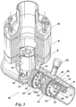
Figure 1 is an isometric view of the pipe plug. -
Figure 2 is a reverse isometric view of the pipe plug. -
Figure 3 is an isometric view of the pipe plug in its final sealing position within a pipe having a bleed port -
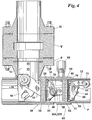
Figure 4 is a view of the pipe plug in its final sealing position within a pipe. -
Figure 5 is a view of the pipe plug as it is being lowered through a pipe access connection. -
Figure 6 is a view of the pipe plug as it begins its transition into the pipe. -
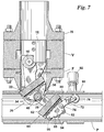
Figure 7 is a view of the pipe plug as it travels along the pipe. -
Figure 8 is a view of the pipe plug as its plugging heads and their sealing elements begin to rotate into a final sealing position within the pipe - It is to be understood that the invention that is now to be described is not limited in its application to the details of the construction and arrangement of the parts illustrated in the accompanying drawings. The invention is capable of other embodiments and of being practiced or carried out in a variety of ways, within the scope of the appended claims.
- Elements shown by the drawings are identified by the following numbers:
- 10
- Pipe plug
- 12
- Carrier
- 14
- Yoke
- 16
- Yoke Pin
- 18
- Yoke Mount
- 20
- Plugging Head
- 22
- Sealing Element
- 24
- Mounting Plate
- 26
- Nosepiece
- 28
- Flange
- 30
- Stabilization Pad
- 32
- Wheel
- 34
- Wheel
- 36
- Guide Wheel
- 38
- Yoke
- 40
- Yoke Pin
- 60
- Plugging Head
- 62
- Sealing Element
- 64
- Mounting Plate
- 66
- Nosepiece
- 68
- Flange
- 70
- Stabilization Pad
- 72
- Pivot Arm
- 74
- Pivot Arm Wheel
- 76
- Pivot Arm Pin
- 78
- Spring
- 80
- Pivot Arm Stop
- 82
- Wheel
- 84
- Wheel
- 86
- Wheel
- 90
- Sleeve
- 92
- Fitting
- Referring to the drawings and first to
Figures 1 and2 , thepipe plug 10 comprises a plugginghead 20 and a plugginghead 60 that are pivotally connected to each other by ayoke 38 that rotates about ayoke pin 40. Plugginghead 20, in turn, is pivotally connected tocarrier 12 byyoke 14.Yoke 14 rotates about ayoke pin 16 contained within ayoke mount 18 connected tocarrier 12.Carrier 12 is well-known in the art and is of the type of control bar head typically used to vertically lower, rotate, and position a plugging head within a pipe P for the purpose of temporarily blocking the pipe P. Similarly, plugginghead 20 and plugginghead 60 also are well-known in the art and are of the type typically used to temporarily block a pipe P. - Plugging
head 20 includes a sealingelement 22, a mountingplate 24, and anosepiece 26 having aflange 28. Astabilization pad 30 mounts to flange 28 at a location substantially in line withyoke pin 16.Stabilization pad 30 helps prevent deformation of sealingelement 22 by countering the rotational moment generated by seal force aboutyoke pin 16.Flange 28 also includes aguide wheel 36 that helps preventyoke 14 and plugginghead 20 from becoming entrapped in the access connection to pipe P during their installation into and removal from the pipe P. - Plugging
head 60 includes a sealingelement 62, a mountingplate 64, and anosepiece 66 having aflange 68. To ensure thatyoke 38 rotates freely into its proper position within the pipe P, apivot arm 72 is rotationally affixed toflange 68. Thepivot arm 72 includes apivot wheel 74,pivot arm pin 76, andspring 78. Thespring 78, along with two pivot arm stops 80 mounted tonosepiece 66, allows thepivot arm 72 to rotate outward and hold its position. Outward-facing projections on thepivot arm 72 and located substantially right behindpivot arm wheel 74 help prevent thepivot arm wheel 74 from becoming entangled in the access connection to pipe during installation of the second plugginghead 60. Astabilization pad 70 mounts to flange 68 at a location substantially opposite that ofpivot arm 72.Stabilization pad 70 helps prevent deformation of sealingelement 62 by countering the rotational moment generated by seal force aboutyoke pin 40. - Referring now to
Figures 3 and4 , pipe plug 10 travels downwardly through an access connection—typically comprised of a housing H, sandwich valve V, and fitting F—until yoke mount 18 comes to rest on a bottom portion of the pipe P, with plugginghead 20 and plugginghead 60 substantially aligned with each other and sealingelements element 22 is in its final sealing position, its outer surface of sealing element is engaged with the inner wall of pipe P andwheels guide wheel 36, do not impinge on any portion of the pipe P. In this position, sealingelement 22 prevents flow of product in the pipe P. When sealingelement 62 is in its final sealing position, its outer surface is engaged with the inner wall of pipe P andwheels P. Pivot arm 72 andpivot arm wheel 74 are held in an outward-facing position against the pipe P byspring 78. - Sealing
element 62 captures any leakage past sealingelement 22 and forces that leakage out through a fitting 92. Fitting 92 may be connected to asleeve 90 welded around the pipe and located downstream of the pipe P access connection. Fitting 92 is of the type well-known in the art to provide a bleed port. - As illustrated by
Figures 5 and6 , pipe plug 10 travels downwardly through housing H, sandwich valve V, and fitting F, untilpivot arm wheel 74 impinges on a bottom portion of pipe P, causingyoke 38 to begin rotation aboutyoke pin 40. As pipe plug 10 is further lowered into the fitting,yoke 38 continues to rotate aboutyoke pin 40 untilwheel 82 impinges a bottom portion of pipe P. As illustrated byFigure 7 , the rotation ofyoke 38 continues untilwheel 84 and then wheel 86 impinge on a bottom portion of the pipe. Aswheel 86 impinges on a bottom portion of the pipe P, plugginghead 20 begins its entry into pipe P. As illustrated byFigures 7 and8 , at some point in this process of rotating plugginghead 60,pivot arm wheel 74 impinges on a top portion of pipe P and causespivot arm 72 to rotate out of the way. - Referring once again to
Figure 8 , as plugginghead 60 becomes substantially in alignment with the inside diameter of pipe P,pipe plug 10 continues its downward travel and plugginghead 20 begins its transition into position within pipe P aswheels yoke 14 to rotate aboutyoke pin 16. Asyoke 14 continues to rotate, plugginghead 20 becomes more substantially in alignment with the inside diameter ofpipe P. Wheel 34 then impinges on a bottom portion of pipe P, causingyoke 14 to continue its rotation until sealingelement 22 rotates into a final sealing position. When yoke mount 18 comes to rest on a bottom portion of pipe P, sealingelements Figures 3 and4 ) and pipe plug 10 is stable and capable of resisting pipeline pressure loads. - While the invention has been described with a certain degree of particularity, it is manifest that many changes may be made in the details of construction and the arrangement of components without departing from the scope of this disclosure. It is understood that the invention is not limited to the embodiments set forth herein for purposes of exemplification, but is to be limited only by the scope of the attached claims.
Claims (13)
- A pipe plug (10) for temporarily plugging a pipe, said pipe plug being configured to be lowered through a lateral pipe access connection into a pipe, said pipe plug comprising:a carrier (12) configured to remain in the lateral pipe access connection when the pipe is plugged;a first plugging head (20), said first plugging head having a first circumferential sealing element (22) and a first pivotal connection to said carrier at a first end, said first pivotal connection permitting said first plugging head to rotate relative to said carrier about a first pivot point and traverse a right angle to gain access to an interior space of the pipe;a second plugging head (60), said second plugging head having a second circumferential sealing element (62) and a second pivotal connection to said first plugging head (20), said second pivotal connection permitting said second plugging head to rotate relative to said first plugging head about a second pivot point and traverse a right angle to gain access to the interior space of the pipe.
- A pipe plug according to claim 1 characterised in that there is included a pivot arm (72).
- A pipe plug according to claim 2, characterised in that said pivot arm has at least one outward-facing raised tapered projection.
- A pipe plug according to claim 2, characterised in that said pivot arm further comprises a spring (78), at least one pivot wheel (74), and at least one pivot arm stop (80).
- A pipe plug according to claim 1, characterised in that said first plugging head further comprises at least one guide wheel.
- A pipe plug according to claim 1, characterised in that said first and/or second plugging head has a stabilization pad (30).
- A pipe plug according to claim 1, characterised in that said first plugging head has at least one first plugging head wheel (32A, 32B) located on a surface of said first plugging head, wherein said first plugging head wheel is configured to impinge on a bottom portion of the pipe as said first plugging head begins its transition into position within the pipe.
- A pipe plug according to claim 1, characterised in that said second plugging head has at least one second plugging head wheel (86) located on a surface of said second plugging head, wherein said second plugging head wheel is configured to impinge on a bottom portion of the pipe as said first plugging head begins its entry into the pipe.
- A method of double-blocking a pipe characterised by the steps of:
providing a pipe plug (10) comprising:a carrier (12);a first plugging head (20), said first plugging head having a first circumferential sealing element (22) and a first pivotal connection to said carrier at a first end,a second plugging head (60), said second plugging head having a second circumferential sealing element (62) and a second pivotal connection to said first plugging head (20);lowering the pipe plug (10 through a lateral pipe access connection;rotating the first plugging head (20) and the second plugging head (60) about the first and second pivotal connection respectively as the carrier (12) continues its downward travel through the lateral pipe access connection so that each plugging head traverses a right angle to gain access to an interior space of said pipe, said pipe being connected to and lying nonparallel to the lateral pipe access connection;positioning the first plugging head and the second plugging head into a final sealing position within the pipe, whereby the carrier remains in the lateral pipe access connection; and sealably engaging an internal wall of the pipe with the first and second plugging heads. - A method of double-blocking a pipe according to claim 9 characterised in that said step of rotating the first plugging head is by a yoke (38) that connects the first plugging head to a carrier (12) and articulates about a yoke pin (16).
- A method of double-blocking a pipe according to claim 9 characterised in that said step of rotating the second plugging head is by a yoke (38) that connects the first plugging head to the second plugging head and articulates about a yoke pin (16).
- A method of double-blocking a pipe according to claim 9 characterised in that said step of positioning the first plugging head and the second plugging head is by at least one wheel that impinges upon a portion of the pipe.
- A method of double-blocking a pipe according to claim 9 characterised in that said step of positioning the second plugging head further includes a spring-loaded pivot arm (72) that impinges upon a portion of the pipe.
Applications Claiming Priority (2)
| Application Number | Priority Date | Filing Date | Title |
|---|---|---|---|
| US11/936,182 US7841364B2 (en) | 2007-11-07 | 2007-11-07 | Double block and bleed plug |
| PCT/US2008/081922 WO2009061669A1 (en) | 2007-11-07 | 2008-10-31 | Double block and bleed plug |
Publications (3)
| Publication Number | Publication Date |
|---|---|
| EP2212609A1 EP2212609A1 (en) | 2010-08-04 |
| EP2212609A4 EP2212609A4 (en) | 2013-11-06 |
| EP2212609B1 true EP2212609B1 (en) | 2021-11-24 |
Family
ID=40586923
Family Applications (1)
| Application Number | Title | Priority Date | Filing Date |
|---|---|---|---|
| EP08847229.5A Active EP2212609B1 (en) | 2007-11-07 | 2008-10-31 | Double block and bleed plug |
Country Status (8)
| Country | Link |
|---|---|
| US (1) | US7841364B2 (en) |
| EP (1) | EP2212609B1 (en) |
| AR (1) | AR069236A1 (en) |
| CA (1) | CA2704427C (en) |
| CL (1) | CL2008003319A1 (en) |
| ES (1) | ES2900098T3 (en) |
| PE (1) | PE20091150A1 (en) |
| WO (1) | WO2009061669A1 (en) |
Families Citing this family (23)
| Publication number | Priority date | Publication date | Assignee | Title |
|---|---|---|---|---|
| JP2010514999A (en) * | 2006-12-29 | 2010-05-06 | コリア ウォーター リソーセズ コーポレーション | Fluid breaker for piping and fluid shutoff method using the same |
| CA2742472A1 (en) | 2008-11-13 | 2010-05-20 | Schering Corporation | Gamma secretase modulators |
| KR100998785B1 (en) * | 2009-12-21 | 2010-12-06 | 왕일우 | Fluid shutoff device with sliding double stopper |
| KR101060729B1 (en) * | 2010-03-12 | 2011-08-31 | 주식회사 한국가스기술공사 | Double plugging head for pipe blocking |
| GB2498969B (en) * | 2012-02-01 | 2016-10-19 | Stats (Uk) Ltd | Low pressure hot tap pipeline isolation |
| US20140283926A1 (en) | 2013-03-19 | 2014-09-25 | Joshua Duell | Foldable, Double-Block and Bleed Plugging Tool |
| US10088084B2 (en) | 2013-12-18 | 2018-10-02 | Worldwide Machining & Welding, Inc. | Flanged fittings for pipeline |
| WO2019204878A1 (en) * | 2018-04-26 | 2019-10-31 | I Pipe Ip Pty Ltd | A pipe plug device, a system and methods of use thereof |
| KR102038833B1 (en) * | 2018-07-25 | 2019-10-31 | (주)우신이엔지 | Folding type blocking device having a pressure assist function |
| EP3844431B1 (en) * | 2018-08-30 | 2024-07-24 | Team Industrial Services Inc. | Pipe isolation device |
| US20220275899A1 (en) * | 2019-07-31 | 2022-09-01 | Team Industrial Services, Inc. | Pipe isolation and monitoring system |
| GB2586464B (en) * | 2019-08-18 | 2023-08-02 | Stats Uk Ltd | Pipeline isolation tool, assembly & method |
| US12442478B2 (en) | 2019-12-17 | 2025-10-14 | Team Industrial Services, Inc. | Pipe isolation device with seal |
| RU2747173C1 (en) * | 2020-05-11 | 2021-04-28 | Публичное акционерное общество "ОНХП" | Flat rotary plug |
| WO2022026919A1 (en) | 2020-07-30 | 2022-02-03 | Safe Isolations Llc | Seal assembly for pipeline isolation tool and methods of use |
| US11859752B2 (en) | 2020-08-24 | 2024-01-02 | Safe Isolations Llc | Gripper assembly for pipeline isolation tool and methods of use |
| US11708929B2 (en) | 2020-09-04 | 2023-07-25 | Safe Isolations Llc | Gripper assembly for pipeline isolation tool and methods of use |
| DK4222347T3 (en) | 2020-10-01 | 2026-02-02 | Tdw Delaware Inc | PIPELINE CONNECTOR |
| WO2022094725A1 (en) | 2020-11-09 | 2022-05-12 | EnReach Hot Tap Services Inc. | Isolation tool and methods of isolating a section of pipe or a vessel |
| WO2022119607A1 (en) | 2020-12-04 | 2022-06-09 | Safe Isolations Llc | Activation system for pipeline plug |
| US12359762B2 (en) | 2021-01-20 | 2025-07-15 | Tdw Delaware, Inc. | Pipeline isolation tool with large-gap sealing element having mini pressure heads and iris-like structural sealing elements |
| US12188602B1 (en) * | 2024-01-25 | 2025-01-07 | Weldfit Llc | Sealing plug assemblies, line stop assemblies, and yokes with fluid pathways for line stopping a pipe and methods for the use thereof |
| US20250268243A1 (en) * | 2024-02-22 | 2025-08-28 | David Schuelke | Trenchless, articulating rodent-blocking implement for sewer cleanouts |
Citations (1)
| Publication number | Priority date | Publication date | Assignee | Title |
|---|---|---|---|---|
| JPH11125387A (en) * | 1997-10-20 | 1999-05-11 | Osaka Gas Co Ltd | Mobile type conduit shutoff device |
Family Cites Families (50)
| Publication number | Priority date | Publication date | Assignee | Title |
|---|---|---|---|---|
| US411978A (en) * | 1889-10-01 | John w | ||
| US386446A (en) * | 1888-07-24 | Daniel a | ||
| US789620A (en) * | 1903-12-31 | 1905-05-09 | Henry T Mason | Stopper for boiler-tubes. |
| US888146A (en) * | 1907-05-29 | 1908-05-19 | Thomas Deasy | Duplex testing-plug. |
| US1181984A (en) * | 1915-06-15 | 1916-05-09 | John W Arni | Test-plug. |
| US1221733A (en) * | 1916-08-28 | 1917-04-03 | Watt A Henderson | Test-plug. |
| US1966819A (en) * | 1932-10-08 | 1934-07-17 | Gulf Pipe Line Company | Slugging liquids through conduits and the like |
| US1993307A (en) * | 1933-08-07 | 1935-03-05 | Mentor D Nicholson | Test plug |
| US2177916A (en) * | 1938-06-14 | 1939-10-31 | Robinson | Plumber's test plug |
| US2279257A (en) * | 1941-02-11 | 1942-04-07 | Charles W Sievert | Expansible closure means for conduits |
| US2299434A (en) * | 1941-05-05 | 1942-10-20 | Svirsky Bennett | Plumber's pipe testing device |
| US2812778A (en) * | 1955-10-10 | 1957-11-12 | Williamson Inc T | Pipe line plugger |
| US2906295A (en) * | 1957-07-01 | 1959-09-29 | Williamson Inc T | Pipe line plugger |
| US2886068A (en) * | 1957-07-30 | 1959-05-12 | Williamson Inc T | Pipe line plugger |
| US3154106A (en) * | 1960-10-10 | 1964-10-27 | Williamson Inc T | Pipeline plugger |
| US3442294A (en) * | 1966-01-03 | 1969-05-06 | Bopp & Reuther Gmbh | Closure means for use during pressure testing of pipes or the like |
| US3495546A (en) * | 1967-11-03 | 1970-02-17 | American Mach & Foundry | Speed control device for pipeline inspection apparatus |
| US3626475A (en) * | 1970-01-05 | 1971-12-07 | Williamson Inc T | High temperature pipe-plugging apparatus |
| US3665966A (en) * | 1970-12-14 | 1972-05-30 | Williamson Inc T | Pipe plugger |
| US3695301A (en) * | 1971-06-07 | 1972-10-03 | Halliburton Co | Apparatus and method for pipeline testing |
| US3774647A (en) * | 1971-11-04 | 1973-11-27 | Mueller Co | Line stopping assembly using an inflatable element |
| US3774646A (en) * | 1971-11-24 | 1973-11-27 | Mueller Co | Line stopping assembly using an inflatable element |
| US3835889A (en) * | 1972-03-31 | 1974-09-17 | Halliburton Co | Expandable pipeline plug |
| US3902528A (en) | 1973-06-22 | 1975-09-02 | United Survey Inc | Pneumatic plug for hydraulic conduits |
| US4040450A (en) | 1974-10-28 | 1977-08-09 | Glenys Irene Boundy | Pipe sealing apparatus |
| GB1508807A (en) * | 1975-04-09 | 1978-04-26 | Underground Location Serv Ltd | Pipeline pigs |
| US4064912A (en) | 1975-11-05 | 1977-12-27 | Petrone Joseph A | Gas main stopper |
| US4202377A (en) | 1976-05-11 | 1980-05-13 | Team, Inc. | Pipe cleaning and plugging apparatus |
| US4314577A (en) * | 1979-07-09 | 1982-02-09 | Brister Beryle D | Installation, hydrostatic testing, repair and modification of large diameter fluid transmission lines |
| US4422477A (en) * | 1981-02-27 | 1983-12-27 | Hughes Tool Company | Pressure energized pipeline plug |
| FR2539843A1 (en) | 1983-01-26 | 1984-07-27 | Petroles Cie Francaise | SIDE INSERTION BOX OF A SHUTTER IN A PIPELINE |
| US4682631A (en) | 1986-04-03 | 1987-07-28 | The United States Of America As Represented By The Secretary Of The Navy | Sealing apparatus for a valve body opening |
| US5082026A (en) | 1987-02-17 | 1992-01-21 | Smith Garland Y | Pipeline plugger |
| US5156042A (en) * | 1987-07-17 | 1992-10-20 | Proeco, Inc. | Leak detector |
| US5029614A (en) | 1989-03-20 | 1991-07-09 | Atlantic Richfield Company | Tandem seal system for testing pipelines |
| IT1240576B (en) | 1990-11-26 | 1993-12-17 | Roberto Ravetti | GAS PIPE CLOSING DEVICE. |
| GB9116111D0 (en) | 1991-07-25 | 1991-09-11 | Underpressure Eng Co Ltd | Pipe plugging means |
| US5293903A (en) * | 1992-08-27 | 1994-03-15 | G. A. Murdock, Inc. | T-connector for use in plumbing |
| US5531250A (en) * | 1994-05-05 | 1996-07-02 | Tdw Delaware, Inc. | Device for plugging the interior of a pipe |
| US5844127A (en) | 1995-01-23 | 1998-12-01 | Berube; Guy | Apparatus for isolating or testing a pipe segment |
| US6062262A (en) | 1995-10-10 | 2000-05-16 | Tash; George | Water drain pipe test plug device |
| US5924454A (en) * | 1996-01-29 | 1999-07-20 | Canadian Fracmaster Ltd. | Isolation tool |
| CA2312577C (en) | 2000-06-27 | 2005-02-08 | Horst Gotowik | Apparatus for testing or isolating a segment of pipe |
| US6289935B1 (en) | 2000-08-25 | 2001-09-18 | George Tash | Drainpipe test plug device |
| US6659133B2 (en) | 2001-02-06 | 2003-12-09 | Larry R. Russell | Insertable line stopper plug for pipelines |
| DE602004013304T2 (en) | 2003-05-02 | 2009-05-20 | TDW Delaware, Inc., Wilmington | DEVICES, SYSTEMS AND METHOD FOR LOCKING A HIGH-TEMPERATURE TUBE |
| US7240697B2 (en) | 2004-10-21 | 2007-07-10 | Mechanical Research & Design, Inc. | Apparatus and method for isolating and testing a segment of pipelines |
| US7270139B2 (en) | 2005-04-25 | 2007-09-18 | Tdw Delaware, Inc. | Cam-assisted, wedge actuated, metal-to-metal seal, block and bleed plugging tool |
| KR200399091Y1 (en) | 2005-07-25 | 2005-10-20 | 이우각 | Fitting for intercepting fluid flow in the pipe |
| US8307856B2 (en) * | 2007-11-07 | 2012-11-13 | Tdw Delaware Inc. | Double block and bleed plug |
-
2007
- 2007-11-07 US US11/936,182 patent/US7841364B2/en active Active
-
2008
- 2008-10-31 CA CA2704427A patent/CA2704427C/en active Active
- 2008-10-31 ES ES08847229T patent/ES2900098T3/en active Active
- 2008-10-31 EP EP08847229.5A patent/EP2212609B1/en active Active
- 2008-10-31 WO PCT/US2008/081922 patent/WO2009061669A1/en not_active Ceased
- 2008-11-07 CL CL2008003319A patent/CL2008003319A1/en unknown
- 2008-11-07 AR ARP080104891 patent/AR069236A1/en active IP Right Grant
- 2008-11-07 PE PE2008001900A patent/PE20091150A1/en not_active Application Discontinuation
Patent Citations (1)
| Publication number | Priority date | Publication date | Assignee | Title |
|---|---|---|---|---|
| JPH11125387A (en) * | 1997-10-20 | 1999-05-11 | Osaka Gas Co Ltd | Mobile type conduit shutoff device |
Also Published As
| Publication number | Publication date |
|---|---|
| CA2704427C (en) | 2016-03-29 |
| US20090114301A1 (en) | 2009-05-07 |
| PE20091150A1 (en) | 2009-08-10 |
| WO2009061669A1 (en) | 2009-05-14 |
| AR069236A1 (en) | 2010-01-06 |
| CA2704427A1 (en) | 2009-05-14 |
| CL2008003319A1 (en) | 2010-04-16 |
| US7841364B2 (en) | 2010-11-30 |
| EP2212609A4 (en) | 2013-11-06 |
| EP2212609A1 (en) | 2010-08-04 |
| ES2900098T3 (en) | 2022-03-15 |
Similar Documents
| Publication | Publication Date | Title |
|---|---|---|
| CA2704427C (en) | Double block and bleed plug | |
| AU2009308027B2 (en) | Improved double block and bleed plug | |
| CA2872361C (en) | Resilient plug apparatus and method of use | |
| US4369813A (en) | Pipe stopper method and apparatus | |
| US3626475A (en) | High temperature pipe-plugging apparatus | |
| US7766047B1 (en) | Telescoping double blocking pipe plug | |
| CN102232159A (en) | Cross-line plugging system and locking plug | |
| RU2717177C2 (en) | Tool for operation on pipeline wall and corresponding method | |
| US9297487B2 (en) | Installation of a valve in a pipeline | |
| CN204554225U (en) | The outer pod apertures of a kind of first-aid clamp tears valve self-closing device open | |
| US7270139B2 (en) | Cam-assisted, wedge actuated, metal-to-metal seal, block and bleed plugging tool | |
| CA2515275C (en) | Pressurized fluid line servicing tool | |
| KR102068053B1 (en) | Safe line-stopping method using folding type blocking device having a pressure assist function | |
| KR101437665B1 (en) | Leakage blocking device for oil pipeline theft valve | |
| AU2006251924A1 (en) | Cross-line plugging system and locking plug | |
| JPH11141733A (en) | Valve | |
| JPH0316229B2 (en) |
Legal Events
| Date | Code | Title | Description |
|---|---|---|---|
| PUAI | Public reference made under article 153(3) epc to a published international application that has entered the european phase |
Free format text: ORIGINAL CODE: 0009012 |
|
| 17P | Request for examination filed |
Effective date: 20100517 |
|
| AK | Designated contracting states |
Kind code of ref document: A1 Designated state(s): AT BE BG CH CY CZ DE DK EE ES FI FR GB GR HR HU IE IS IT LI LT LU LV MC MT NL NO PL PT RO SE SI SK TR |
|
| AX | Request for extension of the european patent |
Extension state: AL BA MK RS |
|
| DAX | Request for extension of the european patent (deleted) | ||
| A4 | Supplementary search report drawn up and despatched |
Effective date: 20131008 |
|
| RIC1 | Information provided on ipc code assigned before grant |
Ipc: F16L 55/10 20060101AFI20131001BHEP |
|
| STAA | Information on the status of an ep patent application or granted ep patent |
Free format text: STATUS: EXAMINATION IS IN PROGRESS |
|
| 17Q | First examination report despatched |
Effective date: 20180320 |
|
| REG | Reference to a national code |
Ref country code: DE Ref legal event code: R079 Ref document number: 602008064310 Country of ref document: DE Free format text: PREVIOUS MAIN CLASS: F16L0055100000 Ipc: F16L0055124000 |
|
| GRAP | Despatch of communication of intention to grant a patent |
Free format text: ORIGINAL CODE: EPIDOSNIGR1 |
|
| STAA | Information on the status of an ep patent application or granted ep patent |
Free format text: STATUS: GRANT OF PATENT IS INTENDED |
|
| RIC1 | Information provided on ipc code assigned before grant |
Ipc: F16L 55/124 20060101AFI20210607BHEP Ipc: F16L 55/132 20060101ALI20210607BHEP |
|
| INTG | Intention to grant announced |
Effective date: 20210625 |
|
| GRAA | (expected) grant |
Free format text: ORIGINAL CODE: 0009210 |
|
| STAA | Information on the status of an ep patent application or granted ep patent |
Free format text: STATUS: THE PATENT HAS BEEN GRANTED |
|
| GRAS | Grant fee paid |
Free format text: ORIGINAL CODE: EPIDOSNIGR3 |
|
| AK | Designated contracting states |
Kind code of ref document: B1 Designated state(s): AT BE BG CH CY CZ DE DK EE ES FI FR GB GR HR HU IE IS IT LI LT LU LV MC MT NL NO PL PT RO SE SI SK TR |
|
| REG | Reference to a national code |
Ref country code: GB Ref legal event code: FG4D |
|
| REG | Reference to a national code |
Ref country code: DE Ref legal event code: R096 Ref document number: 602008064310 Country of ref document: DE |
|
| REG | Reference to a national code |
Ref country code: AT Ref legal event code: REF Ref document number: 1450121 Country of ref document: AT Kind code of ref document: T Effective date: 20211215 |
|
| REG | Reference to a national code |
Ref country code: IE Ref legal event code: FG4D |
|
| REG | Reference to a national code |
Ref country code: NL Ref legal event code: FP |
|
| REG | Reference to a national code |
Ref country code: NO Ref legal event code: T2 Effective date: 20211124 |
|
| REG | Reference to a national code |
Ref country code: ES Ref legal event code: FG2A Ref document number: 2900098 Country of ref document: ES Kind code of ref document: T3 Effective date: 20220315 |
|
| REG | Reference to a national code |
Ref country code: LT Ref legal event code: MG9D |
|
| REG | Reference to a national code |
Ref country code: AT Ref legal event code: MK05 Ref document number: 1450121 Country of ref document: AT Kind code of ref document: T Effective date: 20211124 |
|
| PG25 | Lapsed in a contracting state [announced via postgrant information from national office to epo] |
Ref country code: LT Free format text: LAPSE BECAUSE OF FAILURE TO SUBMIT A TRANSLATION OF THE DESCRIPTION OR TO PAY THE FEE WITHIN THE PRESCRIBED TIME-LIMIT Effective date: 20211124 Ref country code: FI Free format text: LAPSE BECAUSE OF FAILURE TO SUBMIT A TRANSLATION OF THE DESCRIPTION OR TO PAY THE FEE WITHIN THE PRESCRIBED TIME-LIMIT Effective date: 20211124 Ref country code: BG Free format text: LAPSE BECAUSE OF FAILURE TO SUBMIT A TRANSLATION OF THE DESCRIPTION OR TO PAY THE FEE WITHIN THE PRESCRIBED TIME-LIMIT Effective date: 20220224 Ref country code: AT Free format text: LAPSE BECAUSE OF FAILURE TO SUBMIT A TRANSLATION OF THE DESCRIPTION OR TO PAY THE FEE WITHIN THE PRESCRIBED TIME-LIMIT Effective date: 20211124 |
|
| PG25 | Lapsed in a contracting state [announced via postgrant information from national office to epo] |
Ref country code: IS Free format text: LAPSE BECAUSE OF FAILURE TO SUBMIT A TRANSLATION OF THE DESCRIPTION OR TO PAY THE FEE WITHIN THE PRESCRIBED TIME-LIMIT Effective date: 20220324 Ref country code: SE Free format text: LAPSE BECAUSE OF FAILURE TO SUBMIT A TRANSLATION OF THE DESCRIPTION OR TO PAY THE FEE WITHIN THE PRESCRIBED TIME-LIMIT Effective date: 20211124 Ref country code: PT Free format text: LAPSE BECAUSE OF FAILURE TO SUBMIT A TRANSLATION OF THE DESCRIPTION OR TO PAY THE FEE WITHIN THE PRESCRIBED TIME-LIMIT Effective date: 20220324 Ref country code: PL Free format text: LAPSE BECAUSE OF FAILURE TO SUBMIT A TRANSLATION OF THE DESCRIPTION OR TO PAY THE FEE WITHIN THE PRESCRIBED TIME-LIMIT Effective date: 20211124 Ref country code: LV Free format text: LAPSE BECAUSE OF FAILURE TO SUBMIT A TRANSLATION OF THE DESCRIPTION OR TO PAY THE FEE WITHIN THE PRESCRIBED TIME-LIMIT Effective date: 20211124 Ref country code: HR Free format text: LAPSE BECAUSE OF FAILURE TO SUBMIT A TRANSLATION OF THE DESCRIPTION OR TO PAY THE FEE WITHIN THE PRESCRIBED TIME-LIMIT Effective date: 20211124 Ref country code: GR Free format text: LAPSE BECAUSE OF FAILURE TO SUBMIT A TRANSLATION OF THE DESCRIPTION OR TO PAY THE FEE WITHIN THE PRESCRIBED TIME-LIMIT Effective date: 20220225 |
|
| PG25 | Lapsed in a contracting state [announced via postgrant information from national office to epo] |
Ref country code: SK Free format text: LAPSE BECAUSE OF FAILURE TO SUBMIT A TRANSLATION OF THE DESCRIPTION OR TO PAY THE FEE WITHIN THE PRESCRIBED TIME-LIMIT Effective date: 20211124 Ref country code: RO Free format text: LAPSE BECAUSE OF FAILURE TO SUBMIT A TRANSLATION OF THE DESCRIPTION OR TO PAY THE FEE WITHIN THE PRESCRIBED TIME-LIMIT Effective date: 20211124 Ref country code: EE Free format text: LAPSE BECAUSE OF FAILURE TO SUBMIT A TRANSLATION OF THE DESCRIPTION OR TO PAY THE FEE WITHIN THE PRESCRIBED TIME-LIMIT Effective date: 20211124 Ref country code: DK Free format text: LAPSE BECAUSE OF FAILURE TO SUBMIT A TRANSLATION OF THE DESCRIPTION OR TO PAY THE FEE WITHIN THE PRESCRIBED TIME-LIMIT Effective date: 20211124 Ref country code: CZ Free format text: LAPSE BECAUSE OF FAILURE TO SUBMIT A TRANSLATION OF THE DESCRIPTION OR TO PAY THE FEE WITHIN THE PRESCRIBED TIME-LIMIT Effective date: 20211124 |
|
| REG | Reference to a national code |
Ref country code: DE Ref legal event code: R097 Ref document number: 602008064310 Country of ref document: DE |
|
| PLBE | No opposition filed within time limit |
Free format text: ORIGINAL CODE: 0009261 |
|
| STAA | Information on the status of an ep patent application or granted ep patent |
Free format text: STATUS: NO OPPOSITION FILED WITHIN TIME LIMIT |
|
| 26N | No opposition filed |
Effective date: 20220825 |
|
| PG25 | Lapsed in a contracting state [announced via postgrant information from national office to epo] |
Ref country code: SI Free format text: LAPSE BECAUSE OF FAILURE TO SUBMIT A TRANSLATION OF THE DESCRIPTION OR TO PAY THE FEE WITHIN THE PRESCRIBED TIME-LIMIT Effective date: 20211124 |
|
| PG25 | Lapsed in a contracting state [announced via postgrant information from national office to epo] |
Ref country code: MC Free format text: LAPSE BECAUSE OF FAILURE TO SUBMIT A TRANSLATION OF THE DESCRIPTION OR TO PAY THE FEE WITHIN THE PRESCRIBED TIME-LIMIT Effective date: 20211124 |
|
| REG | Reference to a national code |
Ref country code: CH Ref legal event code: PL |
|
| P01 | Opt-out of the competence of the unified patent court (upc) registered |
Effective date: 20230522 |
|
| PG25 | Lapsed in a contracting state [announced via postgrant information from national office to epo] |
Ref country code: LU Free format text: LAPSE BECAUSE OF NON-PAYMENT OF DUE FEES Effective date: 20221031 |
|
| PG25 | Lapsed in a contracting state [announced via postgrant information from national office to epo] |
Ref country code: LI Free format text: LAPSE BECAUSE OF NON-PAYMENT OF DUE FEES Effective date: 20221031 Ref country code: CH Free format text: LAPSE BECAUSE OF NON-PAYMENT OF DUE FEES Effective date: 20221031 |
|
| PG25 | Lapsed in a contracting state [announced via postgrant information from national office to epo] |
Ref country code: IE Free format text: LAPSE BECAUSE OF NON-PAYMENT OF DUE FEES Effective date: 20221031 |
|
| PG25 | Lapsed in a contracting state [announced via postgrant information from national office to epo] |
Ref country code: HU Free format text: LAPSE BECAUSE OF FAILURE TO SUBMIT A TRANSLATION OF THE DESCRIPTION OR TO PAY THE FEE WITHIN THE PRESCRIBED TIME-LIMIT; INVALID AB INITIO Effective date: 20081031 |
|
| PG25 | Lapsed in a contracting state [announced via postgrant information from national office to epo] |
Ref country code: CY Free format text: LAPSE BECAUSE OF FAILURE TO SUBMIT A TRANSLATION OF THE DESCRIPTION OR TO PAY THE FEE WITHIN THE PRESCRIBED TIME-LIMIT Effective date: 20211124 |
|
| PG25 | Lapsed in a contracting state [announced via postgrant information from national office to epo] |
Ref country code: TR Free format text: LAPSE BECAUSE OF FAILURE TO SUBMIT A TRANSLATION OF THE DESCRIPTION OR TO PAY THE FEE WITHIN THE PRESCRIBED TIME-LIMIT Effective date: 20211124 |
|
| PG25 | Lapsed in a contracting state [announced via postgrant information from national office to epo] |
Ref country code: MT Free format text: LAPSE BECAUSE OF FAILURE TO SUBMIT A TRANSLATION OF THE DESCRIPTION OR TO PAY THE FEE WITHIN THE PRESCRIBED TIME-LIMIT Effective date: 20211124 |
|
| PGFP | Annual fee paid to national office [announced via postgrant information from national office to epo] |
Ref country code: NL Payment date: 20250917 Year of fee payment: 18 Ref country code: IT Payment date: 20250926 Year of fee payment: 18 |
|
| PGFP | Annual fee paid to national office [announced via postgrant information from national office to epo] |
Ref country code: BE Payment date: 20250917 Year of fee payment: 18 Ref country code: GB Payment date: 20250923 Year of fee payment: 18 |
|
| PGFP | Annual fee paid to national office [announced via postgrant information from national office to epo] |
Ref country code: FR Payment date: 20250916 Year of fee payment: 18 |
|
| PGFP | Annual fee paid to national office [announced via postgrant information from national office to epo] |
Ref country code: DE Payment date: 20250917 Year of fee payment: 18 |
|
| PGFP | Annual fee paid to national office [announced via postgrant information from national office to epo] |
Ref country code: NO Payment date: 20251023 Year of fee payment: 18 |
|
| PGFP | Annual fee paid to national office [announced via postgrant information from national office to epo] |
Ref country code: ES Payment date: 20251111 Year of fee payment: 18 |