EP2212584B1 - Flywheel assembly - Google Patents
Flywheel assembly Download PDFInfo
- Publication number
- EP2212584B1 EP2212584B1 EP08840704A EP08840704A EP2212584B1 EP 2212584 B1 EP2212584 B1 EP 2212584B1 EP 08840704 A EP08840704 A EP 08840704A EP 08840704 A EP08840704 A EP 08840704A EP 2212584 B1 EP2212584 B1 EP 2212584B1
- Authority
- EP
- European Patent Office
- Prior art keywords
- flywheel
- support ribs
- crankshaft
- cooling fan
- ribs
- Prior art date
- Legal status (The legal status is an assumption and is not a legal conclusion. Google has not performed a legal analysis and makes no representation as to the accuracy of the status listed.)
- Not-in-force
Links
- 238000001816 cooling Methods 0.000 claims description 56
- 230000007246 mechanism Effects 0.000 claims description 22
- 238000002485 combustion reaction Methods 0.000 claims description 18
- 238000013016 damping Methods 0.000 claims description 13
- 238000000034 method Methods 0.000 claims description 8
- 230000004044 response Effects 0.000 description 32
- 230000005291 magnetic effect Effects 0.000 description 21
- 238000004458 analytical method Methods 0.000 description 12
- 230000009467 reduction Effects 0.000 description 11
- 230000000295 complement effect Effects 0.000 description 9
- 239000000463 material Substances 0.000 description 7
- 230000000712 assembly Effects 0.000 description 5
- 238000000429 assembly Methods 0.000 description 5
- 239000000696 magnetic material Substances 0.000 description 5
- 239000007858 starting material Substances 0.000 description 5
- 238000005266 casting Methods 0.000 description 4
- 238000010276 construction Methods 0.000 description 4
- 230000000875 corresponding effect Effects 0.000 description 4
- 239000000853 adhesive Substances 0.000 description 3
- 230000001070 adhesive effect Effects 0.000 description 3
- 239000003570 air Substances 0.000 description 3
- 239000003302 ferromagnetic material Substances 0.000 description 3
- XEEYBQQBJWHFJM-UHFFFAOYSA-N Iron Chemical compound [Fe] XEEYBQQBJWHFJM-UHFFFAOYSA-N 0.000 description 2
- PXHVJJICTQNCMI-UHFFFAOYSA-N Nickel Chemical compound [Ni] PXHVJJICTQNCMI-UHFFFAOYSA-N 0.000 description 2
- 235000002595 Solanum tuberosum Nutrition 0.000 description 2
- 244000061456 Solanum tuberosum Species 0.000 description 2
- 229910052782 aluminium Inorganic materials 0.000 description 2
- XAGFODPZIPBFFR-UHFFFAOYSA-N aluminium Chemical compound [Al] XAGFODPZIPBFFR-UHFFFAOYSA-N 0.000 description 2
- 239000012080 ambient air Substances 0.000 description 2
- 239000010941 cobalt Substances 0.000 description 2
- 229910017052 cobalt Inorganic materials 0.000 description 2
- 238000006073 displacement reaction Methods 0.000 description 2
- 230000005294 ferromagnetic effect Effects 0.000 description 2
- 230000003993 interaction Effects 0.000 description 2
- 229910052761 rare earth metal Inorganic materials 0.000 description 2
- 150000002910 rare earth metals Chemical class 0.000 description 2
- 229910000851 Alloy steel Inorganic materials 0.000 description 1
- 229910001018 Cast iron Inorganic materials 0.000 description 1
- 229910000831 Steel Inorganic materials 0.000 description 1
- 238000007792 addition Methods 0.000 description 1
- -1 aluminum-nickel-cobalt Chemical compound 0.000 description 1
- 230000033228 biological regulation Effects 0.000 description 1
- 230000015556 catabolic process Effects 0.000 description 1
- GUTLYIVDDKVIGB-UHFFFAOYSA-N cobalt atom Chemical compound [Co] GUTLYIVDDKVIGB-UHFFFAOYSA-N 0.000 description 1
- 230000002596 correlated effect Effects 0.000 description 1
- 230000001419 dependent effect Effects 0.000 description 1
- 230000009977 dual effect Effects 0.000 description 1
- 230000008030 elimination Effects 0.000 description 1
- 238000003379 elimination reaction Methods 0.000 description 1
- 230000005284 excitation Effects 0.000 description 1
- 229910052742 iron Inorganic materials 0.000 description 1
- 230000007257 malfunction Effects 0.000 description 1
- 238000004519 manufacturing process Methods 0.000 description 1
- 230000013011 mating Effects 0.000 description 1
- 229910052751 metal Inorganic materials 0.000 description 1
- 239000002184 metal Substances 0.000 description 1
- 150000002739 metals Chemical class 0.000 description 1
- 229910052759 nickel Inorganic materials 0.000 description 1
- AJCDFVKYMIUXCR-UHFFFAOYSA-N oxobarium;oxo(oxoferriooxy)iron Chemical compound [Ba]=O.O=[Fe]O[Fe]=O.O=[Fe]O[Fe]=O.O=[Fe]O[Fe]=O.O=[Fe]O[Fe]=O.O=[Fe]O[Fe]=O.O=[Fe]O[Fe]=O AJCDFVKYMIUXCR-UHFFFAOYSA-N 0.000 description 1
- 230000002265 prevention Effects 0.000 description 1
- 230000002787 reinforcement Effects 0.000 description 1
- 238000009877 rendering Methods 0.000 description 1
- 239000007787 solid Substances 0.000 description 1
- 239000010935 stainless steel Substances 0.000 description 1
- 229910001220 stainless steel Inorganic materials 0.000 description 1
- 239000010959 steel Substances 0.000 description 1
- 229910052712 strontium Inorganic materials 0.000 description 1
- CIOAGBVUUVVLOB-UHFFFAOYSA-N strontium atom Chemical compound [Sr] CIOAGBVUUVVLOB-UHFFFAOYSA-N 0.000 description 1
- 230000001629 suppression Effects 0.000 description 1
Images









Classifications
-
- F—MECHANICAL ENGINEERING; LIGHTING; HEATING; WEAPONS; BLASTING
- F16—ENGINEERING ELEMENTS AND UNITS; GENERAL MEASURES FOR PRODUCING AND MAINTAINING EFFECTIVE FUNCTIONING OF MACHINES OR INSTALLATIONS; THERMAL INSULATION IN GENERAL
- F16F—SPRINGS; SHOCK-ABSORBERS; MEANS FOR DAMPING VIBRATION
- F16F15/00—Suppression of vibrations in systems; Means or arrangements for avoiding or reducing out-of-balance forces, e.g. due to motion
- F16F15/30—Flywheels
- F16F15/315—Flywheels characterised by their supporting arrangement, e.g. mountings, cages, securing inertia member to shaft
-
- Y—GENERAL TAGGING OF NEW TECHNOLOGICAL DEVELOPMENTS; GENERAL TAGGING OF CROSS-SECTIONAL TECHNOLOGIES SPANNING OVER SEVERAL SECTIONS OF THE IPC; TECHNICAL SUBJECTS COVERED BY FORMER USPC CROSS-REFERENCE ART COLLECTIONS [XRACs] AND DIGESTS
- Y10—TECHNICAL SUBJECTS COVERED BY FORMER USPC
- Y10T—TECHNICAL SUBJECTS COVERED BY FORMER US CLASSIFICATION
- Y10T74/00—Machine element or mechanism
- Y10T74/21—Elements
- Y10T74/2121—Flywheel, motion smoothing-type
-
- Y—GENERAL TAGGING OF NEW TECHNOLOGICAL DEVELOPMENTS; GENERAL TAGGING OF CROSS-SECTIONAL TECHNOLOGIES SPANNING OVER SEVERAL SECTIONS OF THE IPC; TECHNICAL SUBJECTS COVERED BY FORMER USPC CROSS-REFERENCE ART COLLECTIONS [XRACs] AND DIGESTS
- Y10—TECHNICAL SUBJECTS COVERED BY FORMER USPC
- Y10T—TECHNICAL SUBJECTS COVERED BY FORMER US CLASSIFICATION
- Y10T74/00—Machine element or mechanism
- Y10T74/21—Elements
- Y10T74/2121—Flywheel, motion smoothing-type
- Y10T74/2132—Structural detail, e.g., fiber, held by magnet, etc.
Definitions
- rib as used herein can include terms such as rib portion(s), rib segment(s), struts, rib mechanisms and other similar terms as appropriate.
- the dimensions (e.g., height and width) of the support ribs 26 can vary to convenience depending upon the size and the weight of the flywheel 2.
- each of the lines 106 that form a V or a substantially V-shaped configuration can extend from the inner lip portion 14 ( FIG. 2 ) (e.g., from a point of contact of the outer ribs 31 of FIG. 2 ) of the outer rim 10 ( FIG.
- the lines 108 can extend from one side of the inner lip portion 14 ( FIG. 2 ) of the outer rim 10 ( FIG. 2 ) at a tangent to the inner hub portion 16 ( FIG. 2 ) to the other side of the inner lip portion. Additionally, the lines 106 and 108 are located and oriented in a manner that the lines intersect with one another at a point 35 (See. FIG. 2 ).
- a secure interlock mechanism is provided for rotatably mounting the cooling fan 50 over the flywheel 2.
- the interlock mechanism does not employ rivets, bolts, adhesives or other fastening means that secure the cooling fan 50 permanently to the flywheel 2, the cooling fan can be conveniently replaced without replacing the flywheel.
- FIGS. 5 and 6 exploded and assembled views, respectively, of a flywheel system 61, including the flywheel assembly 62 in operational association with the crankshaft 4 of the crankcase 6 is shown, in accordance with at least some embodiments of the present invention.
- the flywheel 2 is secured to the crankshaft 4 for rotation along the axial axis of the crankshaft by press-fitting the flywheel to the crankshaft in the manner described above.
- the cooling fan 50 is secured for rotation in synchronism with the flywheel and the crankshaft, along the axial axis thereof.
- the cooling fan 50 can be mounted by designing the oblong-shaped or substantially-oblong shaped opening 56 as a clearance fit.
- the press fit mechanism can be used as well.
- the retaining nut 66 then holds the drive cup 64, the cooling fan 50 and the flywheel 2 in position relative to the crankshaft 4 when the flywheel is assembled onto the crankshaft by engaging with the pin-shaped protrusion of the drive cup. Finally, axial pressure applied to the overall assembly of the drive cup 64, the cooling fan 50 and the flywheel 2 by the retaining nut 66 further reinforces the various connections among those components, thereby maintaining the rotational positions of the various components relative to one another and to the crankshaft. Notwithstanding the fact that in the present embodiment, a retaining nut is used for securing the flywheel assembly onto the crankshaft, in other embodiments, rivets, bolts and/or other fastening and engaging means can be employed.
Landscapes
- Engineering & Computer Science (AREA)
- General Engineering & Computer Science (AREA)
- Physics & Mathematics (AREA)
- Acoustics & Sound (AREA)
- Aviation & Aerospace Engineering (AREA)
- Mechanical Engineering (AREA)
- Shafts, Cranks, Connecting Bars, And Related Bearings (AREA)
- Connection Of Motors, Electrical Generators, Mechanical Devices, And The Like (AREA)
Description
- The present invention relates to a flywheel assembly and, more particularly, to a flywheel assembly used in conjunction with a crankshaft of an internal combustion engine, according to the preamble part of claim 1. Such a flywheel is known from
FR 816 886 - Flywheel assemblies are used in a wide variety of applications including, for example, satellite pointing operations, automobiles, telecommunication industry and even some electrification systems. Frequently, flywheel assemblies are mounted for rotation on a crankshaft of an internal combustion engine. Often times, high speed rotation of the engine produce vibrations that can propagate through the crankshaft and out to the flywheel assembly and be radiated as a component of the engine noise. Such vibrations or noises are often undesirable or otherwise objectionable.
- To minimize or possibly even completely eliminate such undesirable/objectionable vibrations and/or noises, many flywheel assemblies employ a damper or a damping mechanism for absorbing and damping vibrations and therefore, a portion of the overall noise. Often, such damping mechanisms are employed in between the crankshaft and the flywheel. Although adequate in most regards, such damping mechanisms are nevertheless inadequate in at least some circumstances. For example, damping mechanisms connected at least indirectly to the flywheel can add to the overall weight of the flywheel, making the flywheel less desirable for internal combustion engines used in applications requiring portability or otherwise having weight restrictions. Additionally, external damping mechanisms are susceptible to damage and breakdown, rendering the damping mechanism and the flywheel to which it is connected, inefficient or possibly even completely incapable of being used.
- It would therefore be advantageous if a flywheel assembly having a more efficient vibration suppression/prevention mechanism is developed. It would further be advantageous if such a damping mechanism is not external or otherwise connected externally to the flywheel, but rather is incorporated into the flywheel structure. Still further, it would be advantageous if a damping mechanism that does not add significantly to the weight of the flywheel is developed.
- In one aspect, the present invention relates to a flywheel according to claim 1. Dependent claim 2 to 6 contain advantageous embodiments
- of the flywheel of claim 1.
- In yet another aspect, the present invention provides a method according to claim 7.
-
Claim 8 to 10 contain advantageous embodiments of the method of claim 7. - Other aspects and embodiments are contemplated and considered within the scope of the invention.
- Features of the present invention which are believed to be novel are set forth with particularity in the appended claims. Embodiments of the invention are disclosed with reference to the accompanying drawings and these embodiments are provided for illustrative purposes only. The invention is not limited in its application to the details of construction or the arrangement of the components illustrated in the drawings. Rather, the invention is capable of other embodiments and/or of being practiced or carried out in other various ways. The drawings illustrate a best mode presently contemplated for carrying out the invention. Like reference numerals are used to indicate like components. In the drawings:
-
FIG. 1 is a perspective view of an underside surface of an exemplary flywheel in accordance with at least some embodiments of the present invention; -
FIG. 2 is a top view of the flywheel ofFIG. 1 , in accordance with at least some embodiments of the present invention; -
FIGS. 2A-2B show the flywheel ofFIGS. 1 and2 having various rib configurations in schematic form, in accordance with at least some alternate embodiments of the present invention; -
FIG. 3 is a top perspective view of a cooling fan for use in conjunction with the flywheel ofFIGS. 1 and2 , in accordance with at least some embodiments of the present invention; -
FIG. 4 is a top view of the cooling fan ofFIG. 3 , in accordance with at least some embodiments of the present invention; -
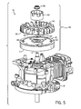
FIG. 5 is an exploded view of an exemplary flywheel assembly shown to include the flywheel ofFIG. 1 and the cooling fan ofFIG. 3 , capable of being mounted on a crankshaft of a crankcase of an internal combustion engine, in accordance with at least some embodiments of the present invention; -
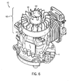
FIG. 6 is an assembled view of the flywheel assembly ofFIG. 5 , in accordance with at least some embodiments of the present invention. -
FIG. 7 shows exemplary perspective views of the cooling fan ofFIG. 3 and a starter cup for operational association with the cooling fan, in accordance with at least some embodiments of the present invention; -
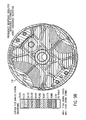
FIG. 8A shows exemplary embodiment(s) of a magnetic group that can be utilized with the flywheel ofFIGS. 1 and2 , in accordance with at least some embodiments of the present invention; -
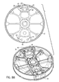
FIG. 8B shows various views of an exemplary flywheel, including a view shown in phantom, incorporating the magnetic group ofFIG. 8A ; -
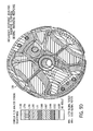
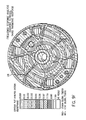
FIGS. 9A-9F provide exemplary test data and analysis results for first, second and third harmonic responses relating to a conventional flywheel and the flywheel ofFIGS. 1 and2 ; and -
FIGS. 10A-10C show exemplary shapes corresponding to the first, second and the third harmonic responses ofFIGS. 9A-9F . - Referring to
FIGS. 1 and2 , top perspective and top views, respectively, of an underside surface of anexemplary flywheel 2, are shown in accordance with at least some embodiments of the present invention. In at least some embodiments of the present invention, theflywheel 2 is intended for use in conjunction with an internal combustion engine (not shown). In particular, the internal combustion engine can be any of a wide variety of engines. For example, some embodiments of the present invention can be employed in conjunction with SORE engines including Class 1 andClass 2 small off-road engines such as those implemented in various machinery and vehicles, including, for example, lawn mowers, snow mobiles and the like. Indeed, in at least some such embodiments, the present invention is intended to be applicable to "non-road engines" as defined in 40 C.F.R. §90.3, which states in pertinent part as follows: "Non-road engine means ... any internal combustion engine: (i) in or on a piece of equipment that is self-propelled or serves a dual purpose by both propelling itself and performing another function (such as garden tractors, off-highway mobile cranes, and bulldozers); or (ii) in or on a piece of equipment that is intended to be propelled while performing its function (such as lawnmowers and string trimmers); or (iii) that, by itself or in or on a piece of equipment, is portable or transportable, meaning designed to be and capable of being carried or moved from one location to another. Indicia of transportability include, but are not limited to, wheels, skids, carrying handles, dolly, trailer, or platform." - The
flywheel 2 ofFIGS. 1 and2 is part of aflywheel assembly 62, described in greater detail inFIGS. 5 and6 . Theflywheel 2 in particular, is mounted for rotation over a central, tapered crankshaft 4 (SeeFIG. 5 ) of a crankcase 6 (SeeFIGS. 5 and6 ) of the internal combustion engine. Additionally, theflywheel 2 is equipped with a damping (also referred herein as stiffening) mechanism, or conduit, for reducing noise and vibrations, produced due to the pulsating characteristics of the engine, which are transmitted through the crankshaft 4 and to theflywheel 2. Further, in the present embodiment, theflywheel 2 includes a solid, rigid, disk-shaped or substantially disk-shaped flywheel body 3, having a thickness that, during normal operation of the engine, on which the flywheel is mounted, experiences rotational movement with minimal or no axial movement. - In addition, in at least some embodiments of the present invention, the
flywheel 2 is a single piece of construction, with all components (described below) integrally formed within the surface of theflywheel body 3. Generally, theflywheel 2 is made of a non-magnetic material such as aluminum, or a ferromagnetic material such as steel. Nevertheless, in other embodiments, different components of theflywheel 2 can be constructed separately (e.g., as separate or distinct components or parts), out of separate ferromagnetic and/or non-magnetic materials, and coupled together in operational association. In alternate embodiments, theflywheel 2, and components thereof, can be made out of ferromagnetic and/or non-magnetic materials other than those provided above, and potentially of magnetic materials as well. - As shown in
FIGS. 1 and2 , theflywheel body 3 includes aninner portion 8 and anouter rim 10 abutting the inner portion, and integrally formed therewith. Theouter rim 10 further includes anouter lip portion 12 and aninner lip portion 14. In at least some embodiments of the present invention, each of the outer and theinner lip portions flywheel 2, theouter rim 10, and the crankshaft 4. Additionally, the size of theflywheel 2 can vary from one embodiment to another. For example, in at least some embodiments of the present invention, the size of theflywheel 2 can be determined from a non-dimensionalized assembled thickness ratio of theouter rim 10. Typically, the non-dimensionalized assembled thickness ratio of an outer rim refers to a ratio of an inner diameter to an outer diameter of the outer rim. - For example, the non- dimensionalized assembled thickness ratio of the
outer rim 10 of the present embodiment can be calculated by determining the ratio of the diameters of theinner lip portion 14 and theouter lip portion 12. Further, in at least some embodiments of the present invention, the non-dimensionalized assembled thickness ratio of theouter rim 10 can be greater than or about 0.8. Nevertheless, in other embodiments, depending upon the application of the internal combustion engine employing theflywheel 2, the non-dimensionalized assembled thickness ratio of theouter rim 10 can be less than or equal to 0.8. - With respect to the
inner portion 8 of theflywheel body 3, the inner portion is further divided into aninner hub portion 16 for linking the flywheel for rotation with the crankshaft 4, and a surroundingouter body portion 17 extending up to theinner lip portion 14 of theouter rim 10. Theinner hub portion 16 further includes anorifice 18, extending axially from a central or a substantially central portion thereof for receiving the crankshaft 4. The crankshaft 4, in particular, is a tapered shaft, continuously tapering from thecrankcase 6 towards the outer end of the shaft. To provide a closely-fitted, self-fitting mechanism for securing theflywheel 2 relative to the crankshaft 4, theorifice 18 is a tapering orifice, which continuously tapers as the orifice extends from the underside surface of theflywheel 2 to the top surface (not shown) of the flywheel. The tapering of theorifice 18 can be clearly seen inFIG. 2 , where theorifice 18 has abroader orifice portion 20 on the underside surface and atapered orifice portion 22 on a top surface 42 (SeeFIG. 5 ) of theflywheel 2. - The
flywheel 2 is mounted onto the crankshaft 4 by virtue of the taperingorifice 18 receiving the tapered crankshaft, and press-fitting the flywheel onto the crankshaft, providing the self-fitting mechanism. In addition to the tapering feature, theorifice 18 has a key-lock feature 24 (SeeFIG. 2 ) extending axially along the inner tapered portions of theorifice 18 for providing a close-fit along the entire periphery of the tapered orifice of theflywheel 2 and the crankshaft 4. - Referring still to
FIGS. 1 and2 , the pulsating characteristics of the engine causes vibrations to be transmitted from the crankshaft 4 to theflywheel 2, with those vibrations being radiated from the flywheel in the form of noise. Insofar as such vibration/noise is undesirable and can otherwise be objectionable, a wide variety of dampers coupled to the flywheel are typically used. Often, such dampers add to the overall weight of the flywheel and cost of the engine. Further, such dampers, due to frictional interaction between the dampers and other moving components connected thereto, are increasingly susceptible to damage and malfunction. - Therefore, to avoid the disadvantages of a conventional damper and to damp undesirable vibrations/noises generated by the flywheel and rotation thereof about the crankshaft, the present invention provides a plurality of
support ribs 26. In addition to reducing and/or eliminating noise, thesupport ribs 26 serve to minimize deflection, resonant response and mass of theflywheel 2. Particularly, thesupport ribs 26 extend between, and are integrally formed with, theinner hub portion 16 and theinner lip portion 14 of theouter rim 10. It shall be understood that terms that are used herein to describe structural and other features, such as "rim", "lip", "hub", and the like are intended to have a broad interpretation. For example, the word "rib" as used herein can include terms such as rib portion(s), rib segment(s), struts, rib mechanisms and other similar terms as appropriate. Further, the dimensions (e.g., height and width) of thesupport ribs 26 can vary to convenience depending upon the size and the weight of theflywheel 2. - Depending upon the positioning of the
support ribs 26 relative to theinner hub portion 16, the support ribs can typically be divided into two types or classes. For example, thesupport ribs 26 can comprise tangential ribs, which are at a tangent, or at least substantially at a tangent, to theinner hub portion 16, and radial ribs, which are positioned radially about the inner hub portion. In at least some embodiments of the present invention, thesupport ribs 26 include a set of eighttangential ribs 28 and tworadial ribs 30. The tworadial ribs 30 are positioned diametrically opposite (e.g., at 180 degrees), or substantially opposite, to one another on the sides of theinner hub portion 16. In at least some embodiments of the present invention, and, as shown, theradial ribs 30 can extend radially or at least substantially radially from theinner hub portion 16 to asemi-cylindrical portion 33 of theflywheel body 3. In at least some other embodiments of the present invention, theradial ribs 30 can extend from theinner hub portion 16 to theinner lip portion 14 of theouter rim 10. - With respect to the tangential ribs, the eight
tangential ribs 28 are further divided into two groups of four ribs each, with each group being placed diametrically opposite (or substantially opposite) to one another, and perpendicular or substantially perpendicular to the tworadial ribs 30. The arrangement of each group of four ribs of the eighttangential ribs 28 relative to theinner hub portion 16 and theradial ribs 30 is described below. In particular, each group includes twoouter ribs 31, positioned to form a V or substantially V-shaped configuration, extending from theinner hub portion 16 to theinner lip 14 of theouter rim 10. Additional reinforcement to theouter ribs 31 can be provided by way ofbosses 29, which are integrally formed within theflywheel body 3. Thebosses 29 typically extend to the other side (e.g., top surface 42) of theflywheel 2, where the bosses form holes for receiving additional components of theflywheel assembly 62, as will be described below. Also, the shape and size of thebosses 29 can vary from one embodiment to another. - Further, each group of the
tangential ribs 28 includes twoinner ribs 33 extending fromsections flywheel body 3, and further intersecting the twoouter ribs 31 at anintersecting region 35. Additionally, the twoinner ribs 33 are in mating alignment with theradial ribs 30 at a tangent to theinner hub portion 16 at anotherintersecting region 39, such that the twoinner ribs 33 are perpendicular or substantially perpendicular to theradial ribs 30. Although an exemplary arrangement of thesupport ribs 26 is described above, in other embodiments, the arrangement of the ribs, and the number of ribs in each class (e.g., tangential and radial ribs) can vary to convenience. Additionally, while the eighttangential ribs 28 and theradial ribs 30, as described here, are discrete ribs intersecting one another at discrete intersecting regions (e.g., intersectingregions 35, 39), it is nevertheless an intention of this invention to include embodiments in which varying rib, rib portions and/or rib sections intersect, and thus are joined and/or connected with one another at one or more intersecting regions. - In general, the orientation and/or arrangement of the
support ribs 26, as described above, reduces and/or eliminates vibrations and any associated noise by virtue of one or more of thesupport ribs 26 interacting with one another. For example, the V or substantially V-shaped outertangential ribs 31 assist in reducing torsional vibrations by way of interaction (e.g., via the connection and/or location of the ribs) with one another. Specifically, theouter rib 31 in the upper left corner interacts with theouter rib 31 in the lower right corner and vice-versa for reducing and/or eliminating vibrations and noise. Relatedly, theouter rib 31 in the upper right corner interacts, and works in concert with theouter rib 31 in the lower left corner and vice versa. Similarly, theradial ribs 30 and the innertangential ribs 33 work in tandem with one another for providing a damping mechanism. - The embodiments discussed above in
FIGS. 1 and2 are exemplary in nature. For example, thesupport ribs 26 can includetangential ribs 28 andradial ribs 30 having various locations and/or orientations. More specifically,FIGS. 2A-2B schematically illustrate some alternative embodiments of the flywheel ofFIGS. 1-2 . For ease of understanding, the variations are shown using lines that are placed or printed in overlay fashion with respect to theflywheel 2 shown inFIGS. 1 and2 . - With specific reference now to
FIG. 2A , in conjunction withFIG. 2 , the radial ribs 30 (FIG. 2 ) have been removed as shown schematically by "X"lines Lines 104 are representative of newly positioned or located tangential ribs 28 (FIG. 2 ). In particular,lines 106 represent the outer tangential ribs 31 (FIG. 2 ) and thelines 108 represent the inner tangential ribs 33 (FIG. 2 ). For example, each of thelines 106 that form a V or a substantially V-shaped configuration can extend from the inner lip portion 14 (FIG. 2 ) (e.g., from a point of contact of theouter ribs 31 ofFIG. 2 ) of the outer rim 10 (FIG. 2 ) to the inner hub portion 16 (FIG. 2 ) (e.g., to a point that is in contact with theradial ribs 30 that can be removed in the embodiment ofFIG. 2A ). Similarly, thelines 108 can extend from one side of the inner lip portion 14 (FIG. 2 ) of the outer rim 10 (FIG. 2 ) at a tangent to the inner hub portion 16 (FIG. 2 ) to the other side of the inner lip portion. Additionally, thelines FIG. 2 ). Further, it will be noted that in at least some embodiments, and as shown, thelines 104 representing the tangential ribs are in addition to thetangential ribs 28 described above with respect toFIGS. 1 and2 , although in other embodiments, this need not be the case. Rather, the newly addedlines 104 can replace one or more of the tangential (or radial) ribs 28 (or 30). - Now, with reference to
FIG. 2B , in conjunction withFIG. 2 , two pairs oflines FIG. 2 ) on both sides, and representative of the tangential ribs 28 (FIG. 2 ) can be present. For example, each pair of thelines lines FIG. 2 ). Particularly, thelines FIG. 2 ) (e.g., from a point of contact of theouter ribs 31 ofFIG. 2 ) of the outer rim 10 (FIG. 2 ) of the flywheel to the inner hub portion 16 (FIG. 2 ), for example, to a point that is in contact with theradial ribs 30 shown inFIG. 2 . Further, similar to thelines 104, thelines tangential ribs 28 and theradial ribs 30 ofFIGS. 1 and2 . - In general, and in at least some embodiments of the present invention, the radial ribs can be replaced with one or more of the tangential ribs, with the tangential ribs having an arrangement similar to that described above. In at least some alternate embodiments having the tangential ribs instead of the radial ribs, the inner tangential ribs can be formed as crossing ribs, extending at a tangent to the inner hub portion, from one side of the inner lip portion of the outer rim to the other side of the inner lip portion. In still other embodiments of the present invention, an additional set of tangential ribs can be present on either side of the radial ribs. And in at least some of those embodiments, the presence of the inner tangential ribs can also vary to convenience. It should be understood that any newly positioned or located ribs, such as those described above, will typically comprise a shape and/or external profile that is generally the same as or similar to the shape and/or profile of other support ribs in a respective embodiment of a flywheel. However, one skilled in the art will appreciate that any variations in the geometry and/or profile of the ribs in a respective flywheel which are possible and consistent with the teachings herein are considered within the scope of the present invention.
- By virtue of an arrangement of the tangential and the
radial ribs flywheel body 3 are formed. The plurality ofconduits 32 typically provides additional torsional and spin strength to theflywheel 2 while aiding in casting of the flywheel. However, due to the integrally formedsupport ribs 26 within theflywheel 2, a light-weight flywheel is provided that, while transmitting torque also serves to reduce and/or eliminate vibrations and/or noise without requiring an external damping means. In addition, thesupport ribs 26 serve to reinforce the strength of theflywheel 2 thereby making the flywheel more resistant to damage and breakage. In particular, theflywheel 2 of the present invention is at least generally quieter (e.g., about two or more decibels lower) than conventional flywheels of similar construction designed with a conventional stiffening structure. Further, thesupport ribs 26 substantially avoid any friction between various contacting components of theflywheel assembly 62, thereby minimizing or all together eliminating at least some of the problems associated with conventional flywheel assemblies having external dampers. Additionally, thesupport ribs 26 provide stiffness to theflywheel 2 that serves to reduce or otherwise eliminate the vibrations and any related noise. - To reinforce the advantages of the
support ribs 26 of theflywheel 2 in reducing and/or eliminating vibrations/noises in comparison with other conventional dampening means,FIGS. 9A-9F provide test data and analysis results relating to a conventional flywheel and theflywheel 2 and theflywheel assembly 62 of the present invention. Specifically,FIGS. 9A-9F illustrate contour plots resulting from a finite element analysis (FEA) for an exemplary conventional or "baseline"flywheel 116 and anotherflywheel 118, referred to as "inventive flywheel', in accordance with at least some embodiments of the present invention. The FEA analysis ofFIGS. 9A-9F in particular illustrates surface velocity results for three (i.e., first, second and third) harmonic responses from a frequency response analysis (FRA) (a type of FEA). More particularly, each of the three harmonic response results is shown for bothbaseline flywheel 116 andinventive flywheel 118.FIGS. 9A-9B illustrate a first harmonic response forbase flywheel 116 andinventive flywheel 118. Similarly,FIGS. 9C-9D , and9E-9F illustrate the second and the third harmonic responses, respectively, of respective base andinventive flywheels FIGS. 9A ,9C and9E represent the results forbaseline flywheel 116 and each ofFIGS. 9B ,9D and9F represent the results forinventive flywheel 118 for the same respective harmonic responses. - The FRA analysis was performed by evaluating the frequency response of
baseline flywheel 116 andinventive flywheel 118 at a designated shaking force. More specifically, baseline andinventive flywheels FIGS. 9A-9F and10A-10C , respectively. For purposes of this description, "surface velocity" is understood to be directly or substantially directly related to sound power and/or noise level and measured with respect to ambient air. It should be noted that the procedures for performing the FEA and the FRA analyses have not been described in detail here for conciseness of expression. Such analyses were performed a customary fashion. In addition, the terms and definitions used herein in relation to FEA and FRA analyses, unless otherwise described, are understood to take their customary meanings as would be evident to a person of skill in the art. - Specifically, the first harmonic response of the FRA analysis for baseline flywheel 116 (shown in
FIG. 9A ) occurred at a frequency of 1451 Hz, resulting in a surface velocity of 8699 millimeters/second (mm/sec). In comparison, the first harmonic response for inventive flywheel 118 (shown inFIG. 9B ) occurred at a frequency of 2133 Hz, resulting in a surface velocity if 77 mm/sec, which is approximately a one hundred times (100X) reduction in the surface velocity when compared to the surface velocity ofbaseline flywheel 116. Similarly, the second harmonic response for baseline flywheel 116 (shown inFIG. 9C ) occurred at a frequency of 1788 Hz to obtain a surface velocity of 127 mm/sec, while the second harmonic response for inventive flywheel 118 (shown inFIG. 9D ) occurred at a frequency of 2387 Hz, resulting in a surface velocity of 1.8 mm/sec. Thus, the surface velocity (1.8 mm/sec) ofinventive flywheel 118 is again approximately a one hundred times (100X) reduction in comparison with the surface velocity (127 mm/sec) ofbaseline flywheel 116. The third harmonic response forbaseline flywheel 116 andinventive flywheel 118, shown respectively inFIGS. 9E and9F , occurred at respective frequencies of 3138 Hz and 3933 Hz. The results of the third harmonic response analysis indicates a surface velocity of 17201 mm/sec forbaseline flywheel 116 and a surface velocity of 180 mm/sec forinventive flywheel 118, which similar to the first and the second harmonic response, is again an approximately one hundred times (100X) reduction from baseline flywheel. - Accordingly, it is noted that in each of the first, second and the third harmonic responses,
inventive flywheel 118 shows a significant reduction (i.e., 98-100%) in surface velocity compared to the surface velocity ofbaseline flywheel 116. Further, as indicated above, a reduction in surface velocity can equate or essentially be correlated to a noise-level reduction. Thus, in view of the results above,inventive flywheel 118 exhibits a significant noise reduction as compared tobaseline flywheel 116. The noise reduction in the third harmonic response is the most noticeable giveninventive flywheel 118 has the highest surface velocity in that response. Further, it should be noted that the deformation ofinventive flywheel 118 in the second harmonic response is merely an artifact associated with a particular point within the cycle within which the data was taken. The deformation is not representative of the total harmonic response since the maximum deformation occurs at a different point in the cycle than the maximum surface velocity, which is illustrated herein. The intent of these illustrated results is to depict the maximum surface velocity and not necessarily the deformation. - With respect to the shapes of baseline and
inventive flywheels FIGS. 10A-10C . It should be noted that both ofbaseline flywheel 116 andinventive flywheel 118 assume the same or similar shape at the first, second and the third harmonic responses. Specifically,FIG. 10A shows ashape 120 corresponding to the first harmonic response of each of baseline andinventive flywheels shape 122 of baseline andinventive flywheels FIG. 10B , which again comprises a parabolic or substantially parabolic profile, albeit the profile is different from theshape 120 shown inFIG. 10A . In this instance, the shape is referred as "parabolic B" or "potato chip B."FIG. 10C illustrates athird shape 124 corresponding to the third harmonic response for each of baseline andinventive flywheels inventive flywheels shape 124 is such that it would directly radiate noise. - Turning back to
FIGS. 1 and2 and referring further toFIGS. 8A and8B , theflywheel 2 additionally includes a magnetic group formed integrally within thesection 34 of theflywheel body 3. In general, the rotation of the magnetic group (by virtue of rotation of the flywheel 2) induces a voltage in the ignition system of internal combustion engine employing a magnetic ignition system. In at least some embodiments of the present invention, the magnetic group formed within thesection 34 of theflywheel body 3 includes first and second pole-pieces (also referred herein as pole-shoes or ignition magnet pole pieces) 36 and 38, respectively, positioned at opposing ends of a permanent (or ignition)magnet 40. In particular, in at least some embodiments of the present invention, the pole-pieces inner lip portion 14 of theouter rim 10 of theflywheel 2, while thepermanent magnet 40 can be positioned in between the pole-pieces (e.g., 90 degrees apart from the pole-shoes) to form a magnetic group. In at least some other embodiments of the present invention, the pole-shoes permanent magnet 40 such that the pole shoes are assembled as mirror images about a centerline (not shown) of the permanent magnet. Additionally, thepermanent magnet 40 is oriented such that the centerline of the permanent magnet goes (e.g., extend) through the centerline of theflywheel 2. In alternate embodiments, arrangements other than those described above are contemplated. - The magnetic group (e.g., the assembled
pole pieces section 34 of theflywheel 2. Specifically, the magnetic group can be assembled onto the flywheel in a variety of manners including, for example, cast in, bolted in or pressed in. Exemplary assemblies of the magnetic group that are cast into theflywheel 2 are shown inFIGS. 1 ,2 and8B . To facilitate casting of the magnetic group, each of thepole pieces pin 37 such that upon casting, the material (e.g., aluminum) of which theflywheel 2 is constructed flows around the locating pins to hold the magnetic piece in position. Typically, upon completion, voids (e.g., voids 45) are formed in position of the locating pins 37. In alternate embodiments, other means, methods and/or mechanisms can be employed to operatively assemble the magnetic group onto or with respect to the flywheel. - Insofar as the pole-
shoes permanent magnet 40 are arranged as described above, rotation of theflywheel 2 causes the pole-shoes to produce a magnetic field that induces a voltage in the ignition system of the internal combustion engine. The operation of the magnetic group for generating magnetic fields is commonly known, and, is therefore, not explained here for conciseness of expression. - The
permanent magnet 40 is generally formed from a high strength rare earth or non-rare earth magnetic material, such as, samarian-cobalt, aluminum-nickel-cobalt and strontium and barium ferrite. Nevertheless, other materials capable of providing a high energy permanent magnet can be used in other embodiments. Relatedly, the pole-pieces - Further, although not shown, at least some other embodiments of the present invention can include an additional ring gear having a plurality of teeth, which can be press-fitted around the
outer lip portion 12 of theouter rim 10. The passing of the teeth of the ring gear past one or more sensing components located along side the ring gear as theflywheel 2 rotates can be used to generate magnetic signals for ignition timing purposes. Further yet, in at least some embodiments employing the ring gear, the non-dimensionalized assembled thickness ratio of theouter rim 10 can be measured by calculating the ratio of the diameter of theouter lip portion 12 to the outer diameter of the ring gear. Further, in at least some such embodiments, the non-dimensionalized assembled thickness ration can be greater than 0.8, although this need not always be the case. Rather, in alternate embodiments employing the ring gear, the non-dimensionalized assembled thickness ratio can be less than or equal to 0.8. - In addition to the various components described above in
FIGS. 1 and2 , as shown additionally inFIGS. 8A and8B , theflywheel 2 includes a counter balance weight (or counter weight) 43 integrally formed within thesection 41 of theflywheel body 3. Typically, thecounter balance weight 43 is provided diametrically opposite to thesection 34 for maintaining balance of theflywheel 2 during rotation. Similar to the magnetic group, thecounter weight 43 can be cast in, bolted in or pressed in for holding the counter weight into position within theflywheel 2. Additionally, thecounter weight 43 is equipped with locatingpins 47 that serve to facilitate casting in of the counter weight into the flywheel. In at least some embodiments, and typically, the masses of the magnets (e.g., thepole pieces counter weight 43 are roughly the same to maintain the balance of theflywheel 2. However, in some other embodiments, the mass of thecounter weight 43 can be slightly higher than the mass of the magnetic group. - Referring now to
FIGS. 3 and 4 , top views of anexemplary cooling fan 50 are shown, in accordance with at least some embodiments of the present invention. The coolingfan 50 is capable of mounting over theflywheel 2 for rotating therewith in synchronism. Rotation of the coolingfan 50 draws in ambient air from the outside atmosphere and blows the air through the engine for removing heat dissipated within the engine. In the present embodiment, the coolingfan 50 is disk-shaped or substantially disk-shaped, having a disk-shaped (or substantially disk-shaped)base 52 and a plurality of upwardly extendingblades 54, arranged along an outer periphery thereof. Typically, the diameter of thebase 52 is similar or substantially similar to the diameter of theflywheel 2, although this need not always be the case. Rather, in at least some other embodiments, thebase 52 of the coolingfan 50 can be smaller in size than theflywheel 2 over which the cooling fan is mounted for rotation, or potentially even bigger in some alternate embodiments. - Further, although in the present embodiment, the cooling
fan 50 and theflywheel 2 are separate components, connected together in operational association, in at least some other embodiments of the present invention, the blades 54 (and therefore, the cooling fan 50) can be formed integrally over thetop surface 42 of theflywheel 2. By virtue of integrating the coolingfan 50 within the surface of theflywheel 2, the assembly of the various flywheel components forming theflywheel assembly 62 can be simplified. Additionally, thesupport ribs 26 and the stiffness of theflywheel 2 resulting therefrom, can potentially be used for reducing and/or eliminating vibrations (and related noise) occurring due to the rotation of the coolingfan 50. Nonetheless, the reduction and/or elimination of the vibrations and the associated noise may not reach the optimum noise reductions. - Further, in alternate embodiments of the present invention, the cooling
fan 50 is a single piece of construction, with theblades 54 formed integrally with thebase 52. Nevertheless, in other embodiments, theblades 54 and the base 52 can be separate pieces connected together in operational association by way of a wide variety of fasteners including, for example, rivets, bolts, and possibly adhesives. Fasteners other than those described above can also be used. Additionally, the material of the coolingfan 50 can vary. For example, in the present embodiment, to provide a light-weight flywheel assembly, the cooling fan 50 (including thebase 52 and the blades 54), is made out of a plastic material. Notwithstanding the fact that in the present embodiment a plastic material is used, in other embodiments, other rigid materials including metals such as stainless steel and cast iron can be used in the manufacturing of the coolingfan 50. - With respect to the
base 52, an oblong-shaped (or substantially oblong-shaped)opening 56 is formed in a central or a substantially central portion of the base for rotatably mounting the coolingfan 50 over theflywheel 2. Additional mechanisms on the coolingfan 50, described below, can be utilized for providing a tight fit of the cooling fan over thetop surface 42 of theflywheel 2. Referring toFIG. 5 in conjunction withFIGS. 3 and 4 , thetop surface 42 of theflywheel 2 is shown in accordance with at least some embodiments of the present invention. In particular, thetop surface 42 extends above, and covers over, all of thesupport ribs 26, theinner hub portion 16, theouter rim 10 as well as any spaces therebetween including theconduits 32. - As further shown in
FIG. 5 , thetop surface 42 includes an oblong-shaped or substantially oblong-shapedprotrusion 44 formed in a central or substantially central portion thereof. Also provided is an axially extendingcomplementary orifice 46 formed within a central or substantially central portion of the oblong-shaped or substantially oblong-shapedprotrusion 44, and a plurality ofcomplementary dimples 48 along an outer periphery of thetop surface 42. Typically, thecomplementary orifice 46 is a continuous tapering extension of the taperingorifice 18 formed on the underside surface of theflywheel body 3. However, in other embodiments, this need not be the case. Rather, in at least some other embodiments of the present invention, thecomplementary orifice 46 can be a separate orifice from theorifice 18. Additionally, thecomplementary dimples 48 formed along the outer periphery of thetop surface 42 are formed within thebosses 29 that extend to the top surface. The oblong-shaped or substantially-oblong shapedprotrusion 44, thecomplementary orifice 46 and thecomplementary dimples 48 are particularly employed for securing together various components of theflywheel assembly 62, as will be described later in the application. - Returning back to
FIGS. 3 and 4 , the oblong-shaped or substantially oblong-shapedopening 56 snugly fits around the oblong-shaped or substantially oblong-shapedprotrusion 44 on thetop surface 42 of theflywheel body 3. In addition, to maintain the coolingfan 50 in a constant rotational position relative to theflywheel 2, thebase 52 of the cooling fan has formed on its underside surface a plurality of fan locating protrusions 51 (SeeFIG. 7 ). Theseprotrusions 51 are press-fit within thecomplementary dimples 48 of thetop surface 42 of theflywheel body 3. By virtue of providing the oblong-shaped or substantially oblong-shapedopening 56, and the plurality ofprotrusions 51, a secure interlock mechanism is provided for rotatably mounting the coolingfan 50 over theflywheel 2. Insofar as the interlock mechanism does not employ rivets, bolts, adhesives or other fastening means that secure the coolingfan 50 permanently to theflywheel 2, the cooling fan can be conveniently replaced without replacing the flywheel. - Referring still to
FIGS. 3 and 4 , and additionally toFIG. 7 , astarter cup 53 is positioned over the coolingfan 50 to further secure (e.g., by press-fitting) the cooling fan in position over the crankshaft 4 such that the torque from the starter cup is transferred to theflywheel 2 through the coolingfan 50 via friction at the interface between the starter cup and the flywheel. Thus, by frictionally securing and driving the coolingfan 50 with theflywheel 2, theblades 54 direct cooling air over the engine, as indicated above. In particular, as theflywheel 2 rotates about the axis of the crankshaft 4, the rotational movement of the coolingfan 50 about that axis causes theblades 54 to circulate air about the engine for cooling purposes. Typically, theblades 54 rotate at a single frequency about the axis of the flywheel and the crankshaft. Rotation of the coolingfan 50 at a single frequency generates undesirable noise that is at least indirectly related to the rotational speed of theflywheel 2. To improve the sound quality of the coolingfan 50, each of theblades 54 of the cooling fan are angularly positioned, with some blades being spaced closer to one another in comparison with other blades that are farther away from one another. For example,FIG. 4 illustrates three subsets 54' of four blades each, that are closely spaced, and threesubsets 54" of three blades each that are farther away as compared to the three subsets 54'. - By virtue of an arrangement of a subset of blades closer to one another compared to another subset, the noise generated by the cooling
fan 50 during rotation is split into multiple frequencies, thereby generating noises that are mixed with other engine noises making the overall noise less objectionable. Therefore, by virtue of angularly arranging theblades 54 around the outer periphery of the base 52 in an arrangement described above, the coolingfan 50 provides another source of noise reduction in conjunction with thesupport ribs 26 of theflywheel 2. Although, in the present embodiment, each subset 54' of theblades 54 includes four blades while eachsubset 54" includes three blades, it is nevertheless an intention of this invention to include embodiments having more or less than the number of blades indicated above in each subset. - Referring to
FIGS. 5 and6 , exploded and assembled views, respectively, of aflywheel system 61, including theflywheel assembly 62 in operational association with the crankshaft 4 of thecrankcase 6 is shown, in accordance with at least some embodiments of the present invention. As shown inFIG. 5 , theflywheel 2 is secured to the crankshaft 4 for rotation along the axial axis of the crankshaft by press-fitting the flywheel to the crankshaft in the manner described above. Over theflywheel 2, the coolingfan 50 is secured for rotation in synchronism with the flywheel and the crankshaft, along the axial axis thereof. In particular, the coolingfan 50 can be mounted by designing the oblong-shaped or substantially-oblong shapedopening 56 as a clearance fit. In other embodiments, the press fit mechanism can be used as well. - Further, to secure the
flywheel 2 and the coolingfan 50 axially in position relative to the crankshaft 4, adrive cup 64 and a retainingnut 66, are provided. Thedrive cup 64 is held in constant rotational position relative to theflywheel 2 and thus to the crankshaft 4 insofar that the drive cup rests onto the oblong-shaped or substantially oblong-shapedprotrusion 44 of thetop surface 42 extending through the coolingfan 50. Additionally, thedrive cup 64 includes a pin-shaped protrusion (not shown) that extends into thecomplementary orifice 46 of the oblong-shaped or substantially oblong-shapedprotrusion 44 for adjusting the alignment of theflywheel 2 and the coolingfan 50. - The retaining
nut 66 then holds thedrive cup 64, the coolingfan 50 and theflywheel 2 in position relative to the crankshaft 4 when the flywheel is assembled onto the crankshaft by engaging with the pin-shaped protrusion of the drive cup. Finally, axial pressure applied to the overall assembly of thedrive cup 64, the coolingfan 50 and theflywheel 2 by the retainingnut 66 further reinforces the various connections among those components, thereby maintaining the rotational positions of the various components relative to one another and to the crankshaft. Notwithstanding the fact that in the present embodiment, a retaining nut is used for securing the flywheel assembly onto the crankshaft, in other embodiments, rivets, bolts and/or other fastening and engaging means can be employed. The assembledflywheel system 61 showing theflywheel assembly 62, as assembled over thecrankcase 6, is shown inFIG. 6 . As shown, thedrive cup 64 is positioned over the coolingfan 50, which in turn is positioned over theflywheel 2. The flywheel is additionally mounted for rotation over the crankshaft 4. - By virtue of the features and components of the
flywheel 2 described above, the present invention provides a light weight flywheel structure capable of providing excellent noise dampening capabilities. Notwithstanding the above-described embodiments ofFIGS. 1-6 , the present invention is intended to encompass a variety of other arrangements of theflywheel 2, the coolingfan 50 and components thereof. It is contemplated that the present invention can be used for a wide variety of applications, either, in conjunction with, or without, an internal combustion engine. While a typical flywheel of the kind that can be used in the present invention has been described above, the present invention is intended to encompass a wide variety of additions and/or refinements including, for example, a recoil starter mechanism, blower housing, and a screen for protecting the flywheel. Components other those mentioned above can be present in alternate embodiments. - Also, it is contemplated that embodiments of the present invention are applicable to engines that have less than one liter in displacement, or engines that both have less than one liter in displacement and fit within the guidelines specified by the above-mentioned regulations. In still further embodiments, the present invention is intended to encompass other small engines, large spark ignition (LSI) engines, and/or other larger (mid-size or even large) engines.
- Further, the shape, size, material and orientation of the various features can vary from one embodiment to another. For example, more than ten support ribs can be used in other embodiments, with the orientation of those support ribs varying from that described above. As another example, the shapes, sizes and pole orientations of the permanent magnet and the pole-shoes can vary. In at least some embodiments of the present invention, the magnetic group need not be integrated into the surface of the flywheel. Rather, separate magnets and pole pieces can be mounted to the flywheel by way of pins, rivets, bolts, adhesives or any other retaining means.
- It is specifically intended that the present invention not be limited to the embodiments and illustrations contained herein, but include modified forms of those embodiments including portions of the embodiments and combinations of elements of different embodiments as come within the scope of the following claims.
Claims (10)
- A flywheel (2) comprising:a flywheel body (3) for rotational association with a crankshaft (4) of an internal combustion engine, the flywheel body (3) having an inner hub portion (16), an outer rim portion (10), a plurality of support ribs (26) extending from the inner hub portion (16) to the outer rim portion (10), and a conduit (32) formed in the flywheel body (3) between or substantially between the support ribs (26), the conduit (32) for reducing torsional vibrations and the support ribs (26) for reducing and/or eliminating vibrations and subsequent radiated noise,being characterized in that the plurality of support ribs (26) comprise:(i) a set of tangential support ribs (28) extending at least substantially tangential with respect to the inner hub portion (16); and(ii) a set of radial support ribs (30) extending at least substantially radially from the inner hub portion (16).
- The flywheel of claim 1, wherein the set of tangential support ribs (28) and the set of radial support ribs (30) intersect, stiffening the flywheel (2), reducing or eliminating vibrations and subsequent noise emissions; and wherein the flywheel body (3) includes a plurality of conduits (32) formed therein for reducing torsional vibrations.
- The flywheel of claim 2, wherein the inner hub portion (16) includes an orifice (18) extending axially therefrom for receiving the crankshaft (4) of the internal combustion engine, the orifice (18) having a key-lock feature (24) for securing the flywheel (2) in rotational association to the crankshaft (4).
- The flywheel of claim 1, further comprising, at least one permanent magnet (40) and at least two pieces (36, 38) positioned 180 degrees or substantially 180 degrees opposite to the at least one permanent magnet (40), the at least one permanent magnet (40) and the at least two pieces (36, 38) formed integrally with the flywheel body (3).
- The flywheel of claim 1 further comprising:a cooling fan (50) mounted in rotational association above the flywheel body (3), for directing cooling air across the internal combustion engine; anda fastening mechanism for securing the flywheel body (3) and the cooling fan (50) in rotational association in an axial position relative to the crankshaft (4) of the internal combustion engine.
- The flywheel assembly of claim 5, wherein the flywheel body (3) further includes:(i) the inner hub portion (16) having an axially extending tapering orifice (22), the tapering orifice having a key-lock feature (24) for engaging the crankshaft (14),(ii) a counter balance weight (43) located along the outer rim portion (10) for providing symmetry to the flywheel (2) during rotation in synchronism with the crankshaft (14), and(iii) at least two pieces (36, 38) located at 180 degrees or substantially 180 degrees opposite to another, and at least one permanent magnet (40) located between the at least two pieces (36, 38), the at least one permanent magnet (40) and the at least two pieces (36, 38) formed integrally along the outer rim (10) of the flywheel (2), at 180 degrees or substantially 180 degrees to the counter balance weight (43).
- A method of reducing and/or eliminating flywheel vibrations in an internal combustion engine, comprising:providing a flywheel (2) in rotational association with a crankshaft (4) of an internal combustion engine, the flywheel (2) having a flywheel body (3), the flywheel body (3) further having (i) a plurality of support ribs (26) integrally formed therein, (ii) a plurality of conduits (32) formed between or substantially between the support ribs (26), and (iii) an inner hub portion (16),rotating the flywheel about an axis of the crankshaft, andreducing and/or eliminating vibrations and subsequent radiated noise by the plurality of support ribs,characterized in that the plurality of support ribs (26) comprise:(i) a set of tangential support ribs (28) extending at least substantially tangential with respect to the inner hub portion (16); and(ii) a set of radial support ribs (30) extending at least substantially radially from the inner hub portion (16).
- The method of claim 7, further comprising:providing a cooling fan (50) in rotational association with the flywheel (2);providing a drive-cup (64) and a retaining nut (66) for securing the cooling fan (50) and the flywheel (2) axially in position relative to the crankshaft.
- The method of claim 7, wherein reducing and/or eliminating vibrations is accomplished without providing an external damping mechanism connected directly or indirectly to the flywheel (2).
- The method of claim 7, further comprising:providing a cooling fan (50) in rotational association with the flywheel (2), the cooling fan (50) having a plurality of angularly spaced blades (54), the angularly spaced blades (54) including at least one subset of blades (54') spaced closer to each other and at least one subset of blades (54") spaced farther away from each other;wherein the dampening of the torsional vibrations is accomplished by interfacing the plurality of blades (54) in conjunction with the plurality of conduits (32) during rotation of the cooling fan (50) about the flywheel (2).
Applications Claiming Priority (3)
| Application Number | Priority Date | Filing Date | Title |
|---|---|---|---|
| US99945107P | 2007-10-18 | 2007-10-18 | |
| PCT/US2008/011876 WO2009051800A1 (en) | 2007-10-18 | 2008-10-17 | Flywheel assembly |
| US12/253,363 US8714051B2 (en) | 2007-10-18 | 2008-10-17 | Flywheel assembly |
Publications (2)
| Publication Number | Publication Date |
|---|---|
| EP2212584A1 EP2212584A1 (en) | 2010-08-04 |
| EP2212584B1 true EP2212584B1 (en) | 2013-03-06 |
Family
ID=40342089
Family Applications (1)
| Application Number | Title | Priority Date | Filing Date |
|---|---|---|---|
| EP08840704A Not-in-force EP2212584B1 (en) | 2007-10-18 | 2008-10-17 | Flywheel assembly |
Country Status (5)
| Country | Link |
|---|---|
| US (1) | US8714051B2 (en) |
| EP (1) | EP2212584B1 (en) |
| CN (1) | CN101896735B (en) |
| MX (1) | MX2010003958A (en) |
| WO (1) | WO2009051800A1 (en) |
Families Citing this family (19)
| Publication number | Priority date | Publication date | Assignee | Title |
|---|---|---|---|---|
| KR101167826B1 (en) * | 2009-07-08 | 2012-07-26 | 류충섭 | wheel-cover structure for automobile |
| US20120037110A1 (en) * | 2010-10-26 | 2012-02-16 | Perkins Joseph M | Spin balanced crank assembly |
| CN102141114B (en) * | 2011-01-22 | 2012-09-19 | 中山市天虹电机制造有限公司 | Motor clutch flywheel of industrial sewing machine and manufacturing method thereof |
| JP5770116B2 (en) * | 2012-01-25 | 2015-08-26 | 本田技研工業株式会社 | Internal combustion engine |
| US8339019B1 (en) * | 2012-07-30 | 2012-12-25 | Boulder Wind Power, Inc. | Structure for an electromagnetic machine having compression and tension members |
| US9065307B2 (en) * | 2012-08-03 | 2015-06-23 | Kohler Co. | Apparatus for facilitating attachment of fan and flywheel in an internal combustion engine |
| US9626463B2 (en) | 2012-12-28 | 2017-04-18 | Dassault Systemes Simulia Corp. | Accelerated algorithm for modal frequency response calculation |
| FR3001267B1 (en) * | 2013-01-18 | 2015-08-21 | Thales Sa | SUSPENSION ELEMENT FOR THE MECHANICAL CONNECTION OF A SUSPENDED LOAD IN A SUPPORT |
| CN104373548A (en) * | 2013-08-16 | 2015-02-25 | 德昌电机(深圳)有限公司 | Gear |
| USD740337S1 (en) * | 2014-02-25 | 2015-10-06 | Vaughn C. Jewell | Flywheel |
| JP5985691B1 (en) * | 2015-03-26 | 2016-09-06 | 本田技研工業株式会社 | Engine driven generator |
| CN105387130B (en) * | 2015-12-04 | 2017-06-30 | 浙江锋龙电气股份有限公司 | For the flywheel of engine |
| WO2018062468A1 (en) * | 2016-09-30 | 2018-04-05 | 本田技研工業株式会社 | Cooling fan of internal combustion engine |
| US10724675B2 (en) * | 2018-10-25 | 2020-07-28 | The Boeing Company | Pivot flexure with uniform moment stiffness |
| US11873879B2 (en) * | 2019-03-25 | 2024-01-16 | Aisin Takaoka Co., Ltd. | Flexible flywheel |
| US20220205511A1 (en) * | 2019-04-25 | 2022-06-30 | Volvo Truck Corporation | A flywheel arrangement, a vehicle and a method of manufacturing a flywheel arrangement |
| CN110966314B (en) * | 2019-11-30 | 2021-06-04 | 重庆市鼎然工贸有限公司 | Cooling device for clutch and clutch |
| JP7101711B2 (en) * | 2020-02-19 | 2022-07-15 | アイシン高丘株式会社 | Flexible flywheel |
| IL310085A (en) * | 2021-07-28 | 2024-03-01 | Teledyne Flir Commercial Systems Inc | Linear flexure bearings having non-uniform thickness, and systems and methods for using and making the same |
Family Cites Families (18)
| Publication number | Priority date | Publication date | Assignee | Title |
|---|---|---|---|---|
| FR816886A (en) | 1936-01-26 | 1937-08-19 | Novi | Improvements in the manufacture of flywheels and similar articles from foundries |
| US2932447A (en) * | 1958-05-07 | 1960-04-12 | Russell E Phelon | Flywheel for use with an internal combustion engine |
| US3843188A (en) * | 1973-01-11 | 1974-10-22 | Soundcoat | Rotational vibration dampening assembly |
| US3952712A (en) * | 1975-01-30 | 1976-04-27 | Tecumseh Products Company | Composite flywheel assembly |
| US4176563A (en) * | 1976-10-27 | 1979-12-04 | Electric Power Research Institute | Inertial energy storage rotor with tension-balanced catenary spokes |
| DE3114798A1 (en) * | 1981-04-11 | 1982-11-04 | Teldix Gmbh, 6900 Heidelberg | FLYWHEEL OR REACTION WHEEL |
| CA1288618C (en) * | 1986-08-15 | 1991-09-10 | Ralph C. Flanagan | Energy storage rotor with flexible rim hub |
| CN2223382Y (en) * | 1995-04-11 | 1996-03-27 | 南通信亚达机电有限公司 | Fly wheel of wind cooling diesel engine with blade inside |
| US5755194A (en) * | 1995-07-06 | 1998-05-26 | Tecumseh Products Company | Overhead cam engine with dry sump lubrication system |
| GB9516509D0 (en) * | 1995-08-11 | 1995-10-11 | Jaguar Cars | Mounting device |
| US6817266B1 (en) * | 2000-11-03 | 2004-11-16 | Beacon Power Corporation | Stiff metal hub for an energy storage rotor |
| JP4655421B2 (en) * | 2001-07-03 | 2011-03-23 | いすゞ自動車株式会社 | How to install the flywheel |
| US20040045399A1 (en) * | 2002-09-10 | 2004-03-11 | Hadi Rod G. | Torsional vibration damper for a crankshaft |
| JP4320246B2 (en) * | 2002-12-19 | 2009-08-26 | ルーク ラメレン ウント クツプルングスバウ ベタイリグングス コマンディートゲゼルシャフト | Dual mass flywheel |
| US7232017B2 (en) * | 2004-04-01 | 2007-06-19 | Kearney-National Inc. | Pole vibration damping assembly and method |
| CN1621667A (en) * | 2004-12-17 | 2005-06-01 | 陈小虎 | Flywheel for single-cylinder air-cooled diesel engine |
| US8056914B2 (en) * | 2007-01-19 | 2011-11-15 | Russell John Kalil | Momentum management in a wheel such as a traction wheel under a changing load |
| US8117943B2 (en) * | 2007-09-26 | 2012-02-21 | Metavation, Llc | Decoupled vibration damper |
-
2008
- 2008-10-17 EP EP08840704A patent/EP2212584B1/en not_active Not-in-force
- 2008-10-17 WO PCT/US2008/011876 patent/WO2009051800A1/en not_active Ceased
- 2008-10-17 MX MX2010003958A patent/MX2010003958A/en not_active Application Discontinuation
- 2008-10-17 CN CN2008801198934A patent/CN101896735B/en not_active Expired - Fee Related
- 2008-10-17 US US12/253,363 patent/US8714051B2/en active Active
Also Published As
| Publication number | Publication date |
|---|---|
| US20090120401A1 (en) | 2009-05-14 |
| WO2009051800A1 (en) | 2009-04-23 |
| CN101896735B (en) | 2012-11-14 |
| CN101896735A (en) | 2010-11-24 |
| EP2212584A1 (en) | 2010-08-04 |
| US8714051B2 (en) | 2014-05-06 |
| MX2010003958A (en) | 2010-04-27 |
Similar Documents
| Publication | Publication Date | Title |
|---|---|---|
| US8714051B2 (en) | Flywheel assembly | |
| US5284011A (en) | Damped turbine engine frame | |
| US6312340B1 (en) | Hollow drive shaft with integrated vibration absorber | |
| CA1086533A (en) | Metal reinforced plastic damper hub | |
| US20170059028A1 (en) | Torsional vibration dampers having a hub with spokes acting as a second spring in series with an elastomeric member | |
| US5139120A (en) | Torsional damper | |
| US20080034918A1 (en) | Multi-mode vibration damper having a spoked hub | |
| US7658127B2 (en) | Single inertia bending damper | |
| US10113611B2 (en) | Torsional vibration damper and engine assembly including the same | |
| US6345552B1 (en) | Speed-adaptive vibration damper | |
| US10655724B2 (en) | Asymmetric spoke design for torsional vibration dampers | |
| EP3277983B1 (en) | Torsional vibration damper spoke design | |
| EP1382886B1 (en) | An integrated pulley-torsional damper assembly | |
| JP2017525918A (en) | Torsional vibration damper with double elastic member | |
| KR100405777B1 (en) | Damper | |
| US5950791A (en) | Damper disk assembly | |
| JP2004028177A (en) | Torque fluctuation absorbing damper | |
| JP2606126Y2 (en) | Torsion damper | |
| JP2024068917A (en) | Dynamic vibration absorber | |
| AU674318B2 (en) | Dual mode damper | |
| JP3528870B2 (en) | damper | |
| EP4461937A1 (en) | Torsional damper | |
| JP2002295588A (en) | Torsional damper | |
| JP2001180316A (en) | Center bearing support | |
| US20040069093A1 (en) | Damper assembly with reinforcing plate |
Legal Events
| Date | Code | Title | Description |
|---|---|---|---|
| PUAI | Public reference made under article 153(3) epc to a published international application that has entered the european phase |
Free format text: ORIGINAL CODE: 0009012 |
|
| 17P | Request for examination filed |
Effective date: 20100512 |
|
| AK | Designated contracting states |
Kind code of ref document: A1 Designated state(s): AT BE BG CH CY CZ DE DK EE ES FI FR GB GR HR HU IE IS IT LI LT LU LV MC MT NL NO PL PT RO SE SI SK TR |
|
| AX | Request for extension of the european patent |
Extension state: AL BA MK RS |
|
| DAX | Request for extension of the european patent (deleted) | ||
| 17Q | First examination report despatched |
Effective date: 20120208 |
|
| GRAP | Despatch of communication of intention to grant a patent |
Free format text: ORIGINAL CODE: EPIDOSNIGR1 |
|
| GRAS | Grant fee paid |
Free format text: ORIGINAL CODE: EPIDOSNIGR3 |
|
| GRAA | (expected) grant |
Free format text: ORIGINAL CODE: 0009210 |
|
| AK | Designated contracting states |
Kind code of ref document: B1 Designated state(s): AT BE BG CH CY CZ DE DK EE ES FI FR GB GR HR HU IE IS IT LI LT LU LV MC MT NL NO PL PT RO SE SI SK TR |
|
| REG | Reference to a national code |
Ref country code: GB Ref legal event code: FG4D |
|
| REG | Reference to a national code |
Ref country code: AT Ref legal event code: REF Ref document number: 599811 Country of ref document: AT Kind code of ref document: T Effective date: 20130315 Ref country code: CH Ref legal event code: EP |
|
| REG | Reference to a national code |
Ref country code: IE Ref legal event code: FG4D |
|
| REG | Reference to a national code |
Ref country code: DE Ref legal event code: R096 Ref document number: 602008022783 Country of ref document: DE Effective date: 20130502 |
|
| REG | Reference to a national code |
Ref country code: AT Ref legal event code: MK05 Ref document number: 599811 Country of ref document: AT Kind code of ref document: T Effective date: 20130306 |
|
| PG25 | Lapsed in a contracting state [announced via postgrant information from national office to epo] |
Ref country code: NO Free format text: LAPSE BECAUSE OF FAILURE TO SUBMIT A TRANSLATION OF THE DESCRIPTION OR TO PAY THE FEE WITHIN THE PRESCRIBED TIME-LIMIT Effective date: 20130606 Ref country code: ES Free format text: LAPSE BECAUSE OF FAILURE TO SUBMIT A TRANSLATION OF THE DESCRIPTION OR TO PAY THE FEE WITHIN THE PRESCRIBED TIME-LIMIT Effective date: 20130617 Ref country code: BG Free format text: LAPSE BECAUSE OF FAILURE TO SUBMIT A TRANSLATION OF THE DESCRIPTION OR TO PAY THE FEE WITHIN THE PRESCRIBED TIME-LIMIT Effective date: 20130606 Ref country code: LT Free format text: LAPSE BECAUSE OF FAILURE TO SUBMIT A TRANSLATION OF THE DESCRIPTION OR TO PAY THE FEE WITHIN THE PRESCRIBED TIME-LIMIT Effective date: 20130306 Ref country code: SE Free format text: LAPSE BECAUSE OF FAILURE TO SUBMIT A TRANSLATION OF THE DESCRIPTION OR TO PAY THE FEE WITHIN THE PRESCRIBED TIME-LIMIT Effective date: 20130306 Ref country code: AT Free format text: LAPSE BECAUSE OF FAILURE TO SUBMIT A TRANSLATION OF THE DESCRIPTION OR TO PAY THE FEE WITHIN THE PRESCRIBED TIME-LIMIT Effective date: 20130306 |
|
| REG | Reference to a national code |
Ref country code: NL Ref legal event code: VDEP Effective date: 20130306 |
|
| REG | Reference to a national code |
Ref country code: LT Ref legal event code: MG4D |
|
| PG25 | Lapsed in a contracting state [announced via postgrant information from national office to epo] |
Ref country code: LV Free format text: LAPSE BECAUSE OF FAILURE TO SUBMIT A TRANSLATION OF THE DESCRIPTION OR TO PAY THE FEE WITHIN THE PRESCRIBED TIME-LIMIT Effective date: 20130306 Ref country code: SI Free format text: LAPSE BECAUSE OF FAILURE TO SUBMIT A TRANSLATION OF THE DESCRIPTION OR TO PAY THE FEE WITHIN THE PRESCRIBED TIME-LIMIT Effective date: 20130306 Ref country code: FI Free format text: LAPSE BECAUSE OF FAILURE TO SUBMIT A TRANSLATION OF THE DESCRIPTION OR TO PAY THE FEE WITHIN THE PRESCRIBED TIME-LIMIT Effective date: 20130306 Ref country code: GR Free format text: LAPSE BECAUSE OF FAILURE TO SUBMIT A TRANSLATION OF THE DESCRIPTION OR TO PAY THE FEE WITHIN THE PRESCRIBED TIME-LIMIT Effective date: 20130607 |
|
| PG25 | Lapsed in a contracting state [announced via postgrant information from national office to epo] |
Ref country code: BE Free format text: LAPSE BECAUSE OF FAILURE TO SUBMIT A TRANSLATION OF THE DESCRIPTION OR TO PAY THE FEE WITHIN THE PRESCRIBED TIME-LIMIT Effective date: 20130306 Ref country code: HR Free format text: LAPSE BECAUSE OF FAILURE TO SUBMIT A TRANSLATION OF THE DESCRIPTION OR TO PAY THE FEE WITHIN THE PRESCRIBED TIME-LIMIT Effective date: 20130306 |
|
| PG25 | Lapsed in a contracting state [announced via postgrant information from national office to epo] |
Ref country code: PT Free format text: LAPSE BECAUSE OF FAILURE TO SUBMIT A TRANSLATION OF THE DESCRIPTION OR TO PAY THE FEE WITHIN THE PRESCRIBED TIME-LIMIT Effective date: 20130708 Ref country code: NL Free format text: LAPSE BECAUSE OF FAILURE TO SUBMIT A TRANSLATION OF THE DESCRIPTION OR TO PAY THE FEE WITHIN THE PRESCRIBED TIME-LIMIT Effective date: 20130306 Ref country code: CZ Free format text: LAPSE BECAUSE OF FAILURE TO SUBMIT A TRANSLATION OF THE DESCRIPTION OR TO PAY THE FEE WITHIN THE PRESCRIBED TIME-LIMIT Effective date: 20130306 Ref country code: SK Free format text: LAPSE BECAUSE OF FAILURE TO SUBMIT A TRANSLATION OF THE DESCRIPTION OR TO PAY THE FEE WITHIN THE PRESCRIBED TIME-LIMIT Effective date: 20130306 Ref country code: RO Free format text: LAPSE BECAUSE OF FAILURE TO SUBMIT A TRANSLATION OF THE DESCRIPTION OR TO PAY THE FEE WITHIN THE PRESCRIBED TIME-LIMIT Effective date: 20130306 Ref country code: IS Free format text: LAPSE BECAUSE OF FAILURE TO SUBMIT A TRANSLATION OF THE DESCRIPTION OR TO PAY THE FEE WITHIN THE PRESCRIBED TIME-LIMIT Effective date: 20130706 Ref country code: EE Free format text: LAPSE BECAUSE OF FAILURE TO SUBMIT A TRANSLATION OF THE DESCRIPTION OR TO PAY THE FEE WITHIN THE PRESCRIBED TIME-LIMIT Effective date: 20130306 |
|
| PG25 | Lapsed in a contracting state [announced via postgrant information from national office to epo] |
Ref country code: CY Free format text: LAPSE BECAUSE OF FAILURE TO SUBMIT A TRANSLATION OF THE DESCRIPTION OR TO PAY THE FEE WITHIN THE PRESCRIBED TIME-LIMIT Effective date: 20130306 Ref country code: PL Free format text: LAPSE BECAUSE OF FAILURE TO SUBMIT A TRANSLATION OF THE DESCRIPTION OR TO PAY THE FEE WITHIN THE PRESCRIBED TIME-LIMIT Effective date: 20130306 |
|
| PLBE | No opposition filed within time limit |
Free format text: ORIGINAL CODE: 0009261 |
|
| STAA | Information on the status of an ep patent application or granted ep patent |
Free format text: STATUS: NO OPPOSITION FILED WITHIN TIME LIMIT |
|
| PG25 | Lapsed in a contracting state [announced via postgrant information from national office to epo] |
Ref country code: DK Free format text: LAPSE BECAUSE OF FAILURE TO SUBMIT A TRANSLATION OF THE DESCRIPTION OR TO PAY THE FEE WITHIN THE PRESCRIBED TIME-LIMIT Effective date: 20130306 |
|
| 26N | No opposition filed |
Effective date: 20131209 |
|
| PG25 | Lapsed in a contracting state [announced via postgrant information from national office to epo] |
Ref country code: IT Free format text: LAPSE BECAUSE OF FAILURE TO SUBMIT A TRANSLATION OF THE DESCRIPTION OR TO PAY THE FEE WITHIN THE PRESCRIBED TIME-LIMIT Effective date: 20130306 |
|
| REG | Reference to a national code |
Ref country code: DE Ref legal event code: R097 Ref document number: 602008022783 Country of ref document: DE Effective date: 20131209 |
|
| PG25 | Lapsed in a contracting state [announced via postgrant information from national office to epo] |
Ref country code: MC Free format text: LAPSE BECAUSE OF FAILURE TO SUBMIT A TRANSLATION OF THE DESCRIPTION OR TO PAY THE FEE WITHIN THE PRESCRIBED TIME-LIMIT Effective date: 20130306 |
|
| REG | Reference to a national code |
Ref country code: CH Ref legal event code: PL |
|
| GBPC | Gb: european patent ceased through non-payment of renewal fee |
Effective date: 20131017 |
|
| REG | Reference to a national code |
Ref country code: IE Ref legal event code: MM4A |
|
| PG25 | Lapsed in a contracting state [announced via postgrant information from national office to epo] |
Ref country code: CH Free format text: LAPSE BECAUSE OF NON-PAYMENT OF DUE FEES Effective date: 20131031 Ref country code: LI Free format text: LAPSE BECAUSE OF NON-PAYMENT OF DUE FEES Effective date: 20131031 Ref country code: GB Free format text: LAPSE BECAUSE OF NON-PAYMENT OF DUE FEES Effective date: 20131017 |
|
| PG25 | Lapsed in a contracting state [announced via postgrant information from national office to epo] |
Ref country code: IE Free format text: LAPSE BECAUSE OF NON-PAYMENT OF DUE FEES Effective date: 20131017 |
|
| PG25 | Lapsed in a contracting state [announced via postgrant information from national office to epo] |
Ref country code: TR Free format text: LAPSE BECAUSE OF FAILURE TO SUBMIT A TRANSLATION OF THE DESCRIPTION OR TO PAY THE FEE WITHIN THE PRESCRIBED TIME-LIMIT Effective date: 20130306 |
|
| PG25 | Lapsed in a contracting state [announced via postgrant information from national office to epo] |
Ref country code: LU Free format text: LAPSE BECAUSE OF NON-PAYMENT OF DUE FEES Effective date: 20131017 Ref country code: HU Free format text: LAPSE BECAUSE OF FAILURE TO SUBMIT A TRANSLATION OF THE DESCRIPTION OR TO PAY THE FEE WITHIN THE PRESCRIBED TIME-LIMIT; INVALID AB INITIO Effective date: 20081017 |
|
| PG25 | Lapsed in a contracting state [announced via postgrant information from national office to epo] |
Ref country code: MT Free format text: LAPSE BECAUSE OF FAILURE TO SUBMIT A TRANSLATION OF THE DESCRIPTION OR TO PAY THE FEE WITHIN THE PRESCRIBED TIME-LIMIT Effective date: 20130306 |
|
| REG | Reference to a national code |
Ref country code: FR Ref legal event code: PLFP Year of fee payment: 9 |
|
| REG | Reference to a national code |
Ref country code: FR Ref legal event code: PLFP Year of fee payment: 10 |
|
| REG | Reference to a national code |
Ref country code: FR Ref legal event code: PLFP Year of fee payment: 11 |
|
| PGFP | Annual fee paid to national office [announced via postgrant information from national office to epo] |
Ref country code: FR Payment date: 20180913 Year of fee payment: 11 |
|
| PGFP | Annual fee paid to national office [announced via postgrant information from national office to epo] |
Ref country code: DE Payment date: 20191001 Year of fee payment: 12 |
|
| PG25 | Lapsed in a contracting state [announced via postgrant information from national office to epo] |
Ref country code: FR Free format text: LAPSE BECAUSE OF NON-PAYMENT OF DUE FEES Effective date: 20191031 |
|
| REG | Reference to a national code |
Ref country code: DE Ref legal event code: R119 Ref document number: 602008022783 Country of ref document: DE |
|
| PG25 | Lapsed in a contracting state [announced via postgrant information from national office to epo] |
Ref country code: DE Free format text: LAPSE BECAUSE OF NON-PAYMENT OF DUE FEES Effective date: 20210501 |