EP2212518B1 - Completion arrangement - Google Patents
Completion arrangement Download PDFInfo
- Publication number
- EP2212518B1 EP2212518B1 EP08852389.9A EP08852389A EP2212518B1 EP 2212518 B1 EP2212518 B1 EP 2212518B1 EP 08852389 A EP08852389 A EP 08852389A EP 2212518 B1 EP2212518 B1 EP 2212518B1
- Authority
- EP
- European Patent Office
- Prior art keywords
- completion
- well bore
- arrangement
- production tubing
- space
- Prior art date
- Legal status (The legal status is an assumption and is not a legal conclusion. Google has not performed a legal analysis and makes no representation as to the accuracy of the status listed.)
- Active
Links
Images



Classifications
-
- E—FIXED CONSTRUCTIONS
- E21—EARTH OR ROCK DRILLING; MINING
- E21B—EARTH OR ROCK DRILLING; OBTAINING OIL, GAS, WATER, SOLUBLE OR MELTABLE MATERIALS OR A SLURRY OF MINERALS FROM WELLS
- E21B43/00—Methods or apparatus for obtaining oil, gas, water, soluble or meltable materials or a slurry of minerals from wells
- E21B43/02—Subsoil filtering
- E21B43/10—Setting of casings, screens, liners or the like in wells
Definitions
- the present invention relates to a completion arrangement and particularly, to a completion arrangement for a hydrocarbon (e.g. oil or gas) and/or an injection (e.g. water or gas) well.
- a hydrocarbon e.g. oil or gas
- an injection e.g. water or gas
- a number of “completion” devices exist, for example, “openhole completions”, i.e. where a packer is provided on tubing above an “openhole” (an openhole being an uncased portion of a well bore), or “inflow control devices”, i.e. a tubing section provided with devices to control flow of fluid from the reservoir to the interior of the tubing section in a producing well and control flow of fluid from the tubing section to the reservoir in an injection well.
- remedial actions such as "jarring" the completion string
- these remedial actions are not always successful, which leads to the well being completed as is or side-tracked.
- the problem of the completion becoming stuck is a particular problem in long horizontal wells.
- WO 2008/043985 describes drilling a lower completion into a pre-drilled wellbore with casing liner.
- a casing liner is a tubular section that conventionally is 'pushed' into the pre-drilled hole to total depth. Once to total depth, the casing liner is cemented into place by pumping cement into the space between the reservoir rock and the casing liner (tubular section). The cement is required for structural integrity and to hold the casing liner in place.
- the casing liner be perforated using perforating charges to connect the production tubing space to the reservoir rock.
- GB 2416551 discloses the drilling of a wellbore using a drill string having a first non-porous portion, a second porous portion and a drill bit.
- GB 2416551 also discloses a downhole filter having openings with outer widths less than the inner widths so that sand or other particulates which are prevented from passing through the openings will tend to be retained on the outside of the filter.
- WO 2005/042916 discloses a method of running a bore-lining tubing string into a bore which comprises running a tubing string, typically a liner string, into a bore while agitating the string.
- the agitation of the string reduces the friction between the string and the bore wall and thus facilitates the translation of the string into the bore.
- the agitation may also take place while the tubing is being cemented in the bore.
- Pressure pulses may be applied to fluid in the bore, which fluid may be cement slurry.
- EP 0713951 discloses a method and apparatus for drilling and completing a bore hole.
- the method comprises the steps of positioning a workstring in the well, with the workstring having attached thereto a bottom hole assembly.
- the bottom hole assembly may contain a bit for rotary drilling a bore hole; and, a drilling motor, operably associated with the bit, for rotating said drilling means.
- the method further includes the steps of circulating a fluid in the workstring so that the motor rotates the bit means; and, drilling the bore hole through a target reservoir.
- the workstring string is a production string, and the production string is attached to an isolation safety valve member for isolating the well and the bore hole from pressure.
- EP 0697501 discloses an integrated drilling and evaluation system for drilling, logging and testing a well which comprises a drill string, a drill bit carried on a lower end of the drill string for drilling a well bore, logging while drilling means included in the drill string for identifying subsurface zones of formations of interest, packer means carried on the drill string above the drill bit for sealing a zone or formation of interest below the packer means, and a fluid testing means included in the drill string for controlling the flow of well fluid from the zone or formation of interest into the drill string.
- the system allows one or more subsurface zones or formations of interest in a well to be drilled, logged and tested without the necessity of removing the drill string from the well.
- WO 2007/094900 discloses a method of completing a well.
- the well may be a producing well or an injection well.
- the method includes identifying technical issues associated with a well; selecting a technology to address each technical issue; defining criteria for each selected technology to determine when to deploy the selected technology in the well, wherein each selected technology remains dormant until the criteria are met; and integrating the technologies into a well completion profile stored in. memory and utilized in the deployment of the technologies into the well.
- the method provides the ability to proactively address technical issues to reduce workovers and interventions for a well.
- the present invention seeks to provide for a completion arrangement having advantages over known such completions.
- a completion arrangement for a drilled hydrocarbon well bore comprising: a completion section arranged to be coupled to production tubing, and having means to allow hydrocarbons to pass therein from reservoir rock in which the well bore is formed, said means also arranged to serve as flushing portals, whereby drilling fluid introduced into said production tubing is arranged to flow via said means into a space between said production tubing and said well bore and circulate in said space; and impacting formations, operable by being drivingly moveable relative to the drilled well bore, wherein one, or both, of arranging said means to permit circulation of said drilling fluid in said space and operation of said impacting formations removes obstructing material from the drilled well bore, for return to surface by way of said space, during insertion of the completion arrangement into the well bore.
- An advantage of the present invention is that debris around the completion arrangement during an insertion process can be removed by: (i) flushing drilling fluid through said means which, during production, are arranged to allow hydrocarbons to pass into the production tubing from reservoir rock in which the well bore is formed, but which, during the insertion process, allow drilling fluid to enter a space around the production tubing; and (ii) driving the impacting formations.
- the completion section is less likely to become stuck when being "run-in" to the well.
- the lower completion can be set into the openhole section without cementing.
- the hydrocarbon from the reservoir rock is drawn into the space created by the openhole packers.
- the hydrocarbon then flows from the space, through nozzles in the flow restrictors into the production tubing and then on to the surface. If this particular arrangement was to be cemented, then connection between the production tubing and the reservoir will be required via perforating charges.
- cementing is not required and the stability of the openhole section is maintained by the strength of the reservoir rock.
- cementing is not required for this invention since the type of lower completion serves a different purpose - this is an openhole completion with openhole packers and flow restrictors.
- the invention is further advantageous in that it enhances completion deployment and allows longer completions to be run, thereby providing completion capabilities for extended reach applications.
- the impacting formations are operable to crush, cut, abrade, scrape, pound or grind material and formations in the well bore.
- said means to allow hydrocarbons to pass therein from reservoir rock in which the well bore is formed may comprise flow restrictors having at least one nozzle.
- said impacting formations comprise a drill bit or ream-in shoe.
- said impacting formations are operable by rotating said production tubing, to which said impacting formations are coupled via said completion section.
- the completion arrangement further comprises a motor coupled between said completion section and said impacting formations and arranged to control operation of said impacting formations.
- said motor comprises a mud motor operable by means of drilling fluid supplied thereto through said production tubing and completion section.
- said drilling fluid further serves to lubricate said impacting formations.
- production tubing for a hydrocarbon well comprising a completion arrangement as described above.
- a method of completing a drilled hydrocarbon well bore comprising the steps of: inserting a completion arrangement into said drilled well bore, the completion arrangement comprising a completion section having means for allowing hydrocarbons to pass therein from reservoir rock in which the well bore is formed, said means also arranged to serve as flushing portals whereby drilling fluid introduced into the completion section via production tubing is arranged to flow via said means into a space between said completion arrangement and said well bore and circulate in said space ; and at least one of introducing drilling fluid into said completion arrangement for flow via said means into said space and/or driving said impacting formations so as to move relative to the drilled well bore to remove obstructing material from the drilled well bore during insertion of the completion arrangement into the well bore.
- said driving step comprises rotating said production tubing to drive said impacting formations.
- the method further comprises the step of: locating, between said completion section and said impacting formations, a motor; and wherein said driving step comprises activating said motor by means of fluid pumped to said motor via production tubing coupled to said completion section such that said motor can operate said impacting formations.
- Fig. 1 illustrates an oil/gas well or injection well 10.
- the well 10 comprises a well bore 12 which extends from the surface 14 to oil/gas bearing rock 16.
- Part of the well bore 12 is lined with a production casing 18 to support the walls of the well bore 12 and prevent collapse of the well bore 12.
- the part of the well bore 12 which extends into the oil/gas bearing rock 16 comprises a so-called openhole section 20 which is not lined with production casing.
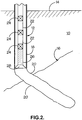
- Fig. 2 illustrates the same oil/gas well 10, but with extraction equipment partially introduced into the well in a "running-in” process, i.e. the process whereby extraction equipment is delivered to the oil/gas producing region of the well.
- This equipment comprises production tubing 22 which is located within the production casing 18 and which is formed of a series of tubing sections connected together by means of couplers 24 arranged to couple adjacent sections of tubing sections together.
- the extraction equipment further comprises a completion section 26 coupled to an end of the production tubing 22 and which is arranged, upon well completion, to reside in the portion of the well bore 18 (i.e. the openhole section 20) extending into the oil/gas bearing rock 16.
- the completion section 26 is arranged such that fluid can permeate from the surrounding oil/gas bearing rock into an interior section of the completion section 26 such that the fluid can be transferred to the surface 14 via the production tubing 22.
- the injected fluid is pumped from surface into the production tubing 22 and permeates through the completion section 26 into the reservoir rock 16.
- the illustrated embodiment of the completion arrangement of the invention includes a drill bit 28 coupled to an end of the completion section 26 remote from the end coupled to the production tubing 22.
- the drill bit 28 is located at the "front" face of the completion section 26, i.e. the face of the completion section 26 which is foremost with respect to its direction of travel into the openhole section 20.
- Fig. 3 illustrates the same oil/gas well 10 as Figs. 1 and 2 .
- the features illustrated in Fig. 3 which correspond to features already described in relation to Figs. 1 and 2 are denoted by like reference numerals.
- Fig. 3 differs from that of Fig. 2 in that the production tubing 22 extends further into the well bore 12.
- the completion section 26 and drill bit 28 are located within the production casing 18 of the lined section of the well bore 12.
- the completion section 26 and drill bit 28 have been inserted further so as to extend into the openhole section 20 of the well bore 12.
- the completion section 26 preferably comprises a number of different combinations of extraction devices, valves, sensors, measurements, mechanical and swellable packers etc.
- the completion section 26 is made up of openhole swellable packers 200 (for openhole compartmentalisation) and Inflow Control devices ("flow restrictors" 202) which serve two purposes: (i) during the "running in” procedure, drilling fluid 204 is pumped from surface down to the drill bit 28 (or ream-in shoe) to circulate and lubricate the completion section 26 during deployment; and (ii) during a production phase, hydrocarbons can enter the completion section 26 from reservoir rock surrounding the completion section 26, via the flow restrictors 202 and pass therefrom to the surface via production tubing 22 attached to the completion section 26.
- the flow restrictor 202 is formed with a plurality of nozzles 206 arranged to allow drilling fluid 204 to be injected through the production tubing 22 into a space 208 (which may be annular) around production tubing 22, this aids in a lubricating process to ease the passage of the completion section 26 into the well bore. Should the lubrication process fail, or be inadequate to remove debris, etc. and the completion section 26 becomes stuck, the completion section 26 can be rotated by means of surface control (or by a downhole mud motor - see Fig. 5 and the description relating thereto). However the rotational capability is secondary to the fact that drilling fluid is being flushed across the entire completion section 26, rather than merely at the drill bit 28.
- FIGS. 2 , 3 and 4 are merely schematic "snapshots" of the process of introducing extraction equipment into the well, and the progress of the extraction equipment on its route to the position as illustrated in Fig. 5 .
- FIG. 5 there is illustrated the same oil/gas well 10 as in Figs. 1 to 4 . Again, features corresponding to those already described are denoted by like reference numerals.
- the completion section 26 and drill bit 28 have reached total depth, i.e. the maximum extent to which the bore has previously been drilled. Once the completion section 26 and drill bit 28 have reached the total depth, the well 10 is effectively "complete” and an oil/gas extraction process can commence without limitation that might occur due to incomplete insertion of the production tubing and completion section.
- the drill bit 28 can be operated to, for example, remove "burrs" from the walls of the openhole section 20 and/or to remove debris from in front of the combined drill/completion section for transfer to, and removal at, the surface 14.
- such process is secondary to the main process of providing lubrication by way of drilling fluid 204 passing through nozzles 26 of the flow restrictors 200.
- the drill bit 28 is rotated by rotating the production tubing 22 at the surface 14 when the drill bit 28 has reached a pre-detemined depth (e.g. when it has entered the openhole section 20).
- a pre-detemined depth e.g. when it has entered the openhole section 20.
- FIG. 6 Another arrangement of the present invention is illustrated in Fig. 6 .
- the same well 10 as illustrated in the previous figures is shown and reference numerals for like features remain the same.
- a motor preferably a mud motor 30 as illustrated is provided between the completion section 26 and drill bit 28.
- the mud motor 30 is arranged to drive and control operation of the drill bit 28 and eliminates the requirement to rotate the production tubing 22 at surface 14 to operate the drill bit 28.
- the drill bit 28 and /or the motor 30 is intended to remain in place once its final depth has been reached.
- the mud motor 30 operates by means of fluid pumped from the surface through the production tubing 22 (denoted by arrows A). This fluid activates the mud motor 30 which, in turn, operates the drill bit 28.
- the drill bit 28 preferably comprises a number of nozzles 32 to allow the drilling fluid to exit a face of the drill bit 28. After the drilling fluid has exited through the nozzles 32, and through nozzles 206 in the flow restrictor 200, it can lubricate the drill bit 28 and carry the debris from the face of the drill bit 28 back through the space between the production tubing 22 and the walls of the openhole section 20 and between the production tubing 22 and the production casing 28 to the surface 14 (this is indicated by arrows B).
Landscapes
- Life Sciences & Earth Sciences (AREA)
- Engineering & Computer Science (AREA)
- Geology (AREA)
- Mining & Mineral Resources (AREA)
- Physics & Mathematics (AREA)
- Environmental & Geological Engineering (AREA)
- Fluid Mechanics (AREA)
- General Life Sciences & Earth Sciences (AREA)
- Geochemistry & Mineralogy (AREA)
- Earth Drilling (AREA)
Description
- The present invention relates to a completion arrangement and particularly, to a completion arrangement for a hydrocarbon (e.g. oil or gas) and/or an injection (e.g. water or gas) well.
- When an oil/gas well is drilled, extraction equipment is inserted into an oil/gas reservoir from which oil/gas will be produced to the surface. A bore is drilled into the oil/gas reservoir and production tubing is introduced into the bore. The oil/gas well has then to be "completed", which entails running a completion section into the well to enable extraction of hydrocarbons from the reservoir for transfer to the surface via the production tubing. It is generally desired that the completion section is ideally located at, or extends into, the bottom (or total depth) of the well.
- A number of "completion" devices exist, for example, "openhole completions", i.e. where a packer is provided on tubing above an "openhole" (an openhole being an uncased portion of a well bore), or "inflow control devices", i.e. a tubing section provided with devices to control flow of fluid from the reservoir to the interior of the tubing section in a producing well and control flow of fluid from the tubing section to the reservoir in an injection well.
- In current completion techniques, when the completion is "run-in" to the well, it is the weight of the completion string that urges the completion to the end of the well.
- However, such techniques are problematic in that the completion may get stuck due to entrained rock and debris accumulated at the head of the completion. Additionally, there may be "burrs" in the openhole section of the well caused by the drilling process, and the completion may also become stuck when it encounters these "burrs".
- Under the current techniques, if the completion becomes stuck as described above, then remedial actions (such as "jarring" the completion string) are taken to free the completion in an attempt to insert the completion section further into the well bore. Unfortunately, these remedial actions are not always successful, which leads to the well being completed as is or side-tracked. The problem of the completion becoming stuck is a particular problem in long horizontal wells.
-
WO 2008/043985 describes drilling a lower completion into a pre-drilled wellbore with casing liner. A casing liner is a tubular section that conventionally is 'pushed' into the pre-drilled hole to total depth. Once to total depth, the casing liner is cemented into place by pumping cement into the space between the reservoir rock and the casing liner (tubular section). The cement is required for structural integrity and to hold the casing liner in place. In order for hydrocarbons to reach the production tubing to flow to the surface, it is necessary that the casing liner be perforated using perforating charges to connect the production tubing space to the reservoir rock. -
GB 2416551 GB 2416551 -
WO 2005/042916 discloses a method of running a bore-lining tubing string into a bore which comprises running a tubing string, typically a liner string, into a bore while agitating the string. The agitation of the string reduces the friction between the string and the bore wall and thus facilitates the translation of the string into the bore. The agitation may also take place while the tubing is being cemented in the bore. Pressure pulses may be applied to fluid in the bore, which fluid may be cement slurry. -
EP 0713951 discloses a method and apparatus for drilling and completing a bore hole. Generally, the method comprises the steps of positioning a workstring in the well, with the workstring having attached thereto a bottom hole assembly. The bottom hole assembly may contain a bit for rotary drilling a bore hole; and, a drilling motor, operably associated with the bit, for rotating said drilling means. The method further includes the steps of circulating a fluid in the workstring so that the motor rotates the bit means; and, drilling the bore hole through a target reservoir. In one disclosed embodiment inEP 0713951 , the workstring string is a production string, and the production string is attached to an isolation safety valve member for isolating the well and the bore hole from pressure. -
EP 0697501 discloses an integrated drilling and evaluation system for drilling, logging and testing a well which comprises a drill string, a drill bit carried on a lower end of the drill string for drilling a well bore, logging while drilling means included in the drill string for identifying subsurface zones of formations of interest, packer means carried on the drill string above the drill bit for sealing a zone or formation of interest below the packer means, and a fluid testing means included in the drill string for controlling the flow of well fluid from the zone or formation of interest into the drill string. The system allows one or more subsurface zones or formations of interest in a well to be drilled, logged and tested without the necessity of removing the drill string from the well. -
WO 2007/094900 discloses a method of completing a well. The well may be a producing well or an injection well. In one embodiment disclosed inWO 2007/094900 , the method includes identifying technical issues associated with a well; selecting a technology to address each technical issue; defining criteria for each selected technology to determine when to deploy the selected technology in the well, wherein each selected technology remains dormant until the criteria are met; and integrating the technologies into a well completion profile stored in. memory and utilized in the deployment of the technologies into the well. The method provides the ability to proactively address technical issues to reduce workovers and interventions for a well. - The present invention seeks to provide for a completion arrangement having advantages over known such completions.
- According to an aspect of the present invention, there is provided a completion arrangement for a drilled hydrocarbon well bore comprising: a completion section arranged to be coupled to production tubing, and having means to allow hydrocarbons to pass therein from reservoir rock in which the well bore is formed, said means also arranged to serve as flushing portals, whereby drilling fluid introduced into said production tubing is arranged to flow via said means into a space between said production tubing and said well bore and circulate in said space; and impacting formations, operable by being drivingly moveable relative to the drilled well bore, wherein one, or both, of arranging said means to permit circulation of said drilling fluid in said space and operation of said impacting formations removes obstructing material from the drilled well bore, for return to surface by way of said space, during insertion of the completion arrangement into the well bore.
- An advantage of the present invention is that debris around the completion arrangement during an insertion process can be removed by: (i) flushing drilling fluid through said means which, during production, are arranged to allow hydrocarbons to pass into the production tubing from reservoir rock in which the well bore is formed, but which, during the insertion process, allow drilling fluid to enter a space around the production tubing; and (ii) driving the impacting formations. Thus, with the above two features, the completion section is less likely to become stuck when being "run-in" to the well.
- In this particular invention the lower completion can be set into the openhole section without cementing. Once the well is put into production, the hydrocarbon from the reservoir rock is drawn into the space created by the openhole packers. The hydrocarbon then flows from the space, through nozzles in the flow restrictors into the production tubing and then on to the surface. If this particular arrangement was to be cemented, then connection between the production tubing and the reservoir will be required via perforating charges. However, in the present invention, cementing is not required and the stability of the openhole section is maintained by the strength of the reservoir rock.
- As mentioned, cementing is not required for this invention since the type of lower completion serves a different purpose - this is an openhole completion with openhole packers and flow restrictors.
- The invention is further advantageous in that it enhances completion deployment and allows longer completions to be run, thereby providing completion capabilities for extended reach applications.
- The impacting formations are operable to crush, cut, abrade, scrape, pound or grind material and formations in the well bore.
- Also, said means to allow hydrocarbons to pass therein from reservoir rock in which the well bore is formed may comprise flow restrictors having at least one nozzle.
- Preferably, said impacting formations comprise a drill bit or ream-in shoe.
- Conveniently, said impacting formations are operable by rotating said production tubing, to which said impacting formations are coupled via said completion section.
- If required, the completion arrangement further comprises a motor coupled between said completion section and said impacting formations and arranged to control operation of said impacting formations.
- Further, said motor comprises a mud motor operable by means of drilling fluid supplied thereto through said production tubing and completion section.
- Preferably, said drilling fluid further serves to lubricate said impacting formations.
- According to another aspect of the present invention, there is provided production tubing for a hydrocarbon well, comprising a completion arrangement as described above.
- According to a further aspect of the present invention, there is provided a method of completing a drilled hydrocarbon well bore, comprising the steps of: inserting a completion arrangement into said drilled well bore, the completion arrangement comprising a completion section having means for allowing hydrocarbons to pass therein from reservoir rock in which the well bore is formed, said means also arranged to serve as flushing portals whereby drilling fluid introduced into the completion section via production tubing is arranged to flow via said means into a space between said completion arrangement and said well bore and circulate in said space ; and at least one of introducing drilling fluid into said completion arrangement for flow via said means into said space and/or driving said impacting formations so as to move relative to the drilled well bore to remove obstructing material from the drilled well bore during insertion of the completion arrangement into the well bore.
- Preferably, said driving step comprises rotating said production tubing to drive said impacting formations.
- If required, the method further comprises the step of: locating, between said completion section and said impacting formations, a motor; and wherein said driving step comprises activating said motor by means of fluid pumped to said motor via production tubing coupled to said completion section such that said motor can operate said impacting formations.
- The present invention is described further hereinafter, by way of example only, with reference to the accompanying drawings in which:
-
Fig. 1 illustrates a cross-sectional side view of an oil/gas well or an injection well; -
Fig. 2 illustrates a cross-sectional side view of the well ofFig. 1 into which the present invention is being introduced; -
Fig. 3 illustrates a cross-section side view of the well ofFig. 1 with the present invention located partially along the well length; -
Fig. 4 illustrates a cross-section side view of the well ofFig. 1 with a particular arrangement of the present invention located partially along the well length; -
Fig. 5 illustrates a cross-section side view of the well ofFig. 1 with the present invention located at total depth; and -
Fig. 6 illustrates a cross-section side view of the well ofFig. 1 with an alternative arrangement of the present invention being introduced to the well. - As mentioned,
Fig. 1 illustrates an oil/gas well or injection well 10. The well 10 comprises a well bore 12 which extends from thesurface 14 to oil/gas bearing rock 16. Part of the well bore 12 is lined with aproduction casing 18 to support the walls of the well bore 12 and prevent collapse of the well bore 12. The part of the well bore 12 which extends into the oil/gas bearing rock 16 comprises a so-calledopenhole section 20 which is not lined with production casing. -
Fig. 2 illustrates the same oil/gas well 10, but with extraction equipment partially introduced into the well in a "running-in" process, i.e. the process whereby extraction equipment is delivered to the oil/gas producing region of the well. This equipment comprisesproduction tubing 22 which is located within theproduction casing 18 and which is formed of a series of tubing sections connected together by means ofcouplers 24 arranged to couple adjacent sections of tubing sections together. The extraction equipment further comprises acompletion section 26 coupled to an end of theproduction tubing 22 and which is arranged, upon well completion, to reside in the portion of the well bore 18 (i.e. the openhole section 20) extending into the oil/gas bearing rock 16. Thecompletion section 26 is arranged such that fluid can permeate from the surrounding oil/gas bearing rock into an interior section of thecompletion section 26 such that the fluid can be transferred to thesurface 14 via theproduction tubing 22. Vice versa for an injection well: the injected fluid is pumped from surface into theproduction tubing 22 and permeates through thecompletion section 26 into thereservoir rock 16. - In addition to the
production tubing 22 and thecompletion section 26, the illustrated embodiment of the completion arrangement of the invention includes adrill bit 28 coupled to an end of thecompletion section 26 remote from the end coupled to theproduction tubing 22. Thedrill bit 28 is located at the "front" face of thecompletion section 26, i.e. the face of thecompletion section 26 which is foremost with respect to its direction of travel into theopenhole section 20. -
Fig. 3 illustrates the same oil/gas well 10 asFigs. 1 and2 . The features illustrated inFig. 3 which correspond to features already described in relation toFigs. 1 and2 are denoted by like reference numerals. - The illustration of
Fig. 3 differs from that ofFig. 2 in that theproduction tubing 22 extends further into the well bore 12. InFig. 2 , thecompletion section 26 anddrill bit 28 are located within theproduction casing 18 of the lined section of the well bore 12. However, inFig. 3 , thecompletion section 26 anddrill bit 28 have been inserted further so as to extend into theopenhole section 20 of the well bore 12. - The
completion section 26 preferably comprises a number of different combinations of extraction devices, valves, sensors, measurements, mechanical and swellable packers etc. In a particular arrangement as illustrated inFig. 4 , which shows a detailed view of thecompletion section 26 to illustrate the features thereof, thecompletion section 26 is made up of openhole swellable packers 200 (for openhole compartmentalisation) and Inflow Control devices ("flow restrictors" 202) which serve two purposes: (i) during the "running in" procedure, drilling fluid 204 is pumped from surface down to the drill bit 28 (or ream-in shoe) to circulate and lubricate thecompletion section 26 during deployment; and (ii) during a production phase, hydrocarbons can enter thecompletion section 26 from reservoir rock surrounding thecompletion section 26, via theflow restrictors 202 and pass therefrom to the surface viaproduction tubing 22 attached to thecompletion section 26. Since theflow restrictor 202 is formed with a plurality ofnozzles 206 arranged to allow drilling fluid 204 to be injected through theproduction tubing 22 into a space 208 (which may be annular) aroundproduction tubing 22, this aids in a lubricating process to ease the passage of thecompletion section 26 into the well bore. Should the lubrication process fail, or be inadequate to remove debris, etc. and thecompletion section 26 becomes stuck, thecompletion section 26 can be rotated by means of surface control (or by a downhole mud motor - seeFig. 5 and the description relating thereto). However the rotational capability is secondary to the fact that drilling fluid is being flushed across theentire completion section 26, rather than merely at thedrill bit 28. By efficiently flushing and lubricating across the entire lower completion, this may reduce the need to rotate thedrill bit 28. Debris is carried along thespace 208 to surface and since theflow restrictors 200 are passing fluid from theproduction tubing 22 into thespace 208, this aids in the flushing process. - The illustrations of
Figs. 2 ,3 and4 are merely schematic "snapshots" of the process of introducing extraction equipment into the well, and the progress of the extraction equipment on its route to the position as illustrated inFig. 5 . - Turning now to
Fig. 5 in detail, there is illustrated the same oil/gas well 10 as inFigs. 1 to 4 . Again, features corresponding to those already described are denoted by like reference numerals. - Here, the
completion section 26 anddrill bit 28 have reached total depth, i.e. the maximum extent to which the bore has previously been drilled. Once thecompletion section 26 anddrill bit 28 have reached the total depth, the well 10 is effectively "complete" and an oil/gas extraction process can commence without limitation that might occur due to incomplete insertion of the production tubing and completion section. - The lubrication process has been described above. Now the operation of the
drill bit 28 found in the illustrated embodiments of the invention will now be described in more detail. - As described above, in conventional processes where an oil/gas well is "completed", the extraction equipment (including a completion section) is introduced into the well bore, and it is the weight of the completion section and production tubing that urges the completion towards the end of the well (i.e. total depth) and pulls the production tubing behind it. However, and as mentioned above, the presence of "burrs" on the walls of the openhole section of the well which were introduced by the drilling process, or the accumulation of debris in front of the completion section, may cause the completion section to become stuck. Remedial actions (e.g. "jarring") are possible which can free the completion section for further insertion into the well bore, but these are not always effective and the well may therefore have to be completed without the completion section reaching total depth.
- By providing a
drill bit 28 at the head of thecompletion section 26, this allows thecompletion section 26 to be drilled, or rather reamed into position in the well bore should the lubrication process fail at some point to ease passage of the completion section into the well. Thus, in the illustrations ofFigs. 3 to 5 where thecompletion section 26 anddrill bit 28 are in theopenhole section 20 of the well bore 12, the drill bit can be operated to, for example, remove "burrs" from the walls of theopenhole section 20 and/or to remove debris from in front of the combined drill/completion section for transfer to, and removal at, thesurface 14. As noted above, such process is secondary to the main process of providing lubrication by way of drilling fluid 204 passing throughnozzles 26 of theflow restrictors 200. Thus, these features aid in the flushing process to carry debris to surface and to efficiently lubricate the space during deployment. - In a preferable arrangement, the
drill bit 28 is rotated by rotating theproduction tubing 22 at thesurface 14 when thedrill bit 28 has reached a pre-detemined depth (e.g. when it has entered the openhole section 20). By activating the drill bit, theopenhole section 20 is drilled/reamed and this allows thecompletion section 26 to reach total depth without becoming stuck. - Another arrangement of the present invention is illustrated in
Fig. 6 . Thesame well 10 as illustrated in the previous figures is shown and reference numerals for like features remain the same. However, in the arrangement ofFig. 6 , a motor (preferably amud motor 30 as illustrated) is provided between thecompletion section 26 anddrill bit 28. - The
mud motor 30 is arranged to drive and control operation of thedrill bit 28 and eliminates the requirement to rotate theproduction tubing 22 atsurface 14 to operate thedrill bit 28. - It should be appreciated that the
drill bit 28 and /or themotor 30 is intended to remain in place once its final depth has been reached. - The
mud motor 30 operates by means of fluid pumped from the surface through the production tubing 22 (denoted by arrows A). This fluid activates themud motor 30 which, in turn, operates thedrill bit 28. Thedrill bit 28 preferably comprises a number ofnozzles 32 to allow the drilling fluid to exit a face of thedrill bit 28. After the drilling fluid has exited through thenozzles 32, and throughnozzles 206 in theflow restrictor 200, it can lubricate thedrill bit 28 and carry the debris from the face of thedrill bit 28 back through the space between theproduction tubing 22 and the walls of theopenhole section 20 and between theproduction tubing 22 and theproduction casing 28 to the surface 14 (this is indicated by arrows B). - Advantages of the present invention have been described above although the present invention is particularly advantageous when used in the completion of horizontal wells.
Claims (13)
- A method of completing a drilled hydrocarbon well bore (12), comprising the steps of:inserting a completion arrangement into said drilled well bore (12), the completion arrangement comprising:a completion section (26) having means (202) for allowing hydrocarbons to pass therein from reservoir rock (16) in which the well bore (12) is formed, said means (202) also arranged to serve as flushing portals whereby drilling fluid introduced into the completion section (26) via production tubing (22) is arranged to flow via said means (202) into a space (208) between said completion arrangement and said well bore (12) and circulate in said space (208); andimpacting formations (28) coupled to an end of the completion section (26) ; andat least one of introducing drilling fluid into said completion arrangement for flow via said means (202) into said space (208) and driving said impacting formations (28) so as to move relative to the drilled well bore (12) to remove obstructing material from the drilled well bore (12) during insertion of the completion arrangement into the well bore.
- A method according to Claim 1, wherein said driving step comprises rotating said production tubing (22) to drive said impacting formations (28).
- A method according to Claim 1, further comprising the step of: locating a motor (30) between said completion section (26) and said impacting formations (28); wherein said driving step comprises activating said motor (30) by means of fluid pumped to said motor (30) via production tubing (22) coupled to said completion section (26) such that said motor (30) can operate said impacting formations (28).
- A method according to Claim 1, 2 or 3, comprising introducing drilling fluid into said completion arrangement for flow via said means (202) into said space (208) to remove obstructing material from the drilled well bore (12), and then permitting hydrocarbons to flow from said space (208) via said means (202) to be produced to surface (14) via production tubing (22).
- A method according to any preceding Claim, comprising both introducing drilling fluid into said completion arrangement for flow via said means (202) into said space (208) and driving said impacting formations (28) so as to move relative to the drilled well bore (12) to remove obstructing material from the drilled well bore (12) during insertion of the completion arrangement into the well bore (12).
- A method according to any preceding Claim, wherein the impacting formations (28) comprise a drill bit and/or a ream-in shoe.
- A completion arrangement for a drilled hydrocarbon well bore (12) comprising:a completion section (26) arranged to be coupled to production tubing (22) and having means (202) to allow hydrocarbons to pass therein from reservoir rock (16) in which the well bore (12) is formed, said means (202) also arranged to serve as flushing portals, whereby drilling fluid introduced into said production tubing (22) is arranged to flow via said means (202) into a space (208) between said production tubing (22) and said well bore (12) and circulate in said space (208); andimpacting formations (28) coupled to an end of the completion section (26) and being operable by being drivingly moveable relative to the drilled well bore (12),wherein one, or both, of arranging said means (202) to permit circulation of said drilling fluid in said space (208) and operation of said impacting formations (28) removes obstructing material from the drilled well bore (12), for return to surface (14) by way of said space (208), during insertion of the completion arrangement into the well bore (12).
- An arrangement according to Claim 7, wherein said means (202) to allow hydrocarbons to pass therein from reservoir rock (16) in which the well bore (12) is formed comprise flow restrictors (202) having at least one nozzle (206).
- An arrangement according to Claims 7 or 8, wherein said impacting formations comprise (28) a drill bit and/or a ream-in shoe.
- An arrangement according to any one or more of the preceding claims, wherein said impacting formations (28) are operable by rotating said production tubing (22), to which said impacting formations (28) are coupled via said completion section (26).
- An arrangement according to any one or more of the preceding claims, further comprising a motor (30) coupled between said completion section (26) and impacting formations (28) and arranged to control operation of said impacting formations (28).
- An arrangement according to Claim 11, wherein said motor (30) comprises a mud motor operable by means of drilling fluid supplied thereto through said production tubing (22) and completion section (26).
- An arrangement according to any one or more of the preceding claims, wherein said drilling fluid further serves to lubricate said impacting formations (28).
Applications Claiming Priority (2)
| Application Number | Priority Date | Filing Date | Title |
|---|---|---|---|
| GBGB0722995.8A GB0722995D0 (en) | 2007-11-23 | 2007-11-23 | Completion arrangement |
| PCT/GB2008/051035 WO2009066097A1 (en) | 2007-11-23 | 2008-11-06 | Completion arrangement |
Publications (2)
| Publication Number | Publication Date |
|---|---|
| EP2212518A1 EP2212518A1 (en) | 2010-08-04 |
| EP2212518B1 true EP2212518B1 (en) | 2017-01-04 |
Family
ID=38925946
Family Applications (1)
| Application Number | Title | Priority Date | Filing Date |
|---|---|---|---|
| EP08852389.9A Active EP2212518B1 (en) | 2007-11-23 | 2008-11-06 | Completion arrangement |
Country Status (6)
| Country | Link |
|---|---|
| US (1) | US20120222864A1 (en) |
| EP (1) | EP2212518B1 (en) |
| AU (1) | AU2008327734A1 (en) |
| CA (1) | CA2706712A1 (en) |
| GB (1) | GB0722995D0 (en) |
| WO (1) | WO2009066097A1 (en) |
Families Citing this family (9)
| Publication number | Priority date | Publication date | Assignee | Title |
|---|---|---|---|---|
| US7775284B2 (en) | 2007-09-28 | 2010-08-17 | Halliburton Energy Services, Inc. | Apparatus for adjustably controlling the inflow of production fluids from a subterranean well |
| US7857061B2 (en) | 2008-05-20 | 2010-12-28 | Halliburton Energy Services, Inc. | Flow control in a well bore |
| US8230935B2 (en) | 2009-10-09 | 2012-07-31 | Halliburton Energy Services, Inc. | Sand control screen assembly with flow control capability |
| GB0918358D0 (en) | 2009-10-20 | 2009-12-02 | Futuretec Ltd | Wellbore completion |
| US8256522B2 (en) | 2010-04-15 | 2012-09-04 | Halliburton Energy Services, Inc. | Sand control screen assembly having remotely disabled reverse flow control capability |
| US8403052B2 (en) | 2011-03-11 | 2013-03-26 | Halliburton Energy Services, Inc. | Flow control screen assembly having remotely disabled reverse flow control capability |
| US8485225B2 (en) | 2011-06-29 | 2013-07-16 | Halliburton Energy Services, Inc. | Flow control screen assembly having remotely disabled reverse flow control capability |
| CN107989572A (en) * | 2017-12-12 | 2018-05-04 | 天津大港油田石油工程研究院钻采技术开发有限公司 | A kind of Slim Hole Cementing sand control completion integrated pipe column and construction method |
| CN112177563A (en) * | 2019-07-01 | 2021-01-05 | 中国石油化工股份有限公司 | a well completion method |
Family Cites Families (7)
| Publication number | Priority date | Publication date | Assignee | Title |
|---|---|---|---|---|
| CA2155918C (en) * | 1994-08-15 | 2001-10-09 | Roger Lynn Schultz | Integrated well drilling and evaluation |
| US5842528A (en) * | 1994-11-22 | 1998-12-01 | Johnson; Michael H. | Method of drilling and completing wells |
| US7188687B2 (en) * | 1998-12-22 | 2007-03-13 | Weatherford/Lamb, Inc. | Downhole filter |
| US6729393B2 (en) * | 2000-03-30 | 2004-05-04 | Baker Hughes Incorporated | Zero drill completion and production system |
| GB0324744D0 (en) * | 2003-10-23 | 2003-11-26 | Andergauge Ltd | Running and cementing tubing |
| CN101375016B (en) * | 2006-02-10 | 2012-07-04 | 埃克森美孚上游研究公司 | Flexible Completions |
| US20080283238A1 (en) * | 2007-05-16 | 2008-11-20 | William Mark Richards | Apparatus for autonomously controlling the inflow of production fluids from a subterranean well |
-
2007
- 2007-11-23 GB GBGB0722995.8A patent/GB0722995D0/en not_active Ceased
-
2008
- 2008-11-06 CA CA2706712A patent/CA2706712A1/en not_active Abandoned
- 2008-11-06 US US12/744,462 patent/US20120222864A1/en not_active Abandoned
- 2008-11-06 WO PCT/GB2008/051035 patent/WO2009066097A1/en not_active Ceased
- 2008-11-06 EP EP08852389.9A patent/EP2212518B1/en active Active
- 2008-11-06 AU AU2008327734A patent/AU2008327734A1/en not_active Abandoned
Non-Patent Citations (1)
| Title |
|---|
| None * |
Also Published As
| Publication number | Publication date |
|---|---|
| CA2706712A1 (en) | 2009-05-28 |
| US20120222864A1 (en) | 2012-09-06 |
| AU2008327734A1 (en) | 2009-05-28 |
| GB0722995D0 (en) | 2008-01-02 |
| EP2212518A1 (en) | 2010-08-04 |
| WO2009066097A1 (en) | 2009-05-28 |
Similar Documents
| Publication | Publication Date | Title |
|---|---|---|
| US8596386B2 (en) | System and method for drilling and completing lateral boreholes | |
| RU2390623C2 (en) | Single-trip downhole device equipped with means of minimising sand ingress | |
| US8813844B2 (en) | System and method for drilling lateral boreholes | |
| US20120222864A1 (en) | Completion arrangement | |
| US6223823B1 (en) | Method of and apparatus for installing casing in a well | |
| CA2514534C (en) | A downhole tool with an axial drive unit | |
| US7422059B2 (en) | Fluid injection stimulated heavy oil or mineral production system | |
| CA2511249C (en) | Method for drilling a lateral wellbore with secondary fluid injection | |
| US20080202755A1 (en) | One trip system for circulating, perforating and treating | |
| US20080185150A1 (en) | Apparatus and Method for Cleaning a Well | |
| JP2011508125A (en) | Method and apparatus for programmable pressure drilling and programmable gradient drilling and finishing | |
| NO333920B1 (en) | Apparatus and method for filtering fluid as well as method for expanding an expandable filter in a wellbore | |
| EP2483510A2 (en) | Remotely controlled apparatus for downhole applications and methods of operation | |
| AU2006306375B2 (en) | Fracking multiple casing exit laterals | |
| DK2935771T3 (en) | METHOD AND DEVICE FOR TREATING AN UNDERGROUND AREA | |
| EA025346B1 (en) | Method for combined cleaning and plugging in a well | |
| NO349432B1 (en) | Method and system for abandoning a cased borehole | |
| US5220829A (en) | Downhole formation pump | |
| WO2014137914A1 (en) | Liner top cleaning method prior to bha removal in drilling with advancing liner systems | |
| US11047196B2 (en) | Production tubing conversion device and methods of use | |
| US12371967B2 (en) | Wellbore operations system and method | |
| US11131159B1 (en) | Casing exit anchor with redundant setting system | |
| US20230125952A1 (en) | Electrically actuated tubular cleaning system | |
| EP3310991A1 (en) | Redressing method and redressed completion system |
Legal Events
| Date | Code | Title | Description |
|---|---|---|---|
| PUAI | Public reference made under article 153(3) epc to a published international application that has entered the european phase |
Free format text: ORIGINAL CODE: 0009012 |
|
| 17P | Request for examination filed |
Effective date: 20100525 |
|
| AK | Designated contracting states |
Kind code of ref document: A1 Designated state(s): AT BE BG CH CY CZ DE DK EE ES FI FR GB GR HR HU IE IS IT LI LT LU LV MC MT NL NO PL PT RO SE SI SK TR |
|
| AX | Request for extension of the european patent |
Extension state: AL BA MK RS |
|
| 17Q | First examination report despatched |
Effective date: 20101115 |
|
| DAX | Request for extension of the european patent (deleted) | ||
| GRAP | Despatch of communication of intention to grant a patent |
Free format text: ORIGINAL CODE: EPIDOSNIGR1 |
|
| INTG | Intention to grant announced |
Effective date: 20160729 |
|
| RAP1 | Party data changed (applicant data changed or rights of an application transferred) |
Owner name: SWELLFIX UK LIMITED |
|
| STAA | Information on the status of an ep patent application or granted ep patent |
Free format text: STATUS: GRANT OF PATENT IS INTENDED |
|
| GRAS | Grant fee paid |
Free format text: ORIGINAL CODE: EPIDOSNIGR3 |
|
| GRAA | (expected) grant |
Free format text: ORIGINAL CODE: 0009210 |
|
| STAA | Information on the status of an ep patent application or granted ep patent |
Free format text: STATUS: THE PATENT HAS BEEN GRANTED |
|
| AK | Designated contracting states |
Kind code of ref document: B1 Designated state(s): AT BE BG CH CY CZ DE DK EE ES FI FR GB GR HR HU IE IS IT LI LT LU LV MC MT NL NO PL PT RO SE SI SK TR |
|
| REG | Reference to a national code |
Ref country code: GB Ref legal event code: FG4D |
|
| REG | Reference to a national code |
Ref country code: CH Ref legal event code: EP |
|
| REG | Reference to a national code |
Ref country code: AT Ref legal event code: REF Ref document number: 859437 Country of ref document: AT Kind code of ref document: T Effective date: 20170115 |
|
| REG | Reference to a national code |
Ref country code: IE Ref legal event code: FG4D |
|
| REG | Reference to a national code |
Ref country code: DE Ref legal event code: R096 Ref document number: 602008048284 Country of ref document: DE |
|
| REG | Reference to a national code |
Ref country code: LT Ref legal event code: MG4D Ref country code: NL Ref legal event code: MP Effective date: 20170104 |
|
| REG | Reference to a national code |
Ref country code: AT Ref legal event code: MK05 Ref document number: 859437 Country of ref document: AT Kind code of ref document: T Effective date: 20170104 |
|
| PG25 | Lapsed in a contracting state [announced via postgrant information from national office to epo] |
Ref country code: NL Free format text: LAPSE BECAUSE OF FAILURE TO SUBMIT A TRANSLATION OF THE DESCRIPTION OR TO PAY THE FEE WITHIN THE PRESCRIBED TIME-LIMIT Effective date: 20170104 |
|
| PG25 | Lapsed in a contracting state [announced via postgrant information from national office to epo] |
Ref country code: NO Free format text: LAPSE BECAUSE OF FAILURE TO SUBMIT A TRANSLATION OF THE DESCRIPTION OR TO PAY THE FEE WITHIN THE PRESCRIBED TIME-LIMIT Effective date: 20170404 Ref country code: LT Free format text: LAPSE BECAUSE OF FAILURE TO SUBMIT A TRANSLATION OF THE DESCRIPTION OR TO PAY THE FEE WITHIN THE PRESCRIBED TIME-LIMIT Effective date: 20170104 Ref country code: GR Free format text: LAPSE BECAUSE OF FAILURE TO SUBMIT A TRANSLATION OF THE DESCRIPTION OR TO PAY THE FEE WITHIN THE PRESCRIBED TIME-LIMIT Effective date: 20170405 Ref country code: HR Free format text: LAPSE BECAUSE OF FAILURE TO SUBMIT A TRANSLATION OF THE DESCRIPTION OR TO PAY THE FEE WITHIN THE PRESCRIBED TIME-LIMIT Effective date: 20170104 Ref country code: IS Free format text: LAPSE BECAUSE OF FAILURE TO SUBMIT A TRANSLATION OF THE DESCRIPTION OR TO PAY THE FEE WITHIN THE PRESCRIBED TIME-LIMIT Effective date: 20170504 Ref country code: FI Free format text: LAPSE BECAUSE OF FAILURE TO SUBMIT A TRANSLATION OF THE DESCRIPTION OR TO PAY THE FEE WITHIN THE PRESCRIBED TIME-LIMIT Effective date: 20170104 |
|
| PG25 | Lapsed in a contracting state [announced via postgrant information from national office to epo] |
Ref country code: SE Free format text: LAPSE BECAUSE OF FAILURE TO SUBMIT A TRANSLATION OF THE DESCRIPTION OR TO PAY THE FEE WITHIN THE PRESCRIBED TIME-LIMIT Effective date: 20170104 Ref country code: PL Free format text: LAPSE BECAUSE OF FAILURE TO SUBMIT A TRANSLATION OF THE DESCRIPTION OR TO PAY THE FEE WITHIN THE PRESCRIBED TIME-LIMIT Effective date: 20170104 Ref country code: PT Free format text: LAPSE BECAUSE OF FAILURE TO SUBMIT A TRANSLATION OF THE DESCRIPTION OR TO PAY THE FEE WITHIN THE PRESCRIBED TIME-LIMIT Effective date: 20170504 Ref country code: AT Free format text: LAPSE BECAUSE OF FAILURE TO SUBMIT A TRANSLATION OF THE DESCRIPTION OR TO PAY THE FEE WITHIN THE PRESCRIBED TIME-LIMIT Effective date: 20170104 Ref country code: BG Free format text: LAPSE BECAUSE OF FAILURE TO SUBMIT A TRANSLATION OF THE DESCRIPTION OR TO PAY THE FEE WITHIN THE PRESCRIBED TIME-LIMIT Effective date: 20170404 Ref country code: ES Free format text: LAPSE BECAUSE OF FAILURE TO SUBMIT A TRANSLATION OF THE DESCRIPTION OR TO PAY THE FEE WITHIN THE PRESCRIBED TIME-LIMIT Effective date: 20170104 Ref country code: LV Free format text: LAPSE BECAUSE OF FAILURE TO SUBMIT A TRANSLATION OF THE DESCRIPTION OR TO PAY THE FEE WITHIN THE PRESCRIBED TIME-LIMIT Effective date: 20170104 |
|
| REG | Reference to a national code |
Ref country code: DE Ref legal event code: R097 Ref document number: 602008048284 Country of ref document: DE |
|
| PG25 | Lapsed in a contracting state [announced via postgrant information from national office to epo] |
Ref country code: IT Free format text: LAPSE BECAUSE OF FAILURE TO SUBMIT A TRANSLATION OF THE DESCRIPTION OR TO PAY THE FEE WITHIN THE PRESCRIBED TIME-LIMIT Effective date: 20170104 Ref country code: EE Free format text: LAPSE BECAUSE OF FAILURE TO SUBMIT A TRANSLATION OF THE DESCRIPTION OR TO PAY THE FEE WITHIN THE PRESCRIBED TIME-LIMIT Effective date: 20170104 Ref country code: SK Free format text: LAPSE BECAUSE OF FAILURE TO SUBMIT A TRANSLATION OF THE DESCRIPTION OR TO PAY THE FEE WITHIN THE PRESCRIBED TIME-LIMIT Effective date: 20170104 Ref country code: RO Free format text: LAPSE BECAUSE OF FAILURE TO SUBMIT A TRANSLATION OF THE DESCRIPTION OR TO PAY THE FEE WITHIN THE PRESCRIBED TIME-LIMIT Effective date: 20170104 Ref country code: CZ Free format text: LAPSE BECAUSE OF FAILURE TO SUBMIT A TRANSLATION OF THE DESCRIPTION OR TO PAY THE FEE WITHIN THE PRESCRIBED TIME-LIMIT Effective date: 20170104 |
|
| PLBE | No opposition filed within time limit |
Free format text: ORIGINAL CODE: 0009261 |
|
| STAA | Information on the status of an ep patent application or granted ep patent |
Free format text: STATUS: NO OPPOSITION FILED WITHIN TIME LIMIT |
|
| PG25 | Lapsed in a contracting state [announced via postgrant information from national office to epo] |
Ref country code: DK Free format text: LAPSE BECAUSE OF FAILURE TO SUBMIT A TRANSLATION OF THE DESCRIPTION OR TO PAY THE FEE WITHIN THE PRESCRIBED TIME-LIMIT Effective date: 20170104 |
|
| 26N | No opposition filed |
Effective date: 20171005 |
|
| PG25 | Lapsed in a contracting state [announced via postgrant information from national office to epo] |
Ref country code: SI Free format text: LAPSE BECAUSE OF FAILURE TO SUBMIT A TRANSLATION OF THE DESCRIPTION OR TO PAY THE FEE WITHIN THE PRESCRIBED TIME-LIMIT Effective date: 20170104 |
|
| REG | Reference to a national code |
Ref country code: DE Ref legal event code: R119 Ref document number: 602008048284 Country of ref document: DE |
|
| PG25 | Lapsed in a contracting state [announced via postgrant information from national office to epo] |
Ref country code: MC Free format text: LAPSE BECAUSE OF FAILURE TO SUBMIT A TRANSLATION OF THE DESCRIPTION OR TO PAY THE FEE WITHIN THE PRESCRIBED TIME-LIMIT Effective date: 20170104 |
|
| PG25 | Lapsed in a contracting state [announced via postgrant information from national office to epo] |
Ref country code: LI Free format text: LAPSE BECAUSE OF NON-PAYMENT OF DUE FEES Effective date: 20171130 Ref country code: CH Free format text: LAPSE BECAUSE OF NON-PAYMENT OF DUE FEES Effective date: 20171130 |
|
| PG25 | Lapsed in a contracting state [announced via postgrant information from national office to epo] |
Ref country code: LU Free format text: LAPSE BECAUSE OF NON-PAYMENT OF DUE FEES Effective date: 20171106 |
|
| REG | Reference to a national code |
Ref country code: FR Ref legal event code: ST Effective date: 20180731 Ref country code: BE Ref legal event code: MM Effective date: 20171130 |
|
| REG | Reference to a national code |
Ref country code: IE Ref legal event code: MM4A |
|
| PG25 | Lapsed in a contracting state [announced via postgrant information from national office to epo] |
Ref country code: MT Free format text: LAPSE BECAUSE OF NON-PAYMENT OF DUE FEES Effective date: 20171106 |
|
| PG25 | Lapsed in a contracting state [announced via postgrant information from national office to epo] |
Ref country code: DE Free format text: LAPSE BECAUSE OF NON-PAYMENT OF DUE FEES Effective date: 20180602 Ref country code: FR Free format text: LAPSE BECAUSE OF NON-PAYMENT OF DUE FEES Effective date: 20171130 Ref country code: IE Free format text: LAPSE BECAUSE OF NON-PAYMENT OF DUE FEES Effective date: 20171106 |
|
| PG25 | Lapsed in a contracting state [announced via postgrant information from national office to epo] |
Ref country code: BE Free format text: LAPSE BECAUSE OF NON-PAYMENT OF DUE FEES Effective date: 20171130 |
|
| PG25 | Lapsed in a contracting state [announced via postgrant information from national office to epo] |
Ref country code: HU Free format text: LAPSE BECAUSE OF FAILURE TO SUBMIT A TRANSLATION OF THE DESCRIPTION OR TO PAY THE FEE WITHIN THE PRESCRIBED TIME-LIMIT; INVALID AB INITIO Effective date: 20081106 |
|
| PG25 | Lapsed in a contracting state [announced via postgrant information from national office to epo] |
Ref country code: CY Free format text: LAPSE BECAUSE OF NON-PAYMENT OF DUE FEES Effective date: 20170104 |
|
| PG25 | Lapsed in a contracting state [announced via postgrant information from national office to epo] |
Ref country code: TR Free format text: LAPSE BECAUSE OF FAILURE TO SUBMIT A TRANSLATION OF THE DESCRIPTION OR TO PAY THE FEE WITHIN THE PRESCRIBED TIME-LIMIT Effective date: 20170104 |
|
| PGFP | Annual fee paid to national office [announced via postgrant information from national office to epo] |
Ref country code: GB Payment date: 20251125 Year of fee payment: 18 |