EP2212054B1 - Method of joining a header to a series of tubular members for a heat exchanger - Google Patents
Method of joining a header to a series of tubular members for a heat exchanger Download PDFInfo
- Publication number
- EP2212054B1 EP2212054B1 EP08845196.8A EP08845196A EP2212054B1 EP 2212054 B1 EP2212054 B1 EP 2212054B1 EP 08845196 A EP08845196 A EP 08845196A EP 2212054 B1 EP2212054 B1 EP 2212054B1
- Authority
- EP
- European Patent Office
- Prior art keywords
- header
- tubular members
- series
- tube
- alloy
- Prior art date
- Legal status (The legal status is an assumption and is not a legal conclusion. Google has not performed a legal analysis and makes no representation as to the accuracy of the status listed.)
- Active
Links
Images


Classifications
-
- B—PERFORMING OPERATIONS; TRANSPORTING
- B23—MACHINE TOOLS; METAL-WORKING NOT OTHERWISE PROVIDED FOR
- B23P—METAL-WORKING NOT OTHERWISE PROVIDED FOR; COMBINED OPERATIONS; UNIVERSAL MACHINE TOOLS
- B23P15/00—Making specific metal objects by operations not covered by a single other subclass or a group in this subclass
- B23P15/26—Making specific metal objects by operations not covered by a single other subclass or a group in this subclass heat exchangers or the like
-
- B—PERFORMING OPERATIONS; TRANSPORTING
- B21—MECHANICAL METAL-WORKING WITHOUT ESSENTIALLY REMOVING MATERIAL; PUNCHING METAL
- B21D—WORKING OR PROCESSING OF SHEET METAL OR METAL TUBES, RODS OR PROFILES WITHOUT ESSENTIALLY REMOVING MATERIAL; PUNCHING METAL
- B21D39/00—Application of procedures in order to connect objects or parts, e.g. coating with sheet metal otherwise than by plating; Tube expanders
- B21D39/06—Application of procedures in order to connect objects or parts, e.g. coating with sheet metal otherwise than by plating; Tube expanders of tubes in openings, e.g. rolling-in
-
- B—PERFORMING OPERATIONS; TRANSPORTING
- B21—MECHANICAL METAL-WORKING WITHOUT ESSENTIALLY REMOVING MATERIAL; PUNCHING METAL
- B21D—WORKING OR PROCESSING OF SHEET METAL OR METAL TUBES, RODS OR PROFILES WITHOUT ESSENTIALLY REMOVING MATERIAL; PUNCHING METAL
- B21D53/00—Making other particular articles
- B21D53/02—Making other particular articles heat exchangers or parts thereof, e.g. radiators, condensers fins, headers
- B21D53/06—Making other particular articles heat exchangers or parts thereof, e.g. radiators, condensers fins, headers of metal tubes
-
- B—PERFORMING OPERATIONS; TRANSPORTING
- B21—MECHANICAL METAL-WORKING WITHOUT ESSENTIALLY REMOVING MATERIAL; PUNCHING METAL
- B21D—WORKING OR PROCESSING OF SHEET METAL OR METAL TUBES, RODS OR PROFILES WITHOUT ESSENTIALLY REMOVING MATERIAL; PUNCHING METAL
- B21D53/00—Making other particular articles
- B21D53/02—Making other particular articles heat exchangers or parts thereof, e.g. radiators, condensers fins, headers
- B21D53/08—Making other particular articles heat exchangers or parts thereof, e.g. radiators, condensers fins, headers of both metal tubes and sheet metal
-
- F—MECHANICAL ENGINEERING; LIGHTING; HEATING; WEAPONS; BLASTING
- F02—COMBUSTION ENGINES; HOT-GAS OR COMBUSTION-PRODUCT ENGINE PLANTS
- F02B—INTERNAL-COMBUSTION PISTON ENGINES; COMBUSTION ENGINES IN GENERAL
- F02B29/00—Engines characterised by provision for charging or scavenging not provided for in groups F02B25/00, F02B27/00 or F02B33/00 - F02B39/00; Details thereof
- F02B29/04—Cooling of air intake supply
- F02B29/0406—Layout of the intake air cooling or coolant circuit
- F02B29/0425—Air cooled heat exchangers
- F02B29/0431—Details or means to guide the ambient air to the heat exchanger, e.g. having a fan, flaps, a bypass or a special location in the engine compartment
-
- F—MECHANICAL ENGINEERING; LIGHTING; HEATING; WEAPONS; BLASTING
- F28—HEAT EXCHANGE IN GENERAL
- F28F—DETAILS OF HEAT-EXCHANGE AND HEAT-TRANSFER APPARATUS, OF GENERAL APPLICATION
- F28F21/00—Constructions of heat-exchange apparatus characterised by the selection of particular materials
- F28F21/08—Constructions of heat-exchange apparatus characterised by the selection of particular materials of metal
-
- F—MECHANICAL ENGINEERING; LIGHTING; HEATING; WEAPONS; BLASTING
- F28—HEAT EXCHANGE IN GENERAL
- F28F—DETAILS OF HEAT-EXCHANGE AND HEAT-TRANSFER APPARATUS, OF GENERAL APPLICATION
- F28F9/00—Casings; Header boxes; Auxiliary supports for elements; Auxiliary members within casings
- F28F9/02—Header boxes; End plates
- F28F9/04—Arrangements for sealing elements into header boxes or end plates
- F28F9/16—Arrangements for sealing elements into header boxes or end plates by permanent joints, e.g. by rolling
-
- F—MECHANICAL ENGINEERING; LIGHTING; HEATING; WEAPONS; BLASTING
- F28—HEAT EXCHANGE IN GENERAL
- F28F—DETAILS OF HEAT-EXCHANGE AND HEAT-TRANSFER APPARATUS, OF GENERAL APPLICATION
- F28F2265/00—Safety or protection arrangements; Arrangements for preventing malfunction
- F28F2265/26—Safety or protection arrangements; Arrangements for preventing malfunction for allowing differential expansion between elements
-
- Y—GENERAL TAGGING OF NEW TECHNOLOGICAL DEVELOPMENTS; GENERAL TAGGING OF CROSS-SECTIONAL TECHNOLOGIES SPANNING OVER SEVERAL SECTIONS OF THE IPC; TECHNICAL SUBJECTS COVERED BY FORMER USPC CROSS-REFERENCE ART COLLECTIONS [XRACs] AND DIGESTS
- Y02—TECHNOLOGIES OR APPLICATIONS FOR MITIGATION OR ADAPTATION AGAINST CLIMATE CHANGE
- Y02T—CLIMATE CHANGE MITIGATION TECHNOLOGIES RELATED TO TRANSPORTATION
- Y02T10/00—Road transport of goods or passengers
- Y02T10/10—Internal combustion engine [ICE] based vehicles
- Y02T10/12—Improving ICE efficiencies
-
- Y—GENERAL TAGGING OF NEW TECHNOLOGICAL DEVELOPMENTS; GENERAL TAGGING OF CROSS-SECTIONAL TECHNOLOGIES SPANNING OVER SEVERAL SECTIONS OF THE IPC; TECHNICAL SUBJECTS COVERED BY FORMER USPC CROSS-REFERENCE ART COLLECTIONS [XRACs] AND DIGESTS
- Y10—TECHNICAL SUBJECTS COVERED BY FORMER USPC
- Y10T—TECHNICAL SUBJECTS COVERED BY FORMER US CLASSIFICATION
- Y10T29/00—Metal working
- Y10T29/49—Method of mechanical manufacture
- Y10T29/4935—Heat exchanger or boiler making
- Y10T29/49373—Tube joint and tube plate structure
- Y10T29/49375—Tube joint and tube plate structure including conduit expansion or inflation
Definitions
- This application relates in general to a heat exchanger and, more particularly, to a header for mechanically joining with a series of tubes in the formation of an air-to-air after-cooler or an exhaust gas recirculation cooler, wherein leakage at the tube/header joint is reduced.
- Document US2004040698 discloses a method of securing a plurality of oblong tubes into a plurality of circular openings in a header of a CT or Serpentine style fin core exchanger. One end of each tube is shaped into a circle, inserted into a circular opening in the header and bonded into place thus forming a Flat-Round joint.
- the tubes i.e., brass or copper alloys
- the headers i.e., carbon steel
- these materials have different thermal expansion coefficients.
- the different thermal expansion coefficients of the two materials cause a significant amount of stress to be applied to the tube material.
- the brass or copper alloy tube has a tendency to grow diametrically about 1.75 times what the carbon steel header hole wants to expand.
- a bonding agent or metal filler material such as a brazing alloy
- a bonding agent or metal filler material such as a brazing alloy
- a preferred technique for attaching tubes to a header is a technique known as a CUPROBRAZETM technique.
- CUPROBRAZETM is a manufacturing process that is used to braze copper and brass at temperatures that are generally lower than normal brazing operations, but do not exceed the softening temperatures of the components being joined. This process involves depositing a braze paste on the tubes, which are then assembled and heated to a suitable brazing temperature.
- the tubes used in the CUPROBRAZETM process are based on the copper zinc iron (CuZnFe) system; particularly an alloy containing 14-31% by weight zinc, 0.7-1.5% by weight iron, 0.001-0.050% by weight phosphorous and 0-0.09% by weight arsenic, the balance being copper and incidental impurities.
- the paste used as the brazing compound is known as OKC 600, as discussed in U.S. Patent No. 5,378,294 to Rissanen and U.S. Patent Nos. 5,429,794 and 6,264,764 to Kamf et al.
- This compound contains binders and a metal braze alloy based on the CuSnP system, for example, about 75% copper, about 15% tin, about 5% nickel and about 5% phosphorus.
- Other compounds and methods are being developed for use with the CUPROBRAZETM technique. These compounds are the subject of U.S. Patent Nos. 7,032,808 and 6,997,371 to Shabtay and U.S. Patent Application Publication Nos. 2005/0283967 and 2006/0249559 to Panthofer . In a typical CUPROBAZETM process, a thin gauge brass header is used.
- the header is less than approximately 1 ⁇ 4" thick to enable the oval holes to be punched therethrough and/or extruded so as to produce a collar.
- the tubes are then inserted through these collared holes and brazed into this header with the brazing paste.
- Other alloys currently in use to bond brass and copper to plain carbon steel generally have some kind of high level of silver content. Consequently, their use becomes price prohibitive. Also, the application of these materials would add labor costs and additional steps to the manufacturing process. Furthermore, these filler materials can also crack in high stress applications causing leaks to occur that are larger than those seen in the mechanical bonded joints.
- the present invention is directed to a process of mechanically joining a header to a series of tubular members for a heat exchanger utilizing a header material having thermal expansion properties similar to the material used for the series of tubes, resulting in the reduction and/or elimination of leakage at the tube/header joint that can occur as a result of high temperature exposure of the heat exchanger assembly. Further, the present invention provides a heat exchanger assembly and a process of forming the heat exchanger assembly wherein the reduction and/or elimination of leakage at the tube/header joint of the mechanically joined members is achieved in a cost-effective manner without the use of a bonding or filling agent.
- Figs. 1-2 show partial end views of a tube/header assembly, generally indicated as 10, 20, for a heat exchanger, such as an air-to-air after-cooler assembly, wherein the series of tubes is laid out according to various arrangements.
- the process of the present invention can be used with any type of fin and tube arrangement. These arrangements include, but are not limited to, staggered, parallel, canted, plate fin, Serpentine, CT, and the like.
- the process of the present invention can also be used with other types of heat exchangers, such as exhaust gas recirculation coolers.
- the tubular members 12 are positioned perpendicular to each other and inserted into openings 22 in a header 30.
- the tubular members 12 are positioned in a staggered array and inserted into openings 22 in the header 30.
- the staggered array arrangement of Fig. 2 provides less tube side pressure drop as the core includes more tubes in the same volume of core as the core arrangement of Fig. 1 , given that the web or minimum distance between the header holes remains the same.
- the tubular members 12 are attached to the header 30 by a mechanical attachment wherein the individual tubular members 12 are mechanically expanded, rolled or swaged into the openings 22 of the header 30 having similar hole geometry to provide the tube-to-header connection.
- This expansion technique for constructing a heat exchanger is discussed in detail in U.S. Patent No. 3,857,151 to Young et al. and shown in Figs. 5A-5D .
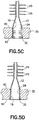
- a tube 16 which has been preliminarily cold-worked to form a rounded end and is positioned within a similarly shaped hole 22 having an inner surface 24 located in a header 30. The tube end 16 is then internally expanded.
- FIG. 5C shows the lines of force on the inside of the tube due to an expanding tool which is rotatable in the rounded end 16 of the tubular members 12 as it is pressed into the rounded section.
- the end of the tube 16 is caused to literally flow into tight contact with the inner surface 24 of the hole 22 to mechanically join the tubular members 12 to the header 30.
- a series of serrations or threads 32 can be formed along the inner surface 24 of the hole 22 to aid in the mechanical integration of the tube end 16 within the hole 22.
- the present invention utilizes a header 30 formed from a material having thermal expansion properties similar to the material used for the series of tubular members 12. It has been found that this allows one to reduce and/or eliminate leakage at a tube/header joint 32 of mechanically joined members in a cost-effective manner.
- the present invention is directed to a heat exchanger, such as an air-to-air after-cooler assembly 10, 20 comprising a series of tubular members 12 formed from a first metal, each of the tubular members 12 including an end portion and a header 30 formed from a second metal, wherein the first metal and the second metal have similar coefficients of thermal expansions.
- the header 30 includes a plurality of openings 22 extending therethrough and each of the end portions of the tubular members 12 is mechanically secured within corresponding openings within the header 30 to form the after-cooler assembly 10, 20.
- the present invention is directed to a method of joining the header 30 to the series of tubular members 12 for an air-to-air after-cooler assembly 10, 20 wherein a series of generally flat or oval tubular members 12 formed from a first metal is provided.
- the flat or oval portions of the tubular members 12 extend through the main core of the assembly.
- the flat or oval portions of the tubular members 12 can extend through plate fins 15 of the heat exchanger.
- Other core arrangements suitable for use in the invention include fins having a Serpentine, lanced/offset, square wave, or any other commonly used design. As shown in Figs. 3A-3B, 4A-4B , and 5A-5D at least one end portion 16 of each of the tubular members 12 is transformed into a generally round shape.
- a header 30 formed from a second metal is provided in which the header includes a plurality of openings 22 extending therethrough, wherein the first metal and the second metal have similar coefficients of thermal expansions.
- Each of the rounded end portions 16 of the tubular members 12 is inserted within a corresponding opening 22 within the header 30 to form the after-cooler assembly 10, 20.
- the rounded end portions of the tubular members 12 are mechanically expanded to bring these end portions 16 into contact with, and to join the end portions of the tubular member 12 within the openings 22 of the header.
- the present invention seeks to use a material formed of a second metal material for the header 30 wherein this second metal material has significantly closer thermal expansion properties to the first metal material of the tubular members 12.
- the header 30 is generally a flat or planar sheet of material having a thickness of at least 1 ⁇ 4", typically a thickness of between 1 ⁇ 4"-1".
- the header 30 of the present invention is thick enough to support the mechanical bond between the circular end of the tubular members 12 and the header 30. This thicker header 30 reduces the deformation of the header 30 when the tube-to-header assembly is in use.
- the added strength provided by the thicker header 30 allows longer tubes to be used than in the prior art type tube-to-header assemblies, thereby increasing the heat exchange capability of, for example, a heat exchanger.
- the header 30 has a thickness that is thick enough to support the tubular members 12, such that the ends 16 of the tubular members 12 enter through a first side 40 of the header, extend through the openings 20, and are flush with a second side 42 of the header 30.
- the header 30 generally does not have collars extending from, or punched through, thin gauge (i.e., less than 1 ⁇ 4") headers such as typically used in the CUPROBRAZETM process.
- the preferred header material comprises a stainless steel, but is not necessarily limited to any particular grade as any one of the varieties of stainless steel that gives a significant increase in thermal expansion as compared to plain carbon steel could be used.
- a significant increase can be defined as a reduction in the difference between thermal expansions of the brass tubular members 12 and the header 30 by at least 25%.
- the stainless steel that is used according to the invention is stainless steel 304 or 304L.
- a larger reduction in the difference of thermal expansion rates should equate to a more solid joint 34 and reduction in leaks. With higher temperatures, a closer approach between the tubular members 12 and header 30 thermal expansion rates will be required and header material choice will need to be altered to achieve this. Header material choice will also be determined by other factors such as the desire to use the stainless steel material for its welding properties.
- the first metal material of the tubular members 12 typically comprises a brass or copper alloy material and/or a CUPROBRAZETM (CuZnFe) brass material, as discussed in detail above.
- a CuZnFe alloy is much harder than the tube materials previously used and thus requires special processing and forming.
- the material of the tubular members is an alloy of CuZnFe, wherein the alloy comprises 14-31% by weight zinc, 0.7-1.5% by weight iron, 0.001-0.050% by weight phosphorous and 0-0.09% by weight arsenic, and a balance of the alloy being copper and incidental impurities.
- prior tube materials such as red brass, typically had a Vickers hardness of 80-95 in its raw form.
- Vickers hardness for the CuZnFe alloy is approximately 130 in its raw form.
- Both materials are made on a tube mill by forming a flat strip into the oval shape and then using high frequency induction coils to weld the edges of the strip together. This welding process causes a weld bead to form on the inside and outside of the main tube wall.
- the external weld bead is typically scarffed or "shaved" down on the tube mill with a tool so that the exterior is smooth, however, the internal weld bead remains.
- An internal sizing tool or internal transforming tool can be inserted into the tube to shape it into a mostly round condition and also smash down or scarf out the internal portion of the weld bead in the area where the tube is rolled into the header.
- a final external sizing tool or external transforming tool can be used to aid in providing the final round shape.
- the invention utilizes 304 stainless steel for the header 30 material and CUPROBRAZETM brass for the tubular members 12.
- the coefficients of thermal expansion for the material are as follows:
- the original difference between the thermal expansion coefficients of the header and tube was 4.0 E-6 in/in/F.
- the new difference utilizing 304 stainless steel is 0.94 E-6 in/in/F, a reduction of 3.06 E-6 in/in/F. This equates to a reduction in the difference of 76.5%.
- Finite element analysis was performed to determine the effect of temperature change on a rolled tube/joint single hole of a header using the materials of the prior art and the present invention as follows:
- a finite element analysis was performed on a rolled tube joint-single hole of a carbon steel header material, having a coefficient of thermal expansion of 6.5E-6 in/in/F, with a CUPROBRAZETM brass tube having a coefficient of thermal expansion of 1.05E-5 in/in/F.
- a finite element analysis was performed on a rolled tube joint-single hole of a header material formed of a 304 stainless steel having a coefficient of thermal expansion of 9.56E-6 in/in/F with a CUPROBRAZETM brass tube having a coefficient of thermal expansion of 1.05E-5 in/in/F.
- Example 1 An evaluation of the effect of temperature change on the rolled tube/header joint on Examples 1 and 2 was performed. Each of Examples 1 and 2 was exposed to an operating temperature of 615°F to review the change in stresses to the brass (CUPROBRAZETM) tube material as a result of the different header materials. It was found that upon exposure of the assembly of Example 1 at an elevated temperature of 615°F, the stresses imparted upon the brass tube by the plain carbon steel header equaled 45.7 ksi, which is beyond the yield point of the brass material. By changing the header material to 304 stainless steel, as in Example 2, which has a closer coefficient of thermal expansion with that of the brass tube, the stress level was reduced to 8.9 ksi.
- an ATAAC assembly utilizing the materials of Example 2 would be adapted to withstand the typically high operation temperatures during use without the formation of gaps at the tube/header joint which ultimately results in unwanted leakage at the joint.
- An additional advantage of the present invention is that the stainless steel header and/or copper/brass tubes provides corrosion protection for the exchanger. This corrosion protection would be desirable even in systems where high temperatures are not a concern such as radiators or oil coolers. Corrosion of a plain carbon steel header can be problematic in these systems. Corrosion can also be a problem in exhaust gas recirculation coolers where exhaust gases containing corrosive properties are often encountered. A highly salty environment such as oil platforms or coastlines along oceans would be another situation where the stainless steel header would provide corrosion protection in air-to-air after-cooler arrangements.
Landscapes
- Engineering & Computer Science (AREA)
- Mechanical Engineering (AREA)
- Physics & Mathematics (AREA)
- Thermal Sciences (AREA)
- General Engineering & Computer Science (AREA)
- Chemical & Material Sciences (AREA)
- Combustion & Propulsion (AREA)
- Heat-Exchange Devices With Radiators And Conduit Assemblies (AREA)
- Details Of Heat-Exchange And Heat-Transfer (AREA)
Description
- This application relates in general to a heat exchanger and, more particularly, to a header for mechanically joining with a series of tubes in the formation of an air-to-air after-cooler or an exhaust gas recirculation cooler, wherein leakage at the tube/header joint is reduced.
- Current methods for securing a header to a series of tubes in high temperature air-to-air after-cooler (ATAAC) applications include mechanically expanding or rolling the tube ends into apertures formed within a header. Specifically, a tube, being composed of a brass or copper is mechanically expanded or rolled into a header being composed of a plain carbon steel.
U.S. Patent No. 3,857,151 to Young et al. shows a process for joining a series of tubes to a header wherein tubes, which are flat or oval, have end portions which are transformed into a generally round shape such that they can be inserted into apertures within a header. The tube ends are then expanded by inserting an expanding tool into the end of the tube to mechanically expand this tube end into contact with the aperture to mechanically join the tubes to the header. - Document
US2004040698 discloses a method of securing a plurality of oblong tubes into a plurality of circular openings in a header of a CT or Serpentine style fin core exchanger. One end of each tube is shaped into a circle, inserted into a circular opening in the header and bonded into place thus forming a Flat-Round joint. - Due to the differing metals used for the tubes (i.e., brass or copper alloys) and the headers (i.e., carbon steel), these materials have different thermal expansion coefficients. When exposed to high temperatures, during use of the heat exchanger, the different thermal expansion coefficients of the two materials cause a significant amount of stress to be applied to the tube material. Specifically, the brass or copper alloy tube has a tendency to grow diametrically about 1.75 times what the carbon steel header hole wants to expand. This difference in thermal growth causes the brass or copper alloy to be placed under compression by such an amount that it can yield (i.e., remain in a compressed state after release of pressure thereto) so that when the two metals return to ambient temperature, the tube will shrink to a smaller diameter than before and a leak path develops at the tube/header interface. The mechanically rolled joint now leaks.
- Current solutions to the problem are to allow the leak to occur until such a point where the unit would need to be reworked or replaced due to the leak becoming too large. This problem starts small, but will increase with time and the number of cycles that the ATAAC goes through. Also, since inlet temperatures of ATAAC's are generally increasing due to new engine Tiers (engine classification on levels based on emission standards), the problem of leakage due to differing thermal coefficients of expansion will continue to increase. Another type of heat exchanger used in high temperature applications is an exhaust gas recirculation cooler (EGR). The leakage problems discussed above would also be present in EGR cooler systems.
- One solution for plugging these leaks is the application of a bonding agent or metal filler material, such as a brazing alloy, to fill in the extra gap. A preferred technique for attaching tubes to a header is a technique known as a CUPROBRAZE™ technique. CUPROBRAZE™ is a manufacturing process that is used to braze copper and brass at temperatures that are generally lower than normal brazing operations, but do not exceed the softening temperatures of the components being joined. This process involves depositing a braze paste on the tubes, which are then assembled and heated to a suitable brazing temperature. The tubes used in the CUPROBRAZE™ process are based on the copper zinc iron (CuZnFe) system; particularly an alloy containing 14-31% by weight zinc, 0.7-1.5% by weight iron, 0.001-0.050% by weight phosphorous and 0-0.09% by weight arsenic, the balance being copper and incidental impurities. The paste used as the brazing compound is known as OKC 600, as discussed in
U.S. Patent No. 5,378,294 to Rissanen andU.S. Patent Nos. 5,429,794 and6,264,764 to Kamf et al. This compound contains binders and a metal braze alloy based on the CuSnP system, for example, about 75% copper, about 15% tin, about 5% nickel and about 5% phosphorus. Other compounds and methods are being developed for use with the CUPROBRAZE™ technique. These compounds are the subject ofU.S. Patent Nos. 7,032,808 and6,997,371 to Shabtay andU.S. Patent Application Publication Nos. 2005/0283967 and2006/0249559 to Panthofer . In a typical CUPROBAZE™ process, a thin gauge brass header is used. Preferably, the header is less than approximately ¼" thick to enable the oval holes to be punched therethrough and/or extruded so as to produce a collar. The tubes are then inserted through these collared holes and brazed into this header with the brazing paste. Other alloys currently in use to bond brass and copper to plain carbon steel generally have some kind of high level of silver content. Consequently, their use becomes price prohibitive. Also, the application of these materials would add labor costs and additional steps to the manufacturing process. Furthermore, these filler materials can also crack in high stress applications causing leaks to occur that are larger than those seen in the mechanical bonded joints. - For these reasons, it is desirable to mechanically join the tube to the header joint without the use of any other bonding or filling agent, such as brazing alloy, solder, adhesive and the like. Accordingly, there is a need in the art for a mechanical joining process which reduces or eliminates the aforementioned gaps between the tube-to-header joint caused during high heat exposure of the ATAAC or EGR exchanger during use.
- The present invention is directed to a process of mechanically joining a header to a series of tubular members for a heat exchanger utilizing a header material having thermal expansion properties similar to the material used for the series of tubes, resulting in the reduction and/or elimination of leakage at the tube/header joint that can occur as a result of high temperature exposure of the heat exchanger assembly. Further, the present invention provides a heat exchanger assembly and a process of forming the heat exchanger assembly wherein the reduction and/or elimination of leakage at the tube/header joint of the mechanically joined members is achieved in a cost-effective manner without the use of a bonding or filling agent.
- The present invention is defined by the independent claim 1. Advantageous embodiments are described in the dependent claims.
-
-
Fig. 1 is a partial end view of a tube/header assembly for an air-to-air after-cooler wherein the series of tubes is laid out according to a first arrangement; -
Fig. 2 is a partial end view of a tube/header assembly for an air-to-air after-cooler wherein the series of tubes is laid out according to a second arrangement; -
Fig. 3A is a side view of the tube-to-header joint; -
Fig. 3B is a top view of the end of the tube end of the tube-to-header joint ofFig. 3A ; -
Fig. 4A is a cross-sectional side view of the tube-to-header joint; -
Fig. 4B is a top view of the end of the tube-to-header joint ofFig. 4A ; and -
Figs. 5A-5D are sequential steps for mechanically joining a tube to a header. - For purposes of the description hereinafter, the terms "upper", "lower", "right", "left", "vertical", "horizontal", "top", "bottom", "lateral", "longitudinal" and derivatives thereof shall relate to the invention as it is oriented in the drawing figures. However, it is to be understood that the invention may assume various alternative variations, except where expressly specified to the contrary. It is also to be understood that the specific devices illustrated in the attached drawings, and described in the following specification, are simply exemplary embodiments of the invention. Hence, specific dimensions and other physical characteristics related to the embodiments disclosed herein are not to be considered as limiting.
-
Figs. 1-2 show partial end views of a tube/header assembly, generally indicated as 10, 20, for a heat exchanger, such as an air-to-air after-cooler assembly, wherein the series of tubes is laid out according to various arrangements. The process of the present invention can be used with any type of fin and tube arrangement. These arrangements include, but are not limited to, staggered, parallel, canted, plate fin, Serpentine, CT, and the like. The process of the present invention can also be used with other types of heat exchangers, such as exhaust gas recirculation coolers. According to one arrangement, generally indicated as 10 inFig. 1 , thetubular members 12 are positioned perpendicular to each other and inserted intoopenings 22 in aheader 30. According to an alternative arrangement, generally indicated as 20 inFig. 2 , thetubular members 12 are positioned in a staggered array and inserted intoopenings 22 in theheader 30. The staggered array arrangement ofFig. 2 provides less tube side pressure drop as the core includes more tubes in the same volume of core as the core arrangement ofFig. 1 , given that the web or minimum distance between the header holes remains the same. - The
tubular members 12 are attached to theheader 30 by a mechanical attachment wherein the individualtubular members 12 are mechanically expanded, rolled or swaged into theopenings 22 of theheader 30 having similar hole geometry to provide the tube-to-header connection. This expansion technique for constructing a heat exchanger is discussed in detail inU.S. Patent No. 3,857,151 to Young et al. and shown inFigs. 5A-5D . As shown inFigs. 5A-5B , atube 16, which has been preliminarily cold-worked to form a rounded end and is positioned within a similarly shapedhole 22 having aninner surface 24 located in aheader 30. Thetube end 16 is then internally expanded.Fig. 5C shows the lines of force on the inside of the tube due to an expanding tool which is rotatable in therounded end 16 of thetubular members 12 as it is pressed into the rounded section. As shown inFig. 5D , the end of thetube 16 is caused to literally flow into tight contact with theinner surface 24 of thehole 22 to mechanically join thetubular members 12 to theheader 30. A series of serrations orthreads 32 can be formed along theinner surface 24 of thehole 22 to aid in the mechanical integration of thetube end 16 within thehole 22. - Now turning to the invention at hand, it has been found that the leakage at the tube/header joint is often encountered in mechanical joining processes such as those discussed above in the manufacture of high temperature air-to-air after-cooler applications. In order to reduce this leakage, the present invention utilizes a
header 30 formed from a material having thermal expansion properties similar to the material used for the series oftubular members 12. It has been found that this allows one to reduce and/or eliminate leakage at a tube/header joint 32 of mechanically joined members in a cost-effective manner. - Accordingly, the present invention is directed to a heat exchanger, such as an air-to-air after-
cooler assembly tubular members 12 formed from a first metal, each of thetubular members 12 including an end portion and aheader 30 formed from a second metal, wherein the first metal and the second metal have similar coefficients of thermal expansions. Theheader 30 includes a plurality ofopenings 22 extending therethrough and each of the end portions of thetubular members 12 is mechanically secured within corresponding openings within theheader 30 to form the after-cooler assembly - The present invention is directed to a method of joining the
header 30 to the series oftubular members 12 for an air-to-air after-cooler assembly tubular members 12 formed from a first metal is provided. The flat or oval portions of thetubular members 12 extend through the main core of the assembly. According to one embodiment, the flat or oval portions of thetubular members 12 can extend throughplate fins 15 of the heat exchanger. Other core arrangements suitable for use in the invention include fins having a Serpentine, lanced/offset, square wave, or any other commonly used design. As shown inFigs. 3A-3B, 4A-4B , and5A-5D at least oneend portion 16 of each of thetubular members 12 is transformed into a generally round shape. Aheader 30 formed from a second metal is provided in which the header includes a plurality ofopenings 22 extending therethrough, wherein the first metal and the second metal have similar coefficients of thermal expansions. Each of therounded end portions 16 of thetubular members 12 is inserted within acorresponding opening 22 within theheader 30 to form the after-cooler assembly Figs. 4A-4B , and5C-5D , the rounded end portions of thetubular members 12 are mechanically expanded to bring theseend portions 16 into contact with, and to join the end portions of thetubular member 12 within theopenings 22 of the header. - The present invention seeks to use a material formed of a second metal material for the
header 30 wherein this second metal material has significantly closer thermal expansion properties to the first metal material of thetubular members 12. Theheader 30 is generally a flat or planar sheet of material having a thickness of at least ¼", typically a thickness of between ¼"-1". Theheader 30 of the present invention is thick enough to support the mechanical bond between the circular end of thetubular members 12 and theheader 30. Thisthicker header 30 reduces the deformation of theheader 30 when the tube-to-header assembly is in use. Moreover, the added strength provided by thethicker header 30 allows longer tubes to be used than in the prior art type tube-to-header assemblies, thereby increasing the heat exchange capability of, for example, a heat exchanger. Additionally, as shown inFigs. 4A and5C-5D , theheader 30 has a thickness that is thick enough to support thetubular members 12, such that the ends 16 of thetubular members 12 enter through afirst side 40 of the header, extend through theopenings 20, and are flush with asecond side 42 of theheader 30. Theheader 30 generally does not have collars extending from, or punched through, thin gauge (i.e., less than ¼") headers such as typically used in the CUPROBRAZE™ process. The preferred header material comprises a stainless steel, but is not necessarily limited to any particular grade as any one of the varieties of stainless steel that gives a significant increase in thermal expansion as compared to plain carbon steel could be used. A significant increase can be defined as a reduction in the difference between thermal expansions of thebrass tubular members 12 and theheader 30 by at least 25%. The stainless steel that is used according to the invention is stainless steel 304 or 304L. A larger reduction in the difference of thermal expansion rates should equate to a more solid joint 34 and reduction in leaks. With higher temperatures, a closer approach between thetubular members 12 andheader 30 thermal expansion rates will be required and header material choice will need to be altered to achieve this. Header material choice will also be determined by other factors such as the desire to use the stainless steel material for its welding properties. - The first metal material of the
tubular members 12 typically comprises a brass or copper alloy material and/or a CUPROBRAZE™ (CuZnFe) brass material, as discussed in detail above. It should be noted that a CuZnFe alloy is much harder than the tube materials previously used and thus requires special processing and forming. According to the invention the material of the tubular members is an alloy of CuZnFe, wherein the alloy comprises 14-31% by weight zinc, 0.7-1.5% by weight iron, 0.001-0.050% by weight phosphorous and 0-0.09% by weight arsenic, and a balance of the alloy being copper and incidental impurities. - In particular, prior tube materials, such as red brass, typically had a Vickers hardness of 80-95 in its raw form. On the other hand, the Vickers hardness for the CuZnFe alloy is approximately 130 in its raw form. Both materials are made on a tube mill by forming a flat strip into the oval shape and then using high frequency induction coils to weld the edges of the strip together. This welding process causes a weld bead to form on the inside and outside of the main tube wall. The external weld bead is typically scarffed or "shaved" down on the tube mill with a tool so that the exterior is smooth, however, the internal weld bead remains. Due to this very hard CuZnFe alloy, typical rolling tools could not smash the weld bead out when rolling the tube into the header and so, to get a proper joint, that portion of the weld bead needs to be removed so that the quality of the joint is improved. An internal sizing tool or internal transforming tool can be inserted into the tube to shape it into a mostly round condition and also smash down or scarf out the internal portion of the weld bead in the area where the tube is rolled into the header. A final external sizing tool or external transforming tool can be used to aid in providing the final round shape. After these processes, the tube is ready for insertion into the header and then ready to be mechanically bonded to the header.
- Referring back to the present invention, the invention utilizes 304 stainless steel for the
header 30 material and CUPROBRAZE™ brass for thetubular members 12. The coefficients of thermal expansion for the material are as follows: - Tube: CUPROBRAZE™ brass SM2385, CTE 1.05 E-5 in/in/F
- Header (current product): carbon steel, CTE 6.5 E-6 in/in/F
- Header (invention): 304 stainless steel, CTE 9.56 E-6 in/in/F
- The original difference between the thermal expansion coefficients of the header and tube was 4.0 E-6 in/in/F. The new difference utilizing 304 stainless steel is 0.94 E-6 in/in/F, a reduction of 3.06 E-6 in/in/F. This equates to a reduction in the difference of 76.5%. Finite element analysis was performed to determine the effect of temperature change on a rolled tube/joint single hole of a header using the materials of the prior art and the present invention as follows:
- A finite element analysis was performed on a rolled tube joint-single hole of a carbon steel header material, having a coefficient of thermal expansion of 6.5E-6 in/in/F, with a CUPROBRAZE™ brass tube having a coefficient of thermal expansion of 1.05E-5 in/in/F.
- A finite element analysis was performed on a rolled tube joint-single hole of a header material formed of a 304 stainless steel having a coefficient of thermal expansion of 9.56E-6 in/in/F with a CUPROBRAZE™ brass tube having a coefficient of thermal expansion of 1.05E-5 in/in/F.
- An evaluation of the effect of temperature change on the rolled tube/header joint on Examples 1 and 2 was performed. Each of Examples 1 and 2 was exposed to an operating temperature of 615°F to review the change in stresses to the brass (CUPROBRAZE™) tube material as a result of the different header materials. It was found that upon exposure of the assembly of Example 1 at an elevated temperature of 615°F, the stresses imparted upon the brass tube by the plain carbon steel header equaled 45.7 ksi, which is beyond the yield point of the brass material. By changing the header material to 304 stainless steel, as in Example 2, which has a closer coefficient of thermal expansion with that of the brass tube, the stress level was reduced to 8.9 ksi. This amounts to a stress reduction of 80%, which is significantly below the yield strength of the brass material. Accordingly, an ATAAC assembly utilizing the materials of Example 2 would be adapted to withstand the typically high operation temperatures during use without the formation of gaps at the tube/header joint which ultimately results in unwanted leakage at the joint.
- Additionally, initial analysis was performed on the preferred embodiment wherein a small prototype was also produced utilizing a standard header and a stainless steel header. After a thermal dwell at 500°F for 2 hours, the standard plain carbon steel header showed evidence of leaks when a stream of compressed air was "shot" on the backside of the header. The stainless steel header did not show any evidence of leaks.
- An additional advantage of the present invention is that the stainless steel header and/or copper/brass tubes provides corrosion protection for the exchanger. This corrosion protection would be desirable even in systems where high temperatures are not a concern such as radiators or oil coolers. Corrosion of a plain carbon steel header can be problematic in these systems. Corrosion can also be a problem in exhaust gas recirculation coolers where exhaust gases containing corrosive properties are often encountered. A highly salty environment such as oil platforms or coastlines along oceans would be another situation where the stainless steel header would provide corrosion protection in air-to-air after-cooler arrangements.
Claims (7)
- A method of joining a header (30) to a series of tubular members (12) for a heat exchanger, comprising the steps of:a) providing a series of generally flat or oval tubular members formed from an alloy of CuZnFe, wherein the alloy of CuZnFe comprises 14-31% by weight zinc, 0.7-1.5% by weight iron, 0.001-0.050% by weight phosphorous and 0-0.09% by weight arsenic, and a balance of the alloy being copper and incidental impurities;b) transforming at least one end portion of each of said tubular members (12) into a generally round shape,c) providing a header (30) formed from a stainless steel material, wherein the stainless steel material is a 304 stainless steel, said header (30) including a plurality of openings (22) extending therethrough, wherein said CuZnFe alloy and said stainless steel material have similar coefficients of thermal expansion;d) inserting each of said rounded end portions of said tubular members (12) within a corresponding opening (22) within said header (30) to form the heat exchanger, ande) mechanically expanding said end portions of said tubular members (12) to bring said end portions into contact with said header (30) and to join said end portions of said tubular members (12) within said openings (22) of said header (30), wherein the stainless steel material used gives a significant increase in thermal expansion as compared to plain carbon steel, allowing to mechanically join the tubular members and the header without using any other bonding or filling agent.
- The method of claim 1, wherein significant increase is defined as a reduction in a difference between thermal expansion coefficients between the tubular members (12) and the header (30) by at least 25%.
- The method of Claim 1 or 2, wherein the steps of providing the series of tubular members (12) and transforming the at least one end portion of each of said tubular members (12) into said generally round shape comprises:a. providing a series of generally flat strips formed from the alloy of CuZnFe;b. transforming said strips into an oval shape and welding edges of the strips together using high frequency induction coils to form said tubular members;c. smoothening an external weld bead formed during welding of the edges; andd. removing an internal weld bead formed in the welding process in an area where the tubular member (12) is rolled into the header (30), by insertion of a sizing tool or internal transforming tool, therewith further providing a generally round shape.
- The method as claimed in Claim 1 or 2, wherein a series of serrations or threads is formed along an inner surface of said openings (22) in the header (30).
- The method as claimed in Claim 1-3, wherein the mechanical expansion is carried out by rolling.
- The method as claimed in Claim 1, wherein the heat exchanger is an air-to-air after cooler assembly and/or an exhaust recirculation cooler.
- The method as claimed in Claim 1, wherein the header (30) has a thickness of between 0.63 and 2.5 cm (0.25 to 1 inch).
Applications Claiming Priority (2)
| Application Number | Priority Date | Filing Date | Title |
|---|---|---|---|
| US98372907P | 2007-10-30 | 2007-10-30 | |
| PCT/US2008/081764 WO2009058986A1 (en) | 2007-10-30 | 2008-10-30 | A non-plain carbon steel header for a heat exchanger |
Publications (3)
| Publication Number | Publication Date |
|---|---|
| EP2212054A1 EP2212054A1 (en) | 2010-08-04 |
| EP2212054A4 EP2212054A4 (en) | 2011-04-20 |
| EP2212054B1 true EP2212054B1 (en) | 2020-05-20 |
Family
ID=40591460
Family Applications (1)
| Application Number | Title | Priority Date | Filing Date |
|---|---|---|---|
| EP08845196.8A Active EP2212054B1 (en) | 2007-10-30 | 2008-10-30 | Method of joining a header to a series of tubular members for a heat exchanger |
Country Status (4)
| Country | Link |
|---|---|
| US (1) | US9149895B2 (en) |
| EP (1) | EP2212054B1 (en) |
| CA (1) | CA2704057C (en) |
| WO (1) | WO2009058986A1 (en) |
Families Citing this family (5)
| Publication number | Priority date | Publication date | Assignee | Title |
|---|---|---|---|---|
| US20110297359A1 (en) * | 2010-06-04 | 2011-12-08 | Jack Chisenhall | System and method for attaching stainless steel side plates to the copper/brass tubes of a heat exchanger core |
| WO2013066393A1 (en) * | 2011-11-03 | 2013-05-10 | International Engine Intellectual Property Company, Llc | Egr cooler header design |
| JP5891102B2 (en) * | 2012-04-27 | 2016-03-22 | 株式会社ケーヒン・サーマル・テクノロジー | Heat exchanger with heat storage function and manufacturing method thereof |
| US20140284037A1 (en) * | 2013-03-20 | 2014-09-25 | Caterpillar Inc. | Aluminum Tube-and-Fin Assembly Geometry |
| JP6958238B2 (en) * | 2017-10-30 | 2021-11-02 | 株式会社デンソーエアクール | How to manufacture heat exchangers and heat exchangers |
Citations (1)
| Publication number | Priority date | Publication date | Assignee | Title |
|---|---|---|---|---|
| US20040040698A1 (en) * | 2002-08-30 | 2004-03-04 | Jay Korth | Flat-round joint in a "CT" or "Serpentine" fin core |
Family Cites Families (26)
| Publication number | Priority date | Publication date | Assignee | Title |
|---|---|---|---|---|
| US2735698A (en) * | 1956-02-21 | Header plate-tube joint for heat- | ||
| US2743342A (en) * | 1952-04-15 | 1956-04-24 | Edward S Bettis | Magnetic arc-welder |
| GB849640A (en) | 1958-05-23 | 1960-09-28 | English Electric Co Ltd | Improvements in and relating to expanded joints between tubes and plates |
| US3354305A (en) * | 1966-01-17 | 1967-11-21 | Spicer Edward | Lighting fixture |
| FR2224727B1 (en) | 1973-04-04 | 1975-08-22 | Chausson Usines Sa | |
| US3857151A (en) * | 1973-10-15 | 1974-12-31 | Young Radiation Co | Method of making a radiator core |
| IT1136634B (en) | 1980-06-21 | 1986-09-03 | Balcke Duerr Ag | PROCEDURE FOR FASTENING PRESSURE SEAL OF TUPI ON AT LEAST ONE WALL |
| DE3724675A1 (en) * | 1987-07-25 | 1989-02-02 | Heraeus Elektroden | Heat exchanger |
| DE3900744A1 (en) * | 1989-01-12 | 1990-07-26 | Sueddeutsche Kuehler Behr | HEAT EXCHANGER |
| US5378294A (en) | 1989-11-17 | 1995-01-03 | Outokumpu Oy | Copper alloys to be used as brazing filler metals |
| US5150520A (en) * | 1989-12-14 | 1992-09-29 | The Allen Group Inc. | Heat exchanger and method of assembly thereof |
| US5189900A (en) * | 1991-03-06 | 1993-03-02 | Mccord Heat Transfer Corporation | Apparatus for connecting a coolant tube and header of a heat exchanger |
| US5205354A (en) * | 1992-01-28 | 1993-04-27 | Lesage Philip G | Vehicle radiator and method of making |
| HU9200588D0 (en) | 1992-02-24 | 1992-05-28 | Energiagazdalkodasi Intezet | Pipe joint consisting of pipe wall and pipe as well as method for producing said joint |
| GB2270926B (en) * | 1992-09-23 | 1996-09-25 | Outokumpu Copper Radiator Stri | Alloys for brazing |
| US5309637A (en) | 1992-10-13 | 1994-05-10 | Rockwell International Corporation | Method of manufacturing a micro-passage plate fin heat exchanger |
| US5956846A (en) * | 1997-03-21 | 1999-09-28 | Livernois Research & Development Co. | Method and apparatus for controlled atmosphere brazing of unwelded tubes |
| US6264764B1 (en) | 2000-05-09 | 2001-07-24 | Outokumpu Oyj | Copper alloy and process for making same |
| US6766919B2 (en) * | 2001-05-31 | 2004-07-27 | Kimberly-Clark Worldwide, Inc. | Flexible orifice for wet wipes dispenser |
| US7032808B2 (en) | 2003-10-06 | 2006-04-25 | Outokumu Oyj | Thermal spray application of brazing material for manufacture of heat transfer devices |
| US8839846B2 (en) * | 2003-12-05 | 2014-09-23 | Westinghouse Air Brake Technologies Corporation | Mechanical joint for CuZnFe alloy heat exchanger and method |
| US20050283967A1 (en) | 2004-06-09 | 2005-12-29 | Mill Masters, Inc. | Tube mill with in-line braze coating spray process |
| DE102006021763A1 (en) | 2005-05-11 | 2007-05-24 | Denso Corp., Kariya | Soldered structure and method for producing the same |
| JP5145718B2 (en) | 2006-02-03 | 2013-02-20 | 株式会社デンソー | Heat exchanger |
| US7464700B2 (en) * | 2006-03-03 | 2008-12-16 | Proliance International Inc. | Method for cooling an internal combustion engine having exhaust gas recirculation and charge air cooling |
| DE202006011660U1 (en) | 2006-07-26 | 2006-10-05 | Kuwega Hydraulik-Service Gmbh | Cooling head for heat exchanger has a plate fabricated in e.g. stainless steel, a copper-nickel alloy or titanium |
-
2008
- 2008-10-30 WO PCT/US2008/081764 patent/WO2009058986A1/en not_active Ceased
- 2008-10-30 US US12/740,066 patent/US9149895B2/en active Active
- 2008-10-30 EP EP08845196.8A patent/EP2212054B1/en active Active
- 2008-10-30 CA CA2704057A patent/CA2704057C/en active Active
Patent Citations (1)
| Publication number | Priority date | Publication date | Assignee | Title |
|---|---|---|---|---|
| US20040040698A1 (en) * | 2002-08-30 | 2004-03-04 | Jay Korth | Flat-round joint in a "CT" or "Serpentine" fin core |
Also Published As
| Publication number | Publication date |
|---|---|
| US20100307144A1 (en) | 2010-12-09 |
| EP2212054A4 (en) | 2011-04-20 |
| CA2704057C (en) | 2016-08-02 |
| WO2009058986A1 (en) | 2009-05-07 |
| US9149895B2 (en) | 2015-10-06 |
| EP2212054A1 (en) | 2010-08-04 |
| CA2704057A1 (en) | 2009-05-07 |
Similar Documents
| Publication | Publication Date | Title |
|---|---|---|
| EP1195573A1 (en) | Heat exchanger and method of making the same | |
| EP1030753B1 (en) | Method for assembling a heat exchanger | |
| EP2738506A2 (en) | Heat exchanger and method of manufacturing the same | |
| US11007592B2 (en) | Heat exchanger and method for producing same | |
| CA2704057C (en) | A non-plain carbon steel header for a heat exchanger | |
| JP2007303813A (en) | Self-braking radiator side plate | |
| CN100425937C (en) | Heat exchanger | |
| JPH0724980B2 (en) | Manufacturing method of tubular heat exchanger | |
| MX2008008429A (en) | Multi-fluid heat exchanger arrangement | |
| US20070051499A1 (en) | Semifinished flat tube, process for producing same, flat tube, heat exchanger comprising the flat tube and process for fabricating the heat exchanger | |
| JP2010091202A (en) | Refrigerant piping joint structure | |
| CA2635593C (en) | Multi-fluid heat exchanger arrangement | |
| JP2014105951A (en) | Heat exchanger | |
| KR20070108078A (en) | How to connect the intermediate assembly and the heat exchanger | |
| JP2017009191A (en) | Temporary assembly means for header plate and core of heat exchanger | |
| US20040040698A1 (en) | Flat-round joint in a "CT" or "Serpentine" fin core | |
| US7594327B2 (en) | Heat exchanger and method of making the same | |
| CA2439023C (en) | Concentric tube heat exchanger and end seal therefor | |
| US8839846B2 (en) | Mechanical joint for CuZnFe alloy heat exchanger and method | |
| WO2004039515A1 (en) | Semifinished flat tube, process for producing same, flat tube, heat exchanger comprising the flat tube and process for fabricating the heat exchanger | |
| JP2004125334A (en) | Header plate for heat exchanger and its manufacturing method, and manufacturing method of heat exchanger | |
| JP2004268115A (en) | Method of manufacturing heat transfer coil for heat exchanger | |
| CA2504535A1 (en) | Flat-round tube-to-header joint in a cuprobraze heat | |
| JP2009085468A (en) | Finned tube heat exchanger and method for manufacturing the same | |
| JP2007327690A (en) | Piping body for heat exchange |
Legal Events
| Date | Code | Title | Description |
|---|---|---|---|
| PUAI | Public reference made under article 153(3) epc to a published international application that has entered the european phase |
Free format text: ORIGINAL CODE: 0009012 |
|
| 17P | Request for examination filed |
Effective date: 20100525 |
|
| AK | Designated contracting states |
Kind code of ref document: A1 Designated state(s): AT BE BG CH CY CZ DE DK EE ES FI FR GB GR HR HU IE IS IT LI LT LU LV MC MT NL NO PL PT RO SE SI SK TR |
|
| AX | Request for extension of the european patent |
Extension state: AL BA MK RS |
|
| A4 | Supplementary search report drawn up and despatched |
Effective date: 20110321 |
|
| STAA | Information on the status of an ep patent application or granted ep patent |
Free format text: STATUS: EXAMINATION IS IN PROGRESS |
|
| 17Q | First examination report despatched |
Effective date: 20170623 |
|
| REG | Reference to a national code |
Ref country code: DE Ref legal event code: R079 Ref document number: 602008062746 Country of ref document: DE Free format text: PREVIOUS MAIN CLASS: B23P0015260000 Ipc: B21D0039060000 |
|
| GRAP | Despatch of communication of intention to grant a patent |
Free format text: ORIGINAL CODE: EPIDOSNIGR1 |
|
| STAA | Information on the status of an ep patent application or granted ep patent |
Free format text: STATUS: GRANT OF PATENT IS INTENDED |
|
| RIC1 | Information provided on ipc code assigned before grant |
Ipc: B21D 53/06 20060101ALI20200107BHEP Ipc: B21D 53/08 20060101ALI20200107BHEP Ipc: F28F 21/08 20060101ALI20200107BHEP Ipc: B21D 39/06 20060101AFI20200107BHEP Ipc: F28F 9/16 20060101ALI20200107BHEP Ipc: F02B 29/04 20060101ALI20200107BHEP Ipc: B23P 15/26 20060101ALI20200107BHEP |
|
| INTG | Intention to grant announced |
Effective date: 20200203 |
|
| GRAS | Grant fee paid |
Free format text: ORIGINAL CODE: EPIDOSNIGR3 |
|
| GRAA | (expected) grant |
Free format text: ORIGINAL CODE: 0009210 |
|
| STAA | Information on the status of an ep patent application or granted ep patent |
Free format text: STATUS: THE PATENT HAS BEEN GRANTED |
|
| AK | Designated contracting states |
Kind code of ref document: B1 Designated state(s): AT BE BG CH CY CZ DE DK EE ES FI FR GB GR HR HU IE IS IT LI LT LU LV MC MT NL NO PL PT RO SE SI SK TR |
|
| AX | Request for extension of the european patent |
Extension state: AL BA MK RS |
|
| REG | Reference to a national code |
Ref country code: GB Ref legal event code: FG4D |
|
| REG | Reference to a national code |
Ref country code: CH Ref legal event code: EP |
|
| REG | Reference to a national code |
Ref country code: DE Ref legal event code: R096 Ref document number: 602008062746 Country of ref document: DE |
|
| REG | Reference to a national code |
Ref country code: AT Ref legal event code: REF Ref document number: 1272276 Country of ref document: AT Kind code of ref document: T Effective date: 20200615 |
|
| REG | Reference to a national code |
Ref country code: LT Ref legal event code: MG4D |
|
| REG | Reference to a national code |
Ref country code: NL Ref legal event code: MP Effective date: 20200520 |
|
| PG25 | Lapsed in a contracting state [announced via postgrant information from national office to epo] |
Ref country code: LT Free format text: LAPSE BECAUSE OF FAILURE TO SUBMIT A TRANSLATION OF THE DESCRIPTION OR TO PAY THE FEE WITHIN THE PRESCRIBED TIME-LIMIT Effective date: 20200520 Ref country code: FI Free format text: LAPSE BECAUSE OF FAILURE TO SUBMIT A TRANSLATION OF THE DESCRIPTION OR TO PAY THE FEE WITHIN THE PRESCRIBED TIME-LIMIT Effective date: 20200520 Ref country code: SE Free format text: LAPSE BECAUSE OF FAILURE TO SUBMIT A TRANSLATION OF THE DESCRIPTION OR TO PAY THE FEE WITHIN THE PRESCRIBED TIME-LIMIT Effective date: 20200520 Ref country code: GR Free format text: LAPSE BECAUSE OF FAILURE TO SUBMIT A TRANSLATION OF THE DESCRIPTION OR TO PAY THE FEE WITHIN THE PRESCRIBED TIME-LIMIT Effective date: 20200821 Ref country code: IS Free format text: LAPSE BECAUSE OF FAILURE TO SUBMIT A TRANSLATION OF THE DESCRIPTION OR TO PAY THE FEE WITHIN THE PRESCRIBED TIME-LIMIT Effective date: 20200920 Ref country code: NO Free format text: LAPSE BECAUSE OF FAILURE TO SUBMIT A TRANSLATION OF THE DESCRIPTION OR TO PAY THE FEE WITHIN THE PRESCRIBED TIME-LIMIT Effective date: 20200820 Ref country code: PT Free format text: LAPSE BECAUSE OF FAILURE TO SUBMIT A TRANSLATION OF THE DESCRIPTION OR TO PAY THE FEE WITHIN THE PRESCRIBED TIME-LIMIT Effective date: 20200921 |
|
| PG25 | Lapsed in a contracting state [announced via postgrant information from national office to epo] |
Ref country code: HR Free format text: LAPSE BECAUSE OF FAILURE TO SUBMIT A TRANSLATION OF THE DESCRIPTION OR TO PAY THE FEE WITHIN THE PRESCRIBED TIME-LIMIT Effective date: 20200520 Ref country code: LV Free format text: LAPSE BECAUSE OF FAILURE TO SUBMIT A TRANSLATION OF THE DESCRIPTION OR TO PAY THE FEE WITHIN THE PRESCRIBED TIME-LIMIT Effective date: 20200520 Ref country code: BG Free format text: LAPSE BECAUSE OF FAILURE TO SUBMIT A TRANSLATION OF THE DESCRIPTION OR TO PAY THE FEE WITHIN THE PRESCRIBED TIME-LIMIT Effective date: 20200820 |
|
| REG | Reference to a national code |
Ref country code: AT Ref legal event code: MK05 Ref document number: 1272276 Country of ref document: AT Kind code of ref document: T Effective date: 20200520 |
|
| PG25 | Lapsed in a contracting state [announced via postgrant information from national office to epo] |
Ref country code: NL Free format text: LAPSE BECAUSE OF FAILURE TO SUBMIT A TRANSLATION OF THE DESCRIPTION OR TO PAY THE FEE WITHIN THE PRESCRIBED TIME-LIMIT Effective date: 20200520 |
|
| PG25 | Lapsed in a contracting state [announced via postgrant information from national office to epo] |
Ref country code: IT Free format text: LAPSE BECAUSE OF FAILURE TO SUBMIT A TRANSLATION OF THE DESCRIPTION OR TO PAY THE FEE WITHIN THE PRESCRIBED TIME-LIMIT Effective date: 20200520 Ref country code: EE Free format text: LAPSE BECAUSE OF FAILURE TO SUBMIT A TRANSLATION OF THE DESCRIPTION OR TO PAY THE FEE WITHIN THE PRESCRIBED TIME-LIMIT Effective date: 20200520 Ref country code: DK Free format text: LAPSE BECAUSE OF FAILURE TO SUBMIT A TRANSLATION OF THE DESCRIPTION OR TO PAY THE FEE WITHIN THE PRESCRIBED TIME-LIMIT Effective date: 20200520 Ref country code: AT Free format text: LAPSE BECAUSE OF FAILURE TO SUBMIT A TRANSLATION OF THE DESCRIPTION OR TO PAY THE FEE WITHIN THE PRESCRIBED TIME-LIMIT Effective date: 20200520 Ref country code: ES Free format text: LAPSE BECAUSE OF FAILURE TO SUBMIT A TRANSLATION OF THE DESCRIPTION OR TO PAY THE FEE WITHIN THE PRESCRIBED TIME-LIMIT Effective date: 20200520 Ref country code: CZ Free format text: LAPSE BECAUSE OF FAILURE TO SUBMIT A TRANSLATION OF THE DESCRIPTION OR TO PAY THE FEE WITHIN THE PRESCRIBED TIME-LIMIT Effective date: 20200520 Ref country code: RO Free format text: LAPSE BECAUSE OF FAILURE TO SUBMIT A TRANSLATION OF THE DESCRIPTION OR TO PAY THE FEE WITHIN THE PRESCRIBED TIME-LIMIT Effective date: 20200520 |
|
| REG | Reference to a national code |
Ref country code: DE Ref legal event code: R097 Ref document number: 602008062746 Country of ref document: DE |
|
| PG25 | Lapsed in a contracting state [announced via postgrant information from national office to epo] |
Ref country code: PL Free format text: LAPSE BECAUSE OF FAILURE TO SUBMIT A TRANSLATION OF THE DESCRIPTION OR TO PAY THE FEE WITHIN THE PRESCRIBED TIME-LIMIT Effective date: 20200520 Ref country code: SK Free format text: LAPSE BECAUSE OF FAILURE TO SUBMIT A TRANSLATION OF THE DESCRIPTION OR TO PAY THE FEE WITHIN THE PRESCRIBED TIME-LIMIT Effective date: 20200520 |
|
| PLBE | No opposition filed within time limit |
Free format text: ORIGINAL CODE: 0009261 |
|
| STAA | Information on the status of an ep patent application or granted ep patent |
Free format text: STATUS: NO OPPOSITION FILED WITHIN TIME LIMIT |
|
| 26N | No opposition filed |
Effective date: 20210223 |
|
| PG25 | Lapsed in a contracting state [announced via postgrant information from national office to epo] |
Ref country code: SI Free format text: LAPSE BECAUSE OF FAILURE TO SUBMIT A TRANSLATION OF THE DESCRIPTION OR TO PAY THE FEE WITHIN THE PRESCRIBED TIME-LIMIT Effective date: 20200520 |
|
| REG | Reference to a national code |
Ref country code: CH Ref legal event code: PL |
|
| GBPC | Gb: european patent ceased through non-payment of renewal fee |
Effective date: 20201030 |
|
| PG25 | Lapsed in a contracting state [announced via postgrant information from national office to epo] |
Ref country code: MC Free format text: LAPSE BECAUSE OF FAILURE TO SUBMIT A TRANSLATION OF THE DESCRIPTION OR TO PAY THE FEE WITHIN THE PRESCRIBED TIME-LIMIT Effective date: 20200520 Ref country code: LU Free format text: LAPSE BECAUSE OF NON-PAYMENT OF DUE FEES Effective date: 20201030 |
|
| REG | Reference to a national code |
Ref country code: BE Ref legal event code: MM Effective date: 20201031 |
|
| PG25 | Lapsed in a contracting state [announced via postgrant information from national office to epo] |
Ref country code: FR Free format text: LAPSE BECAUSE OF NON-PAYMENT OF DUE FEES Effective date: 20201031 |
|
| PG25 | Lapsed in a contracting state [announced via postgrant information from national office to epo] |
Ref country code: LI Free format text: LAPSE BECAUSE OF NON-PAYMENT OF DUE FEES Effective date: 20201031 Ref country code: GB Free format text: LAPSE BECAUSE OF NON-PAYMENT OF DUE FEES Effective date: 20201030 Ref country code: BE Free format text: LAPSE BECAUSE OF NON-PAYMENT OF DUE FEES Effective date: 20201031 Ref country code: CH Free format text: LAPSE BECAUSE OF NON-PAYMENT OF DUE FEES Effective date: 20201031 |
|
| PG25 | Lapsed in a contracting state [announced via postgrant information from national office to epo] |
Ref country code: IE Free format text: LAPSE BECAUSE OF NON-PAYMENT OF DUE FEES Effective date: 20201030 |
|
| PG25 | Lapsed in a contracting state [announced via postgrant information from national office to epo] |
Ref country code: TR Free format text: LAPSE BECAUSE OF FAILURE TO SUBMIT A TRANSLATION OF THE DESCRIPTION OR TO PAY THE FEE WITHIN THE PRESCRIBED TIME-LIMIT Effective date: 20200520 Ref country code: MT Free format text: LAPSE BECAUSE OF FAILURE TO SUBMIT A TRANSLATION OF THE DESCRIPTION OR TO PAY THE FEE WITHIN THE PRESCRIBED TIME-LIMIT Effective date: 20200520 Ref country code: CY Free format text: LAPSE BECAUSE OF FAILURE TO SUBMIT A TRANSLATION OF THE DESCRIPTION OR TO PAY THE FEE WITHIN THE PRESCRIBED TIME-LIMIT Effective date: 20200520 |
|
| P01 | Opt-out of the competence of the unified patent court (upc) registered |
Effective date: 20230530 |
|
| PGFP | Annual fee paid to national office [announced via postgrant information from national office to epo] |
Ref country code: DE Payment date: 20250919 Year of fee payment: 18 |