EP2211944B1 - Autoinjector with deshielder comprising tamper evidence means - Google Patents
Autoinjector with deshielder comprising tamper evidence means Download PDFInfo
- Publication number
- EP2211944B1 EP2211944B1 EP07859096.5A EP07859096A EP2211944B1 EP 2211944 B1 EP2211944 B1 EP 2211944B1 EP 07859096 A EP07859096 A EP 07859096A EP 2211944 B1 EP2211944 B1 EP 2211944B1
- Authority
- EP
- European Patent Office
- Prior art keywords
- deshielder
- housing
- peg
- window
- frangible
- Prior art date
- Legal status (The legal status is an assumption and is not a legal conclusion. Google has not performed a legal analysis and makes no representation as to the accuracy of the status listed.)
- Active
Links
Images





Classifications
-
- A—HUMAN NECESSITIES
- A61—MEDICAL OR VETERINARY SCIENCE; HYGIENE
- A61M—DEVICES FOR INTRODUCING MEDIA INTO, OR ONTO, THE BODY; DEVICES FOR TRANSDUCING BODY MEDIA OR FOR TAKING MEDIA FROM THE BODY; DEVICES FOR PRODUCING OR ENDING SLEEP OR STUPOR
- A61M5/00—Devices for bringing media into the body in a subcutaneous, intra-vascular or intramuscular way; Accessories therefor, e.g. filling or cleaning devices, arm-rests
- A61M5/50—Devices for bringing media into the body in a subcutaneous, intra-vascular or intramuscular way; Accessories therefor, e.g. filling or cleaning devices, arm-rests having means for preventing re-use, or for indicating if defective, used, tampered with or unsterile
- A61M5/5086—Devices for bringing media into the body in a subcutaneous, intra-vascular or intramuscular way; Accessories therefor, e.g. filling or cleaning devices, arm-rests having means for preventing re-use, or for indicating if defective, used, tampered with or unsterile for indicating if defective, used, tampered with or unsterile
-
- A—HUMAN NECESSITIES
- A61—MEDICAL OR VETERINARY SCIENCE; HYGIENE
- A61M—DEVICES FOR INTRODUCING MEDIA INTO, OR ONTO, THE BODY; DEVICES FOR TRANSDUCING BODY MEDIA OR FOR TAKING MEDIA FROM THE BODY; DEVICES FOR PRODUCING OR ENDING SLEEP OR STUPOR
- A61M5/00—Devices for bringing media into the body in a subcutaneous, intra-vascular or intramuscular way; Accessories therefor, e.g. filling or cleaning devices, arm-rests
- A61M5/178—Syringes
- A61M5/20—Automatic syringes, e.g. with automatically actuated piston rod, with automatic needle injection, filling automatically
- A61M5/2033—Spring-loaded one-shot injectors with or without automatic needle insertion
-
- A—HUMAN NECESSITIES
- A61—MEDICAL OR VETERINARY SCIENCE; HYGIENE
- A61M—DEVICES FOR INTRODUCING MEDIA INTO, OR ONTO, THE BODY; DEVICES FOR TRANSDUCING BODY MEDIA OR FOR TAKING MEDIA FROM THE BODY; DEVICES FOR PRODUCING OR ENDING SLEEP OR STUPOR
- A61M5/00—Devices for bringing media into the body in a subcutaneous, intra-vascular or intramuscular way; Accessories therefor, e.g. filling or cleaning devices, arm-rests
- A61M5/178—Syringes
- A61M5/31—Details
- A61M5/32—Needles; Details of needles pertaining to their connection with syringe or hub; Accessories for bringing the needle into, or holding the needle on, the body; Devices for protection of needles
- A61M5/3202—Devices for protection of the needle before use, e.g. caps
- A61M5/3204—Needle cap remover, i.e. devices to dislodge protection cover from needle or needle hub, e.g. deshielding devices
-
- A—HUMAN NECESSITIES
- A61—MEDICAL OR VETERINARY SCIENCE; HYGIENE
- A61M—DEVICES FOR INTRODUCING MEDIA INTO, OR ONTO, THE BODY; DEVICES FOR TRANSDUCING BODY MEDIA OR FOR TAKING MEDIA FROM THE BODY; DEVICES FOR PRODUCING OR ENDING SLEEP OR STUPOR
- A61M5/00—Devices for bringing media into the body in a subcutaneous, intra-vascular or intramuscular way; Accessories therefor, e.g. filling or cleaning devices, arm-rests
- A61M5/178—Syringes
- A61M5/20—Automatic syringes, e.g. with automatically actuated piston rod, with automatic needle injection, filling automatically
- A61M2005/206—With automatic needle insertion
-
- A—HUMAN NECESSITIES
- A61—MEDICAL OR VETERINARY SCIENCE; HYGIENE
- A61M—DEVICES FOR INTRODUCING MEDIA INTO, OR ONTO, THE BODY; DEVICES FOR TRANSDUCING BODY MEDIA OR FOR TAKING MEDIA FROM THE BODY; DEVICES FOR PRODUCING OR ENDING SLEEP OR STUPOR
- A61M5/00—Devices for bringing media into the body in a subcutaneous, intra-vascular or intramuscular way; Accessories therefor, e.g. filling or cleaning devices, arm-rests
- A61M5/178—Syringes
- A61M5/31—Details
- A61M5/32—Needles; Details of needles pertaining to their connection with syringe or hub; Accessories for bringing the needle into, or holding the needle on, the body; Devices for protection of needles
- A61M5/3202—Devices for protection of the needle before use, e.g. caps
Definitions
- the invention relates to a device for automatic injection of a product into an injection site.
- distal end of a component or of a device is to be understood as meaning the end furthest from the user's hand and the proximal end is to be understood as meaning the end closest to the user's hand.
- distal direction is to be understood as meaning the direction of injection
- proximal direction is to be understood as meaning the opposite direction to the direction of injection.
- Some illnesses necessitate regular injections of drugs or products, for instance on a daily basis.
- some self-injectors have been provided in order to allow the patient to perform the injection on its own.
- the product to be injected is generally carried by a container having an open proximal end and a substantially closed distal end and having a reservoir defined therebetween, and a needle provided at the distal end and in fluid communication with the reservoir to provide an outlet port for the product from the container, and a piston provided in the container and movable with respect with the container, the movement of the piston causing the product to be expelled from the container through the needle, said device further comprising a needle shield for protection of said needle prior to use of said device, and a housing receiving the container and a deshielder for removing said needle shield from said device, said deshielder being coupled to said needle shield and being mounted on the housing in a separable manner, for example through breakable or snap-fit means, said deshielder comprising tamper evidence means that are activated by the removal of at least one part of said deshielder.
- document WO2006052737 discloses an automatic injector comprising a needle cap remover which is retained integral with a shield by bridges during the subassembly process.
- the holding of said part of the deshielder on the housing needs to be sufficient to avoid any accidental removal of said part, for example during manufacture or handling of the device.
- the invention meets these needs by proposing a device for automatic injection of a product into an injection site, said device comprising:
- said window extends from the proximal end of the deshielder.
- the deshielder comprises at least one leg articulated on the deshielder and extending along the longitudinal axis of said deshielder, said leg comprising an end forming a hook that cooperate with at least one complementary recess formed in the housing, so as to couple said deshielder to said housing.
- the deshielder comprises a tubular part receiving a part of the housing, said window being formed on said tubular part, said deshielder comprising at least two legs extending into the window, in the proximal direction, the free ends of the legs being linked by a frangible tongue.
- the frangible tongue is separated from at least one of the legs, the free ends of said legs then defining a stop on which the peg comes in abutment, thereby preventing the deshielder to be put back on the housing.
- said at least one frangible tongue comprises a first and second tabs, each tab comprising a narrow first end connected to the deshielder and a narrow second end connected to the other tab thereby forming a frangible point between the tabs, said at least one peg comprising a first part forming an abutment able to cooperate with the first tab during the removal of said deshielder, and a second part able to cooperate with the second tab during the removal of said deshielder.
- the breaking threshold of the frangible point is lower than the breaking thresholds of the connections between the first ends of the tabs and the deshielder.
- the first and second parts of said peg are spaced one to another perpendicularly to the longitudinal axis of said device, said deshielder comprising a guiding tongue extending between said first and second parts of said peg.
- the housing is mounted into a tubular part of the deshielder, said deshielder comprising at least one flexible leg extending inwardly into the tubular part, said leg cooperating with a complementary recess formed on the housing, thereby forming snap-fit means, the free end of the flexible leg forming an abutment for the distal end of the housing after the removal of the deshielder from the housing, thereby preventing the deshielder to be put back on the housing.
- the deshielder comprises a ring and a cap, said ring being mounted on the housing and frangibly connected to the cap.
- the cap comprises at least one window extending from the proximal edge of the cap, said ring comprising at least one flexible hook extending into said window, said hook being frangibly connected to the cap, for example by welding.
- the ring comprises at least two flexible hooks extending into said window.
- At least one of said flexible hooks comprises a different thickness or shape relative to the other one, so that the breaking thresholds of the corresponding frangible connections are different.
- the housing is equipped with at least one cutting element extending into the window of the cap and able to cut the frangible connection during the removal of the cap.
- the housing is equipped with a first and a second cutting elements, respectively able to cut the frangible connections of a first and a second hook, the second cutting element being axially spaced with regard to the first cutting element along the longitudinal axis of said device.
- At least one deformable arm equipped with a hook is provided on one of the sleeve or housing and for engaging a complementary recess or groove provided on the other of the sleeve or housing, in a mounted state of the deshielder, thereby forming press-fit means.
- said hook forms an abutment that prevents the deshielder to be put back on the housing.
- the cap comprises flexible wings extending substantially perpendicular to the longitudinal axis of the deshielder, the flexible wings comprising free ends spaced one to another thereby defining an opening, the sleeve comprising, at its distal end, a grooved pin engaged into said opening.
- the housing comprises at least one abutment, a first part of the ring resting on said abutment during removal of the cap, said ring being deformable so that a second part of the ring is movable along the housing during removal of said cap.
- the housing comprises at least a first and a second abutments axially spaced along the longitudinal axis of said device, the first and the second abutments being respectively able to cooperate with the first and the second parts of the ring.
- said first abutment is formed by a first peg
- said second abutment is formed by a second peg, each peg extending along the longitudinal axis of said device, the first and the second pegs having two different lengths.
- FIG. 1 shows an exploded perspective view of a device for automatic injection according to an embodiment of the present invention and generally designated by reference number 1.
- the inventive device 1 comprises a housing 300 comprised of an upper housing assembly 100 and a lower housing assembly 200 that may be connected to each other by means of a snap-fit connection, screw-type connection, bayonet connection, or other means of connecting two parts together, in an unreleasable way or not.
- the means for connecting the upper housing assembly 100 to the lower housing assembly 200 are made unreachable to the user.
- a container 50 such as, for example, a syringe, is received in at least one of the upper and lower housing assemblies 100, 200.
- the container 50 is partially received in each of the upper and lower housing assemblies 100, 200, as discussed in more detail herein.
- the container 50 has a flange 5a defined at an open proximal end, and an injection needle 6 (see, e.g., Figure 2 ) at a substantially closed distal end 5b.
- Lateral walls 5 extend between the proximal and distal ends and define a reservoir 5c sized and shaped to contain a predetermined amount of a product 3 for injection.
- the injection needle 6 may be fixed to the distal end 5b, or removable therefrom, as a matter of design choice.
- the injection needle 6 is in fluid communication with the reservoir 5c and provides an outlet port of the container 50 for the product 3.
- a needle shield 2 is provided at the distal end of the container 50 to cover and protect the needle 6 before use of the device 1.
- the needle shield 2 also provides for a sealing means of the distal end of the container 50 before use.
- a piston 7 is provided in the container 50 and which is movable within the reservoir 5c. Movement of the piston 7 causes the product 3 to be expelled from said container 50 through the injection needle 6 during the injection of the product 3 into the patient.
- the device 1 of the present invention is also provided with a deshielder 8 for removing the needle shield 2.
- the deshielder 8 comprises a tubular part carrying the needle shield 2.
- the deshielder 8 is coupled to the needle shield 2.
- a user Prior to use of the device 1, a user removes the deshielder 8, which also removes the needle shield 2.
- the deshielder 8 is being mounted on the housing 300 in a separable manner, for example through breakable or snap-fit means, said deshielder 8 comprising tamper evidence means that are activated by the removal of at least one part of said deshielder 8, the at least one part of said deshielder being able to be removed from the housing by exerting a force equal or below 30 N (Newtons), preferably ranging from 2 to 30 N.
- 30 N Newtons
- the invention concerns in particular the tamper evidence means and the separable connection between the deshielder and the body.
- a first embodiment of the invention is illustrated in Figures 3 to 5 .
- the tamper evidence means of the deshielder comprise two opposite legs 10 located on the housing 300.
- Each leg 10 comprises a first part 11 extending outwardly from the deshielder and a second part 12 extending longitudinally and equipped with a hook 13 extending into the deshielder 8.
- Each leg 10 is disposed in a lateral opening and is linked to the deshielder 8 by means of lateral bridges 14 enabling the leg 10 to be pivoted or swivelled with regard to the deshielder 8 when actuated by the user.
- Each hook 13 cooperates with a complementary recess 15 arranged in the housing 300.
- the hooks 13 are disengaged from the recess 15 and the deshielder 8 can be removed.
- the hooks 13 secure the deshielder 8 in position with regard to the housing 300.
- a window 16 is located on the deshielder 8, said window 16 extending from the proximal end of the deshielder 8.
- a frangible tongue 17 extends into the window 16, in a direction substantially perpendicular to the longitudinal axis A of said device.
- a peg 18 extends from the housing 300, said peg 18 being engaged into the window 16 when the deshielder 8 is in its non removed state, said peg 18 being designed to break said frangible tongue 17 when said deshielder 8 is removed from the housing 300.
- frangible tongue 17 and the peg 18 are thereby forming the tamper evidence means.
- the traction force exerted by the user to remove the deshielder 8 can be considerably reduced, and is effective below or equal to 30 Newtons, because the legs 10 hold in place the deshielder 8 on the housing 300 before removal. Therefore, the tamper evidence means do not have to provide such function and the strength of the frangible tongue 17 can be reduced.
- FIG. 6 A second embodiment of the invention is shown on Figures 6 to 11 .
- the tamper evidence means comprise two pegs 18 located on the housing 300 and extending opposite one to another from the housing 300, two windows 16 located on the deshielder 8 and a frangible tongue 17 extending into each window 16, in a direction substantially perpendicular to the longitudinal axis A of said device.
- Each peg 18 is engaged into the corresponding window 16 before activation of the tamper evidence means, said peg 18 being designed to break said frangible tongue 17 when the deshielder 18 is removed from the housing 300.
- each peg 18 has a trapezoidal shape, as detailed on Figure 6 , the peg 18 defining a slope 19 inwardly in direction of the distal end, the proximal end of the peg defining an abutment 20 (see Figures 7 and 11 ).
- the deshielder 8 receives the distal end of the housing 300.
- each window 16 of the deshielder 8 comprises two leg 21 extending into it, in the proximal direction, the free ends of the leg 21 being linked by the frangible tongue 17 in the non removed state of the deshielder.
- the peg 18 and the leg 21 are designed in such a manner that the abutment 20 is able to cooperate with the frangible tongue 17 during removal of the deshielder 8 so that the frangible tongue 17 is removed from at least one leg 21.
- proximal edge 22 of the deshielder 8 comprises recesses enabling the movement of the pegs 8 without coming in abutment with said edge 22 (see Figure 11 ).
- the abutment 20 cooperates with the frangible tongue 17 during the removal of the deshielder so that said frangible tongue 17 is separated from at least one of the leg 21.
- the free ends 21a of the legs 21 come closer one to another due to the elasticity of the legs 21, thereby defining a stop on which the peg 18 comes in abutment if the user intends to recap the deshielder 8.
- FIG. 12 A third embodiment of the invention is depicted on Figures 12 and 13 .
- the window 16 extends from the proximal edge 22 of the deshielder 8.
- the deshielder comprises a frangible tongue having a first and second tabs 23a, 23b, each tab comprising a narrow first end 23c connected to the deshielder 8 and a narrow second end 23d connected to the other tab thereby forming a frangible point between the tabs 23, 24.
- the breaking threshold of the frangible point is lower than the breaking thresholds of the connections between the first ends of the tabs 23, 24 and the deshielder 8.
- the peg 18 comprises a first part 18a forming an abutment able to cooperate with the first tab 23a during the removal of said deshielder 8, and a second part 18b able to cooperate with the second tab 23b during the removal of said deshielder 8.
- the first and second parts 18a, 18b of said peg 18 are spaced one to another perpendicularly to the longitudinal axis A of said device, said deshielder 8 comprising a guiding tongue 24 extending between said first and second parts 18a, 18b of said peg.
- each tab 18a, 18b remains connected to the deshielder 8 through said narrow first end 23c forming a pivot for the corresponding tab with regard to the deshielder 8.
- FIG. 14 to 16 A fourth embodiment which is not part of the claimed invention is illustrated on Figures 14 to 16 .
- the deshielder 8 comprises a ring 25 and a cap 26, said ring 25 being mounted on the housing 300 and frangibly connected to the cap 26.
- the cap 26 comprises a plurality of windows 16 extending from the proximal edge 22 of the cap 26, said ring 25 comprising a plurality of flexible hooks 27 extending into the corresponding windows 16, each hook 27 being frangibly connected to the cap 26 by welding.
- the cap 26 also comprises an abutment 28 extending from its proximal edge 22 in direction of the ring 25.
- This abutment 28 prevents from separating the hook 27 from the deshielder 8 while pressing on the deshielder 8. Indeed, the abutment 27 avoids any substantial displacement between the ring 25 and the cap 26 if a user accidentally press on the cap 26.
- the flexible hook 27 firstly tends to bend during removal the cap 26 and, when the traction force exerted by the user is sufficient, the hook 27 is separated from the cap 26.
- the ring 25 comprises two flexible hooks 27a, 27b extending into said window 16 and arranged in the opposite direction one to another.
- each hook 27a, 27b comprises a different thickness or shape relative to the other one, so that the breaking thresholds of the corresponding frangible connections with the cap 26 are different.
- the hook 27b which is thinner than the hook 27a, will break in a first time and the hook 27a will break in a second time.
- the traction force needed for removing the cap 26 can therefore be reduced because only one hook 27a, 27b needs to be broken at once. Such force is effective for removing the cap 26 at a value equal or less than 30 Newtons.
- the housing 300 is equipped with cutting elements 29a, 29b, respectively able to cut the frangible connections of hooks 27a, 27b.
- the cutting element 29b is axially spaced with regard to the cutting element 29a in direction of the distal end.
- the cutting element 29b first breaks the connection point between the hook 27b and the cap 26. Then, the cutting element 27a breaks the connection point between the hook 27a and the cap 26.
- This embodiment provides the advantage exposed above because only one hook 27a, 27b needs to be broken at once.
- the deshielder 8 also comprises a ring 25 and a cap 26 mounted on the housing 300.
- the ring 25 is connected to the cap 26 through at least a first and a second connection points 30a, 30b spaced one to another perpendicularly to the longitudinal axis A of the housing 300.
- the housing 300 and the deshielder 8 are substantially symmetrical with regard to their longitudinal axis, defining a first and a second parts separated by the plane of symmetry.
- the first part of housing 300 is equipped with an abutment 31 (see Figure 21 ) extending from the external face of the housing 300 and able to cooperate with the first part of the ring 25.
- the first part of the ring 25 rests on said abutment 31 so as to break the first connection point 30a, said ring 25 being deformable so that the second part of the ring 25 is movable along the housing 300 ( Figure 21 ).
- connection point 30b is also broken so that the cap 26 can be completely removed from the housing ( Figure 22 ).
- the traction force needed for removing the cap can therefore be reduced, and can be effective at 30 Newtons or less, because only one frangible connection point needs to be broken at once.
- FIG. 23 A still another embodiment which is not part of the claimed invention is depicted on Figures 23 to 25 .
- the housing 300 and the deshielder 8 comprise a first and a second parts 43, 44 separated by the plane of symmetry.
- the housing 300 has respectively a first and a second pegs 31a, 31b of two different lengths forming a first and a second abutments arranged respectively on the first and the second parts 43, 44.
- the proximal end of the first peg 31a is axially spaced from the proximal end of the second pegs 31b in direction of the distal end of the device.
- the first and the second pegs 31a, 31b are respectively able to cooperate with the first and the second parts of the ring 25, the ring 25 being linked to the cap 26 by a first and a second legs 32a, 32b arranged respectively on the first and the second parts 43, 44 of the deshielder 8.
- the first and the second connection points 30a, 30b are formed by narrower portions arranged on the median part of the legs 32a, 32b.
- the first peg 31a abuts on the first part of the ring 25, thereby breaking the first connection point 30a. Therefore, the ring 25 which is still linked to the cap 26 through the second leg 32b is progressively deformed ( Figure 24 ). Then, the second peg 31b abuts on the second part of the ring 25, thereby breaking the second connection point 30b ( Figure 25 ). Consequently, the ring 25 is completely separated from the cap 26, said cap 26 being able to be completely removed from the housing 300.
- the deshielder 8 comprises a sleeve 33 having two deformable arms 34a, 34b equipped with a hook 35a, 35b engaging a complementary recess or groove 45 arranged on the housing 300 in a mounted state of the deshielder 8, thereby forming press-fit means.
- the sleeve 33 is inserted, at least partly, into a tubular cap 26, the sleeve 33 being movable along the longitudinal axis A of the deshielder 8 into the cap 26 between an inserted position ( Figure 26 ) in which said deformable arms 34a, 34b are inserted into the sleeve 33 so that they cannot be deformed and a pulled out position ( Figure 27 ) in which the arms 34a, 34b are pulled out of the sleeve 33 and can be deformed.
- the cap 26 comprises flexible wings 36 extending substantially perpendicular to the longitudinal axis A of the deshielder 8, the flexible wings 36 comprising free ends spaced one to another thereby defining an opening, the sleeve 33 comprising, at its distal end, a grooved pin 37 engaged into said opening.
- the distal end of the cap 26 is equipped with a top 38 protecting the grooved pin 37 and the wings 36.
- the sleeve 33 is inserted into the cap 26 under the effect of the flexible wings 36 and said hooks 35a, 35b form abutments with respect to the distal end of the housing 300, thereby preventing the deshielder 8 to be put back on the housing 300, as it can be seen on Figure 28 .
- the deshielder 8 comprises two opposite flexible legs 39 extending inwardly into the deshielder 8, each leg 39 cooperating with a complementary recess 40 formed in the housing 300, thereby forming snap-fit means.
- the free ends 41 of the flexible legs 39 form abutments for the distal end 42 of the housing 300 after the removal of the deshielder 8 from the housing 300, thereby preventing the deshielder 8 to be put back on the housing 300.
Landscapes
- Health & Medical Sciences (AREA)
- Vascular Medicine (AREA)
- Engineering & Computer Science (AREA)
- Anesthesiology (AREA)
- Biomedical Technology (AREA)
- Heart & Thoracic Surgery (AREA)
- Hematology (AREA)
- Life Sciences & Earth Sciences (AREA)
- Animal Behavior & Ethology (AREA)
- General Health & Medical Sciences (AREA)
- Public Health (AREA)
- Veterinary Medicine (AREA)
- Infusion, Injection, And Reservoir Apparatuses (AREA)
- Details Of Connecting Devices For Male And Female Coupling (AREA)
Description
- The invention relates to a device for automatic injection of a product into an injection site.
- In this application, the distal end of a component or of a device is to be understood as meaning the end furthest from the user's hand and the proximal end is to be understood as meaning the end closest to the user's hand. Likewise, in this application, the "distal direction" is to be understood as meaning the direction of injection, and the "proximal direction" is to be understood as meaning the opposite direction to the direction of injection.
- Some illnesses necessitate regular injections of drugs or products, for instance on a daily basis. In order to simplify the treatment, some self-injectors have been provided in order to allow the patient to perform the injection on its own.
- In the injection devices of the prior art, the product to be injected is generally carried by a container having an open proximal end and a substantially closed distal end and having a reservoir defined therebetween, and a needle provided at the distal end and in fluid communication with the reservoir to provide an outlet port for the product from the container, and a piston provided in the container and movable with respect with the container, the movement of the piston causing the product to be expelled from the container through the needle, said device further comprising a needle shield for protection of said needle prior to use of said device, and a housing receiving the container and a deshielder for removing said needle shield from said device, said deshielder being coupled to said needle shield and being mounted on the housing in a separable manner, for example through breakable or snap-fit means, said deshielder comprising tamper evidence means that are activated by the removal of at least one part of said deshielder.
- For example, document
WO2006052737 discloses an automatic injector comprising a needle cap remover which is retained integral with a shield by bridges during the subassembly process. - The removal of said part of the deshielder is generally difficult for ill people with declined movement and force, because of the high force needed to separate said part of the deshielder from the housing.
- Therefore, there is a need to facilitate the use of such device.
- In addition, the holding of said part of the deshielder on the housing needs to be sufficient to avoid any accidental removal of said part, for example during manufacture or handling of the device.
- The invention meets these needs by proposing a device for automatic injection of a product into an injection site, said device comprising:
- a housing capable of receiving a container;
- a needle shield for protection of a needle provided on the container prior to use of said device; and
- a deshielder for removing said needle shield from said device, said deshielder being coupled to said needle shield and being mounted on the housing in a separable manner, for example through breakable or snap-fit means, said deshielder comprising tamper evidence means that are activated by the removal of at least one part of said deshielder,
- Preferably, said window extends from the proximal end of the deshielder.
- According to a an additional feature of the invention, the deshielder comprises at least one leg articulated on the deshielder and extending along the longitudinal axis of said deshielder, said leg comprising an end forming a hook that cooperate with at least one complementary recess formed in the housing, so as to couple said deshielder to said housing.
- Alternatively, the deshielder comprises a tubular part receiving a part of the housing, said window being formed on said tubular part, said deshielder comprising at least two legs extending into the window, in the proximal direction, the free ends of the legs being linked by a frangible tongue.
- Preferably, in the removed state of the deshielder, the frangible tongue is separated from at least one of the legs, the free ends of said legs then defining a stop on which the peg comes in abutment, thereby preventing the deshielder to be put back on the housing.
- According to another embodiment of the invention, said at least one frangible tongue comprises a first and second tabs, each tab comprising a narrow first end connected to the deshielder and a narrow second end connected to the other tab thereby forming a frangible point between the tabs, said at least one peg comprising a first part forming an abutment able to cooperate with the first tab during the removal of said deshielder, and a second part able to cooperate with the second tab during the removal of said deshielder.
- Preferably, the breaking threshold of the frangible point is lower than the breaking thresholds of the connections between the first ends of the tabs and the deshielder.
- According to a feature of the invention, the first and second parts of said peg are spaced one to another perpendicularly to the longitudinal axis of said device, said deshielder comprising a guiding tongue extending between said first and second parts of said peg.
- According to another embodiment which is not part of the claimed invention, the housing is mounted into a tubular part of the deshielder, said deshielder comprising at least one flexible leg extending inwardly into the tubular part, said leg cooperating with a complementary recess formed on the housing, thereby forming snap-fit means, the free end of the flexible leg forming an abutment for the distal end of the housing after the removal of the deshielder from the housing, thereby preventing the deshielder to be put back on the housing.
- According to a still another embodiment which is not part of the claimed invention, the deshielder comprises a ring and a cap, said ring being mounted on the housing and frangibly connected to the cap.
- Preferably, the cap comprises at least one window extending from the proximal edge of the cap, said ring comprising at least one flexible hook extending into said window, said hook being frangibly connected to the cap, for example by welding.
- According to a feature which is not part of the claimed invention, the ring comprises at least two flexible hooks extending into said window.
- Preferably, at least one of said flexible hooks comprises a different thickness or shape relative to the other one, so that the breaking thresholds of the corresponding frangible connections are different.
- Alternatively, the housing is equipped with at least one cutting element extending into the window of the cap and able to cut the frangible connection during the removal of the cap.
- Preferably, the housing is equipped with a first and a second cutting elements, respectively able to cut the frangible connections of a first and a second hook, the second cutting element being axially spaced with regard to the first cutting element along the longitudinal axis of said device.
- According to another embodiment which is not part of the claimed invention, at least one deformable arm equipped with a hook is provided on one of the sleeve or housing and for engaging a complementary recess or groove provided on the other of the sleeve or housing, in a mounted state of the deshielder, thereby forming press-fit means.
- According to a feature which is not part of the claimed invention, after the removal of said at least one part of said deshielder, said hook forms an abutment that prevents the deshielder to be put back on the housing.
- Preferably, the cap comprises flexible wings extending substantially perpendicular to the longitudinal axis of the deshielder, the flexible wings comprising free ends spaced one to another thereby defining an opening, the sleeve comprising, at its distal end, a grooved pin engaged into said opening.
- According to a still another embodiment which is not part of the claimed invention, the housing comprises at least one abutment, a first part of the ring resting on said abutment during removal of the cap, said ring being deformable so that a second part of the ring is movable along the housing during removal of said cap.
- Preferably, the housing comprises at least a first and a second abutments axially spaced along the longitudinal axis of said device, the first and the second abutments being respectively able to cooperate with the first and the second parts of the ring.
- Alternatively, said first abutment is formed by a first peg, said second abutment is formed by a second peg, each peg extending along the longitudinal axis of said device, the first and the second pegs having two different lengths.
- The device of the invention will now be further described in reference to the following description and attached drawings in which:
-
Figure 1 is an exploded perspective view of an embodiment of the device of the invention; -
Figure 2 is a longitudinal cross section view of the device ofFigure 1 , before use, with a neddle shield and a deshielder; -
Figure 3 is a partial front view of a first embodiment of the invention; -
Figure 4 is a partial side view of the embodiment ofFigure 3 ; -
Figure 5 is a partial longitudinal cross view of the embodiment ofFigures 3 and 4 , according to the line V-V ofFigure 4 ; -
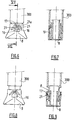
Figure 6 is a front view of a second embodiment of the invention, in a mounted state of the deshielder; -
Figure 7 is a partial cut view according to the line VII-VII ofFigure 6 ; -
Figures 8 and 9 are views corresponding toFigures 6 and 7 , showing the mounting of the deshielder on the housing; -
Figures 10 and 11 are views corresponding toFigures 6 and 7 , illustrating the removal of the deshielder with regard to the housing; -
Figures 12 and 13 are partial front views of a third embodiment of the invention, respectively in a mounted and removed position of the deshielder; -
Figure 14 is a perspective view of the deshielder of a fourth embodiment which is not part of the claimed invention; -
Figure 15 is an enlarged view of the connection between the cap and the ring of the deshielder ofFigure 14 ; -
Figure 16 is a view corresponding toFigure 15 during removal of the deshielder; -
Figure 17 is a view corresponding toFigure 15 of a fifth embodiment which is not part of the claimed invention; -
Figure 18 is a view corresponding toFigure 14 of a sixth embodiment which is not part of the claimed invention; -
Figure 19 is a view corresponding toFigure 18 of a seventh embodiment which is not part of the claimed invention; -
Figure 20 is a partial front view of an eighth embodiment which is not part of the claimed invention; -
Figure 21 is a view corresponding toFigure 20 during the removal of the deshielder; -
Figure 22 is a view corresponding toFigure 20 , the deshielder being completely removed from the housing. -
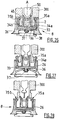
Figures 23 to 25 are views corresponding toFigures 20 to 22 , showing a ninth embodiment which is not part of the claimed invention; -
Figure 26 is a partial longitudinal cross view of a tenth embodiment which is not part of the claimed invention; -
Figure 27 is a view corresponding toFigure 26 during removal of the deshielder; -
Figure 28 is a view corresponding toFigure 26 , the deshielder being completely removed from the housing. -
Figures 29 and 30 are partial front views of a eleventh embodiment which is not part of the claimed invention, respectively in a mounted and removed positions of the deshielder; -
Figures 31 and 32 are longitudinal cross views of the device ofFigures 29 and 30 ; - Referring now to the drawings, the present invention will now be described in detail.
Figure 1 shows an exploded perspective view of a device for automatic injection according to an embodiment of the present invention and generally designated byreference number 1. Theinventive device 1 comprises ahousing 300 comprised of anupper housing assembly 100 and alower housing assembly 200 that may be connected to each other by means of a snap-fit connection, screw-type connection, bayonet connection, or other means of connecting two parts together, in an unreleasable way or not. When the device of the injection is of a single use type, the means for connecting theupper housing assembly 100 to thelower housing assembly 200 are made unreachable to the user. Acontainer 50 such as, for example, a syringe, is received in at least one of the upper andlower housing assemblies container 50 is partially received in each of the upper andlower housing assemblies container 50 has aflange 5a defined at an open proximal end, and an injection needle 6 (see, e.g.,Figure 2 ) at a substantially closed distal end 5b.Lateral walls 5 extend between the proximal and distal ends and define areservoir 5c sized and shaped to contain a predetermined amount of aproduct 3 for injection. Theinjection needle 6 may be fixed to the distal end 5b, or removable therefrom, as a matter of design choice. Theinjection needle 6 is in fluid communication with thereservoir 5c and provides an outlet port of thecontainer 50 for theproduct 3. Aneedle shield 2 is provided at the distal end of thecontainer 50 to cover and protect theneedle 6 before use of thedevice 1. Theneedle shield 2 also provides for a sealing means of the distal end of thecontainer 50 before use. Apiston 7 is provided in thecontainer 50 and which is movable within thereservoir 5c. Movement of thepiston 7 causes theproduct 3 to be expelled from saidcontainer 50 through theinjection needle 6 during the injection of theproduct 3 into the patient. - The
device 1 of the present invention is also provided with adeshielder 8 for removing theneedle shield 2. As shown inFigures 1 and2 , thedeshielder 8 comprises a tubular part carrying theneedle shield 2. Thedeshielder 8 is coupled to theneedle shield 2. Prior to use of thedevice 1, a user removes thedeshielder 8, which also removes theneedle shield 2. - The
deshielder 8 is being mounted on thehousing 300 in a separable manner, for example through breakable or snap-fit means, saiddeshielder 8 comprising tamper evidence means that are activated by the removal of at least one part of saiddeshielder 8, the at least one part of said deshielder being able to be removed from the housing by exerting a force equal or below 30 N (Newtons), preferably ranging from 2 to 30 N. - The invention concerns in particular the tamper evidence means and the separable connection between the deshielder and the body.
- A first embodiment of the invention is illustrated in
Figures 3 to 5 . - As it can be seen, the tamper evidence means of the deshielder comprise two
opposite legs 10 located on thehousing 300. Eachleg 10 comprises afirst part 11 extending outwardly from the deshielder and asecond part 12 extending longitudinally and equipped with ahook 13 extending into thedeshielder 8. Eachleg 10 is disposed in a lateral opening and is linked to thedeshielder 8 by means oflateral bridges 14 enabling theleg 10 to be pivoted or swivelled with regard to thedeshielder 8 when actuated by the user. - Each
hook 13 cooperates with acomplementary recess 15 arranged in thehousing 300. When thelegs 10 are actuated, thehooks 13 are disengaged from therecess 15 and thedeshielder 8 can be removed. On the contrary, when thelegs 10 are not actuated, thehooks 13 secure thedeshielder 8 in position with regard to thehousing 300. - In addition a
window 16 is located on thedeshielder 8, saidwindow 16 extending from the proximal end of thedeshielder 8. Afrangible tongue 17 extends into thewindow 16, in a direction substantially perpendicular to the longitudinal axis A of said device. Apeg 18 extends from thehousing 300, saidpeg 18 being engaged into thewindow 16 when thedeshielder 8 is in its non removed state, saidpeg 18 being designed to break saidfrangible tongue 17 when saiddeshielder 8 is removed from thehousing 300. - The
frangible tongue 17 and thepeg 18 are thereby forming the tamper evidence means. - The traction force exerted by the user to remove the
deshielder 8 can be considerably reduced, and is effective below or equal to 30 Newtons, because thelegs 10 hold in place thedeshielder 8 on thehousing 300 before removal. Therefore, the tamper evidence means do not have to provide such function and the strength of thefrangible tongue 17 can be reduced. - A second embodiment of the invention is shown on
Figures 6 to 11 . - In this embodiment, the components having a function similar to those detailed above are designated by the same reference.
- The tamper evidence means comprise two
pegs 18 located on thehousing 300 and extending opposite one to another from thehousing 300, twowindows 16 located on thedeshielder 8 and afrangible tongue 17 extending into eachwindow 16, in a direction substantially perpendicular to the longitudinal axis A of said device. - Each
peg 18 is engaged into the correspondingwindow 16 before activation of the tamper evidence means, saidpeg 18 being designed to break saidfrangible tongue 17 when thedeshielder 18 is removed from thehousing 300. - More particularly, each peg 18 has a trapezoidal shape, as detailed on
Figure 6 , thepeg 18 defining aslope 19 inwardly in direction of the distal end, the proximal end of the peg defining an abutment 20 (seeFigures 7 and11 ). - The
deshielder 8 receives the distal end of thehousing 300. - In addition, each
window 16 of thedeshielder 8 comprises twoleg 21 extending into it, in the proximal direction, the free ends of theleg 21 being linked by thefrangible tongue 17 in the non removed state of the deshielder. - The
peg 18 and theleg 21 are designed in such a manner that theabutment 20 is able to cooperate with thefrangible tongue 17 during removal of thedeshielder 8 so that thefrangible tongue 17 is removed from at least oneleg 21. - In addition, the
proximal edge 22 of thedeshielder 8 comprises recesses enabling the movement of thepegs 8 without coming in abutment with said edge 22 (seeFigure 11 ). - As it can be seen on
Figures 8 and 9 , when positioning for the first time thedeshielder 8 on thehousing 300, theslope 19 of thepeg 18 pushes theflexible leg 21 and thepeg 18 is inserted in the aperture delimited by theleg 21 and thefrangible tongue 17. - As it can be seen on
Figures 10 and 11 , theabutment 20 cooperates with thefrangible tongue 17 during the removal of the deshielder so that saidfrangible tongue 17 is separated from at least one of theleg 21. After complete removal of thedeshielder 8, the free ends 21a of thelegs 21 come closer one to another due to the elasticity of thelegs 21, thereby defining a stop on which thepeg 18 comes in abutment if the user intends to recap thedeshielder 8. - Consequently the
legs 21 prevent thedeshielder 8 to be put back on thehousing 300. - A third embodiment of the invention is depicted on
Figures 12 and 13 . - In this embodiment, the
window 16 extends from theproximal edge 22 of thedeshielder 8. The deshielder comprises a frangible tongue having a first andsecond tabs first end 23c connected to thedeshielder 8 and a narrowsecond end 23d connected to the other tab thereby forming a frangible point between thetabs 23, 24. - The breaking threshold of the frangible point is lower than the breaking thresholds of the connections between the first ends of the
tabs 23, 24 and thedeshielder 8. - In addition, the
peg 18 comprises afirst part 18a forming an abutment able to cooperate with thefirst tab 23a during the removal of saiddeshielder 8, and asecond part 18b able to cooperate with thesecond tab 23b during the removal of saiddeshielder 8. The first andsecond parts peg 18 are spaced one to another perpendicularly to the longitudinal axis A of said device, saiddeshielder 8 comprising a guidingtongue 24 extending between said first andsecond parts - Therefore, during removal of the
deshielder 8, thepeg 18 break the frangible point of thefrangible tongue 17 and the first and thesecond tabs tab deshielder 8 through said narrowfirst end 23c forming a pivot for the corresponding tab with regard to thedeshielder 8. - A fourth embodiment which is not part of the claimed invention is illustrated on
Figures 14 to 16 . - In this embodiment, the
deshielder 8 comprises aring 25 and acap 26, saidring 25 being mounted on thehousing 300 and frangibly connected to thecap 26. - The
cap 26 comprises a plurality ofwindows 16 extending from theproximal edge 22 of thecap 26, saidring 25 comprising a plurality offlexible hooks 27 extending into the correspondingwindows 16, eachhook 27 being frangibly connected to thecap 26 by welding. - The
cap 26 also comprises anabutment 28 extending from itsproximal edge 22 in direction of thering 25. Thisabutment 28 prevents from separating thehook 27 from thedeshielder 8 while pressing on thedeshielder 8. Indeed, theabutment 27 avoids any substantial displacement between thering 25 and thecap 26 if a user accidentally press on thecap 26. - As it can be seen on
figure 16 , theflexible hook 27 firstly tends to bend during removal thecap 26 and, when the traction force exerted by the user is sufficient, thehook 27 is separated from thecap 26. - In another embodiment which is not part of the claimed invention depicted on
Figure 17 , thering 25 comprises twoflexible hooks window 16 and arranged in the opposite direction one to another. - In a still another embodiment which is not part of the claimed invention shown on
Figure 18 , eachhook cap 26 are different. - Therefore, during removal of the deshielder by the user, the
hook 27b, which is thinner than thehook 27a, will break in a first time and thehook 27a will break in a second time. - The traction force needed for removing the
cap 26 can therefore be reduced because only onehook cap 26 at a value equal or less than 30 Newtons. - In a still another embodiment which is not part of the claimed invention depicted on
Figure 19 , thehousing 300 is equipped with cuttingelements hooks element 29b is axially spaced with regard to thecutting element 29a in direction of the distal end. - Therefore, during removal of the
cap 26, the cuttingelement 29b first breaks the connection point between thehook 27b and thecap 26. Then, the cuttingelement 27a breaks the connection point between thehook 27a and thecap 26. - This embodiment provides the advantage exposed above because only one
hook - Another embodiment which is not part of the claimed invention is illustrated on
Figures 20 to 22 . - In this embodiment the
deshielder 8 also comprises aring 25 and acap 26 mounted on thehousing 300. Thering 25 is connected to thecap 26 through at least a first and asecond connection points housing 300. More specifically, thehousing 300 and thedeshielder 8 are substantially symmetrical with regard to their longitudinal axis, defining a first and a second parts separated by the plane of symmetry. - The first part of
housing 300 is equipped with an abutment 31 (seeFigure 21 ) extending from the external face of thehousing 300 and able to cooperate with the first part of thering 25. - During removal of the
cap 26, the first part of thering 25 rests on saidabutment 31 so as to break thefirst connection point 30a, saidring 25 being deformable so that the second part of thering 25 is movable along the housing 300 (Figure 21 ). - Then, the
second connection point 30b is also broken so that thecap 26 can be completely removed from the housing (Figure 22 ). - Again, the traction force needed for removing the cap can therefore be reduced, and can be effective at 30 Newtons or less, because only one frangible connection point needs to be broken at once.
- A still another embodiment which is not part of the claimed invention is depicted on
Figures 23 to 25 . In this embodiment, thehousing 300 and thedeshielder 8 comprise a first and asecond parts housing 300 has respectively a first and asecond pegs second parts - The proximal end of the
first peg 31a is axially spaced from the proximal end of thesecond pegs 31b in direction of the distal end of the device. - The first and the
second pegs ring 25, thering 25 being linked to thecap 26 by a first and asecond legs second parts deshielder 8. The first and thesecond connection points legs - During removal of the
cap 26, thefirst peg 31a abuts on the first part of thering 25, thereby breaking thefirst connection point 30a. Therefore, thering 25 which is still linked to thecap 26 through thesecond leg 32b is progressively deformed (Figure 24 ). Then, thesecond peg 31b abuts on the second part of thering 25, thereby breaking thesecond connection point 30b (Figure 25 ). Consequently, thering 25 is completely separated from thecap 26, saidcap 26 being able to be completely removed from thehousing 300. - A still another embodiment which is not part of the claimed invention is shown on
Figures 26 to 28 . - As it can be seen on these Figures, the
deshielder 8 comprises asleeve 33 having twodeformable arms 34a, 34b equipped with ahook housing 300 in a mounted state of thedeshielder 8, thereby forming press-fit means. - The
sleeve 33 is inserted, at least partly, into atubular cap 26, thesleeve 33 being movable along the longitudinal axis A of thedeshielder 8 into thecap 26 between an inserted position (Figure 26 ) in which saiddeformable arms 34a, 34b are inserted into thesleeve 33 so that they cannot be deformed and a pulled out position (Figure 27 ) in which thearms 34a, 34b are pulled out of thesleeve 33 and can be deformed. - In addition, the
cap 26 comprisesflexible wings 36 extending substantially perpendicular to the longitudinal axis A of thedeshielder 8, theflexible wings 36 comprising free ends spaced one to another thereby defining an opening, thesleeve 33 comprising, at its distal end, agrooved pin 37 engaged into said opening. - The distal end of the
cap 26 is equipped with a top 38 protecting the groovedpin 37 and thewings 36. - Therefore, as it can be seen on
Figure 27 , during removal of thedeshielder 8, theflexible wings 36 are progressively deformed so that thesleeve 33 is pulled out of thecap 26. In this position, thearms 34a, 34b can be deformed in order to disengage thedeshielder 8 from thehousing 300. - After the removal of the
deshielder 8, thesleeve 33 is inserted into thecap 26 under the effect of theflexible wings 36 and saidhooks housing 300, thereby preventing thedeshielder 8 to be put back on thehousing 300, as it can be seen onFigure 28 . - Another embodiment which is not part of the claimed invention is shown on
Figures 29 to 32 . In this embodiment, thedeshielder 8 comprises two oppositeflexible legs 39 extending inwardly into thedeshielder 8, eachleg 39 cooperating with acomplementary recess 40 formed in thehousing 300, thereby forming snap-fit means. As it can be seen onFigure 32 , the free ends 41 of theflexible legs 39 form abutments for thedistal end 42 of thehousing 300 after the removal of thedeshielder 8 from thehousing 300, thereby preventing thedeshielder 8 to be put back on thehousing 300.
said at least one part of said deshielder can be removed from the housing by exerting a force equal or below 30 N, preferably from 2 to 30 N, and in that said tamper evidence means comprise at least one peg located on the housing, at least one window located on the deshielder and at least one frangible tongue extending into the window, in a direction substantially perpendicular to the longitudinal axis of said device, said peg being engaged into the window before activation of the tamper evidence means, said peg being designed to break said frangible tongue when said part of the deshielder is removed from the housing.
Claims (7)
- Device (1) for automatic injection of a product into an injection site, said device (1) comprising:- a housing (300) capable of receiving a container (50);- a needle shield (2) for protection of a needle (6) provided on the container (6) prior to use of said device; and- a deshielder (8) for removing said needle shield (2) from said device (1), said deshielder (8) being coupled to said needle shield (2) and being mounted on the housing (300) in a separable manner, for example through breakable or snap-fit means, said deshielder (8) comprising tamper evidence means that are activated by the removal of at least one part of said deshielder (8),characterized in that
said at least one part of said deshielder (8) is removable from the housing (300) upon application of a force equal to or below 30 N, preferably ranging from 2 to 30N, and in that said tamper evidence means comprise at least one peg (18) located on the housing (300), at least one window (16) located on the deshielder (8) and at least one frangible tongue (17) extending into the window (16), in a direction substantially perpendicular to the longitudinal axis (A) of said device (1), said peg (18) being engaged into the window (16) before activation of the tamper evidence means, said peg (18) being designed to break said frangible tongue (17) when said part of the deshielder (8) is removed from the housing. - Device (1) according to claim 1, characterized in that said window (16) extending from the proximal end (22) of the deshielder (8),
the deshielder (8) comprises at least one leg (10) articulated on the deshielder (8) and extending along the longitudinal axis (A) of said deshielder (8), said leg (10) comprising an end forming a hook (13) that cooperate with at least one complementary recess (15) formed in the housing (300), so as to couple said deshielder (8) to said housing (300). - Device (1) according to claim 1, characterized in that the deshielder (8) comprises a tubular part receiving a part of the housing (300), said window (16) being formed on said tubular part, said deshielder (8) comprising at least two legs (21) extending into the window (16), in the proximal direction, the free ends of the legs (21) being linked by a frangible tongue (17).
- Device (1) according to claim 3, characterized in that, in the removed state of the deshielder (8), the frangible tongue (17) is separated from at least one of the legs (21), the free ends of said legs (21) then defining a stop on which the peg (18) comes in abutment, thereby preventing the deshielder (8) to be put back on the housing (300).
- Device (1) according to claim 1, characterized in that said at least one frangible tongue (17) comprises a first and second tabs (23a, 23b), each tab comprising a narrow first end connected to the deshielder (8) and a narrow second end connected to the other tab thereby forming a frangible point between the tabs (23a, 23b), said at least one peg comprising a first part (23a) forming an abutment able to cooperate with the first tab (23a) during the removal of said deshielder (8), and a second part (18b) able to cooperate with the second tab (23b) during the removal of said deshielder (8).
- Device (1) according to claim 5, characterized in that the breaking threshold of the frangible point is lower than the breaking thresholds of the connections between the first ends of the tabs (23a, 23b) and the deshielder (8).
- Device (1) according to claims 5 and 6, characterized in that the first and second parts (18a, 18b) of said peg are spaced one to another perpendicularly to the longitudinal axis (A) of said device (1), said deshielder (8) comprising a guiding tongue (24) extending between said first and second parts (18a, 18b) of said peg.
Applications Claiming Priority (1)
| Application Number | Priority Date | Filing Date | Title |
|---|---|---|---|
| PCT/IB2007/003974 WO2009040603A1 (en) | 2007-09-25 | 2007-09-25 | Autoinjector with deshielder comprising tamper evidence means |
Publications (2)
| Publication Number | Publication Date |
|---|---|
| EP2211944A1 EP2211944A1 (en) | 2010-08-04 |
| EP2211944B1 true EP2211944B1 (en) | 2019-05-22 |
Family
ID=39322466
Family Applications (1)
| Application Number | Title | Priority Date | Filing Date |
|---|---|---|---|
| EP07859096.5A Active EP2211944B1 (en) | 2007-09-25 | 2007-09-25 | Autoinjector with deshielder comprising tamper evidence means |
Country Status (6)
| Country | Link |
|---|---|
| US (2) | US8814828B2 (en) |
| EP (1) | EP2211944B1 (en) |
| JP (1) | JP5216859B2 (en) |
| CN (1) | CN101868270B (en) |
| ES (1) | ES2742504T3 (en) |
| WO (1) | WO2009040603A1 (en) |
Families Citing this family (80)
| Publication number | Priority date | Publication date | Assignee | Title |
|---|---|---|---|---|
| GB0414054D0 (en) | 2004-06-23 | 2004-07-28 | Owen Mumford Ltd | Improvements relating to automatic injection devices |
| TWI498137B (en) | 2006-06-30 | 2015-09-01 | Abbvie Biotechnology Ltd | Automatic injection device |
| JP5216859B2 (en) * | 2007-09-25 | 2013-06-19 | ベクトン・ディキンソン・フランス・エス.エー.エス. | Automatic syringe with shielding separation with means to prove modification |
| US9173997B2 (en) | 2007-10-02 | 2015-11-03 | Medimop Medical Projects Ltd. | External drug pump |
| CN104324438B (en) * | 2008-01-11 | 2017-06-16 | Ucb医药有限公司 | For the delivery system of patient with rheumatoid arthritis |
| MX2011011541A (en) | 2009-04-29 | 2012-02-28 | Abbott Biotech Ltd | Automatic injection device. |
| DK2255842T4 (en) | 2009-05-26 | 2023-07-24 | Shl Medical Ag | Needle cap assembly |
| JP5598903B2 (en) | 2010-01-29 | 2014-10-01 | 富士電機エフテック株式会社 | Electric syringe for chemicals |
| EP2361648A1 (en) * | 2010-02-18 | 2011-08-31 | Sanofi-Aventis Deutschland GmbH | Remover for a protective needle shield |
| EP2536452B1 (en) | 2010-02-18 | 2018-08-29 | Sanofi-Aventis Deutschland GmbH | Auto-injector |
| US8353869B2 (en) * | 2010-11-02 | 2013-01-15 | Baxa Corporation | Anti-tampering apparatus and method for drug delivery devices |
| MX336571B (en) | 2011-01-24 | 2016-01-25 | Elcam Medical Agricultural Cooperative Ass Ltd | INJECTOR. |
| MX388000B (en) * | 2011-01-24 | 2025-03-19 | Abbvie Biotechnology Ltd | SEPARATION OF NEEDLE GUARDS FROM SYRINGES AND AUTOMATIC INJECTION DEVICES. |
| RU2602039C2 (en) | 2011-01-24 | 2016-11-10 | Эббви Байотекнолоджи Лтд. | Automatic injection devices having overmoulded gripping surfaces |
| EP2670459B1 (en) * | 2011-01-31 | 2016-11-09 | SHL Group AB | Coupling arrangement |
| US20140052102A1 (en) * | 2011-05-06 | 2014-02-20 | Sanofi-Aventis Deutschland Gmbh | Reuse Protection for Disposable Parts |
| WO2012161685A1 (en) * | 2011-05-23 | 2012-11-29 | Boehringer Ingelheim International Gmbh | Nebulizer |
| ES2542250T3 (en) | 2011-06-02 | 2015-08-03 | Ucb Biopharma Sprl | Autoinjector |
| DK2729203T4 (en) | 2011-07-05 | 2023-10-30 | Shl Medical Ag | Needle sheath remover assembly |
| RU2626132C2 (en) | 2011-09-09 | 2017-07-21 | Мерк Патент Гмбх | Automated injector for adrenaline injection |
| WO2013041504A1 (en) | 2011-09-20 | 2013-03-28 | Sanofi-Aventis Deutschland Gmbh | Cap assembly for a drug delivery device |
| EP2572741A1 (en) * | 2011-09-23 | 2013-03-27 | Sanofi-Aventis Deutschland GmbH | Medicament delivery device and actuation mechanism for a drug delivery device |
| JP5869825B2 (en) * | 2011-10-03 | 2016-02-24 | 大成化工株式会社 | Barrel with cap, cap, and prefilled syringe |
| US9302053B2 (en) | 2011-12-06 | 2016-04-05 | Shl Group Ab | Injection device |
| USD724203S1 (en) | 2012-06-04 | 2015-03-10 | Ucb Pharma S.A. | Drive device for administering medication |
| EP2879737B1 (en) | 2012-07-30 | 2018-09-12 | UCB Biopharma SPRL | Auto-injector |
| USD726901S1 (en) | 2012-07-30 | 2015-04-14 | Ucb Pharma S.A. | Drive device for administering medication |
| EP2879738B1 (en) | 2012-07-30 | 2019-09-11 | UCB Biopharma SPRL | Auto-injector |
| US9764101B2 (en) | 2012-07-30 | 2017-09-19 | Ucb Biopharma Sprl | Auto-injector |
| US9757521B2 (en) | 2012-07-30 | 2017-09-12 | Ucb Biopharma Sprl | Auto-injector |
| FR2999436B1 (en) * | 2012-12-14 | 2016-02-05 | Transformation Des Elastomeres A Usages Medicaux Et Ind Soc D | NEEDLE PROTECTION SYSTEM OF AN INJECTION DEVICE. |
| EP2823841A1 (en) | 2013-07-09 | 2015-01-14 | Sanofi-Aventis Deutschland GmbH | Autoinjector |
| PL3038682T3 (en) | 2013-08-29 | 2019-04-30 | Sanofi Sa | Cap for a medicament container |
| DE102013112654A1 (en) | 2013-11-15 | 2015-05-21 | Gerresheimer Regensburg Gmbh | Syringe for injection of liquid substances |
| US10342925B2 (en) | 2014-01-27 | 2019-07-09 | Ucb Biopharma Sprl | Auto-injector |
| EP3099350B1 (en) | 2014-01-27 | 2019-06-12 | UCB Biopharma SPRL | Auto-injector |
| US9821123B2 (en) | 2014-01-27 | 2017-11-21 | Ucb Biopharma Sprl | Auto-injector |
| HK1226341A1 (en) * | 2014-02-11 | 2017-09-29 | Eli Lilly And Company | Rigid needle shield gripping cap assembly |
| EP2923716A1 (en) | 2014-03-28 | 2015-09-30 | Sanofi-Aventis Deutschland GmbH | Cap having a sheath removal mechanism |
| EP2923714A1 (en) | 2014-03-28 | 2015-09-30 | Sanofi-Aventis Deutschland GmbH | Autoinjector triggered by skin contact |
| WO2016055334A1 (en) | 2014-10-08 | 2016-04-14 | Carebay Europe Ltd | Medicament delivery device |
| JP6625566B2 (en) * | 2015-01-20 | 2019-12-25 | テルモ株式会社 | Injection needle assembly and syringe for injecting a drug solution into the upper layer of skin having the same |
| ES2722002T3 (en) * | 2015-06-15 | 2019-08-06 | Gerresheimer Regensburg Gmbh | Safety device for a syringe |
| US10576207B2 (en) | 2015-10-09 | 2020-03-03 | West Pharma. Services IL, Ltd. | Angled syringe patch injector |
| JP7017512B2 (en) * | 2015-10-09 | 2022-02-08 | ウェスト ファーマ サービシーズ イスラエル リミテッド | Bending fluid path type accessories for filled fluid containers |
| WO2017087888A1 (en) | 2015-11-18 | 2017-05-26 | President And Fellows Of Harvard College | Systems and methods for monitoring, managing, and treating asthma and anaphylaxis |
| JP6542481B2 (en) | 2016-01-21 | 2019-07-10 | ウェスト ファーマ サービシーズ イスラエル リミテッド | system |
| EP3711793B1 (en) | 2016-01-21 | 2021-12-01 | West Pharma Services IL, Ltd. | A method of connecting a cartridge to an automatic injector |
| US11311674B2 (en) | 2016-01-21 | 2022-04-26 | West Pharma. Services IL, Ltd. | Medicament delivery device comprising a visual indicator |
| US11389597B2 (en) | 2016-03-16 | 2022-07-19 | West Pharma. Services IL, Ltd. | Staged telescopic screw assembly having different visual indicators |
| USD819198S1 (en) | 2016-04-28 | 2018-05-29 | Amgen Inc. | Autoinjector with removable cap |
| US10300214B2 (en) * | 2016-07-27 | 2019-05-28 | Shl Medical Ag | Cap assembly for a medicament delivery device |
| US10583255B2 (en) * | 2016-07-27 | 2020-03-10 | Shl Medical Ag | Medicament container assembly for a medicament delivery device |
| CH712753A2 (en) | 2016-07-28 | 2018-01-31 | Tecpharma Licensing Ag | Separating a needle cap from a product container and method of mounting an injection device. |
| EP3978047B1 (en) | 2016-08-01 | 2023-08-23 | West Pharma Services IL, Ltd | Partial door closure prevention spring |
| EP3490643B1 (en) | 2016-08-01 | 2021-10-27 | West Pharma. Services Il, Ltd. | Anti-rotation cartridge pin |
| CN109562233B (en) | 2016-08-02 | 2022-04-15 | 赛诺菲-安万特德国有限公司 | drug delivery device |
| EP3525849A1 (en) * | 2016-10-13 | 2019-08-21 | SHL Medical AG | A sub-assembly, a medicament delivery device and a method of assembling a sub-assembly |
| US20200139046A1 (en) * | 2017-05-23 | 2020-05-07 | Merck Patent Gmbh | Auto injector with hollow plunger rod |
| EP3630226B1 (en) | 2017-05-30 | 2025-10-22 | West Pharma. Services Il, Ltd. | Modular drive train for wearable injector |
| EP3466467B1 (en) * | 2017-10-06 | 2022-04-27 | SHL Medical AG | Needle shield assembly |
| US11452821B2 (en) | 2017-10-12 | 2022-09-27 | Eli Lilly And Company | Needle shield puller for drug delivery system |
| GB2570319B (en) | 2018-01-19 | 2021-01-06 | Consort Medical Plc | A medicament delivery device |
| US11040142B2 (en) * | 2018-03-12 | 2021-06-22 | E3D A.C.A.L Ltd | Automatic injection device with a dampening element |
| GB2580133B (en) | 2018-12-21 | 2023-04-12 | Janssen Pharmaceuticals Inc | Accessory including a slot for a flange of an injection device |
| GB2580141B (en) | 2018-12-21 | 2023-04-12 | Janssen Pharmaceuticals Inc | Accessory for an injection device including a grip for a needle cap |
| GB2580142B (en) | 2018-12-21 | 2023-04-12 | Janssen Pharmaceuticals Inc | Accessory for an injection including a pivotable cover |
| USD958330S1 (en) | 2018-12-21 | 2022-07-19 | Janssen Pharmaceuticals, Inc. | Injection device accessory |
| EP3980098A1 (en) * | 2019-06-04 | 2022-04-13 | Sanofi | Apparatus for removing a needle shield |
| USD1010811S1 (en) | 2019-09-30 | 2024-01-09 | Amgen Inc. | Handheld drug delivery device |
| USD1030041S1 (en) | 2020-01-14 | 2024-06-04 | Amgen Inc. | Handheld drug delivery device |
| USD1030040S1 (en) | 2020-01-14 | 2024-06-04 | Amgen Inc. | Handheld drug delivery device |
| JP2021500644S (en) | 2020-11-05 | 2022-12-27 | Syringe | |
| USD973866S1 (en) | 2020-11-05 | 2022-12-27 | Amgen Inc. | Handheld drug delivery device |
| USD974547S1 (en) | 2020-11-05 | 2023-01-03 | Amgen Inc. | Handheld drug delivery device |
| BR112023018234A2 (en) * | 2021-03-10 | 2023-10-24 | Amgen Inc | DRUG ADMINISTRATION DEVICE HAVING A REMOVABLE COVER |
| USD985117S1 (en) | 2021-03-10 | 2023-05-02 | Amgen Inc. | Handheld drug delivery device |
| USD985118S1 (en) | 2021-03-10 | 2023-05-02 | Amgen Inc. | Handheld drug delivery device |
| USD985116S1 (en) | 2021-03-10 | 2023-05-02 | Amgen Inc. | Handheld drug delivery device |
| USD985119S1 (en) | 2021-03-30 | 2023-05-02 | Amgen Inc. | Handheld drug delivery device |
Family Cites Families (31)
| Publication number | Priority date | Publication date | Assignee | Title |
|---|---|---|---|---|
| US3601273A (en) * | 1969-01-31 | 1971-08-24 | Aluminum Co Of America | Pilferproof closure with vertical weakening lines |
| US4474734A (en) * | 1983-07-05 | 1984-10-02 | Microbiological Applications, Inc. | Syringe shield and closure sterilization method |
| GB8319444D0 (en) * | 1983-07-19 | 1983-08-17 | Nat Plastics Ltd | Container closure |
| US4667837A (en) * | 1986-06-05 | 1987-05-26 | International Medical Industries, Incorporated | Tamper proof cap |
| US5360404A (en) * | 1988-12-14 | 1994-11-01 | Inviro Medical Devices Ltd. | Needle guard and needle assembly for syringe |
| US4929232A (en) | 1989-03-30 | 1990-05-29 | Becton, Dickinson And Company | Syringe having tamper evidence features |
| US4967920A (en) * | 1989-06-26 | 1990-11-06 | Continental White Cap, Inc. | Partial tamper band |
| GB8926825D0 (en) | 1989-11-28 | 1990-01-17 | Glaxo Group Ltd | Device |
| GB9200219D0 (en) * | 1992-01-07 | 1992-02-26 | Medimech Int Ltd | Automatic injectors |
| US5540666A (en) | 1993-03-31 | 1996-07-30 | Immuno Aktiengesellschaft | Cannula shield and injection syringe system |
| US5344404A (en) * | 1993-08-13 | 1994-09-06 | Becton, Dickinson And Company | Syringe assembly having a non-resuable needle shield |
| US5506015A (en) * | 1994-01-07 | 1996-04-09 | Sherwood Medical Company | Tamper-evident closure seal |
| DE19717033A1 (en) * | 1997-04-23 | 1998-11-12 | Schott Glas | Needle cap for a prefillable disposable syringe |
| FR2799376B1 (en) | 1999-10-07 | 2002-01-18 | Marc Brunel | SINGLE USE INJECTION DEVICE |
| US6193688B1 (en) * | 2000-07-17 | 2001-02-27 | Bracco Diagnostics, Inc. | Tamper evident protector cap for pre-filled syringe barrels |
| FR2812817B1 (en) * | 2000-08-09 | 2002-10-31 | Sanofi Synthelabo | PROTECTION DEVICE FOR A SYRINGE NEEDLE |
| US7169134B2 (en) * | 2002-03-26 | 2007-01-30 | Ultradent Products, Inc. | Apparatus with rotatable valve syringe |
| US20040225258A1 (en) * | 2002-03-30 | 2004-11-11 | Ernest Balestracci | Tamper evident overcap for a container |
| DE10316127A1 (en) * | 2003-04-09 | 2004-11-04 | Arzneimittel Gmbh Apotheker Vetter & Co. Ravensburg | Pre-filled syringe or cartridge for medical purposes |
| EP1502616A1 (en) * | 2003-08-01 | 2005-02-02 | Bünder Glas GmbH | Needle protector for a glass syringe |
| DE602004027287D1 (en) * | 2003-10-27 | 2010-07-01 | Portola Packaging Inc | BY TURNING TO OPENING CLOSURE WITH APPROVED RAPID MEMBRANE |
| GB2410188B (en) * | 2004-01-23 | 2006-01-25 | Medical House Plc | Injection device |
| CA2520201A1 (en) * | 2004-09-13 | 2006-03-13 | Jms Co., Ltd. | Safeguard cap, injection needle with safeguard cap, and medical device with safeguard cap |
| EP1814616A1 (en) * | 2004-11-04 | 2007-08-08 | Sid Technologies Llc | Automatic injector |
| GB2424836B (en) * | 2005-04-06 | 2010-09-22 | Cilag Ag Int | Injection device (bayonet cap removal) |
| US8043300B2 (en) * | 2005-07-05 | 2011-10-25 | Alcon, Inc. | Handpiece tip assembly |
| US20110098656A1 (en) * | 2005-09-27 | 2011-04-28 | Burnell Rosie L | Auto-injection device with needle protecting cap having outer and inner sleeves |
| DE102005054075A1 (en) * | 2005-11-12 | 2007-05-16 | Vetter & Co Apotheker | Needle attachment for a syringe or carpule |
| FR2905273B1 (en) * | 2006-09-06 | 2009-04-03 | Becton Dickinson France Soc Pa | AUTOMATIC INJECTION DEVICE WITH TIMING MEANS. |
| JP5216859B2 (en) * | 2007-09-25 | 2013-06-19 | ベクトン・ディキンソン・フランス・エス.エー.エス. | Automatic syringe with shielding separation with means to prove modification |
| US8313470B2 (en) * | 2007-09-25 | 2012-11-20 | Becton Dickinson France | Autoinjector |
-
2007
- 2007-09-25 JP JP2010526381A patent/JP5216859B2/en active Active
- 2007-09-25 US US12/679,928 patent/US8814828B2/en active Active
- 2007-09-25 EP EP07859096.5A patent/EP2211944B1/en active Active
- 2007-09-25 WO PCT/IB2007/003974 patent/WO2009040603A1/en not_active Ceased
- 2007-09-25 ES ES07859096T patent/ES2742504T3/en active Active
- 2007-09-25 CN CN2007801016077A patent/CN101868270B/en active Active
-
2014
- 2014-08-21 US US14/464,931 patent/US10179214B2/en active Active
Non-Patent Citations (1)
| Title |
|---|
| None * |
Also Published As
| Publication number | Publication date |
|---|---|
| US10179214B2 (en) | 2019-01-15 |
| EP2211944A1 (en) | 2010-08-04 |
| US8814828B2 (en) | 2014-08-26 |
| WO2009040603A1 (en) | 2009-04-02 |
| JP2010540055A (en) | 2010-12-24 |
| CN101868270B (en) | 2013-10-16 |
| US20100268169A1 (en) | 2010-10-21 |
| US20140364805A1 (en) | 2014-12-11 |
| CN101868270A (en) | 2010-10-20 |
| ES2742504T3 (en) | 2020-02-14 |
| JP5216859B2 (en) | 2013-06-19 |
Similar Documents
| Publication | Publication Date | Title |
|---|---|---|
| US8814828B2 (en) | Autoinjector with deshielder comprising tamper evidence means | |
| KR102257736B1 (en) | Drug delivery device with cap assembly | |
| RU2481859C2 (en) | Needle prick protector | |
| US5562624A (en) | Non-reusable safety syringe | |
| EP3600496B1 (en) | Safety assembly for a medical delivery device | |
| AU2001270707B2 (en) | Device for protecting a syringe needle | |
| EP3204093B1 (en) | Medicament delivery device | |
| RS59251B1 (en) | NEEDLE SHIELD COVER ASSEMBLY ASSEMBLY | |
| US5372590A (en) | Multi-celled safety package, needle guard and safety disposal module with sleeve for prefilled medication cartridges | |
| EP2887983B1 (en) | Medicament delivery device | |
| JP2001521793A (en) | Medical safety syringe | |
| US20050148994A1 (en) | Vial adapter having a needle-free valve for use with vial closures of different sizes | |
| EP3528871B1 (en) | Medicament delivery device having a cap assembly | |
| JP7209839B2 (en) | anti-actuation cap assembly | |
| US20180200487A1 (en) | Needle assemblies with safety systems and manufacturing method therefor | |
| WO1992006725A1 (en) | Disposal module with sleeve for prefilled cartridges | |
| JP5061246B2 (en) | Injection device and method of assembly and operation | |
| KR20100087076A (en) | Safety syringe with plunger locking means | |
| EP3856297B1 (en) | Needle shield remover | |
| WO2008019430A1 (en) | Single use self-disabling syringe | |
| US20240001034A1 (en) | A sub-assembly for a medicament delivery device | |
| JP7403760B2 (en) | medical connectors | |
| JP2024528047A (en) | Safe Catheter Assembly | |
| KR20250004054A (en) | Protective device for syringe needle tube | |
| HK40117747A (en) | Protective device for a needle tube of a syringe |
Legal Events
| Date | Code | Title | Description |
|---|---|---|---|
| PUAI | Public reference made under article 153(3) epc to a published international application that has entered the european phase |
Free format text: ORIGINAL CODE: 0009012 |
|
| 17P | Request for examination filed |
Effective date: 20100422 |
|
| AK | Designated contracting states |
Kind code of ref document: A1 Designated state(s): AT BE BG CH CY CZ DE DK EE ES FI FR GB GR HU IE IS IT LI LT LU LV MC MT NL PL PT RO SE SI SK TR |
|
| AX | Request for extension of the european patent |
Extension state: AL BA HR MK RS |
|
| RIN1 | Information on inventor provided before grant (corrected) |
Inventor name: ABRY, HERVE Inventor name: RICH, VERNON Inventor name: BLANC, JEROME Inventor name: MARITAN, LIONEL Inventor name: LLEWELLYN-HYDE, DAVID Inventor name: PEROT, FREDERIC |
|
| DAX | Request for extension of the european patent (deleted) | ||
| 17Q | First examination report despatched |
Effective date: 20160706 |
|
| STAA | Information on the status of an ep patent application or granted ep patent |
Free format text: STATUS: EXAMINATION IS IN PROGRESS |
|
| GRAP | Despatch of communication of intention to grant a patent |
Free format text: ORIGINAL CODE: EPIDOSNIGR1 |
|
| STAA | Information on the status of an ep patent application or granted ep patent |
Free format text: STATUS: GRANT OF PATENT IS INTENDED |
|
| INTG | Intention to grant announced |
Effective date: 20181204 |
|
| GRAS | Grant fee paid |
Free format text: ORIGINAL CODE: EPIDOSNIGR3 |
|
| GRAA | (expected) grant |
Free format text: ORIGINAL CODE: 0009210 |
|
| STAA | Information on the status of an ep patent application or granted ep patent |
Free format text: STATUS: THE PATENT HAS BEEN GRANTED |
|
| AK | Designated contracting states |
Kind code of ref document: B1 Designated state(s): AT BE BG CH CY CZ DE DK EE ES FI FR GB GR HU IE IS IT LI LT LU LV MC MT NL PL PT RO SE SI SK TR |
|
| REG | Reference to a national code |
Ref country code: GB Ref legal event code: FG4D |
|
| REG | Reference to a national code |
Ref country code: CH Ref legal event code: EP |
|
| REG | Reference to a national code |
Ref country code: IE Ref legal event code: FG4D |
|
| REG | Reference to a national code |
Ref country code: DE Ref legal event code: R096 Ref document number: 602007058459 Country of ref document: DE |
|
| REG | Reference to a national code |
Ref country code: AT Ref legal event code: REF Ref document number: 1135321 Country of ref document: AT Kind code of ref document: T Effective date: 20190615 |
|
| REG | Reference to a national code |
Ref country code: NL Ref legal event code: MP Effective date: 20190522 |
|
| REG | Reference to a national code |
Ref country code: LT Ref legal event code: MG4D |
|
| PG25 | Lapsed in a contracting state [announced via postgrant information from national office to epo] |
Ref country code: NL Free format text: LAPSE BECAUSE OF FAILURE TO SUBMIT A TRANSLATION OF THE DESCRIPTION OR TO PAY THE FEE WITHIN THE PRESCRIBED TIME-LIMIT Effective date: 20190522 Ref country code: SE Free format text: LAPSE BECAUSE OF FAILURE TO SUBMIT A TRANSLATION OF THE DESCRIPTION OR TO PAY THE FEE WITHIN THE PRESCRIBED TIME-LIMIT Effective date: 20190522 Ref country code: LT Free format text: LAPSE BECAUSE OF FAILURE TO SUBMIT A TRANSLATION OF THE DESCRIPTION OR TO PAY THE FEE WITHIN THE PRESCRIBED TIME-LIMIT Effective date: 20190522 Ref country code: PT Free format text: LAPSE BECAUSE OF FAILURE TO SUBMIT A TRANSLATION OF THE DESCRIPTION OR TO PAY THE FEE WITHIN THE PRESCRIBED TIME-LIMIT Effective date: 20190922 Ref country code: FI Free format text: LAPSE BECAUSE OF FAILURE TO SUBMIT A TRANSLATION OF THE DESCRIPTION OR TO PAY THE FEE WITHIN THE PRESCRIBED TIME-LIMIT Effective date: 20190522 |
|
| PG25 | Lapsed in a contracting state [announced via postgrant information from national office to epo] |
Ref country code: GR Free format text: LAPSE BECAUSE OF FAILURE TO SUBMIT A TRANSLATION OF THE DESCRIPTION OR TO PAY THE FEE WITHIN THE PRESCRIBED TIME-LIMIT Effective date: 20190823 Ref country code: BG Free format text: LAPSE BECAUSE OF FAILURE TO SUBMIT A TRANSLATION OF THE DESCRIPTION OR TO PAY THE FEE WITHIN THE PRESCRIBED TIME-LIMIT Effective date: 20190822 Ref country code: LV Free format text: LAPSE BECAUSE OF FAILURE TO SUBMIT A TRANSLATION OF THE DESCRIPTION OR TO PAY THE FEE WITHIN THE PRESCRIBED TIME-LIMIT Effective date: 20190522 |
|
| REG | Reference to a national code |
Ref country code: AT Ref legal event code: MK05 Ref document number: 1135321 Country of ref document: AT Kind code of ref document: T Effective date: 20190522 |
|
| PG25 | Lapsed in a contracting state [announced via postgrant information from national office to epo] |
Ref country code: DK Free format text: LAPSE BECAUSE OF FAILURE TO SUBMIT A TRANSLATION OF THE DESCRIPTION OR TO PAY THE FEE WITHIN THE PRESCRIBED TIME-LIMIT Effective date: 20190522 Ref country code: AT Free format text: LAPSE BECAUSE OF FAILURE TO SUBMIT A TRANSLATION OF THE DESCRIPTION OR TO PAY THE FEE WITHIN THE PRESCRIBED TIME-LIMIT Effective date: 20190522 Ref country code: EE Free format text: LAPSE BECAUSE OF FAILURE TO SUBMIT A TRANSLATION OF THE DESCRIPTION OR TO PAY THE FEE WITHIN THE PRESCRIBED TIME-LIMIT Effective date: 20190522 Ref country code: SK Free format text: LAPSE BECAUSE OF FAILURE TO SUBMIT A TRANSLATION OF THE DESCRIPTION OR TO PAY THE FEE WITHIN THE PRESCRIBED TIME-LIMIT Effective date: 20190522 Ref country code: RO Free format text: LAPSE BECAUSE OF FAILURE TO SUBMIT A TRANSLATION OF THE DESCRIPTION OR TO PAY THE FEE WITHIN THE PRESCRIBED TIME-LIMIT Effective date: 20190522 Ref country code: CZ Free format text: LAPSE BECAUSE OF FAILURE TO SUBMIT A TRANSLATION OF THE DESCRIPTION OR TO PAY THE FEE WITHIN THE PRESCRIBED TIME-LIMIT Effective date: 20190522 |
|
| REG | Reference to a national code |
Ref country code: ES Ref legal event code: FG2A Ref document number: 2742504 Country of ref document: ES Kind code of ref document: T3 Effective date: 20200214 |
|
| REG | Reference to a national code |
Ref country code: DE Ref legal event code: R097 Ref document number: 602007058459 Country of ref document: DE |
|
| PLBE | No opposition filed within time limit |
Free format text: ORIGINAL CODE: 0009261 |
|
| STAA | Information on the status of an ep patent application or granted ep patent |
Free format text: STATUS: NO OPPOSITION FILED WITHIN TIME LIMIT |
|
| PG25 | Lapsed in a contracting state [announced via postgrant information from national office to epo] |
Ref country code: TR Free format text: LAPSE BECAUSE OF FAILURE TO SUBMIT A TRANSLATION OF THE DESCRIPTION OR TO PAY THE FEE WITHIN THE PRESCRIBED TIME-LIMIT Effective date: 20190522 |
|
| 26N | No opposition filed |
Effective date: 20200225 |
|
| PG25 | Lapsed in a contracting state [announced via postgrant information from national office to epo] |
Ref country code: PL Free format text: LAPSE BECAUSE OF FAILURE TO SUBMIT A TRANSLATION OF THE DESCRIPTION OR TO PAY THE FEE WITHIN THE PRESCRIBED TIME-LIMIT Effective date: 20190522 |
|
| PG25 | Lapsed in a contracting state [announced via postgrant information from national office to epo] |
Ref country code: SI Free format text: LAPSE BECAUSE OF FAILURE TO SUBMIT A TRANSLATION OF THE DESCRIPTION OR TO PAY THE FEE WITHIN THE PRESCRIBED TIME-LIMIT Effective date: 20190522 Ref country code: MC Free format text: LAPSE BECAUSE OF FAILURE TO SUBMIT A TRANSLATION OF THE DESCRIPTION OR TO PAY THE FEE WITHIN THE PRESCRIBED TIME-LIMIT Effective date: 20190522 |
|
| REG | Reference to a national code |
Ref country code: CH Ref legal event code: PL |
|
| PG25 | Lapsed in a contracting state [announced via postgrant information from national office to epo] |
Ref country code: CH Free format text: LAPSE BECAUSE OF NON-PAYMENT OF DUE FEES Effective date: 20190930 Ref country code: LI Free format text: LAPSE BECAUSE OF NON-PAYMENT OF DUE FEES Effective date: 20190930 Ref country code: LU Free format text: LAPSE BECAUSE OF NON-PAYMENT OF DUE FEES Effective date: 20190925 Ref country code: IE Free format text: LAPSE BECAUSE OF NON-PAYMENT OF DUE FEES Effective date: 20190925 |
|
| REG | Reference to a national code |
Ref country code: BE Ref legal event code: MM Effective date: 20190930 |
|
| PG25 | Lapsed in a contracting state [announced via postgrant information from national office to epo] |
Ref country code: BE Free format text: LAPSE BECAUSE OF NON-PAYMENT OF DUE FEES Effective date: 20190930 |
|
| PG25 | Lapsed in a contracting state [announced via postgrant information from national office to epo] |
Ref country code: CY Free format text: LAPSE BECAUSE OF FAILURE TO SUBMIT A TRANSLATION OF THE DESCRIPTION OR TO PAY THE FEE WITHIN THE PRESCRIBED TIME-LIMIT Effective date: 20190522 |
|
| PG25 | Lapsed in a contracting state [announced via postgrant information from national office to epo] |
Ref country code: IS Free format text: LAPSE BECAUSE OF FAILURE TO SUBMIT A TRANSLATION OF THE DESCRIPTION OR TO PAY THE FEE WITHIN THE PRESCRIBED TIME-LIMIT Effective date: 20190922 |
|
| PG25 | Lapsed in a contracting state [announced via postgrant information from national office to epo] |
Ref country code: HU Free format text: LAPSE BECAUSE OF FAILURE TO SUBMIT A TRANSLATION OF THE DESCRIPTION OR TO PAY THE FEE WITHIN THE PRESCRIBED TIME-LIMIT; INVALID AB INITIO Effective date: 20070925 Ref country code: MT Free format text: LAPSE BECAUSE OF FAILURE TO SUBMIT A TRANSLATION OF THE DESCRIPTION OR TO PAY THE FEE WITHIN THE PRESCRIBED TIME-LIMIT Effective date: 20190522 |
|
| PGFP | Annual fee paid to national office [announced via postgrant information from national office to epo] |
Ref country code: DE Payment date: 20250820 Year of fee payment: 19 |
|
| PGFP | Annual fee paid to national office [announced via postgrant information from national office to epo] |
Ref country code: IT Payment date: 20250820 Year of fee payment: 19 |
|
| PGFP | Annual fee paid to national office [announced via postgrant information from national office to epo] |
Ref country code: GB Payment date: 20250820 Year of fee payment: 19 |
|
| PGFP | Annual fee paid to national office [announced via postgrant information from national office to epo] |
Ref country code: FR Payment date: 20250820 Year of fee payment: 19 |
|
| PGFP | Annual fee paid to national office [announced via postgrant information from national office to epo] |
Ref country code: ES Payment date: 20251001 Year of fee payment: 19 |