EP2211513A1 - A signal transmission method and a device - Google Patents
A signal transmission method and a device Download PDFInfo
- Publication number
- EP2211513A1 EP2211513A1 EP08801024A EP08801024A EP2211513A1 EP 2211513 A1 EP2211513 A1 EP 2211513A1 EP 08801024 A EP08801024 A EP 08801024A EP 08801024 A EP08801024 A EP 08801024A EP 2211513 A1 EP2211513 A1 EP 2211513A1
- Authority
- EP
- European Patent Office
- Prior art keywords
- repeat
- data
- symbols
- spread
- symbol
- Prior art date
- Legal status (The legal status is an assumption and is not a legal conclusion. Google has not performed a legal analysis and makes no representation as to the accuracy of the status listed.)
- Granted
Links
- 238000000034 method Methods 0.000 title claims abstract description 32
- 230000008054 signal transmission Effects 0.000 title claims abstract description 17
- 230000007480 spreading Effects 0.000 claims description 43
- 230000005540 biological transmission Effects 0.000 claims description 26
- 230000004378 blood-retinal barrier Effects 0.000 claims description 18
- 238000013507 mapping Methods 0.000 claims description 7
- 238000013459 approach Methods 0.000 description 21
- 238000010586 diagram Methods 0.000 description 12
- 239000000969 carrier Substances 0.000 description 11
- 238000004891 communication Methods 0.000 description 9
- 238000013461 design Methods 0.000 description 8
- 239000000470 constituent Substances 0.000 description 4
- 230000008569 process Effects 0.000 description 4
- 230000006870 function Effects 0.000 description 3
- 230000004044 response Effects 0.000 description 3
- 230000001413 cellular effect Effects 0.000 description 2
- 238000010295 mobile communication Methods 0.000 description 2
- 238000012986 modification Methods 0.000 description 2
- 230000004048 modification Effects 0.000 description 2
- 241000760358 Enodes Species 0.000 description 1
- 101150071746 Pbsn gene Proteins 0.000 description 1
- 230000001419 dependent effect Effects 0.000 description 1
- 230000001360 synchronised effect Effects 0.000 description 1
Images



Classifications
-
- H—ELECTRICITY
- H04—ELECTRIC COMMUNICATION TECHNIQUE
- H04L—TRANSMISSION OF DIGITAL INFORMATION, e.g. TELEGRAPHIC COMMUNICATION
- H04L5/00—Arrangements affording multiple use of the transmission path
- H04L5/0001—Arrangements for dividing the transmission path
- H04L5/0003—Two-dimensional division
- H04L5/0005—Time-frequency
- H04L5/0007—Time-frequency the frequencies being orthogonal, e.g. OFDM(A) or DMT
-
- H—ELECTRICITY
- H04—ELECTRIC COMMUNICATION TECHNIQUE
- H04L—TRANSMISSION OF DIGITAL INFORMATION, e.g. TELEGRAPHIC COMMUNICATION
- H04L5/00—Arrangements affording multiple use of the transmission path
- H04L5/003—Arrangements for allocating sub-channels of the transmission path
- H04L5/0044—Allocation of payload; Allocation of data channels, e.g. PDSCH or PUSCH
-
- H—ELECTRICITY
- H04—ELECTRIC COMMUNICATION TECHNIQUE
- H04L—TRANSMISSION OF DIGITAL INFORMATION, e.g. TELEGRAPHIC COMMUNICATION
- H04L5/00—Arrangements affording multiple use of the transmission path
- H04L5/003—Arrangements for allocating sub-channels of the transmission path
- H04L5/0048—Allocation of pilot signals, i.e. of signals known to the receiver
- H04L5/0051—Allocation of pilot signals, i.e. of signals known to the receiver of dedicated pilots, i.e. pilots destined for a single user or terminal
-
- H—ELECTRICITY
- H04—ELECTRIC COMMUNICATION TECHNIQUE
- H04L—TRANSMISSION OF DIGITAL INFORMATION, e.g. TELEGRAPHIC COMMUNICATION
- H04L27/00—Modulated-carrier systems
- H04L27/26—Systems using multi-frequency codes
- H04L27/2601—Multicarrier modulation systems
- H04L27/2602—Signal structure
- H04L27/261—Details of reference signals
- H04L27/2613—Structure of the reference signals
-
- H—ELECTRICITY
- H04—ELECTRIC COMMUNICATION TECHNIQUE
- H04L—TRANSMISSION OF DIGITAL INFORMATION, e.g. TELEGRAPHIC COMMUNICATION
- H04L27/00—Modulated-carrier systems
- H04L27/26—Systems using multi-frequency codes
- H04L27/2601—Multicarrier modulation systems
- H04L27/2602—Signal structure
- H04L27/261—Details of reference signals
- H04L27/2613—Structure of the reference signals
- H04L27/26132—Structure of the reference signals using repetition
-
- H—ELECTRICITY
- H04—ELECTRIC COMMUNICATION TECHNIQUE
- H04L—TRANSMISSION OF DIGITAL INFORMATION, e.g. TELEGRAPHIC COMMUNICATION
- H04L5/00—Arrangements affording multiple use of the transmission path
- H04L5/0001—Arrangements for dividing the transmission path
- H04L5/0014—Three-dimensional division
- H04L5/0016—Time-frequency-code
Definitions
- the present invention relates to the field of Orthogonal Frequency Division Multiplexing (OFDM) radio mobile communications and in particular to a signal transmission method and device.
- OFDM Orthogonal Frequency Division Multiplexing
- OFDM will be widely applied in future communication systems as a basic technique for air interfaces of the systems.
- a process of transmitting a signal through OFDM involves:
- a channel resource is a two dimensional structures of time-frequency and can be divided into one or more PRBs.
- Fig. 1 is a schematic diagram of a PRB which occupies a part of the channel resource.
- the PRB includes N T consecutive OFDM symbols in the time domain and N F consecutive orthogonal sub-can-iers in the frequency domain.
- the PRB totally includes N T ⁇ N F time-frequency locations.
- data of different users can be transmitted over different orthogonal sub-carriers in an OFDM symbol during transmission of the signal through OFDM to thereby achieve multiplexing and multiple-access of users.
- an OFDM system there is no multiple access interference in a cell.
- users of neighbor cells may cause interference to each other if signals are transmitted at the same time-frequency locations.
- an interference signal from another user in the neighbor cell may be strong so that the user at the edge of the cell may suffer from a degraded quality of communication.
- a technical problem solved by the invention is to provide a signal transmission method and device to reduce interference between users of neighbor cells in a same frequency network using an OFDM technique and thus improve communication quality of a user at the edge of a cell.
- a signal transmission method includes:
- the data symbols to be transmitted are weighted and repeatedly spread by a Repeat Factor RF.
- the data symbols are repeated by the RF, and an available weight factor sequence is selected from a group of weight factor sequences corresponding to the RF; and the respective data symbols obtained by repeating are multiplied by respective weight factors in the selected weight factor sequence to weight and repeatedly spread the data symbols.
- the pilot symbol is a spread dedicated pilot symbol.
- the dedicated pilot symbol is weighted and repeatedly spread by the respective weight factors in the weight factor sequence to obtain respective spread dedicated pilot symbols.
- the dedicated pilot symbol is repeated by the RF; and the respective dedicated pilot symbols obtained by repeating are multiplied by the respective weight factors in the weight factor sequence to weight and repeatedly spread the dedicated pilot symbol.
- the method further includes: comparing the respective spread dedicated pilot symbols in the respective repeat data element blocks with the un-weighted dedicated pilot symbol, by a receiving terminal, upon reception of the respective repeat data element blocks; and performing an inverse operation to derive the weight factor sequence for weighting and repeatedly spreading the dedicated pilot symbol.
- the pilot symbol is a common pilot symbol.
- pilot symbols of users of neighbor cells are modulated and mapped into non-overlapping time-frequency resource locations in BRBs.
- sequences used by pilot symbols of users of neighbor cells are orthogonal each other.
- pilot symbols transmitted over different antennas are modulated and mapped into non-overlapping time-frequency resource locations in BRBs.
- sequences used by pilot symbols transmitted over different antennas are orthogonal each other.
- the invention further provides a corresponding signal transmission device including:
- the data symbol spreading unit weights and repeatedly spreads the data symbols to be transmitted by a Repeat Factor, RF.
- the data symbol spreading unit includes: a module adapted to repeat the data symbols by the RF and to select an available weight factor sequence from a group of weight factor sequences corresponding to the RF; and a module adapted to multiply the respective data symbols obtained by repeating by respective weight factors in the selected weight factor sequence to weight and repeatedly spread the data symbols.
- the pilot symbol is a spread dedicated pilot symbol.
- the device further includes: a pilot symbol spreading unit adapted to weight and repeatedly spread the dedicated pilot symbol using the respective weight factors in the weight factor sequence to obtain respective spread dedicated pilot symbols.
- the pilot symbol spreading unit includes: a module adapted to repeat the dedicated pilot symbol by the RF; and a module adapted to multiply the respective dedicated pilot symbols obtained by repeating by the respective weight factors in the weight factor sequence to weight and repeatedly spread the dedicated pilot symbol.
- the pilot symbol is a common pilot symbol.
- data of different users occupying the same time-frequency locations can be weighted and repeatedly spread by using different weight factor sequences to obtain different repeat data element blocks.
- the respective repeat data element block occupying the same time-frequency locations can be separated by the different weight factor sequences to thereby reduce interference between the users of the neighbor cells and improve communication quality of the user at the edge of the cell.
- a state and a channel response of a radio channel can be estimated accurately from the pilot symbol in the repeat data element blocks by the reception end upon reception of the repeat data element blocks to thereby detect and demodulate properly the received signal.
- the use of the technical solutions of the invention can achieve effective, reliable and variable-rate transmission of information over a radio communication channel and also multiplexing and multiple access of radio communication channel resources.
- An application of the method and device in a radio mobile cellular system can conveniently implement a same frequency network and improve the capacity and performance of the system.
- the proposed method can address well the issues of allocation and scheduling of resources and coordination and control of interference (including inter-cell and intra-cell interference) in radio communication to thereby improve greatly the capacity and performance.
- Fig. 1 is a schematic diagram of a PRB using OFDM in the prior art
- Fig.2 is a flow chart of a signal transmission method according to an embodiment of the invention.
- Fig.3-1a, Fig.3-1b Fig.3-1c, Fig.3-2a , Fig.3-2b, Fig.3-2c , Fig.3-2d and Fig.3-3 are schematic diagram of modulating and mapping a pilot symbol into a repeat data element block according to an embodiment of the invention
- Fig.4 is a schematic diagram of a decentralized pilot design of an MIMO antenna according to an embodiment of the invention.
- Fig.5 is a schematic structural diagram of a signal transmission device according to an embodiment of the invention.
- Block Repeat division multiple access a solution of which is a new efficient multiple access solution.
- Block Repeat (BR) based information transmission can be referred to as block repeat transmission.
- Block repeat based multiplexing can be referred to as Block Repeat Division Multiplexing (BRDM).
- Block repeat based multiple-access can be referred to as Block Repeat Division Multiple-Access (BRDMA).
- a block repeat division multiple-access solution combined with OFDM can be referred to as Block Repeat-Orthogonal Frequency Division Multiplexing (BR-OFDM) and Block Repeat-Orthogonal Frequency Division Multiple-Access (BR-OFDMA).
- Fig.2 illustrating a flow chart of a signal transmission method according to an embodiment of the invention.
- step 21 data to be transmitted is modulated and segmented into respective data symbols
- step 22 the respective data symbols are weighted and repeatedly spread to obtain spread data symbols of the respective data symbols.
- the data to be transmitted can be weighted and repeatedly spread with a preconfigured Repeat Factor (RF), i.e., the number of times that the data symbols are repeated.
- RF Repeat Factor
- a set of weight factor sequences can be preconfigured for a repeat factor, and the set of weight factor sequences can be referred to as a weight factor sequence group corresponding to the repeat factor.
- the weight factor sequence can also be referred to as Repeat Codes (RC) sequence.
- Each weight factor sequence corresponding to a repeat factor includes weight factors, the number of the weight factors is the repeat factor. If the repeat factor is N, then each weight factor sequence corresponding to the repeat factor includes N weight factors.
- the preconfigured repeat factor is assumed as N, firstly the data symbol M to be transmitted is repeated to obtain N data symbols M to be transmitted according to the preconfigured repeat factor. Then an available weight factor sequence is selected from the weight factor sequence group corresponding to the repeat factor.
- the available weight factor sequence as mentioned here refers to a weight factor sequence which has not been allocated to another user.
- One of the N data symbols to be transmitted obtained by repeating can be multiplied by one of the weight factors in the selected weight factor sequence to obtain a weighted data symbol.
- the N data symbols to be transmitted obtained by repeating can be multiplied respectively by the N weight factors in the selected weight factor sequence to obtain N weighted data symbols to thereby weight and repeatedly spread the data symbol M to be transmitted, where each weighted data symbol can be regarded as a spread data symbol of the data symbol M to be transmitted.
- the repeat factor is four and the selected weight factor sequence includes four weight factors (C 1 , C 2 , C 3 and C 4 ).
- the data symbol M is repeated to obtain four data symbols M; and one of the data symbols M can be multiplied by C 1 to obtain a first spread data symbol, one of the data symbols M can be multiplied by C 2 to obtain a second spread data symbol, one of the data symbols M can be multiplied by C 3 to obtain a third spread data symbol, and one of the data symbols M can be multiplied by C 4 to obtain a fourth spread data symbol.
- the block of data symbols When there is a block of data symbols to be transmitted, the block of data symbols can be divided into a data symbol group. Then, the respective data symbols in the data symbol group can be weighted and repeatedly spread in unit of group to obtain spread data symbols of the respective data symbols in unit of group, which are referred to as spread data symbol groups.
- a process of weighting and repeatedly spreading the respective data symbols in the data symbol group is the same as that of weighting and repeatedly spreading a single data symbol, and repeated descriptions thereof will be omitted here.
- the spread data symbols of the respective data symbols After the spread data symbols of the respective data symbols is obtained, the spread data symbols of the respective data symbols and a pilot symbol are modulated and mapped into specified time-frequency locations in respective corresponding Block Repeat Resource Blocks (BRB) to obtain respective corresponding repeat data element blocks in the step 23. Then, the respective repeat data element blocks are transmitted in the step 24.
- BRB Block Repeat Resource Block
- a BRB is an elementary physical resource unit including a block of consecutive OFDM symbols in the time domain and also a block of consecutive orthogonal sub-carriers in the frequency domain.
- the size of a BRB shall be predetermined.
- a group of several BRBs can be referred to as a Block Repeat resource Block Group (BRBG).
- the respective BRBs constituting the BRBG may or may not be consecutive in the time and/or frequency domain.
- a BRBG in which respective constituent BRBs are consecutive in the time domain can be referred to as a time-consecutive BRBG (as illustrated in Fig.3-1 ), and a BRBG in which respective constituent BRBs are consecutive in the frequency domain can be referred to as a frequency-consecutive BRBG (as illustrated in Fig.3-2 ).
- a BRBG in which respective constituent BRBs are consecutive in both the time and frequency domains can be referred to as a time- and frequency-consecutive BRBG (as illustrated in Fig.3-3 ).
- respective spread data symbol groups of a data symbols group shall be modulated and mapped into respective BRBs in the same BRBG with each of the spread data symbol groups corresponding to one of the BRBs.
- a pilot symbol shall also be modulated and mapped into specific time-frequency locations in the respective BRBs.
- the number of BRBs included in a BRBG is the repeat factor of a data symbol group.
- the time-frequency resources can be allocated by BRBG to users according to service rate and quality demands of the users, for example, one or more BRBGs can be allocated to a user. Repeat factors of BRBGs allocated to different users may be identical or different.
- a spread data symbol group and a pilot symbol can be modulated and mapped into a BRB to obtain a repeat data element block.
- the repeat data element block refers to a block of time-frequency resources into which the spread data symbol group and the pilot symbol are modulated and mapped.
- a state and a channel response of a radio channel can be estimated accurately from the pilot symbol in the repeat data element blocks by the reception end upon reception of the repeat data element blocks to thereby detect and demodulate properly the received signal.
- a pilot symbol can be modulated and mapped over at least one sub-carrier of the same OFDM symbol in a repeat data element block
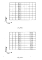
- Fig.3-1a, Fig.3-1b and Fig.3-1c are three schematic diagrams of this approach respectively;
- a pilot symbol can be modulated and mapped over the same sub-carrier of at least one OFDM symbol in a repeat data element block
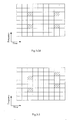
- Fig.3-2a , Fig.3-2b , Fig.3-2c and Fig.3-2d are four schematic diagrams of this approach respectively;
- a pilot symbol can be modulated and mapped over different sub-carriers of a plurality of OFDM symbol in a repeat data element block
- Fig.3-3 is a schematic diagram of this approach.
- a pilot symbol modulated and mapped into a repeat data element block can be a common or dedicated pilot symbol.
- a common pilot symbol is for channel estimation by all users in a cell, there is no need to weight and repeatedly spread the common pilot symbol. Since a dedicated pilot symbol is for channel estimation by a specific user, the dedicated pilot symbol shall be weighted and repeatedly spread, so corresponding spread dedicated pilot symbols shall be modulated and mapped into respective repeat data element blocks.
- a weight factor sequence used for weighting and repeatedly spreading a dedicated pilot symbol shall be the weight factor sequence used for a corresponding data symbol.
- a repeat factor of a data symbol M is four and a selected weight factor sequence includes four weight factors (C 1 , C 2 , C 3 and C 4 ), then a dedicated pilot symbol can be weighted and repeatedly spread also by that weight factor sequence.
- the dedicated pilot symbol is repeated to obtain four dedicated pilot symbols according to the repeat factor.
- One of the dedicated pilot symbols can be multiplied by C 1 to obtain a first spread dedicated pilot symbols
- one of the dedicated pilot symbols can be multiplied by C 2 to obtain a second spread dedicated pilot symbol
- one of the dedicated pilot symbols can be multiplied by C 3 to obtain a third spread dedicated pilot symbol
- one of the dedicated pilot symbol can be multiplied by C 4 to obtain a fourth spread dedicated pilot symbol.
- the first spread dedicated pilot symbol and the first spread data symbol are modulated and mapped into the same corresponding BRB to obtain a first repeat data element block;
- the second spread dedicated pilot symbol and the second spread data symbol are modulated and mapped into the same corresponding BRB to obtain a second repeat data element block;
- the third spread dedicated pilot symbol and the third spread data symbol are modulated and mapped into the same corresponding BRB to obtain a third repeat data element block;
- the fourth spread dedicated pilot symbol and the fourth spread data symbol are modulated and mapped into the same corresponding BRB to obtain a fourth repeat data element block.
- a corresponding transmitted signal When a pilot symbol modulated and mapped in to a repeat data element block is a common pilot symbol, a corresponding transmitted signal generally is a downlink signal.
- the network side determines a BRBG and a weight factor sequence for transmission of a data symbol are and then notifies in advance to respective User Equipments (UE) about information on the BRBG, information on the weight factor sequence, pilot configuration information and other relevant control information through broadcast or control channel so that the respective UEs can receive repeat data element blocks, perform channel estimation from a common pilot symbol in the respective repeat data element blocks and weight and combine data symbols in the respective repeat data element blocks using the weight factor sequence.
- UE User Equipments
- a corresponding transmitted signal can be a downlink or uplink signal.
- the network side determines a BRBG and a weight factor sequence for transmission of a data symbol and then notifies in advance to a relevant UE about information on the BRBG, information on the weight factor sequence, pilot configuration information and other relevant control information so that the UE can receive repeat data element blocks, perform channel estimation from spread dedicated pilot symbols in the respective repeat data element blocks and weight and combine data symbols in the respective repeat data element blocks using the weight factor sequence.
- the UE can also perform an inverse operation on the spread dedicated pilot symbols in the received plurality of repeat data element blocks to derive the weight factor sequence used for weighting and repeatedly spreading the dedicated pilot symbol, i.e., the weight factor sequence used for weighting and repeatedly spreading the data symbol, and in this case, the network side may not notify in advance the weight factor sequence to the UE.
- the UE performs an inverse operation to derive the weight factor sequence in the following process:
- the received spread dedicated pilot symbols and the un-weighted dedicated pilot symbol are compared, and an inverse operation is performed according to a comparison result to derive the weight factor sequence used for weighting and repeatedly spreading the dedicated pilot symbol.
- the UE receives the respective spread dedicated pilot symbols ⁇ 1, -1, -1, 1 ⁇ and derives the un-weighted dedicated pilot symbol ⁇ 1, 1, 1, 1 ⁇ from the pilot configuration information to thereby derive the weight factor sequence (1, -1, -1, 1) for weighting and repeatedly spreading the dedicated pilot symbol ⁇ 1, 1, 1, 1 ⁇ through comparison and an inverse operation.
- pilot symbol can be modulated and mapped in the following approaches to further reduce mutual interference between the neighbor cells.
- the pilot symbol as mentioned here can be a dedicated or common pilot symbol.
- TDM Time Division Multiplexing
- Pilot symbols of two neighbor cells shall be modulated and mapped into different OFDM symbols, and the pilot symbols of the two neighbor cells do not temporally overlap and thus can be orthogonal to reduce mutual interference.
- a cell can transmit data in an OFDM symbol occupied by another cell.
- the OFDM symbol can alternatively be unused without transmission of any data to further reduce interference to the pilot symbols.
- the TDM approach is designed primarily for block-type pilots and decentralized pilots.
- Pilot symbols of two neighbor cells can be modulated and mapped into different orthogonal sub-carriers, and the pilot symbols of the two neighbor cells are orthogonal in the frequency domain and thus can reduce mutual interference.
- a cell can transmit data over a sub-carrier occupied by another cell.
- the sub-carrier can alternatively be unused without transmission of any data to further reduce interference to the pilot symbols.
- the FDM approach is designed primarily for comb-type pilots and decentralized pilots.
- pilot symbols of two neighbor cells are modulated and mapped into the same time-frequency resource location, then the pilot symbols may overlap between the cells in a synchronous system.
- Each of pilot sequences of the different cells is multiplied by one of orthogonal sequences S i to obtain a weighted pilot sequence, and mutual interference of the pilot symbols of the different cells can be reduced due to the Orthogonality of sequences S i .
- Multiple antennas shall also be considered for using a pilot symbol in a BR-OFDM system.
- multiple antennas are typically used for transmission of data in order to increase capacity of the system and thereby to improve transmission capability of the system, and a typical application is Multiple Input Multiple Output.
- antennas can be categorized into virtual and physical antennas, where the so-called virtual antennas refer to that the number of antennas at the transmission end shall be distinguished at the reception end, and the physical antennas refer to the number of real antennas used in practice for transmission of data at the transmission end.
- the respective virtual antennas shall be distinguished by separate pilots.
- the pilots of the different virtual antennas can be distinguished in the TDM, FDM or CDM approach.
- respective antennas are provided with separate pilot symbols for downlink transmission in the same cell so that the pilot symbols of the antennas are modulated and mapped into different OFDM symbols. Orthogonality is maintained by temporally non-overlapping.
- respective antennas are provided with separate pilot symbols for downlink transmission in the same cell so that the pilot symbols of the antennas are modulated and mapped over different sub-carriers. Orthogonality is maintained by frequency non-overlapping.
- pilot symbols of all antennas are modulated and mapped into the same time-frequency resource locations for downlink transmission in the same cell, but pilot symbols of respective antennas are multiplied by different orthogonal sequences to obtain orthogonal pilot symbols.
- One of the orthogonal pilot symbols can be selected for the pilot of each of the antennas so that the pilot symbols of the multiple antennas are orthogonal in the form of code division and thus channel information can be estimated from the orthogonal pilot symbols at the reception end.
- N b N bt ⁇ N bf (N bt is the number of OFDM symbols and N bf is the number of sub-carriers) in a self-contained pilot design approach
- N bt OFDM symbols all shall include pilot symbols corresponding to respective virtual antennas in a block-type pilot design
- N bf sub-carriers all shall include pilot symbols corresponding to respective virtual antennas in a comb-type Pilot design
- N bt OFDM symbols or N bf sub-carriers shall include pilot symbols corresponding to respective virtual antennas in a decentralized pilot design.
- the pilot symbols can be multiplexed in the TDM, FDM or CDM approach.
- Fig.4 illustrates a decentralized pilot design of 2 ⁇ 2 MIMO.
- a BRB illustrated in Fig.4 includes four OFDM symbols and four sub-carriers, i.e., sixteen time-frequency resource locations.
- Four pilot symbols are modulated and mapped respectively into the sixteen time-frequency resource locations of the BRB to occupy two sub-carriers in total of two OFDM symbols.
- the density of pilot symbols in the frequency domain is the same as that of single antennas. Since pilot symbols are modulated and mapped into two OFDM symbols, the pilot symbol 1 can be selected as the pilot symbol of the antenna 1, and the pilot symbol 2 can be selected as the pilot symbol of the antenna 2.
- the pilot symbols in the two OFDM symbols can also be multiplied by orthogonal sequence with a length of 2 to distinguish the antennas 1 and 2 by the different orthogonal sequences.
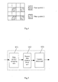
- the invention further proposes a corresponding signal transmission device based upon the foregoing signal transmission method, and Fig.5 is a schematic diagram of the device.
- the device includes a data symbol spreading unit S51, a repeat data element block unit S52 and a transmission unit S53.
- the data symbol spreading unit S51 weights and repeatedly spreads the data symbols to be transmitted into spread data symbols of the respective data symbols.
- the data symbol spreading unit S51 can weight and repeatedly spread the data symbols to be transmitted with a preconfigured RF. Moreover, a plurality of weight factor sequences can be preconfigured for a repeat factor.
- the weight factor sequence can also be referred to as Repeat Code (RC) sequence.
- Each weight factor sequence corresponding to a repeat factor includes weight factors, the number of the weight factors is the repeat factor. If the repeat factor is N, then each weight factor sequence corresponding to the repeat factor includes N weight factor.
- the preconfigured repeat factor is assumed as N, and during weighting and repeatedly spreading of a data symbol M to be transmitted, the data symbol spreading unit S51 firstly repeats the data symbol M to be transmitted by the preconfigured repeat factor to obtain N data symbols M to be transmitted. Then, the data symbol spreading unit S51 selects an available weight factor sequence from a weight factor sequence group corresponding to the repeat factor.
- the available weight factor sequence as mentioned here refers to a weight factor sequence which has not been allocated to another user.
- the data symbol spreading unit S51 can multiply one of the N data symbols to be transmitted obtained by repeating by one of the weight factors in the selected weight factor sequence to obtain a weighted data symbol.
- the N data symbols to be transmitted obtained by repeating can be multiplied respectively by the N weight factors in the selected weight factor sequence to obtain N weighted data symbols to thereby weight and repeatedly spread the data symbol M to be transmitted, where each weighted data symbol can be regarded as a spread data symbol of the data symbol M to be transmitted.
- the repeat factor is four and the selected weight factor sequence includes four weight factors (C 1 , C 2 , C 3 and C 4 ).
- the data symbol M is repeated to obtain four data symbols M; and one of the data symbols M can be multiplied by C 1 to obtain a first spread data symbol, one of the data symbols M can be multiplied by C 2 to obtain a second spread data symbol, one of the data symbols M can be multiplied by C 3 to obtain a third spread data symbol, and one of the data symbols M can be multiplied by C 4 to obtain a fourth spread data symbol.
- the data symbol spreading unit S51 can divide the plurality of data symbols into a data symbol group. Then, the respective data symbols in the data symbol group can be weighted and repeatedly spread in unit of group to obtain spread data symbols of the respective data symbols in unit of group, which are referred to as spread data symbol groups.
- a process of weighting and repeatedly spreading the respective data symbols in the data symbols group is the same as that of weighting and repeatedly spreading a single data symbol, and repeated descriptions thereof will be omitted here.
- the repeat data element block unit S52 can modulate and map the spread data symbols of the respective data symbols, which are obtained by the data symbol spreading unit S51, and a pilot symbol into specified time-frequency locations in respective corresponding BRBs to obtain respective corresponding repeat data element blocks. Then, the transmission unit S53 transmits the respective repeat data element blocks obtained by the repeat data element block unit S52.
- pilot symbol modulated and mapped into a repeat data element block by the repeat data element block unit S52 can be a common or dedicated pilot symbol.
- a common pilot symbol is for channel estimation by all users in a cell, there is no need to weight and repeatedly spread the common pilot symbol. Since a dedicated pilot symbol is for channel estimation by a specific user, the dedicated pilot symbol shall be weighted and repeatedly spread, corresponding spread dedicated pilot symbols shall be modulated and mapped into respective repeat data element blocks. In this case, the device illustrated in Fig.5 shall further include a pilot symbol spreading unit.
- the pilot symbol spreading unit is adapted to multiply a dedicated pilot symbol by respective weight factors in a weight factor sequence to weight and repeatedly spread the dedicated pilot symbol to obtain respective spread dedicated pilot symbols.
- a weight factor sequence used for weighting and repeatedly spreading a dedicated pilot symbol shall be the weight factor sequence used for a corresponding data symbol.
- a repeat factor of a data symbol M is four and a selected weight factor sequence includes four weight factors (C 1, C 2 , C 3 and C 4 ), then a dedicated pilot symbol can be weighted and repeatedly spread also by that weight factor sequence.
- the pilot symbol spreading unit repeats the dedicated pilot symbol by the repeat factor to obtain four dedicated pilot symbols. Then, the pilot symbol spreading unit can multiply one of the dedicated pilot symbols by C 1 to obtain a first spread dedicated pilot symbols, multiply one of the dedicated pilot symbol by C 2 to obtain a second spread dedicated pilot symbol, multiply one of the dedicated pilot symbols by C 3 to obtain a third spread dedicated pilot symbol, and multiply one of the dedicated pilot symbol by C 4 to obtain a fourth spread dedicated pilot symbol.
- the repeat data element block unit S52 modulates and maps the first spread dedicated pilot symbol and the first spread data symbol into the same corresponding BRB to obtain a first repeat data element block; the repeat data element block unit S52 modulates and maps the second spread dedicated pilot symbol and the second spread data symbol into the same corresponding BRB to obtain a second repeat data element block; the repeat data element block unit S52 modulates and maps the third spread dedicated pilot symbol and the third spread data symbol into the same corresponding BRB to obtain a third repeat data element block; and the repeat data element block unit S52 modulates and maps the fourth spread dedicated pilot symbol and the fourth spread data symbol into the same corresponding BRB to obtain a fourth repeat data element block.
- a state and a channel response of a radio channel can be estimated accurately from the pilot symbols in the repeat data element blocks by the reception end upon reception of the repeat data element blocks to thereby detect and demodulate properly the received signal.
- a pilot symbol can be modulated and mapped over at least one sub-carrier of the same OFDM symbol in a repeat data element block
- Fig.3-1a, Fig.3-1b and Fig.3-1c are three schematic diagrams of this approach respectively;
- a pilot symbol can be modulated and mapped over the same sub-carrier of at least one OFDM symbol in a repeat data element block
- Fig.3-2a , Fig.3-2b , Fig.3-2c and Fig.3-2d are four schematic diagrams of this approach respectively;
- a pilot symbol can be modulated and mapped over different sub-carriers of a plurality of OFDM symbol in a repeat data element block
- Fig.3-3 is a schematic diagram of this approach.
- the method and device according to the invention can be applicable to both an existing base station (Node B), a Radio network Controller (RNC) or a user terminal and an evolved base station (eNode B) and user terminal as well as some network side devices functionally similar to a base station and a user terminal in a future communication system.
- Node B Node B
- RNC Radio network Controller
- eNode B evolved base station
- the respective illustrative units described in connection with the embodiments disclosed here can be implemented or performed with a general processor, a Digital Signal Processor (DSP), an Application Specific Integrated Circuit (ASIC), a Field Programmable Gate Array (FPGA) or other programmable logic devices, discrete gate or transistor logic, discrete hardware component or any combination thereof.
- the general processor may be a microprocessor, but in another case, the processor can be any conventional processor, controller, micro-controller or state machine.
- the processor can alternatively be implemented as a combination of computing devices, e.g., a combination of a DSP and a microprocessor, a plurality of microprocessors, one or more microprocessors integrated with a DSP core or any other such a structure.
- the steps of the method described in connection with the embodiments disclosed above can be embodied directly as hardware, a software module executed by a processor or a combination of both.
- the software module can reside in a RAM memory, a flash memory, a ROM memory, an EPROM memory, an EEPROM memory, a register, a hard disk, a removable disk, a CD-ROM or any other storage medium well known in the art.
- a typical storage medium is coupled with a processor so that the processor can read information from and write information into the storage medium.
- the storage medium is a constituent part of the processor.
- the processor and the storage medium can be stored in an ASIC and the ASIC possibly residing in a user station.
- the processor and the storage medium can exist as discrete components in a user station.
Landscapes
- Engineering & Computer Science (AREA)
- Signal Processing (AREA)
- Computer Networks & Wireless Communication (AREA)
- Mobile Radio Communication Systems (AREA)
Abstract
Description
- This application claims priority to Chinese Patent Application No.
200710175758.9 - The present invention relates to the field of Orthogonal Frequency Division Multiplexing (OFDM) radio mobile communications and in particular to a signal transmission method and device.
- OFDM will be widely applied in future communication systems as a basic technique for air interfaces of the systems.
- A process of transmitting a signal through OFDM involves:
- a. Data to be transmitted is modulated and segmented into a block of data symbols; and
- b. the block of generated data symbols and a pilot symbol (a common or Dedicated pilot symbol) are modulated and mapped into specified time-frequency locations of a Physical Resource Block (PRB) to obtain a Data Block (DB) corresponding to the data to be transmitted; and
- c. The data block is transmitted.
- For transmission of the signal through OFDM, a channel resource is a two dimensional structures of time-frequency and can be divided into one or more PRBs.
Fig. 1 is a schematic diagram of a PRB which occupies a part of the channel resource. The PRB includes NT consecutive OFDM symbols in the time domain and NF consecutive orthogonal sub-can-iers in the frequency domain. The PRB totally includes NT×NF time-frequency locations. - As can be apparent, data of different users can be transmitted over different orthogonal sub-carriers in an OFDM symbol during transmission of the signal through OFDM to thereby achieve multiplexing and multiple-access of users.
- For an OFDM system, there is no multiple access interference in a cell. However in a same frequency network, users of neighbor cells may cause interference to each other if signals are transmitted at the same time-frequency locations. Especially if a user at the edge of a cell is closer to another neighbor cell, then an interference signal from another user in the neighbor cell may be strong so that the user at the edge of the cell may suffer from a degraded quality of communication.
- In view of this, a technical problem solved by the invention is to provide a signal transmission method and device to reduce interference between users of neighbor cells in a same frequency network using an OFDM technique and thus improve communication quality of a user at the edge of a cell.
- In order to attain this object, technical solutions of the invention are as follows:
- A signal transmission method includes:
- weighting and repeatedly spreading respective data symbols to be transmitted to obtain spread data symbols of the respective data symbols;
- modulating and mapping the spread data symbols of the respective data symbols and a pilot symbol into specified time-frequency locations in respective corresponding Block Repeat resource Blocks, BRBs, to obtain respective corresponding repeat data element blocks; and
- transmitting the respective repeat data element blocks,
- Preferably, the data symbols to be transmitted are weighted and repeatedly spread by a Repeat Factor RF.
- In some embodiments, the data symbols are repeated by the RF, and an available weight factor sequence is selected from a group of weight factor sequences corresponding to the RF; and the respective data symbols obtained by repeating are multiplied by respective weight factors in the selected weight factor sequence to weight and repeatedly spread the data symbols.
- In some embodiments, the pilot symbol is a spread dedicated pilot symbol.
- In some embodiments, the dedicated pilot symbol is weighted and repeatedly spread by the respective weight factors in the weight factor sequence to obtain respective spread dedicated pilot symbols.
- Preferably, the dedicated pilot symbol is repeated by the RF; and the respective dedicated pilot symbols obtained by repeating are multiplied by the respective weight factors in the weight factor sequence to weight and repeatedly spread the dedicated pilot symbol.
- In some embodiments, the method further includes: comparing the respective spread dedicated pilot symbols in the respective repeat data element blocks with the un-weighted dedicated pilot symbol, by a receiving terminal, upon reception of the respective repeat data element blocks; and performing an inverse operation to derive the weight factor sequence for weighting and repeatedly spreading the dedicated pilot symbol.
- In some embodiments, the pilot symbol is a common pilot symbol.
- In some embodiments, pilot symbols of users of neighbor cells are modulated and mapped into non-overlapping time-frequency resource locations in BRBs.
- In some embodiments, sequences used by pilot symbols of users of neighbor cells are orthogonal each other.
- In some embodiments, pilot symbols transmitted over different antennas are modulated and mapped into non-overlapping time-frequency resource locations in BRBs.
- In some embodiments, sequences used by pilot symbols transmitted over different antennas are orthogonal each other.
- The invention further provides a corresponding signal transmission device including:
- a data symbol spreading unit adapted to weight and repeatedly spread respective data symbols to be transmitted to obtain spread data symbols of the respective data symbols;
- a repeat data element block unit adapted to modulate and map the spread data symbols, which are obtained by the data symbol spreading unit, and a pilot symbol into specified time-frequency locations in respective corresponding Block Repeat resource Blocks, BRBs, to obtain respective corresponding repeat data element blocks;; and
- a transmission unit adapted to transmit the respective repeat data element blocks obtained by the repeat data element block unit.
- Preferably, the data symbol spreading unit weights and repeatedly spreads the data symbols to be transmitted by a Repeat Factor, RF.
- In some embodiments, the data symbol spreading unit includes: a module adapted to repeat the data symbols by the RF and to select an available weight factor sequence from a group of weight factor sequences corresponding to the RF; and a module adapted to multiply the respective data symbols obtained by repeating by respective weight factors in the selected weight factor sequence to weight and repeatedly spread the data symbols.
- In some embodiments, the pilot symbol is a spread dedicated pilot symbol.
- In some embodiments, the device further includes: a pilot symbol spreading unit adapted to weight and repeatedly spread the dedicated pilot symbol using the respective weight factors in the weight factor sequence to obtain respective spread dedicated pilot symbols.
- Preferably, the pilot symbol spreading unit includes: a module adapted to repeat the dedicated pilot symbol by the RF; and a module adapted to multiply the respective dedicated pilot symbols obtained by repeating by the respective weight factors in the weight factor sequence to weight and repeatedly spread the dedicated pilot symbol.
- In some embodiments, the pilot symbol is a common pilot symbol.
- In the invention, data of different users occupying the same time-frequency locations can be weighted and repeatedly spread by using different weight factor sequences to obtain different repeat data element blocks. In a same frequency network, if a user at the edge of a cell receives a signal transmitted from a user of an neighbor cell, the respective repeat data element block occupying the same time-frequency locations can be separated by the different weight factor sequences to thereby reduce interference between the users of the neighbor cells and improve communication quality of the user at the edge of the cell. Moreover, after the pilot symbol is modulated and mapped into the repeat data element blocks, a state and a channel response of a radio channel can be estimated accurately from the pilot symbol in the repeat data element blocks by the reception end upon reception of the repeat data element blocks to thereby detect and demodulate properly the received signal. The use of the technical solutions of the invention can achieve effective, reliable and variable-rate transmission of information over a radio communication channel and also multiplexing and multiple access of radio communication channel resources. An application of the method and device in a radio mobile cellular system can conveniently implement a same frequency network and improve the capacity and performance of the system. The proposed method can address well the issues of allocation and scheduling of resources and coordination and control of interference (including inter-cell and intra-cell interference) in radio communication to thereby improve greatly the capacity and performance.
-
Fig. 1 is a schematic diagram of a PRB using OFDM in the prior art; -
Fig.2 is a flow chart of a signal transmission method according to an embodiment of the invention; -
Fig.3-1a, Fig.3-1b Fig.3-1c, Fig.3-2a ,Fig.3-2b, Fig.3-2c ,Fig.3-2d and Fig.3-3 are schematic diagram of modulating and mapping a pilot symbol into a repeat data element block according to an embodiment of the invention; -
Fig.4 is a schematic diagram of a decentralized pilot design of an MIMO antenna according to an embodiment of the invention; and -
Fig.5 is a schematic structural diagram of a signal transmission device according to an embodiment of the invention. - The invention proposes the idea of a "block repeat division multiple access", a solution of which is a new efficient multiple access solution. Block Repeat (BR) based information transmission can be referred to as block repeat transmission. Block repeat based multiplexing can be referred to as Block Repeat Division Multiplexing (BRDM). Block repeat based multiple-access can be referred to as Block Repeat Division Multiple-Access (BRDMA). A block repeat division multiple-access solution combined with OFDM can be referred to as Block Repeat-Orthogonal Frequency Division Multiplexing (BR-OFDM) and Block Repeat-Orthogonal Frequency Division Multiple-Access (BR-OFDMA).
- The invention will be detailed below with reference to the drawings and embodiments to make the invention more apparent to those skilled in the art.
- Reference is made to
Fig.2 illustrating a flow chart of a signal transmission method according to an embodiment of the invention. - In
step 21, data to be transmitted is modulated and segmented into respective data symbols; and - In
step 22, the respective data symbols are weighted and repeatedly spread to obtain spread data symbols of the respective data symbols. - The data to be transmitted can be weighted and repeatedly spread with a preconfigured Repeat Factor (RF), i.e., the number of times that the data symbols are repeated. Moreover, a set of weight factor sequences can be preconfigured for a repeat factor, and the set of weight factor sequences can be referred to as a weight factor sequence group corresponding to the repeat factor. The weight factor sequence can also be referred to as Repeat Codes (RC) sequence.
- Each weight factor sequence corresponding to a repeat factor includes weight factors, the number of the weight factors is the repeat factor. If the repeat factor is N, then each weight factor sequence corresponding to the repeat factor includes N weight factors.
- During weighting and repeatedly spreading a data symbol M to be transmitted, the preconfigured repeat factor is assumed as N, firstly the data symbol M to be transmitted is repeated to obtain N data symbols M to be transmitted according to the preconfigured repeat factor. Then an available weight factor sequence is selected from the weight factor sequence group corresponding to the repeat factor. The available weight factor sequence as mentioned here refers to a weight factor sequence which has not been allocated to another user.
- One of the N data symbols to be transmitted obtained by repeating can be multiplied by one of the weight factors in the selected weight factor sequence to obtain a weighted data symbol. The N data symbols to be transmitted obtained by repeating can be multiplied respectively by the N weight factors in the selected weight factor sequence to obtain N weighted data symbols to thereby weight and repeatedly spread the data symbol M to be transmitted, where each weighted data symbol can be regarded as a spread data symbol of the data symbol M to be transmitted.
- It is assumed that the repeat factor is four and the selected weight factor sequence includes four weight factors (C1, C2, C3 and C4). The data symbol M is repeated to obtain four data symbols M; and one of the data symbols M can be multiplied by C1 to obtain a first spread data symbol, one of the data symbols M can be multiplied by C2 to obtain a second spread data symbol, one of the data symbols M can be multiplied by C3 to obtain a third spread data symbol, and one of the data symbols M can be multiplied by C4 to obtain a fourth spread data symbol.
- When there is a block of data symbols to be transmitted, the block of data symbols can be divided into a data symbol group. Then, the respective data symbols in the data symbol group can be weighted and repeatedly spread in unit of group to obtain spread data symbols of the respective data symbols in unit of group, which are referred to as spread data symbol groups. A process of weighting and repeatedly spreading the respective data symbols in the data symbol group is the same as that of weighting and repeatedly spreading a single data symbol, and repeated descriptions thereof will be omitted here.
- After the spread data symbols of the respective data symbols is obtained, the spread data symbols of the respective data symbols and a pilot symbol are modulated and mapped into specified time-frequency locations in respective corresponding Block Repeat Resource Blocks (BRB) to obtain respective corresponding repeat data element blocks in the
step 23. Then, the respective repeat data element blocks are transmitted in thestep 24. - In a BR-OFDM system, a BRB is an elementary physical resource unit including a block of consecutive OFDM symbols in the time domain and also a block of consecutive orthogonal sub-carriers in the frequency domain. The size of a BRB shall be predetermined. A group of several BRBs can be referred to as a Block Repeat resource Block Group (BRBG). The respective BRBs constituting the BRBG may or may not be consecutive in the time and/or frequency domain. A BRBG in which respective constituent BRBs are consecutive in the time domain can be referred to as a time-consecutive BRBG (as illustrated in
Fig.3-1 ), and a BRBG in which respective constituent BRBs are consecutive in the frequency domain can be referred to as a frequency-consecutive BRBG (as illustrated inFig.3-2 ). A BRBG in which respective constituent BRBs are consecutive in both the time and frequency domains can be referred to as a time- and frequency-consecutive BRBG (as illustrated inFig.3-3 ). - During repeat modulation, respective spread data symbol groups of a data symbols group shall be modulated and mapped into respective BRBs in the same BRBG with each of the spread data symbol groups corresponding to one of the BRBs. A pilot symbol shall also be modulated and mapped into specific time-frequency locations in the respective BRBs.
- As can be apparent, the number of BRBs included in a BRBG is the repeat factor of a data symbol group. For scheduling of time-frequency resources, the time-frequency resources can be allocated by BRBG to users according to service rate and quality demands of the users, for example, one or more BRBGs can be allocated to a user. Repeat factors of BRBGs allocated to different users may be identical or different.
- A spread data symbol group and a pilot symbol can be modulated and mapped into a BRB to obtain a repeat data element block. As can be apparent, the repeat data element block refers to a block of time-frequency resources into which the spread data symbol group and the pilot symbol are modulated and mapped.
- As can be apparent, after the pilot symbol is modulated and mapped into the repeat data element blocks, a state and a channel response of a radio channel can be estimated accurately from the pilot symbol in the repeat data element blocks by the reception end upon reception of the repeat data element blocks to thereby detect and demodulate properly the received signal.
- A pilot symbol can be modulated and mapped into a repeat data element block in the following approaches but will not be limited thereto:
- a. A pilot symbol can be modulated and mapped over at least one sub-carrier of the same OFDM symbol in a repeat data element block, and
Fig.3-1a, Fig.3-1b andFig.3-1c are three schematic diagrams of this approach respectively; - b. A pilot symbol can be modulated and mapped over the same sub-carrier of at least one OFDM symbol in a repeat data element block, and
Fig.3-2a ,Fig.3-2b ,Fig.3-2c andFig.3-2d are four schematic diagrams of this approach respectively; and - c. A pilot symbol can be modulated and mapped over different sub-carriers of a plurality of OFDM symbol in a repeat data element block, and
Fig.3-3 is a schematic diagram of this approach. - It shall be noted that a pilot symbol modulated and mapped into a repeat data element block can be a common or dedicated pilot symbol.
- Since a common pilot symbol is for channel estimation by all users in a cell, there is no need to weight and repeatedly spread the common pilot symbol. Since a dedicated pilot symbol is for channel estimation by a specific user, the dedicated pilot symbol shall be weighted and repeatedly spread, so corresponding spread dedicated pilot symbols shall be modulated and mapped into respective repeat data element blocks.
- A weight factor sequence used for weighting and repeatedly spreading a dedicated pilot symbol shall be the weight factor sequence used for a corresponding data symbol.
- If a repeat factor of a data symbol M is four and a selected weight factor sequence includes four weight factors (C1, C2, C3 and C4), then a dedicated pilot symbol can be weighted and repeatedly spread also by that weight factor sequence.
- Firstly, the dedicated pilot symbol is repeated to obtain four dedicated pilot symbols according to the repeat factor. One of the dedicated pilot symbols can be multiplied by C1 to obtain a first spread dedicated pilot symbols, one of the dedicated pilot symbols can be multiplied by C2 to obtain a second spread dedicated pilot symbol, one of the dedicated pilot symbols can be multiplied by C3 to obtain a third spread dedicated pilot symbol, and one of the dedicated pilot symbol can be multiplied by C4 to obtain a fourth spread dedicated pilot symbol.
- After the four spread dedicated pilot symbols are obtained, the first spread dedicated pilot symbol and the first spread data symbol are modulated and mapped into the same corresponding BRB to obtain a first repeat data element block; the second spread dedicated pilot symbol and the second spread data symbol are modulated and mapped into the same corresponding BRB to obtain a second repeat data element block; the third spread dedicated pilot symbol and the third spread data symbol are modulated and mapped into the same corresponding BRB to obtain a third repeat data element block; and the fourth spread dedicated pilot symbol and the fourth spread data symbol are modulated and mapped into the same corresponding BRB to obtain a fourth repeat data element block.
- When a pilot symbol modulated and mapped in to a repeat data element block is a common pilot symbol, a corresponding transmitted signal generally is a downlink signal.
- In case of transmission of a downlink signal, the network side determines a BRBG and a weight factor sequence for transmission of a data symbol are and then notifies in advance to respective User Equipments (UE) about information on the BRBG, information on the weight factor sequence, pilot configuration information and other relevant control information through broadcast or control channel so that the respective UEs can receive repeat data element blocks, perform channel estimation from a common pilot symbol in the respective repeat data element blocks and weight and combine data symbols in the respective repeat data element blocks using the weight factor sequence.
- When a pilot symbol modulated and mapped into a repeat data element block is a dedicated pilot symbol, a corresponding transmitted signal can be a downlink or uplink signal.
- In case of transmission of a downlink signal, the network side determines a BRBG and a weight factor sequence for transmission of a data symbol and then notifies in advance to a relevant UE about information on the BRBG, information on the weight factor sequence, pilot configuration information and other relevant control information so that the UE can receive repeat data element blocks, perform channel estimation from spread dedicated pilot symbols in the respective repeat data element blocks and weight and combine data symbols in the respective repeat data element blocks using the weight factor sequence.
- The UE can also perform an inverse operation on the spread dedicated pilot symbols in the received plurality of repeat data element blocks to derive the weight factor sequence used for weighting and repeatedly spreading the dedicated pilot symbol, i.e., the weight factor sequence used for weighting and repeatedly spreading the data symbol, and in this case, the network side may not notify in advance the weight factor sequence to the UE.
- The UE performs an inverse operation to derive the weight factor sequence in the following process:
- The received spread dedicated pilot symbols and the un-weighted dedicated pilot symbol are compared, and an inverse operation is performed according to a comparison result to derive the weight factor sequence used for weighting and repeatedly spreading the dedicated pilot symbol.
- For example, the UE receives the respective spread dedicated pilot symbols {1, -1, -1, 1} and derives the un-weighted dedicated pilot symbol {1, 1, 1, 1} from the pilot configuration information to thereby derive the weight factor sequence (1, -1, -1, 1) for weighting and repeatedly spreading the dedicated pilot symbol {1, 1, 1, 1} through comparison and an inverse operation.
- It shall be noted that interference between neighbor cells may degrade the performance of a cellular mobile communication system. Therefore, both the design of a dedicated pilot and that of a common pilot shall be considered carefully for channel estimation in order to reduce interference between neighbor cells. For transmission of a signal between neighbor cells, a pilot symbol can be modulated and mapped in the following approaches to further reduce mutual interference between the neighbor cells. The pilot symbol as mentioned here can be a dedicated or common pilot symbol.
- In the approach of Time Division Multiplexing (TDM):
- Pilot symbols of two neighbor cells shall be modulated and mapped into different OFDM symbols, and the pilot symbols of the two neighbor cells do not temporally overlap and thus can be orthogonal to reduce mutual interference. A cell can transmit data in an OFDM symbol occupied by another cell.
- The OFDM symbol can alternatively be unused without transmission of any data to further reduce interference to the pilot symbols.
- The TDM approach is designed primarily for block-type pilots and decentralized pilots.
- In the approach of Frequency Division Multiplexing (FDM):
- Pilot symbols of two neighbor cells can be modulated and mapped into different orthogonal sub-carriers, and the pilot symbols of the two neighbor cells are orthogonal in the frequency domain and thus can reduce mutual interference. A cell can transmit data over a sub-carrier occupied by another cell.
- The sub-carrier can alternatively be unused without transmission of any data to further reduce interference to the pilot symbols.
- The FDM approach is designed primarily for comb-type pilots and decentralized pilots.
- In the approach of Code Division Multiplexing (CDM):
- If pilot symbols of two neighbor cells are modulated and mapped into the same time-frequency resource location, then the pilot symbols may overlap between the cells in a synchronous system. At this time, a orthogonal sequence set S = {S1, S2, ......, Sk} including k orthogonal sequences can be arranged, each of the orthogonal sequence is Si = [Si_1, Si_2, ......, Si_m], 1 ≤ i ≤ k. Each of pilot sequences of the different cells is multiplied by one of orthogonal sequences Si to obtain a weighted pilot sequence, and mutual interference of the pilot symbols of the different cells can be reduced due to the Orthogonality of sequences Si.
- As can be apparent, the three approaches of modulating and mapping a pilot symbol between neighbor cells, i.e., TDM, FDM and CDM, can be used alone or in combination, and repeated descriptions thereof will be omitted here.
- Multiple antennas shall also be considered for using a pilot symbol in a BR-OFDM system. In an existing broadcast communication system, multiple antennas are typically used for transmission of data in order to increase capacity of the system and thereby to improve transmission capability of the system, and a typical application is Multiple Input Multiple Output.
- In MIMO, antennas can be categorized into virtual and physical antennas, where the so-called virtual antennas refer to that the number of antennas at the transmission end shall be distinguished at the reception end, and the physical antennas refer to the number of real antennas used in practice for transmission of data at the transmission end. In order to be capable of accurately detecting and demodulating data transmitted over different antennas, information on channels for transmission of data over the respective virtual antennas from the transmission end to the reception end shall be estimated separately at the reception end. Therefore, the respective virtual antennas shall be distinguished by separate pilots. The pilots of the different virtual antennas can be distinguished in the TDM, FDM or CDM approach.
- For pilot symbol modulation and mapping in the TDM approach, respective antennas are provided with separate pilot symbols for downlink transmission in the same cell so that the pilot symbols of the antennas are modulated and mapped into different OFDM symbols. Orthogonality is maintained by temporally non-overlapping.
- For pilot symbol modulation and mapping in the FDM approach, respective antennas are provided with separate pilot symbols for downlink transmission in the same cell so that the pilot symbols of the antennas are modulated and mapped over different sub-carriers. Orthogonality is maintained by frequency non-overlapping.
- For pilot symbol modulation and mapping in the CDM approach, pilot symbols of all antennas are modulated and mapped into the same time-frequency resource locations for downlink transmission in the same cell, but pilot symbols of respective antennas are multiplied by different orthogonal sequences to obtain orthogonal pilot symbols. One of the orthogonal pilot symbols can be selected for the pilot of each of the antennas so that the pilot symbols of the multiple antennas are orthogonal in the form of code division and thus channel information can be estimated from the orthogonal pilot symbols at the reception end.
- For a BR-OFDM system, if an elementary block can be represented as Nb = Nbt × Nbf (Nbt is the number of OFDM symbols and Nbf is the number of sub-carriers) in a self-contained pilot design approach, then Nbt OFDM symbols all shall include pilot symbols corresponding to respective virtual antennas in a block-type pilot design, Nbf sub-carriers all shall include pilot symbols corresponding to respective virtual antennas in a comb-type Pilot design, or Nbt OFDM symbols or Nbf sub-carriers shall include pilot symbols corresponding to respective virtual antennas in a decentralized pilot design. The pilot symbols can be multiplexed in the TDM, FDM or CDM approach.
-
Fig.4 illustrates a decentralized pilot design of 2×2 MIMO. A BRB illustrated inFig.4 includes four OFDM symbols and four sub-carriers, i.e., sixteen time-frequency resource locations. Four pilot symbols are modulated and mapped respectively into the sixteen time-frequency resource locations of the BRB to occupy two sub-carriers in total of two OFDM symbols. The density of pilot symbols in the frequency domain is the same as that of single antennas. Since pilot symbols are modulated and mapped into two OFDM symbols, thepilot symbol 1 can be selected as the pilot symbol of theantenna 1, and thepilot symbol 2 can be selected as the pilot symbol of theantenna 2. The pilot symbols in the two OFDM symbols can also be multiplied by orthogonal sequence with a length of 2 to distinguish theantennas - The invention further proposes a corresponding signal transmission device based upon the foregoing signal transmission method, and
Fig.5 is a schematic diagram of the device. The device includes a data symbol spreading unit S51, a repeat data element block unit S52 and a transmission unit S53. - After a transmission end device modulates and segments data to be transmitted into data symbols, the data symbol spreading unit S51 weights and repeatedly spreads the data symbols to be transmitted into spread data symbols of the respective data symbols.
- The data symbol spreading unit S51 can weight and repeatedly spread the data symbols to be transmitted with a preconfigured RF. Moreover, a plurality of weight factor sequences can be preconfigured for a repeat factor. The weight factor sequence can also be referred to as Repeat Code (RC) sequence.
- Each weight factor sequence corresponding to a repeat factor includes weight factors, the number of the weight factors is the repeat factor. If the repeat factor is N, then each weight factor sequence corresponding to the repeat factor includes N weight factor.
- The preconfigured repeat factor is assumed as N, and during weighting and repeatedly spreading of a data symbol M to be transmitted, the data symbol spreading unit S51 firstly repeats the data symbol M to be transmitted by the preconfigured repeat factor to obtain N data symbols M to be transmitted. Then, the data symbol spreading unit S51 selects an available weight factor sequence from a weight factor sequence group corresponding to the repeat factor. The available weight factor sequence as mentioned here refers to a weight factor sequence which has not been allocated to another user.
- The data symbol spreading unit S51 can multiply one of the N data symbols to be transmitted obtained by repeating by one of the weight factors in the selected weight factor sequence to obtain a weighted data symbol. The N data symbols to be transmitted obtained by repeating can be multiplied respectively by the N weight factors in the selected weight factor sequence to obtain N weighted data symbols to thereby weight and repeatedly spread the data symbol M to be transmitted, where each weighted data symbol can be regarded as a spread data symbol of the data symbol M to be transmitted.
- It is assumed that the repeat factor is four and the selected weight factor sequence includes four weight factors (C1, C2, C3 and C4). The data symbol M is repeated to obtain four data symbols M; and one of the data symbols M can be multiplied by C1 to obtain a first spread data symbol, one of the data symbols M can be multiplied by C2 to obtain a second spread data symbol, one of the data symbols M can be multiplied by C3 to obtain a third spread data symbol, and one of the data symbols M can be multiplied by C4 to obtain a fourth spread data symbol.
- When there is a plurality of data symbols to be transmitted, the data symbol spreading unit S51 can divide the plurality of data symbols into a data symbol group. Then, the respective data symbols in the data symbol group can be weighted and repeatedly spread in unit of group to obtain spread data symbols of the respective data symbols in unit of group, which are referred to as spread data symbol groups. A process of weighting and repeatedly spreading the respective data symbols in the data symbols group is the same as that of weighting and repeatedly spreading a single data symbol, and repeated descriptions thereof will be omitted here.
- After obtaining the spread data symbols of the respective data symbols, the repeat data element block unit S52 can modulate and map the spread data symbols of the respective data symbols, which are obtained by the data symbol spreading unit S51, and a pilot symbol into specified time-frequency locations in respective corresponding BRBs to obtain respective corresponding repeat data element blocks. Then, the transmission unit S53 transmits the respective repeat data element blocks obtained by the repeat data element block unit S52.
- It shall be noted that the pilot symbol modulated and mapped into a repeat data element block by the repeat data element block unit S52 can be a common or dedicated pilot symbol.
- Since a common pilot symbol is for channel estimation by all users in a cell, there is no need to weight and repeatedly spread the common pilot symbol. Since a dedicated pilot symbol is for channel estimation by a specific user, the dedicated pilot symbol shall be weighted and repeatedly spread, corresponding spread dedicated pilot symbols shall be modulated and mapped into respective repeat data element blocks. In this case, the device illustrated in
Fig.5 shall further include a pilot symbol spreading unit. - The pilot symbol spreading unit is adapted to multiply a dedicated pilot symbol by respective weight factors in a weight factor sequence to weight and repeatedly spread the dedicated pilot symbol to obtain respective spread dedicated pilot symbols.
- A weight factor sequence used for weighting and repeatedly spreading a dedicated pilot symbol shall be the weight factor sequence used for a corresponding data symbol.
- If a repeat factor of a data symbol M is four and a selected weight factor sequence includes four weight factors (C1, C2, C3 and C4), then a dedicated pilot symbol can be weighted and repeatedly spread also by that weight factor sequence.
- Firstly, the pilot symbol spreading unit repeats the dedicated pilot symbol by the repeat factor to obtain four dedicated pilot symbols. Then, the pilot symbol spreading unit can multiply one of the dedicated pilot symbols by C1 to obtain a first spread dedicated pilot symbols, multiply one of the dedicated pilot symbol by C2 to obtain a second spread dedicated pilot symbol, multiply one of the dedicated pilot symbols by C3 to obtain a third spread dedicated pilot symbol, and multiply one of the dedicated pilot symbol by C4 to obtain a fourth spread dedicated pilot symbol.
- After the pilot symbol spreading unit obtains the four spread dedicated pilot symbols, the repeat data element block unit S52 modulates and maps the first spread dedicated pilot symbol and the first spread data symbol into the same corresponding BRB to obtain a first repeat data element block; the repeat data element block unit S52 modulates and maps the second spread dedicated pilot symbol and the second spread data symbol into the same corresponding BRB to obtain a second repeat data element block; the repeat data element block unit S52 modulates and maps the third spread dedicated pilot symbol and the third spread data symbol into the same corresponding BRB to obtain a third repeat data element block; and the repeat data element block unit S52 modulates and maps the fourth spread dedicated pilot symbol and the fourth spread data symbol into the same corresponding BRB to obtain a fourth repeat data element block.
- As can be apparent, after the pilot symbol is modulated and mapped the repeat data element blocks, a state and a channel response of a radio channel can be estimated accurately from the pilot symbols in the repeat data element blocks by the reception end upon reception of the repeat data element blocks to thereby detect and demodulate properly the received signal.
- A pilot symbol can be modulated and mapped into a repeat data element block in the following approaches but will not be limited thereto:
- a. A pilot symbol can be modulated and mapped over at least one sub-carrier of the same OFDM symbol in a repeat data element block, and
Fig.3-1a, Fig.3-1b andFig.3-1c are three schematic diagrams of this approach respectively; - b. A pilot symbol can be modulated and mapped over the same sub-carrier of at least one OFDM symbol in a repeat data element block, and
Fig.3-2a ,Fig.3-2b ,Fig.3-2c andFig.3-2d are four schematic diagrams of this approach respectively; and - c. A pilot symbol can be modulated and mapped over different sub-carriers of a plurality of OFDM symbol in a repeat data element block, and
Fig.3-3 is a schematic diagram of this approach. - As can be apparent, the method and device according to the invention can be applicable to both an existing base station (Node B), a Radio network Controller (RNC) or a user terminal and an evolved base station (eNode B) and user terminal as well as some network side devices functionally similar to a base station and a user terminal in a future communication system.
- Those skilled in the art can appreciate that the respective illustrative steps of the method and units of the device described here in connection with the disclosed embodiments can be implemented in electric hardware, in software or in combination thereof. The foregoing illustrative steps and units have been described in general in term of their functions in order to illustrate clearly exchangeability between hardware and software. Whether these functions are implemented in hardware or software is dependent upon a specific application and a design constrain of implementing the system. Those skilled in the art can implement the described functions in various ways for respective specific applications, but such an implementation result shall not be construed as departing from the scope of the invention.
- The respective illustrative units described in connection with the embodiments disclosed here can be implemented or performed with a general processor, a Digital Signal Processor (DSP), an Application Specific Integrated Circuit (ASIC), a Field Programmable Gate Array (FPGA) or other programmable logic devices, discrete gate or transistor logic, discrete hardware component or any combination thereof. The general processor may be a microprocessor, but in another case, the processor can be any conventional processor, controller, micro-controller or state machine. The processor can alternatively be implemented as a combination of computing devices, e.g., a combination of a DSP and a microprocessor, a plurality of microprocessors, one or more microprocessors integrated with a DSP core or any other such a structure.
- The steps of the method described in connection with the embodiments disclosed above can be embodied directly as hardware, a software module executed by a processor or a combination of both. The software module can reside in a RAM memory, a flash memory, a ROM memory, an EPROM memory, an EEPROM memory, a register, a hard disk, a removable disk, a CD-ROM or any other storage medium well known in the art. A typical storage medium is coupled with a processor so that the processor can read information from and write information into the storage medium. Alternatively, the storage medium is a constituent part of the processor. The processor and the storage medium can be stored in an ASIC and the ASIC possibly residing in a user station. Alternatively, the processor and the storage medium can exist as discrete components in a user station.
- The disclosed embodiments have been provided so that those skilled in the art can implement or apply the invention. Various modifications to these embodiments will be obvious to those skilled in the art, and also the general principal defined here can be applicable to other embodiments without departing from the scope and spirit of the invention. The embodiments described above are merely preferred embodiments of the invention but not intended to limit the invention, and any modifications, equivalents or improvements made without departing from the spirit and principal of the invention shall come into the scope of protection of the invention.
Claims (16)
- A signal transmission method, comprising:weighting and repeatedly spreading respective data symbols to be transmitted, to obtain spread data symbols of the respective data symbols;modulating and mapping the spread data symbols of the respective data symbols and a pilot symbol into specified time-frequency locations in respective corresponding Block Repeat resource Blocks, BRBs, to obtain respective corresponding repeat data element blocks; andtransmitting the respective repeat data element blocks.
- The method according to claim 1, wherein weighting and repeatedly spreading the respective data symbols to be transmitted comprises:repeating the data symbols by a Repeat Factor, RF, and selecting an available weight factor sequence from a group of weight factor sequences corresponding to the RF; andmultiplying the respective data symbols obtained by repeating by respective weight factors in the selected weight factor sequence to weight and repeatedly spread the data symbols.
- The method according to claim 2, wherein the pilot symbol is a dedicated pilot symbol, and the method further comprises weighting and repeatedly spreading the dedicated pilot symbol using the respective weight factors in the weight factor sequence, to obtain respective spread dedicated pilot symbols.
- The method according to claim 3, further comprising:repeating the dedicated pilot symbol by the RF; andmultiplying the respective dedicated pilot symbols obtained by repeating by the respective weight factors in the weight factor sequence to weight and repeatedly spread the dedicated pilot symbol.
- The method according to claim 3, further comprising:comparing the respective spread dedicated pilot symbols in the respective repeat data element blocks with the un-weighted dedicated pilot symbol, by a receiving end device, upon reception of the respective repeat data element blocks; andperforming an inverse operation to derive the weight factor sequence for weighting and repeatedly spreading the dedicated pilot symbol.
- The method according to claim 1, wherein the pilot symbol is a common pilot symbol.
- The method according to any one of claims 1 to 6, wherein pilot symbols of users of neighbor cells are modulated and mapped into non-overlapping time-frequency resource locations in BRBs.
- The method according to any one of claims 1 to 6, wherein sequences used by pilot symbols of users of neighbor cells are orthogonal each other.
- The method according to any one of claims 1 to 6, wherein pilot symbols transmitted over different antennas are modulated and mapped into non-overlapping time-frequency resource locations in BRBs.
- The method according to any one of claims 1 to 6, wherein sequences used by pilot symbols transmitted over different antennas are orthogonal each other.
- A signal transmission device, comprising:a data symbol spreading unit adapted to weight and repeatedly spread respective data symbols to be transmitted, to obtain spread data symbols of the respective data symbols;a repeat data element block unit adapted to modulate and map the spread data symbols, which are obtained by the data symbol spreading unit, and a pilot symbol into specified time-frequency locations in respective corresponding Block Repeat resource Blocks, BRBs, to obtain respective corresponding repeat data element blocks;; anda transmission unit adapted to transmit the respective repeat data element blocks obtained by the repeat data element block unit.
- The device according to claim 11, wherein the data symbol spreading unit weights and repeatedly spreads the data symbols to be transmitted by a Repeat Factor, RF.
- The device according to claim 12, wherein the data symbol spreading unit comprises:a module adapted to repeat the data symbols by the RF and to select an available weight factor sequence from a group of weight factor sequences corresponding to the RF; anda module adapted to multiply respective weight factors in the selected weight factor sequence by the respective data symbols obtained by repeating to weight and repeatedly spread the data symbols.
- The device according to claim 13, wherein the pilot symbol is a spread dedicated pilot symbol, and the device further comprises:a pilot symbol spreading unit adapted to weight and repeatedly spread the dedicated pilot symbol using the respective weight factors in the weight factor sequence to obtain respective spread dedicated pilot symbols.
- The device according to claim 14, wherein the pilot symbol spreading unit comprises:a module adapted to repeat the dedicated pilot symbol by the RF; anda module adapted to multiply the respective dedicated pilot symbols obtained by repeating by the respective weight factors in the weight factor sequence to weight and repeatedly spread the dedicated pilot symbol.
- The device according to claim 11, wherein the pilot symbol is a common pilot symbol.
Applications Claiming Priority (2)
| Application Number | Priority Date | Filing Date | Title |
|---|---|---|---|
| CN2007101757589A CN101409583B (en) | 2007-10-11 | 2007-10-11 | Method and device for transmitting signal |
| PCT/CN2008/072610 WO2009049528A1 (en) | 2007-10-11 | 2008-10-07 | A signal transmission method and a device |
Publications (3)
| Publication Number | Publication Date |
|---|---|
| EP2211513A1 true EP2211513A1 (en) | 2010-07-28 |
| EP2211513A4 EP2211513A4 (en) | 2016-01-27 |
| EP2211513B1 EP2211513B1 (en) | 2018-11-07 |
Family
ID=40567010
Family Applications (1)
| Application Number | Title | Priority Date | Filing Date |
|---|---|---|---|
| EP08801024.4A Active EP2211513B1 (en) | 2007-10-11 | 2008-10-07 | A signal transmission method and a device |
Country Status (6)
| Country | Link |
|---|---|
| US (1) | US8300592B2 (en) |
| EP (1) | EP2211513B1 (en) |
| JP (1) | JP5365963B2 (en) |
| KR (1) | KR101125756B1 (en) |
| CN (1) | CN101409583B (en) |
| WO (1) | WO2009049528A1 (en) |
Cited By (1)
| Publication number | Priority date | Publication date | Assignee | Title |
|---|---|---|---|---|
| EP2197166A4 (en) * | 2007-09-30 | 2016-05-18 | China Academy Of Telecomm Tech | METHOD AND DEVICE FOR ALLOCATION / RESOURCE MANAGEMENT BASED ON BLOCK REPETITION DIVISION MULTIPLE ACCESS |
Families Citing this family (14)
| Publication number | Priority date | Publication date | Assignee | Title |
|---|---|---|---|---|
| US8638745B2 (en) * | 2009-05-15 | 2014-01-28 | Telefonaktiebolaget L M Ericsson (Publ) | Reference symbol distribution method and apparatus |
| CN101931437A (en) | 2009-06-19 | 2010-12-29 | 松下电器产业株式会社 | Method and device for setting demodulation reference signal in wireless communication system |
| CN101741461B (en) * | 2009-12-29 | 2014-04-02 | 华为技术有限公司 | Methods and devices for eliminating adjacent cell interference as well as receivers |
| CN102082755B (en) | 2010-01-11 | 2016-06-08 | 电信科学技术研究院 | The transmission method of a kind of descending pilot frequency, device |
| BR112013020378B1 (en) * | 2011-02-11 | 2022-03-29 | Hfi Innovation Inc | User equipment (EU) rsrq measurement precautionary method for interference coordination and user (EU) equipment |
| WO2012167548A1 (en) * | 2011-11-14 | 2012-12-13 | 华为技术有限公司 | Method, apparatus and system for transmitting and receiving data in orthogonal frequency division multiple access system |
| CN103516639B (en) * | 2012-06-30 | 2016-12-21 | 华为技术有限公司 | Channel estimation methods, channel estimating apparatus and receiver |
| CN105519174A (en) * | 2013-09-30 | 2016-04-20 | 富士通株式会社 | Signal measurement method, user equipment and base station |
| WO2017105301A1 (en) * | 2015-12-16 | 2017-06-22 | Telefonaktiebolaget Lm Ericsson (Publ) | Transmitting communication device, receiving communication device and method performed therein comprising mapping the constellation symbols |
| WO2018027705A1 (en) * | 2016-08-10 | 2018-02-15 | 华为技术有限公司 | Signal transmission method, apparatus, and system |
| WO2018028775A1 (en) * | 2016-08-10 | 2018-02-15 | Huawei Technologies Co., Ltd. | Common synchronization signal for a new radio carrier supporting different subcarrier spacing |
| CN107734678B (en) * | 2016-08-12 | 2023-05-23 | 中兴通讯股份有限公司 | Information transmission method, device and system |
| CN110430612B (en) * | 2016-09-19 | 2021-10-29 | 上海朗帛通信技术有限公司 | Method and device for supporting transmission power adjustment in UE and base station |
| CN108282312B (en) * | 2017-01-06 | 2020-09-01 | 电信科学技术研究院 | Uplink transmission method, terminal and base station |
Family Cites Families (24)
| Publication number | Priority date | Publication date | Assignee | Title |
|---|---|---|---|---|
| DE60121476T2 (en) | 2001-04-05 | 2007-02-22 | Nortel Networks Ltd., St. Laurent | TRANSMITTER FOR A WIRELESS COMMUNICATION SYSTEM WITH A VARIETY OF CODES AND ANTENNAS |
| US20030067961A1 (en) * | 2001-10-04 | 2003-04-10 | Hudson John E. | Wireless spread spectrum communications system, communications apparatus and method therefor |
| US20060274829A1 (en) * | 2001-11-01 | 2006-12-07 | A4S Security, Inc. | Mobile surveillance system with redundant media |
| US7164649B2 (en) * | 2001-11-02 | 2007-01-16 | Qualcomm, Incorporated | Adaptive rate control for OFDM communication system |
| JP3727283B2 (en) * | 2001-11-26 | 2005-12-14 | 松下電器産業株式会社 | Wireless transmission device, wireless reception device, and wireless transmission method |
| KR100520621B1 (en) | 2002-01-16 | 2005-10-10 | 삼성전자주식회사 | Method and apparatus for weighted non-binary repeatative accumulating codes and space-time coding thereof |
| JP4043287B2 (en) * | 2002-05-24 | 2008-02-06 | 三菱電機株式会社 | Wireless communication system, communication apparatus, and reception quality measuring method |
| KR100511299B1 (en) * | 2002-12-13 | 2005-08-31 | 엘지전자 주식회사 | Data symbol mapping and spreading apparatus for mobile communication system |
| KR100560386B1 (en) * | 2003-12-17 | 2006-03-13 | 한국전자통신연구원 | Transmitter and Method of Orthogonal Frequency Division Multiple Access for Coherent Detection in Uplink of Wireless Communication System |
| CN1571414A (en) | 2004-04-30 | 2005-01-26 | 焦秉立 | Multi-user block-transmission communication transmitting method and receiving method |
| CN1719817A (en) | 2004-07-09 | 2006-01-11 | 北京三星通信技术研究有限公司 | Pilot Transmission and Reception Method for Orthogonal Frequency Division Multiplexing Communication System |
| CN1756248B (en) | 2004-09-29 | 2010-06-02 | 上海贝尔阿尔卡特股份有限公司 | MIMO OFDM mobile communication system and channel estimating method |
| US8831115B2 (en) * | 2004-12-22 | 2014-09-09 | Qualcomm Incorporated | MC-CDMA multiplexing in an orthogonal uplink |
| US7876806B2 (en) * | 2005-03-24 | 2011-01-25 | Interdigital Technology Corporation | Orthogonal frequency division multiplexing-code division multiple access system |
| JP4827843B2 (en) | 2005-06-17 | 2011-11-30 | パナソニック株式会社 | Radio communication base station apparatus, radio communication mobile station apparatus, and radio communication method in multicarrier communication |
| EP1908241B1 (en) * | 2005-07-13 | 2016-11-09 | LG Electronics Inc. | Method for transmitting/receiving signal having spread training symbol in mobile communication system |
| JP4305771B2 (en) * | 2005-08-01 | 2009-07-29 | シャープ株式会社 | Base station transmitter and mobile station receiver in cellular mobile communication system |
| JP4584807B2 (en) * | 2005-10-03 | 2010-11-24 | シャープ株式会社 | Mobile communication system, scramble code allocation method in mobile communication system, base station apparatus, and mobile station apparatus |
| CN100481826C (en) | 2005-10-20 | 2009-04-22 | 清华大学 | Transmitting and receiving method for signal of orthogonal frequency division multiplexing system |
| CN1992701A (en) * | 2005-12-31 | 2007-07-04 | 华为技术有限公司 | Accessing method for staggered OFDM and apparatus |
| US8130857B2 (en) * | 2006-01-20 | 2012-03-06 | Qualcomm Incorporated | Method and apparatus for pilot multiplexing in a wireless communication system |
| US8509323B2 (en) * | 2006-08-22 | 2013-08-13 | Motorola Mobility Llc | Resource allocation including a DC sub-carrier in a wireless communication system |
| CN101232484B (en) * | 2007-01-26 | 2011-08-17 | 电信科学技术研究院 | Signal transmission method, apparatus and communication system |
| CN101399803B (en) * | 2007-09-27 | 2011-04-13 | 大唐移动通信设备有限公司 | Multi-user detection method and device for OFDM signal |
-
2007
- 2007-10-11 CN CN2007101757589A patent/CN101409583B/en active Active
-
2008
- 2008-10-07 JP JP2010528265A patent/JP5365963B2/en active Active
- 2008-10-07 WO PCT/CN2008/072610 patent/WO2009049528A1/en not_active Ceased
- 2008-10-07 EP EP08801024.4A patent/EP2211513B1/en active Active
- 2008-10-07 KR KR1020107009791A patent/KR101125756B1/en active Active
- 2008-10-07 US US12/682,444 patent/US8300592B2/en active Active
Non-Patent Citations (1)
| Title |
|---|
| See references of WO2009049528A1 * |
Cited By (1)
| Publication number | Priority date | Publication date | Assignee | Title |
|---|---|---|---|---|
| EP2197166A4 (en) * | 2007-09-30 | 2016-05-18 | China Academy Of Telecomm Tech | METHOD AND DEVICE FOR ALLOCATION / RESOURCE MANAGEMENT BASED ON BLOCK REPETITION DIVISION MULTIPLE ACCESS |
Also Published As
| Publication number | Publication date |
|---|---|
| KR20100060028A (en) | 2010-06-04 |
| KR101125756B1 (en) | 2012-03-27 |
| CN101409583B (en) | 2013-02-13 |
| JP2011501484A (en) | 2011-01-06 |
| EP2211513A4 (en) | 2016-01-27 |
| JP5365963B2 (en) | 2013-12-11 |
| EP2211513B1 (en) | 2018-11-07 |
| WO2009049528A1 (en) | 2009-04-23 |
| US20100254341A1 (en) | 2010-10-07 |
| US8300592B2 (en) | 2012-10-30 |
| CN101409583A (en) | 2009-04-15 |
Similar Documents
| Publication | Publication Date | Title |
|---|---|---|
| US8300592B2 (en) | Signal transmission method and device | |
| US11864204B2 (en) | Terminal and communication method | |
| EP3528393B1 (en) | Apparatus, method and computer program product providing common pilot channel for soft frequency reuse | |
| CN101433038B (en) | The distribution of uplink reference signals | |
| US20070183386A1 (en) | Reference Signal Sequences and Multi-User Reference Signal Sequence Allocation | |
| US9992001B2 (en) | Interference measurement pilot tones | |
| CN107483166B (en) | Method and device in wireless communication | |
| EP2448139A2 (en) | Reference signal allocation method for wireless communication system, apparatus for same, and transceiver device using the apparatus | |
| US20100309852A1 (en) | Method and apparatus for transmitting srs in lte tdd system | |
| CN106411486B (en) | Method and device for sending and receiving uplink demodulation pilot frequency | |
| WO2019153195A1 (en) | Methods and apparatuses for phase tracking reference signal configuration | |
| KR20090057404A (en) | Sequence allocating method and sequence allocating apparatus | |
| KR20090079948A (en) | Pilot assignment method | |
| EP2034645A1 (en) | Transmitting device and communication method | |
| US20080232486A1 (en) | Systems and methods for extending zadoff-chu sequences to a non-prime number length to minimize average correlation | |
| US20140341179A1 (en) | Base station device, wireless communication system, wireless communication device, frequency band allocation method, and program | |
| KR20080097360A (en) | Method and apparatus for transmitting / receiving AC / NAC control information in wireless communication system | |
| WO2009059536A1 (en) | Method, device, base station and user equipment for pilot frequency insertion in ofdm system | |
| US20110189987A1 (en) | Method for femto-cell identification | |
| JP6856726B2 (en) | Communication equipment, communication methods and integrated circuits | |
| JP6609356B2 (en) | Terminal, communication method and integrated circuit | |
| JP7027581B2 (en) | Terminals, communication methods and integrated circuits | |
| CN113179669B (en) | Techniques for using discrete spectrum | |
| CN120711555A (en) | Data transmission method, device and storage medium | |
| HK1158865B (en) | System and method for femto-cell identification |
Legal Events
| Date | Code | Title | Description |
|---|---|---|---|
| PUAI | Public reference made under article 153(3) epc to a published international application that has entered the european phase |
Free format text: ORIGINAL CODE: 0009012 |
|
| 17P | Request for examination filed |
Effective date: 20100507 |
|
| AK | Designated contracting states |
Kind code of ref document: A1 Designated state(s): AT BE BG CH CY CZ DE DK EE ES FI FR GB GR HR HU IE IS IT LI LT LU LV MC MT NL NO PL PT RO SE SI SK TR |
|
| AX | Request for extension of the european patent |
Extension state: AL BA MK RS |
|
| DAX | Request for extension of the european patent (deleted) | ||
| RAP1 | Party data changed (applicant data changed or rights of an application transferred) |
Owner name: CHINA ACADEMY OF TELECOMMUNICATIONS TECHNOLOGY |
|
| RA4 | Supplementary search report drawn up and despatched (corrected) |
Effective date: 20160104 |
|
| RIC1 | Information provided on ipc code assigned before grant |
Ipc: H04L 5/00 20060101AFI20151218BHEP Ipc: H04L 27/26 20060101ALI20151218BHEP |
|
| REG | Reference to a national code |
Ref country code: DE Ref legal event code: R079 Ref document number: 602008057818 Country of ref document: DE Free format text: PREVIOUS MAIN CLASS: H04L0027260000 Ipc: H04L0005000000 |
|
| RIC1 | Information provided on ipc code assigned before grant |
Ipc: H04L 27/26 20060101ALI20180518BHEP Ipc: H04L 5/00 20060101AFI20180518BHEP |
|
| GRAP | Despatch of communication of intention to grant a patent |
Free format text: ORIGINAL CODE: EPIDOSNIGR1 |
|
| STAA | Information on the status of an ep patent application or granted ep patent |
Free format text: STATUS: GRANT OF PATENT IS INTENDED |
|
| INTG | Intention to grant announced |
Effective date: 20180704 |
|
| GRAS | Grant fee paid |
Free format text: ORIGINAL CODE: EPIDOSNIGR3 |
|
| GRAA | (expected) grant |
Free format text: ORIGINAL CODE: 0009210 |
|
| STAA | Information on the status of an ep patent application or granted ep patent |
Free format text: STATUS: THE PATENT HAS BEEN GRANTED |
|
| AK | Designated contracting states |
Kind code of ref document: B1 Designated state(s): AT BE BG CH CY CZ DE DK EE ES FI FR GB GR HR HU IE IS IT LI LT LU LV MC MT NL NO PL PT RO SE SI SK TR |
|
| REG | Reference to a national code |
Ref country code: GB Ref legal event code: FG4D |
|
| REG | Reference to a national code |
Ref country code: CH Ref legal event code: EP Ref country code: AT Ref legal event code: REF Ref document number: 1063358 Country of ref document: AT Kind code of ref document: T Effective date: 20181115 |
|
| REG | Reference to a national code |
Ref country code: IE Ref legal event code: FG4D |
|
| REG | Reference to a national code |
Ref country code: DE Ref legal event code: R096 Ref document number: 602008057818 Country of ref document: DE |
|
| REG | Reference to a national code |
Ref country code: NL Ref legal event code: MP Effective date: 20181107 |
|
| REG | Reference to a national code |
Ref country code: LT Ref legal event code: MG4D |
|
| REG | Reference to a national code |
Ref country code: AT Ref legal event code: MK05 Ref document number: 1063358 Country of ref document: AT Kind code of ref document: T Effective date: 20181107 |
|
| PG25 | Lapsed in a contracting state [announced via postgrant information from national office to epo] |
Ref country code: HR Free format text: LAPSE BECAUSE OF FAILURE TO SUBMIT A TRANSLATION OF THE DESCRIPTION OR TO PAY THE FEE WITHIN THE PRESCRIBED TIME-LIMIT Effective date: 20181107 Ref country code: LT Free format text: LAPSE BECAUSE OF FAILURE TO SUBMIT A TRANSLATION OF THE DESCRIPTION OR TO PAY THE FEE WITHIN THE PRESCRIBED TIME-LIMIT Effective date: 20181107 Ref country code: BG Free format text: LAPSE BECAUSE OF FAILURE TO SUBMIT A TRANSLATION OF THE DESCRIPTION OR TO PAY THE FEE WITHIN THE PRESCRIBED TIME-LIMIT Effective date: 20190207 Ref country code: AT Free format text: LAPSE BECAUSE OF FAILURE TO SUBMIT A TRANSLATION OF THE DESCRIPTION OR TO PAY THE FEE WITHIN THE PRESCRIBED TIME-LIMIT Effective date: 20181107 Ref country code: ES Free format text: LAPSE BECAUSE OF FAILURE TO SUBMIT A TRANSLATION OF THE DESCRIPTION OR TO PAY THE FEE WITHIN THE PRESCRIBED TIME-LIMIT Effective date: 20181107 Ref country code: NO Free format text: LAPSE BECAUSE OF FAILURE TO SUBMIT A TRANSLATION OF THE DESCRIPTION OR TO PAY THE FEE WITHIN THE PRESCRIBED TIME-LIMIT Effective date: 20190207 Ref country code: IS Free format text: LAPSE BECAUSE OF FAILURE TO SUBMIT A TRANSLATION OF THE DESCRIPTION OR TO PAY THE FEE WITHIN THE PRESCRIBED TIME-LIMIT Effective date: 20190307 Ref country code: FI Free format text: LAPSE BECAUSE OF FAILURE TO SUBMIT A TRANSLATION OF THE DESCRIPTION OR TO PAY THE FEE WITHIN THE PRESCRIBED TIME-LIMIT Effective date: 20181107 Ref country code: LV Free format text: LAPSE BECAUSE OF FAILURE TO SUBMIT A TRANSLATION OF THE DESCRIPTION OR TO PAY THE FEE WITHIN THE PRESCRIBED TIME-LIMIT Effective date: 20181107 |
|
| PG25 | Lapsed in a contracting state [announced via postgrant information from national office to epo] |
Ref country code: SE Free format text: LAPSE BECAUSE OF FAILURE TO SUBMIT A TRANSLATION OF THE DESCRIPTION OR TO PAY THE FEE WITHIN THE PRESCRIBED TIME-LIMIT Effective date: 20181107 Ref country code: GR Free format text: LAPSE BECAUSE OF FAILURE TO SUBMIT A TRANSLATION OF THE DESCRIPTION OR TO PAY THE FEE WITHIN THE PRESCRIBED TIME-LIMIT Effective date: 20190208 Ref country code: NL Free format text: LAPSE BECAUSE OF FAILURE TO SUBMIT A TRANSLATION OF THE DESCRIPTION OR TO PAY THE FEE WITHIN THE PRESCRIBED TIME-LIMIT Effective date: 20181107 Ref country code: PT Free format text: LAPSE BECAUSE OF FAILURE TO SUBMIT A TRANSLATION OF THE DESCRIPTION OR TO PAY THE FEE WITHIN THE PRESCRIBED TIME-LIMIT Effective date: 20190307 |
|
| PG25 | Lapsed in a contracting state [announced via postgrant information from national office to epo] |
Ref country code: DK Free format text: LAPSE BECAUSE OF FAILURE TO SUBMIT A TRANSLATION OF THE DESCRIPTION OR TO PAY THE FEE WITHIN THE PRESCRIBED TIME-LIMIT Effective date: 20181107 Ref country code: PL Free format text: LAPSE BECAUSE OF FAILURE TO SUBMIT A TRANSLATION OF THE DESCRIPTION OR TO PAY THE FEE WITHIN THE PRESCRIBED TIME-LIMIT Effective date: 20181107 Ref country code: IT Free format text: LAPSE BECAUSE OF FAILURE TO SUBMIT A TRANSLATION OF THE DESCRIPTION OR TO PAY THE FEE WITHIN THE PRESCRIBED TIME-LIMIT Effective date: 20181107 Ref country code: CZ Free format text: LAPSE BECAUSE OF FAILURE TO SUBMIT A TRANSLATION OF THE DESCRIPTION OR TO PAY THE FEE WITHIN THE PRESCRIBED TIME-LIMIT Effective date: 20181107 |
|
| REG | Reference to a national code |
Ref country code: DE Ref legal event code: R097 Ref document number: 602008057818 Country of ref document: DE |
|
| PG25 | Lapsed in a contracting state [announced via postgrant information from national office to epo] |
Ref country code: RO Free format text: LAPSE BECAUSE OF FAILURE TO SUBMIT A TRANSLATION OF THE DESCRIPTION OR TO PAY THE FEE WITHIN THE PRESCRIBED TIME-LIMIT Effective date: 20181107 Ref country code: EE Free format text: LAPSE BECAUSE OF FAILURE TO SUBMIT A TRANSLATION OF THE DESCRIPTION OR TO PAY THE FEE WITHIN THE PRESCRIBED TIME-LIMIT Effective date: 20181107 Ref country code: SK Free format text: LAPSE BECAUSE OF FAILURE TO SUBMIT A TRANSLATION OF THE DESCRIPTION OR TO PAY THE FEE WITHIN THE PRESCRIBED TIME-LIMIT Effective date: 20181107 |
|
| PLBE | No opposition filed within time limit |
Free format text: ORIGINAL CODE: 0009261 |
|
| STAA | Information on the status of an ep patent application or granted ep patent |
Free format text: STATUS: NO OPPOSITION FILED WITHIN TIME LIMIT |
|
| 26N | No opposition filed |
Effective date: 20190808 |
|
| PG25 | Lapsed in a contracting state [announced via postgrant information from national office to epo] |
Ref country code: SI Free format text: LAPSE BECAUSE OF FAILURE TO SUBMIT A TRANSLATION OF THE DESCRIPTION OR TO PAY THE FEE WITHIN THE PRESCRIBED TIME-LIMIT Effective date: 20181107 |
|
| PG25 | Lapsed in a contracting state [announced via postgrant information from national office to epo] |
Ref country code: TR Free format text: LAPSE BECAUSE OF FAILURE TO SUBMIT A TRANSLATION OF THE DESCRIPTION OR TO PAY THE FEE WITHIN THE PRESCRIBED TIME-LIMIT Effective date: 20181107 |
|
| PG25 | Lapsed in a contracting state [announced via postgrant information from national office to epo] |
Ref country code: MC Free format text: LAPSE BECAUSE OF FAILURE TO SUBMIT A TRANSLATION OF THE DESCRIPTION OR TO PAY THE FEE WITHIN THE PRESCRIBED TIME-LIMIT Effective date: 20181107 |
|
| REG | Reference to a national code |
Ref country code: CH Ref legal event code: PL |
|
| PG25 | Lapsed in a contracting state [announced via postgrant information from national office to epo] |
Ref country code: LU Free format text: LAPSE BECAUSE OF NON-PAYMENT OF DUE FEES Effective date: 20191007 Ref country code: CH Free format text: LAPSE BECAUSE OF NON-PAYMENT OF DUE FEES Effective date: 20191031 Ref country code: LI Free format text: LAPSE BECAUSE OF NON-PAYMENT OF DUE FEES Effective date: 20191031 |
|
| REG | Reference to a national code |
Ref country code: BE Ref legal event code: MM Effective date: 20191031 |
|
| PG25 | Lapsed in a contracting state [announced via postgrant information from national office to epo] |
Ref country code: BE Free format text: LAPSE BECAUSE OF NON-PAYMENT OF DUE FEES Effective date: 20191031 |
|
| PG25 | Lapsed in a contracting state [announced via postgrant information from national office to epo] |
Ref country code: IE Free format text: LAPSE BECAUSE OF NON-PAYMENT OF DUE FEES Effective date: 20191007 |
|
| PG25 | Lapsed in a contracting state [announced via postgrant information from national office to epo] |
Ref country code: CY Free format text: LAPSE BECAUSE OF FAILURE TO SUBMIT A TRANSLATION OF THE DESCRIPTION OR TO PAY THE FEE WITHIN THE PRESCRIBED TIME-LIMIT Effective date: 20181107 |
|
| PG25 | Lapsed in a contracting state [announced via postgrant information from national office to epo] |
Ref country code: HU Free format text: LAPSE BECAUSE OF FAILURE TO SUBMIT A TRANSLATION OF THE DESCRIPTION OR TO PAY THE FEE WITHIN THE PRESCRIBED TIME-LIMIT; INVALID AB INITIO Effective date: 20081007 Ref country code: MT Free format text: LAPSE BECAUSE OF FAILURE TO SUBMIT A TRANSLATION OF THE DESCRIPTION OR TO PAY THE FEE WITHIN THE PRESCRIBED TIME-LIMIT Effective date: 20181107 |
|
| REG | Reference to a national code |
Ref country code: DE Ref legal event code: R081 Ref document number: 602008057818 Country of ref document: DE Owner name: DATANG MOBILE COMMUNICATIONS EQUIPMENT CO., LT, CN Free format text: FORMER OWNER: CHINA ACADEMY OF TELECOMMUNICATIONS TECHNOLOGY, BEIJING, CN |
|
| REG | Reference to a national code |
Ref country code: GB Ref legal event code: 732E Free format text: REGISTERED BETWEEN 20210729 AND 20210804 |
|
| PGFP | Annual fee paid to national office [announced via postgrant information from national office to epo] |
Ref country code: DE Payment date: 20241021 Year of fee payment: 17 |
|
| PGFP | Annual fee paid to national office [announced via postgrant information from national office to epo] |
Ref country code: GB Payment date: 20241022 Year of fee payment: 17 |
|
| PGFP | Annual fee paid to national office [announced via postgrant information from national office to epo] |
Ref country code: FR Payment date: 20241021 Year of fee payment: 17 |