EP2211456A1 - Verfahren zum Ansteuern einer elektrischen Last, elektronische Ansteuervorrichtung zum Ausführen des Verfahrens sowie elektrische Leuchte oder Elektrohandwerkzeuggerät mit einer solchen elektronischen Ansteuervorrichtung - Google Patents
Verfahren zum Ansteuern einer elektrischen Last, elektronische Ansteuervorrichtung zum Ausführen des Verfahrens sowie elektrische Leuchte oder Elektrohandwerkzeuggerät mit einer solchen elektronischen Ansteuervorrichtung Download PDFInfo
- Publication number
- EP2211456A1 EP2211456A1 EP09000832A EP09000832A EP2211456A1 EP 2211456 A1 EP2211456 A1 EP 2211456A1 EP 09000832 A EP09000832 A EP 09000832A EP 09000832 A EP09000832 A EP 09000832A EP 2211456 A1 EP2211456 A1 EP 2211456A1
- Authority
- EP
- European Patent Office
- Prior art keywords
- pulse
- width modulation
- khz
- pulse width
- frequency
- Prior art date
- Legal status (The legal status is an assumption and is not a legal conclusion. Google has not performed a legal analysis and makes no representation as to the accuracy of the status listed.)
- Granted
Links
- 238000000034 method Methods 0.000 title claims abstract description 24
- 238000001228 spectrum Methods 0.000 claims description 3
- 230000007423 decrease Effects 0.000 claims description 2
- 230000001360 synchronised effect Effects 0.000 abstract 3
- 239000003990 capacitor Substances 0.000 description 2
- 230000003247 decreasing effect Effects 0.000 description 2
- 238000004146 energy storage Methods 0.000 description 2
- 238000009499 grossing Methods 0.000 description 2
- 230000008447 perception Effects 0.000 description 1
Images

Classifications
-
- H—ELECTRICITY
- H02—GENERATION; CONVERSION OR DISTRIBUTION OF ELECTRIC POWER
- H02P—CONTROL OR REGULATION OF ELECTRIC MOTORS, ELECTRIC GENERATORS OR DYNAMO-ELECTRIC CONVERTERS; CONTROLLING TRANSFORMERS, REACTORS OR CHOKE COILS
- H02P7/00—Arrangements for regulating or controlling the speed or torque of electric DC motors
- H02P7/06—Arrangements for regulating or controlling the speed or torque of electric DC motors for regulating or controlling an individual DC dynamo-electric motor by varying field or armature current
- H02P7/18—Arrangements for regulating or controlling the speed or torque of electric DC motors for regulating or controlling an individual DC dynamo-electric motor by varying field or armature current by master control with auxiliary power
- H02P7/24—Arrangements for regulating or controlling the speed or torque of electric DC motors for regulating or controlling an individual DC dynamo-electric motor by varying field or armature current by master control with auxiliary power using discharge tubes or semiconductor devices
- H02P7/28—Arrangements for regulating or controlling the speed or torque of electric DC motors for regulating or controlling an individual DC dynamo-electric motor by varying field or armature current by master control with auxiliary power using discharge tubes or semiconductor devices using semiconductor devices
- H02P7/285—Arrangements for regulating or controlling the speed or torque of electric DC motors for regulating or controlling an individual DC dynamo-electric motor by varying field or armature current by master control with auxiliary power using discharge tubes or semiconductor devices using semiconductor devices controlling armature supply only
- H02P7/29—Arrangements for regulating or controlling the speed or torque of electric DC motors for regulating or controlling an individual DC dynamo-electric motor by varying field or armature current by master control with auxiliary power using discharge tubes or semiconductor devices using semiconductor devices controlling armature supply only using pulse modulation
-
- H—ELECTRICITY
- H02—GENERATION; CONVERSION OR DISTRIBUTION OF ELECTRIC POWER
- H02M—APPARATUS FOR CONVERSION BETWEEN AC AND AC, BETWEEN AC AND DC, OR BETWEEN DC AND DC, AND FOR USE WITH MAINS OR SIMILAR POWER SUPPLY SYSTEMS; CONVERSION OF DC OR AC INPUT POWER INTO SURGE OUTPUT POWER; CONTROL OR REGULATION THEREOF
- H02M1/00—Details of apparatus for conversion
- H02M1/0003—Details of control, feedback or regulation circuits
- H02M1/0029—Circuits or arrangements for limiting the slope of switching signals, e.g. slew rate
-
- H—ELECTRICITY
- H02—GENERATION; CONVERSION OR DISTRIBUTION OF ELECTRIC POWER
- H02M—APPARATUS FOR CONVERSION BETWEEN AC AND AC, BETWEEN AC AND DC, OR BETWEEN DC AND DC, AND FOR USE WITH MAINS OR SIMILAR POWER SUPPLY SYSTEMS; CONVERSION OF DC OR AC INPUT POWER INTO SURGE OUTPUT POWER; CONTROL OR REGULATION THEREOF
- H02M1/00—Details of apparatus for conversion
- H02M1/44—Circuits or arrangements for compensating for electromagnetic interference in converters or inverters
-
- H—ELECTRICITY
- H02—GENERATION; CONVERSION OR DISTRIBUTION OF ELECTRIC POWER
- H02M—APPARATUS FOR CONVERSION BETWEEN AC AND AC, BETWEEN AC AND DC, OR BETWEEN DC AND DC, AND FOR USE WITH MAINS OR SIMILAR POWER SUPPLY SYSTEMS; CONVERSION OF DC OR AC INPUT POWER INTO SURGE OUTPUT POWER; CONTROL OR REGULATION THEREOF
- H02M3/00—Conversion of DC power input into DC power output
- H02M3/02—Conversion of DC power input into DC power output without intermediate conversion into AC
- H02M3/04—Conversion of DC power input into DC power output without intermediate conversion into AC by static converters
- H02M3/10—Conversion of DC power input into DC power output without intermediate conversion into AC by static converters using discharge tubes with control electrode or semiconductor devices with control electrode
- H02M3/145—Conversion of DC power input into DC power output without intermediate conversion into AC by static converters using discharge tubes with control electrode or semiconductor devices with control electrode using devices of a triode or transistor type requiring continuous application of a control signal
- H02M3/155—Conversion of DC power input into DC power output without intermediate conversion into AC by static converters using discharge tubes with control electrode or semiconductor devices with control electrode using devices of a triode or transistor type requiring continuous application of a control signal using semiconductor devices only
- H02M3/156—Conversion of DC power input into DC power output without intermediate conversion into AC by static converters using discharge tubes with control electrode or semiconductor devices with control electrode using devices of a triode or transistor type requiring continuous application of a control signal using semiconductor devices only with automatic control of output voltage or current, e.g. switching regulators
Definitions
- the invention relates to a method for controlling a particular battery-powered electric hand tool device by means of pulse width modulation with a frequency of the pulse width modulation (F PWM ) of 500 - 5000 Hz.
- F PWM pulse width modulation
- the invention relates to an electronic drive device, which is designed to carry out the aforementioned method, and a particular Battery-operated electric hand tool device, which can be controlled by means of pulse width modulation.
- PWM modulation pulse width modulation
- a noise such as in the form of a humming or beeping (depending on the frequency of the PWM modulation) perceptible.
- the present invention has for its object to counteract the noise in another way effective.
- This object is achieved by a method which is characterized in that the turn-on and the turn-off preferably at each pulse in turn, clocked at a much higher frequency (F on / off ) than the frequency of the pulse width modulation (F PWm ) of 5 kHz - 50 kHz, in particular at the upper end or outside of the human ear audible spectrum, and that is clocked performed switching-on comprises at least 5 pulses whose length (T) increases from pulse to pulse, and that the switched-off operation comprises at least 5 pulses whose length (T) decreases from pulse to pulse.
- F on / off the frequency of the pulse width modulation
- the load is therefore driven with a frequency of the pulse width modulation which is lower than usual frequencies.
- a respective pulse change is not immediately and permanently enforced, but the turn-on and the turn-off is in turn with a higher frequency, ie with a plurality of at least 5, preferably at least 6 and more preferably at least 7 pulses carried out, the Frequency of this switching-on or the switching-off pulses forming outside the audible spectrum is.
- a shift of the switching noise to a higher, preferably inaudible range can be achieved by this double modulation, without, however, disadvantages of a permanently high-frequency pulse width modulation would have to be accepted.
- Even with a frequency at the upper end of the audible range an improvement in the perception of noise can be achieved, since the sound is thus quieter.
- the switched-on switching operation is carried out with increasing pulse length of the on signal of the respective pulses.
- the frequency remains unchanged.
- the PWM modulation at power-up is also done with increasing power.
- the turn-on is gradually completed.
- the switched-off operation is carried out with decreasing pulse length of the on signal of the respective pulses.
- the frequency of the pulse width modulation (F PMM ) is 1000-3000 Hz, in particular 1500-2500 Hz and more particularly approximately 2000 Hz.
- the frequency of the timing during the turn-on and turn-off (F on / off ) is 10 kHz-40 kHz, and more preferably 10 kHz-30 kHz, and more particularly about 20 kHz.
- the noise generation can be considerably reduced when driving an electrical load by means of pulse width modulation.
- the electrical losses are much lower, in contrast to high-frequency pulse width modulation.
- an "electrical smoothing" by means of electrical energy storage (coil, capacitor) is performed, less electrical components are required, and the size is reduced.
- the invention further provides an electronic drive device designed to carry out the method according to the invention as well as an electric hand tool device having such an electronic drive device according to claim 6.
- FIG. 1 schematically shows the components of a controllable by means of pulse width modulation motor drive a power tool, in particular battery-operated electric hand tool.
- Reference numeral 4 represents an energy source, in particular a rechargeable battery, and reference numeral 6 an electronic drive device for carrying out the pulse width modulation.
- the electronic control device 6 comprises a PWM controller 8 and a power switch 10 and also schematically illustrated an operating switch 12 for switching on and off of the power tool.
- the PWM controller 8 is programmed in software such that the switch-on process and the switch-off process are in each case clocked, preferably at each individual pulse of the pulse width modulation.
- the pulse rate may be, for example, about 2000 Hz.
- the switch-on or switch-off edge of each pulse is not only passed through once, but the switch-on process and the switch-off process are clocked with a much higher frequency than the PWM frequency, which is outside the range audible to human hearing. This frequency can be 20 kHz, for example be.
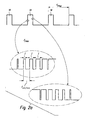
- the enlarged illustrations in FIG. 2a clarify also that the clocked switching on and off is performed with increasing or decreasing pulse length of the on signal. In this way, the switch-on or switch-off is gradually completed.
- FIG. 2b indicates so-called switch-on and switch-off, which in the Figure 2c which also shows the average drive voltage obtained from the pulse width modulation.
- the acoustically perceptible noise can be significantly reduced without the disadvantages of other solutions mentioned above occur.
Landscapes
- Engineering & Computer Science (AREA)
- Power Engineering (AREA)
- Dc-Dc Converters (AREA)
Abstract
Description
- Die Erfindung betrifft ein Verfahren zum Ansteuern eines insbesondere akkubetriebenen Elektrohandwerkzeuggeräts mittels Pulsweitenmodulation mit einer Frequenz der Pulsweitenmodulation (FPWM) von 500 - 5000 Hz.
- Des Weiteren betrifft die Erfindung eine elektronische Ansteuervorrichtung, die zur Ausführung des vorgenannten Verfahrens ausgebildet ist, und ein insbesondere akkubetriebenes Elektrohandwerkzeuggerät, das mittels Pulsweitenmodulation ansteuerbar ist.
- Beim Ansteuern von elektrischen Lasten mittels Pulsweitenmodulation (PWM-Modulation) ist mitunter infolge der Ein- und Ausschaltvorgänge ein Geräusch, etwa in Form eines Brummens oder Piepsens (je nach Frequenz der PWM-Modulation) wahrnehmbar.
- Es wurde bereits versucht, die Geräuschentwicklung durch eine analoge Ansteuerung der elektrischen Last zu umgehen. Dies ist jedoch mit sehr hohen elektrischen Verlusten verbunden. Eine andere Möglichkeit ist die Durchführung der Pulsweitenmodulation im Ultraschallfrequenzbereich; doch auch dies geht mit hohen Verlusten einher, außerdem ergeben sich Probleme im Hinblick auf die Auflösung der Pulsweitenmodulation. Wird eine Anstiegsbegrenzung durchgeführt, so ist auch dies mit sehr hohen Verlusten verbunden. Eine elektrische Glättung mittels elektrischer Energiespeicher, wie Spule und Kondensator, erfordert weitere Bauteile und eine zunehmende Baugröße.
- Der vorliegenden Erfindung liegt die Aufgabe zugrunde, der Geräuschentwicklung in anderer Weise wirksam entgegenzuwirken.
- Diese Aufgabe wird erfindungsgemäß durch ein Verfahren gelöst, das dadurch gekennzeichnet ist, dass der Einschaltvorgang und der Ausschaltvorgang bei vorzugsweise jedem einzelnen Puls seinerseits getaktet mit einer gegenüber der Frequenz der Pulsweitenmodulation (FPWm) sehr viel höheren Frequenz (Fein/aus) von 5 kHz - 50 kHz, insbesondere am oberen Ende oder außerhalb des vom menschlichen Gehör wahrnehmbaren Spektrums, durchgeführt wird, und dass der getaktet durchgeführte Einschaltvorgang wenigstens 5 Pulse umfasst, deren Länge (T) von Puls zu Puls zunimmt, und dass der getaktet durchgeführte Ausschaltvorgang wenigstens 5 Pulse umfasst, deren Länge (T) von Puls zu Puls abnimmt.
- Erfindungsgemäß wird die Last also mit einer gegenüber üblichen Frequenzen geringeren Frequenz der Pulsweitenmodulation angesteuert. Jedoch wird ein jeweiliger Pulswechsel nicht sofort und dauerhaft erzwungen, sondern der Einschaltvorgang bzw. der Ausschaltvorgang wird seinerseits mit einer Taktung höherer Frequenz, also mit einer Mehrzahl von wenigstens 5, vorzugsweise von wenigstens 6 und weiter vorzugsweise von wenigstens 7 Pulsen, durchgeführt, wobei die Frequenz dieser den Einschaltvorgang bzw. den Ausschaltvorgang bildenden Pulse außerhalb des hörbaren Spektrums liegt. Es wurde erfindungsgemäß festgestellt, dass durch diese doppelte Modulation eine Verschiebung der Umschaltgeräusche in einen höheren, bevorzugterweise nicht hörbaren Bereich erreicht werden kann, ohne dass jedoch Nachteile einer dauerhaft hochfrequenten Pulsweitenmodulation in Kauf genommen werden müssten. Auch bei einer Frequenz am oberen Ende des hörbaren Bereichs kann eine Verbesserung der Geräuschwahrnehmung erreicht werden, da der Ton hierdurch leiser wird.
- Des Weiteren erweist es sich als besonders vorteilhaft, dass der getaktet durchgeführte Einschaltvorgang mit zunehmender Pulslänge des Ein-Signals der jeweiligen Pulse durchgeführt wird. Die Frequenz bleibt dabei aber unverändert. Die PWM-Modulation beim Einschaltvorgang erfolgt also zudem noch mit ansteigender Leistung. Somit wird der Einschaltvorgang allmählich vollzogen. In entsprechender Weise wird der getaktet durchgeführte Ausschaltvorgang mit abnehmender Pulslänge des Ein-Signals der jeweiligen Pulse durchgeführt.
- Nach einer bevorzugten Ausführungsform beträgt die Frequenz der Pulsweitenmodulation (FPMM) 1000 - 3000 Hz, insbesondere 1500 - 2500 Hz und weiter insbesondere etwa 2000 Hz.
- Nach einer bevorzugten Ausführungsform beträgt die Frequenz der Taktung während des Einschaltvorgangs und Ausschaltvorgangs (Fein/aus) 10 kHz - 40 kHz und insbesondere 10 kHz - 30 kHz, und weiter insbesondere etwa 20 kHz.
- Insgesamt kann durch das erfindungsgemäße Verfahren die beim Ansteuern einer elektrischen Last mittels Pulsweitenmodulation Geräuschentwicklung erheblich reduziert werden. Die elektrischen Verluste sind im Gegensatz zu hochfrequent durchgeführten Pulsweitenmodulationen sehr viel geringer. Gegenüber einer Lösung, bei der eine "elektrische Glättung" mittels elektrischer Energiespeicher (Spule, Kondensator) durchgeführt wird, werden weniger elektrische Bauteile benötigt, und die Baugröße wird reduziert.
- Gegenstand der Erfindung ist des Weiteren eine zur Ausführung des erfindungsgemäßen Verfahrens ausgebildete elektronische Ansteuervorrichtung gemäß Anspruch 5 sowie ein Elektrohandwerkzeuggerät mit einer solchen elektronischen Ansteuervorrichtung gemäß Anspruch 6.
- Weitere Merkmale, Einzelheiten und Vorteile der Erfindung ergeben sich aus den beigefügten Patentansprüchen und der zeichnerischen Darstellung und nachfolgenden Beschreibung des erfindungsgemäßen Verfahrens. In der Zeichnung 1 zeigt:
- Figur 1
- eine schematische Darstellung eines pulsweitenmoduliert angesteuerten motorischen Antriebs eines Elektrowerkzeuggeräts;
- Figur 2a
- eine Darstellung der Pulsweitenmodulation mit vergrößerter Darstellung des Einschalt- und Ausschaltvorgangs;
- Figur 2b
- den Verlauf der durchschnittlichen an die Last angelegten Spannung mit ersichtlichen Schaltverlusten und
- Figur 2c
- zeigt, an welchen Stellen der PWM Schaltverluste entstehen, am Beispiel des getakteten Ausschaltens eines Pulses.
-
Figur 1 zeigt schematisch die Komponenten eines mittels Pulsweitenmodulation ansteuerbaren motorischen Antriebs eines Elektrowerkzeuggeräts, insbesondere akkubetriebenen Elektrohandwerkzeuggeräts. Mit Bezugszeichen 4 ist eine Energiequelle, insbesondere ein Akku, und mit Bezugszeichen 6 eine elektronische Ansteuervorrichtung zur Durchführung der Pulsweitenmodulation dargestellt. Die elektronische Ansteuervorrichtung 6 umfasst einen PWM-Controller 8 und einen Leistungsschalter 10 sowie ebenfalls schematisch dargestellt einen Bedienschalter 12 zum Einschalten bzw. Ausschalten des Elektrowerkzeuggeräts. - Erfindungsgemäß ist der PWM-Controller 8 softwaremäßig so programmiert, dass der Einschaltvorgang und der Ausschaltvorgang bei vorzugsweise jedem einzelnen Puls der Pulsweitenmodulation seinerseits getaktet durchgeführt wird. In
Figur 2a sind (nicht maßstabsgetreu) Pulse 14 dargestellt, deren Pulsfrequenz beispielsweise ca. 2000 Hz betragen kann. Die Einschaltflanke bzw. Ausschaltflanke jedes Pulses wird jedoch nicht nur einmal durchlaufen, sondern der Einschaltvorgang und der Ausschaltvorgang erfolgt getaktet mit einer gegenüber der PWM-Frequenz sehr viel höheren Frequenz, die sich außerhalb des vom menschlichen Gehör wahrnehmbaren Spektrums befindet. Diese Frequenz kann beispielsweise 20 kHz betragen. Die vergrößerten Darstellungen inFigur 2a verdeutlichen außerdem, dass der getaktet durchgeführte Einschaltvorgang und Ausschaltvorgang mit zunehmender bzw. abnehmender Pulslänge des Ein-Signals durchgeführt wird. Auf diese Weise wird der Einschaltvorgang bzw. Ausschaltvorgang allmählich vollzogen.Figur 2b deutet noch sogenannte Ein- und Ausschaltverluste an, die in derFigur 2c ebenfalls ersichtlich sind, welche die aus der Pulsweitenmodulation erhaltene durchschnittliche Ansteuerspannung wiedergibt. - Insgesamt kann bei Ausführung des erfindungsgemäßen Verfahrens die akustisch wahrnehmbare Geräuschentwicklung erheblich reduziert werden, ohne dass die eingangs erwähnten Nachteile anderer Lösungen auftreten.
Claims (6)
- Verfahren zum Ansteuern eines insbesondere akkubetriebenen Elektrohandwerkzeuggeräts mittels Pulsweitenmodulation mit einer Frequenz der Pulsweitenmodulation (FPWM) von 500 - 5000 Hz, dadurch gekennzeichnet, dass der Einschaltvorgang und der Ausschaltvorgang bei vorzugsweise jedem einzelnen Puls (14) seinerseits getaktet mit einer gegenüber der Frequenz der Pulsweitenmodulation (FPWM) sehr viel höheren Frequenz (Fein/aus) von 5 kHz - 50 kHz, insbesondere am oberen Ende oder außerhalb des vom menschlichen Gehör wahrnehmbaren Spektrums, durchgeführt wird, und dass der getaktet durchgeführte Einschaltvorgang wenigstens 5 Pulse umfasst, deren Pulslänge (T) von Puls zu Puls zunimmt, und dass der getaktet durchgeführte Ausschaltvorgang wenigstens 5 Pulse umfasst, deren Pulslänge (T) von Puls zu Puls abnimmt.
- Verfahren nach Anspruch 1, dadurch gekennzeichnet, dass der getaktet durchgeführte Einschaltvorgang und Ausschaltvorgang wenigstens 6 Pulse, insbesondere wenigstens 7 Pulse umfasst.
- Verfahren nach Anspruch 1 oder 2, dadurch gekennzeichnet, dass die Frequenz der Pulsweitenmodulation (FPWM) 1000 - 3000 Hz, insbesondere 1500 - 2500 Hz, insbesondere 2000 Hz beträgt.
- Verfahren nach Anspruch 1, 2 oder 3, dadurch gekennzeichnet, dass die Frequenz der Taktung während des Einschaltvorgangs und/oder Ausschaltvorgangs (Fein/aus) 10 kHz - 40 kHz, insbesondere 10 kHz - 30 kHz, insbesondere 20 kHz beträgt.
- Elektronische Ansteuervorrichtung zum Ansteuern eines Elektrohandwerkzeuggeräts mittels Pulsweitenmodulation, dadurch gekennzeichnet, dass die Ansteuervorrichtung (6) zur Ausführung des Verfahrens nach einem oder mehreren der vorstehenden Ansprüche ausgebildet ist.
- Elektrohandwerkzeuggerät mit einer eine Pulsweitenmodulation durchführenden elektronischen Ansteuervorrichtung nach Anspruch 5.
Priority Applications (1)
| Application Number | Priority Date | Filing Date | Title |
|---|---|---|---|
| EP09000832A EP2211456B1 (de) | 2009-01-22 | 2009-01-22 | Verfahren zum Ansteuern einer elektrischen Last, elektronische Ansteuervorrichtung zum Ausführen des Verfahrens sowie elektrische Leuchte oder Elektrohandwerkzeuggerät mit einer solchen elektronischen Ansteuervorrichtung |
Applications Claiming Priority (1)
| Application Number | Priority Date | Filing Date | Title |
|---|---|---|---|
| EP09000832A EP2211456B1 (de) | 2009-01-22 | 2009-01-22 | Verfahren zum Ansteuern einer elektrischen Last, elektronische Ansteuervorrichtung zum Ausführen des Verfahrens sowie elektrische Leuchte oder Elektrohandwerkzeuggerät mit einer solchen elektronischen Ansteuervorrichtung |
Publications (2)
| Publication Number | Publication Date |
|---|---|
| EP2211456A1 true EP2211456A1 (de) | 2010-07-28 |
| EP2211456B1 EP2211456B1 (de) | 2011-08-17 |
Family
ID=40852387
Family Applications (1)
| Application Number | Title | Priority Date | Filing Date |
|---|---|---|---|
| EP09000832A Ceased EP2211456B1 (de) | 2009-01-22 | 2009-01-22 | Verfahren zum Ansteuern einer elektrischen Last, elektronische Ansteuervorrichtung zum Ausführen des Verfahrens sowie elektrische Leuchte oder Elektrohandwerkzeuggerät mit einer solchen elektronischen Ansteuervorrichtung |
Country Status (1)
| Country | Link |
|---|---|
| EP (1) | EP2211456B1 (de) |
Cited By (2)
| Publication number | Priority date | Publication date | Assignee | Title |
|---|---|---|---|---|
| EP2966763A1 (de) * | 2014-07-07 | 2016-01-13 | Intel Corporation | Verfahren zur reduzierung von schaltgeräuschen und zur verbesserung der transienten reaktion in spannungsreglern |
| DE102012201163B4 (de) * | 2012-01-26 | 2017-02-23 | Continental Teves Ag & Co. Ohg | Stellverfahren und steuereinheit zum stellen einer ansteuerfrequenz eines komfortorientiert betreibbaren elektrischen aktuators sowie deren verwendung |
Citations (6)
| Publication number | Priority date | Publication date | Assignee | Title |
|---|---|---|---|---|
| US5001619A (en) * | 1987-12-07 | 1991-03-19 | Kabushiki Kaisha Toshiba | Harmonics suppression control circuit for a PWM inverter |
| FR2726134A1 (fr) * | 1994-10-19 | 1996-04-26 | Physic Plus Sarl | Onduleur a interrupteurs commandes permettant la visualisation et la selection des etapes de conversion |
| EP0658266B1 (de) * | 1992-09-04 | 1996-12-04 | Deutsche Thomson-Brandt Gmbh | Verfahren und vorrichtung zur ansteuerung mit gepulsten signalen |
| US6144176A (en) * | 1996-10-02 | 2000-11-07 | Lucent Technologies Inc. | Method for reducing acoustic and vibration energy radiated from rotating machines |
| US20060214609A1 (en) * | 2003-01-24 | 2006-09-28 | Peter Buerk | Method and control circuit for reducing line-bound disturbances in a pulse-width modulated control of an electric motor |
| US20080094194A1 (en) * | 2006-09-14 | 2008-04-24 | Wilfried Beneker | Adjusting mechanism of a motor vehicle, in particular for automobile seats, and method for operating such an adjusting mechanism and its use |
-
2009
- 2009-01-22 EP EP09000832A patent/EP2211456B1/de not_active Ceased
Patent Citations (6)
| Publication number | Priority date | Publication date | Assignee | Title |
|---|---|---|---|---|
| US5001619A (en) * | 1987-12-07 | 1991-03-19 | Kabushiki Kaisha Toshiba | Harmonics suppression control circuit for a PWM inverter |
| EP0658266B1 (de) * | 1992-09-04 | 1996-12-04 | Deutsche Thomson-Brandt Gmbh | Verfahren und vorrichtung zur ansteuerung mit gepulsten signalen |
| FR2726134A1 (fr) * | 1994-10-19 | 1996-04-26 | Physic Plus Sarl | Onduleur a interrupteurs commandes permettant la visualisation et la selection des etapes de conversion |
| US6144176A (en) * | 1996-10-02 | 2000-11-07 | Lucent Technologies Inc. | Method for reducing acoustic and vibration energy radiated from rotating machines |
| US20060214609A1 (en) * | 2003-01-24 | 2006-09-28 | Peter Buerk | Method and control circuit for reducing line-bound disturbances in a pulse-width modulated control of an electric motor |
| US20080094194A1 (en) * | 2006-09-14 | 2008-04-24 | Wilfried Beneker | Adjusting mechanism of a motor vehicle, in particular for automobile seats, and method for operating such an adjusting mechanism and its use |
Cited By (3)
| Publication number | Priority date | Publication date | Assignee | Title |
|---|---|---|---|---|
| DE102012201163B4 (de) * | 2012-01-26 | 2017-02-23 | Continental Teves Ag & Co. Ohg | Stellverfahren und steuereinheit zum stellen einer ansteuerfrequenz eines komfortorientiert betreibbaren elektrischen aktuators sowie deren verwendung |
| EP2966763A1 (de) * | 2014-07-07 | 2016-01-13 | Intel Corporation | Verfahren zur reduzierung von schaltgeräuschen und zur verbesserung der transienten reaktion in spannungsreglern |
| US9490701B2 (en) | 2014-07-07 | 2016-11-08 | Intel Corporation | Techniques for reducing switching noise and improving transient response in voltage regulators |
Also Published As
| Publication number | Publication date |
|---|---|
| EP2211456B1 (de) | 2011-08-17 |
Similar Documents
| Publication | Publication Date | Title |
|---|---|---|
| EP2349041B1 (de) | Hf-chirurgiegenerator | |
| EP1333707B1 (de) | Elektronisches Vorschaltgerät für Gasentladungslampe | |
| EP1935213B1 (de) | Verfahren zum betrieb einer induktionsheizeinrichtung | |
| EP3028377B1 (de) | Gleichspannungswandler | |
| EP2385745A1 (de) | Verfahren zur Vermeidung bzw. Reduktion von Störschall in einer Umrichterschaltung bei gleichzeitigem Betrieb mehrerer Ausgänge | |
| EP2850725B1 (de) | Verfahren zur regelung einer stromquelle, sowie stromquelle und prozessregler hierfür | |
| WO2009027326A1 (de) | Verfahren zur ansteuerung eines elektrischen umrichters sowie zugehörige vorrichtung | |
| EP2469970B1 (de) | Gargerätevorrichtung | |
| EP2066011B1 (de) | Verfahren zur Steuerung eines Gleichstromstellers | |
| EP2365599A1 (de) | Vorrichtung zur Wandlung elektrischer Energie und Verfahren zum Betreiben einer derartigen Vorrichtung | |
| EP2211456B1 (de) | Verfahren zum Ansteuern einer elektrischen Last, elektronische Ansteuervorrichtung zum Ausführen des Verfahrens sowie elektrische Leuchte oder Elektrohandwerkzeuggerät mit einer solchen elektronischen Ansteuervorrichtung | |
| EP2469972B1 (de) | Gargerätevorrichtung sowie Verfahren zum Steuern der Gargerätevorrichtung bei dem eine Flickerkenngrösse iterativ verkleinert wird. | |
| EP2792061B1 (de) | Wahlweise steuerung eines wechselstrommotors oder gleichstrommotors | |
| EP3672053A1 (de) | Steuerverfahren für einen dual active bridge serienresonanzwandler und nach dem verfahren arbeitender dual active bridge serienresonanzwandler | |
| EP3619804B1 (de) | Verfahren zur ansteuerung eines stromrichters, steuervorrichtung für einen stromrichter und stromrichter | |
| EP3174204B1 (de) | Verfahren und vorrichtung zum steuern eines elektrischen oder elektronischen schaltelements | |
| EP3399632A1 (de) | Ansteuerung von halbleiter-leistungsschaltern | |
| EP2548407B1 (de) | Kochmuldenvorrichtung | |
| WO2017050534A1 (de) | Verfahren und steuervorrichtung zum betrieb eines elektrischen antriebsstrangs | |
| EP1992060B1 (de) | Vorrichtung und verfahren zur gleichspannungsversorgung von elektronischen ansteuerschaltungen für elektromotoren | |
| EP4016829A1 (de) | Stromrichter und verfahren zum betrieb eines stromrichters | |
| DE102020205919A1 (de) | Steuervorrichtung und Steuerverfahren für ein elektrisches Antriebssystem und elektrisches Antriebssystem | |
| DE102022201511B4 (de) | Verfahren zur Ansteuerung von Leistungshalbleitern eines Inverters, Computerprogramm, Vorrichtung zur Datenverarbeitung, Inverter, Elektroantrieb sowie Fahrzeug | |
| DE102009007522B4 (de) | Steuerschaltung für einen Drehstromasynchronmotor | |
| EP2448104A2 (de) | System bestehend aus einer Kunststoffverarbeitungsmaschine und einem Peripheriegerät sowie Verfahren zum Betreiben eines solchen |
Legal Events
| Date | Code | Title | Description |
|---|---|---|---|
| PUAI | Public reference made under article 153(3) epc to a published international application that has entered the european phase |
Free format text: ORIGINAL CODE: 0009012 |
|
| AK | Designated contracting states |
Kind code of ref document: A1 Designated state(s): AT BE BG CH CY CZ DE DK EE ES FI FR GB GR HR HU IE IS IT LI LT LU LV MC MK MT NL NO PL PT RO SE SI SK TR |
|
| AX | Request for extension of the european patent |
Extension state: AL BA RS |
|
| 17P | Request for examination filed |
Effective date: 20100811 |
|
| GRAP | Despatch of communication of intention to grant a patent |
Free format text: ORIGINAL CODE: EPIDOSNIGR1 |
|
| RIC1 | Information provided on ipc code assigned before grant |
Ipc: H02P 7/29 20060101AFI20101018BHEP |
|
| GRAS | Grant fee paid |
Free format text: ORIGINAL CODE: EPIDOSNIGR3 |
|
| AKX | Designation fees paid |
Designated state(s): DE FR GB |
|
| GRAA | (expected) grant |
Free format text: ORIGINAL CODE: 0009210 |
|
| AK | Designated contracting states |
Kind code of ref document: B1 Designated state(s): DE FR GB |
|
| REG | Reference to a national code |
Ref country code: GB Ref legal event code: FG4D Free format text: NOT ENGLISH |
|
| REG | Reference to a national code |
Ref country code: DE Ref legal event code: R096 Ref document number: 502009001096 Country of ref document: DE Effective date: 20111020 |
|
| PLBE | No opposition filed within time limit |
Free format text: ORIGINAL CODE: 0009261 |
|
| STAA | Information on the status of an ep patent application or granted ep patent |
Free format text: STATUS: NO OPPOSITION FILED WITHIN TIME LIMIT |
|
| 26N | No opposition filed |
Effective date: 20120521 |
|
| REG | Reference to a national code |
Ref country code: DE Ref legal event code: R097 Ref document number: 502009001096 Country of ref document: DE Effective date: 20120521 |
|
| REG | Reference to a national code |
Ref country code: FR Ref legal event code: PLFP Year of fee payment: 8 |
|
| REG | Reference to a national code |
Ref country code: FR Ref legal event code: PLFP Year of fee payment: 9 |
|
| REG | Reference to a national code |
Ref country code: FR Ref legal event code: PLFP Year of fee payment: 10 |
|
| PGFP | Annual fee paid to national office [announced via postgrant information from national office to epo] |
Ref country code: DE Payment date: 20200123 Year of fee payment: 12 Ref country code: GB Payment date: 20200127 Year of fee payment: 12 |
|
| PGFP | Annual fee paid to national office [announced via postgrant information from national office to epo] |
Ref country code: FR Payment date: 20200123 Year of fee payment: 12 |
|
| REG | Reference to a national code |
Ref country code: DE Ref legal event code: R119 Ref document number: 502009001096 Country of ref document: DE |
|
| GBPC | Gb: european patent ceased through non-payment of renewal fee |
Effective date: 20210122 |
|
| PG25 | Lapsed in a contracting state [announced via postgrant information from national office to epo] |
Ref country code: FR Free format text: LAPSE BECAUSE OF NON-PAYMENT OF DUE FEES Effective date: 20210131 |
|
| PG25 | Lapsed in a contracting state [announced via postgrant information from national office to epo] |
Ref country code: DE Free format text: LAPSE BECAUSE OF NON-PAYMENT OF DUE FEES Effective date: 20210803 Ref country code: GB Free format text: LAPSE BECAUSE OF NON-PAYMENT OF DUE FEES Effective date: 20210122 |