EP2211323B1 - Method of formulating response to expired timer for data link message - Google Patents
Method of formulating response to expired timer for data link message Download PDFInfo
- Publication number
- EP2211323B1 EP2211323B1 EP10150468A EP10150468A EP2211323B1 EP 2211323 B1 EP2211323 B1 EP 2211323B1 EP 10150468 A EP10150468 A EP 10150468A EP 10150468 A EP10150468 A EP 10150468A EP 2211323 B1 EP2211323 B1 EP 2211323B1
- Authority
- EP
- European Patent Office
- Prior art keywords
- message
- data link
- timer
- response
- link message
- Prior art date
- Legal status (The legal status is an assumption and is not a legal conclusion. Google has not performed a legal analysis and makes no representation as to the accuracy of the status listed.)
- Active
Links
Images


Classifications
-
- G—PHYSICS
- G08—SIGNALLING
- G08G—TRAFFIC CONTROL SYSTEMS
- G08G5/00—Traffic control systems for aircraft
- G08G5/50—Navigation or guidance aids
- G08G5/56—Navigation or guidance aids for two or more aircraft
-
- G—PHYSICS
- G08—SIGNALLING
- G08G—TRAFFIC CONTROL SYSTEMS
- G08G5/00—Traffic control systems for aircraft
- G08G5/20—Arrangements for acquiring, generating, sharing or displaying traffic information
- G08G5/21—Arrangements for acquiring, generating, sharing or displaying traffic information located onboard the aircraft
-
- G—PHYSICS
- G08—SIGNALLING
- G08G—TRAFFIC CONTROL SYSTEMS
- G08G5/00—Traffic control systems for aircraft
- G08G5/20—Arrangements for acquiring, generating, sharing or displaying traffic information
- G08G5/26—Transmission of traffic-related information between aircraft and ground stations
-
- H—ELECTRICITY
- H04—ELECTRIC COMMUNICATION TECHNIQUE
- H04L—TRANSMISSION OF DIGITAL INFORMATION, e.g. TELEGRAPHIC COMMUNICATION
- H04L69/00—Network arrangements, protocols or services independent of the application payload and not provided for in the other groups of this subclass
- H04L69/28—Timers or timing mechanisms used in protocols
Definitions
- Air traffic control (ATC) centers are used at most airports to coordinate take-offs, landings, and general aircraft traffic around the airport. Traditionally, a pilot uses a radio to speak to an ATC center to request permission or to receive instructions from the ATC center. With increasing air traffic, it has become difficult for ATC centers and pilots to process all of the oral communications with aircraft without error. Consequently, data link applications have been developed to provide textual communications between pilots and air traffic controllers.
- CPDLC Controller Pilot Data Link Communication
- the pilot is informed of the expiration. For example, in a conventional communication management unit (CMU) the status of the message in a message log is changed to EXPIRED. In one implementation, as the status changes, the pilot is given a sidelink message indicating the downlink has expired and that the pilot should resend the request. Upon notification, the pilot will likely want to resend the clearance request and maybe modify the request. However, the pilot has to remember what the previous message stated, or print out the previous message, and then manually re-enter the entire message before resending the message. This substantially increases the aircraft crew workload and head down time, which adds to pilot fatigue and distraction while operating the aircraft. This equally applies to the air traffic controller.
- CMU communication management unit
- European Patent Application EP 2012493 teaches how the work-load of an aircraft crew and the air traffic controller can be reduced using CPDLC.
- the present invention relates to a method for communicating a data link message, including a method of formulating a response to an expired message timer for a data link message.
- the method comprises transmitting a data link message from a sender to a receiver, storing the trasmitted data link message, and starting a message timer when the data link message is transmitted.
- the method further comprises determining whether a response to the data link message has been received, and determining whether the message timer has expired if the response has not been received.
- the sender is notified when the message timer has expired and the response has not been received.
- Input is requested from the sender whether or not to retransmit the data link message. If input is received from the sender to retransmit, the data link message is displayed to the sender for review and edit. The data link message is then retransmitted from the sender to the receiver.
- the present invention is directed to a method of formulating a response to an expired message timer for a data link message, such as an expired Termination Timer, Sender (TTS) message timer for a Controller Pilot Data Link Communication (CPDLC) message.
- TTS Termination Timer
- CPDLC Controller Pilot Data Link Communication
- the present method provides the advantage of reducing aircraft crew workload and minimizing pilot head down time, as well as reducing air traffic controller workload.
- a data link message is tranmitted from a sender to a receiver, the transmitted data link message is stored, and a message timer is started. Thereafter, a determination is made whether a response to the data link message has been received, and if not, a determination is made whether the message timer has expired.
- the sender is notified when the message timer has expired with no response message received, and a determination is then made whether the sender wants to retransmit the data link message. If the the sender decides to retransmit the data link message, the orginal data link message is shown to the sender prior to retransmittal of the data link message. The sender can edit the original data link message, if desired, prior to retransmittal.
- the present method can be implemented in a communication management function (CMF) of a communication management unit (CMU); in a flight management computer (FMC) such as an FMC hosting CPDLC applications; or in any other avionics computer in an aircraft.
- CMF communication management function
- FMC flight management computer
- the present method can also be implemented as part of the CPDLC software in an air traffic control computer.
- the present method can be a part of the communication protocols for future air navigation system (FANS) CPDLC systems, or aeronautical telecommunication network (ATN) CPDLC systems.
- FANS future air navigation system
- ATN aeronautical telecommunication network
- sidelink refers to a message sent automatically from the avionics or ATC system to the user such as a pilot or air traffic controller as opposed to an uplink or downlink (but may be treated very similarly as an uplink or downlink).
- the pilot is prompted on a display screen by notification about the data link message expiration to see if the pilot would like to resend the downlink.
- the data link message can be a CPDLC ATC downlink clearance request that is monitored by a TTS timer. If the pilot indicates that he/she would like to re-send the message, then the pilot is redirected to a page on the display screen where the message can be reviewed, edited, and sent again. In this approach, the pilot does not have to go back and figure out what the old message was, re-enter the information, and then send the message again as in conventional methods.
- the present method may also be implemented in an air traffic control computer to similar effect on the air traffic controller side as well.
- TTS timer used in the present approach is described in further detail in Interoperability Requirements Standard for Aeronautical Telecommunication Network Baseline 1, RTCA, Inc., vol. 1, sec. 4.2.1, pp. 102-107 (2007 ), which is incorporated by reference herein.
- the present method can be implemented using voice readback/recognition software or supplemented with voice readback/recognition software.
- the sidelink can be replaced or supplemented with a voice readback function, and button pushes can be replaced by voice commands.
- the present method can be implemented for an aircraft by modifying conventional avionics software to add appropriate logic steps to perform the method.
- the present method can be implemented for an air traffic control system on the ground by modifying the air traffic controller workstation software to add logic steps to perform the method. It should be understood that the avionics and ground implementations of the present method utilize the same unique features but are independent of each other. Thus, the present method can function even if only one of the aircraft or the air traffic control system has been implemented with software for performing the method.
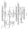
- Figure 1 is a flow diagram representing a method 100 of formulating a response to an expired TTS timer for a data link message according one approach of the present invention.
- method 100 is described with respect to messages sent from a pilot to an ATC ground station, the method can be applied in the same way to messages sent to a pilot from the ground station.
- the method 100 starts when a downlink (DL) message is sent, such as a CPDLC message sent from a pilot, and the downlink messeage is saved in a message log (block 110).
- the message log stores various uplink, downlink, and sidelink messages for later use by the pilot.
- a determination is then made whether a TTS timer is needed (block 114). If not, then the TTS timer is not started and method 100 is done (block 118). If the TTS timer is needed, then the TTS timer is started or restarted (block 120).
- a query is made whether the TTS timer has expired (block 134). If the TTS timer has not expired, then the method returns to block 124. If the TTS timer has expired at block 134, then a downlink message status is updated to indicate the TTS timer has expired (block 138). A first display page is then created that shows the downlink message and queries whether the pilot wants to resend the downlink message due to the TTS timer expiration (block 140), determination is then made whether the pilot has given a response to the query (block 144). If no response is given, the query at block 144 is repeated.
- method 100 is done and terminated (block 148). If the pilot gives a positive response to the query at block 140 and confirms, the original downlink message is recreated on a second display page for review by the pilot (block 150). The pilot can edit the message prior to resending if desired.
- Figure 2 depicts a pilot display device 200, showing an exemplary sidelink page for a data link message that is displayed on a screen 210 when the TTS timer has expired during operation of the present method, according to one implementation.
- the display device 200 has manual buttons 1L to 6L on the left side of screen 210, and manual buttons 1R to 6R on the right side of screen 210.
- the display device 200 can be implemented as part of a Human-Machine Interface (HMI) device, such as those currently used by pilots in the cock-pits of various aircraft.
- HMI Human-Machine Interface
- Examples of such HMI devices include a Multi-Control Display Unit (MCDU), and a Multi Function Display (MFD) system.
- MCDU Multi-Control Display Unit
- MFD Multi Function Display
- the display device 200 shows the data link (DLK) ATC Status Message (MSG):
- the display device 200 also shows the message that was previously sent, which in this case states:
- the pilot can respond by pushing the appropriate button corresponding to various selections, including NEGATIVE (5L), AFFIRM (5R), DLK MENU (6L), or PRINT (6R).
- NEGATIVE 5L
- AFFIRM 5R
- DLK MENU 6L
- PRINT 6R
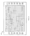
- screen 210 displays a Verify page for the data link ATC message to be resent, as depicted in Figure 3 .
- the Verify page displays the original downlink message for review by the pilot:
- the Verify page allows the pilot to select various functions, including EDIT (5L), SEND (6R), and DLK MENU (6L), by pushing the appropriate button. This allows the pilot to resend the original message again without having to re-enter the downlink message information.
- the pilot can also edit the original message at the Verify page prior to resending the message.
- FIG. 4 is a block diagram of a computer system 400 that can implement the present method.
- the computer system 400 can be implemented as a flight communications management unit, a flight management computer, or an air traffic control computer.
- the computer system 400 comprises a processing and storage platform 410, which includes at least one processor 420 and at least one memory device 424 in operative communication with processor 420.
- the computer system 400 can also incorporate a data link message module 430, such as a CPDLC application module, to enable transmission and reception of data link messages.
- the data link message module 430 is in operative communication with processor 420 and memory device 424.
- the processor 420 can be implemented using software, firmware, hardware, or any appropriate combination thereof, as known to one of skill in the art.
- hardware components for processor 420 can include one or more microprocessors, memory elements, digital signal processing (DSP) elements, interface cards, and other standard components known in the art. Any of the foregoing may be supplemented by, or incorporated in, specially-designed application-specific integrated circuits (ASICs) or field programmable gate arrays (FPGAs).
- processor 420 includes or functions with software programs, firmware, or other computer readable instructions for carrying out various process tasks, calculations, and control functions, used in the present method. These instructions are typically tangibly embodied on any appropriate medium used for storage of computer readable instructions or data structures.
- the memory device 424 can be implemented with any available computer readable storage media that can be accessed by a general purpose or special purpose computer or processor, or any programmable logic device.
- Suitable computer readable media may include storage or memory media such as magnetic or optical media.
- storage or memory media may include conventional hard disks, Compact Disk - Read Only Memory (CD-ROM), DVDs, volatile or non-volatile media such as Random Access Memory (RAM) (including, but not limited to, Synchronous Dynamic Random Access Memory (SDRAM), Double Data Rate (DDR) RAM, RAMBUS Dynamic RAM (RDRAM), Static RAM (SRAM), and the like), Read Only Memory (ROM), Electrically Erasable Programmable ROM (EEPROM), flash memory, and the like.
- RAM Random Access Memory
- SDRAM Synchronous Dynamic Random Access Memory
- DDR Double Data Rate
- RDRAM RAMBUS Dynamic RAM
- SRAM Static RAM
- EEPROM Electrically Erasable Programmable ROM
- flash memory and the like.
- the method of the invention can be implemented in computer readable instructions, such as program modules or applications, which are executed by a data processor.
- program modules or applications include routines, programs, objects, data components, data structures, algorithms, and the like, which perform particular tasks or implement particular abstract data types.
- program code means for executing steps of the methods disclosed herein.
- the particular sequence of such executable instructions or associated data structures represent examples of corresponding acts for implementing the functions described in such steps.
Landscapes
- Engineering & Computer Science (AREA)
- Aviation & Aerospace Engineering (AREA)
- Physics & Mathematics (AREA)
- General Physics & Mathematics (AREA)
- Computer Security & Cryptography (AREA)
- Computer Networks & Wireless Communication (AREA)
- Signal Processing (AREA)
- Traffic Control Systems (AREA)
- Communication Control (AREA)
- Data Exchanges In Wide-Area Networks (AREA)
- Mobile Radio Communication Systems (AREA)
Abstract
Description
- Air traffic control (ATC) centers are used at most airports to coordinate take-offs, landings, and general aircraft traffic around the airport. Traditionally, a pilot uses a radio to speak to an ATC center to request permission or to receive instructions from the ATC center. With increasing air traffic, it has become difficult for ATC centers and pilots to process all of the oral communications with aircraft without error. Consequently, data link applications have been developed to provide textual communications between pilots and air traffic controllers.
- One of these data-link applications, called Controller Pilot Data Link Communication (CPDLC), provides for the direct exchange of text-based messages between a controller and a pilot. The CPDLC application enables the pilot to communicate electronically with an ATC center by guiding the pilot through a series of screen configurations or displays that either elicit flight information from the pilot or notify the pilot regarding flight information. The CPDLC application may be part of a larger flight information/control program or may serve as a stand-alone program.
- In current CPDLC systems, when the TTS (Termination Timer, Sender) timer expires for a CPDLC clearance downlink request message, the pilot is informed of the expiration. For example, in a conventional communication management unit (CMU) the status of the message in a message log is changed to EXPIRED. In one implementation, as the status changes, the pilot is given a sidelink message indicating the downlink has expired and that the pilot should resend the request. Upon notification, the pilot will likely want to resend the clearance request and maybe modify the request. However, the pilot has to remember what the previous message stated, or print out the previous message, and then manually re-enter the entire message before resending the message. This substantially increases the aircraft crew workload and head down time, which adds to pilot fatigue and distraction while operating the aircraft. This equally applies to the air traffic controller.
- European Patent Application
EP 2012493 teaches how the work-load of an aircraft crew and the air traffic controller can be reduced using CPDLC. - The present invention relates to a method for communicating a data link message, including a method of formulating a response to an expired message timer for a data link message. The method comprises transmitting a data link message from a sender to a receiver, storing the trasmitted data link message, and starting a message timer when the data link message is transmitted. The method further comprises determining whether a response to the data link message has been received, and determining whether the message timer has expired if the response has not been received. The sender is notified when the message timer has expired and the response has not been received. Input is requested from the sender whether or not to retransmit the data link message. If input is received from the sender to retransmit, the data link message is displayed to the sender for review and edit. The data link message is then retransmitted from the sender to the receiver.
- Features of the present invention will become apparent to those skilled in the art from the following description with reference to the drawings. Understanding that the drawings depict only typical embodiments of the invention and are not therefore to be considered limiting in scope, the invention will be described with additional specificity and detail through the use of the accompanying drawings, in which:
-
Figure 1 is a flow diagram representing a method of formulating a response to an expired Termination Timer, Sender (TTS) timer for a data link message according one approach of the present invention; -
Figure 2 depicts a pilot display device showing an exemplary sidelink or communication system alert page for a data link message that is displayed when the TTS timer has expired during operation of the method of the invention; -
Figure 3 depicts the pilot display device ofFigure 2 , showing an exemplary Verify page for a data link message that is to be resent during operation of the method of the invention; and -
Figure 4 is a block diagram of a computer system that can implement the method of the invention. - In the following detailed description, embodiments are described in sufficient detail to enable those skilled in the art to practice the invention. It is to be understood that other embodiments may be utilized without departing from the scope of the present invention. The following detailed description is, therefore, not to be taken in a limiting sense.
- The present invention is directed to a method of formulating a response to an expired message timer for a data link message, such as an expired Termination Timer, Sender (TTS) message timer for a Controller Pilot Data Link Communication (CPDLC) message. The present method provides the advantage of reducing aircraft crew workload and minimizing pilot head down time, as well as reducing air traffic controller workload.
- In one approach of the present method, a data link message is tranmitted from a sender to a receiver, the transmitted data link message is stored, and a message timer is started. Thereafter, a determination is made whether a response to the data link message has been received, and if not, a determination is made whether the message timer has expired. The sender is notified when the message timer has expired with no response message received, and a determination is then made whether the sender wants to retransmit the data link message. If the the sender decides to retransmit the data link message, the orginal data link message is shown to the sender prior to retransmittal of the data link message. The sender can edit the original data link message, if desired, prior to retransmittal.
- The present method can be implemented in a communication management function (CMF) of a communication management unit (CMU); in a flight management computer (FMC) such as an FMC hosting CPDLC applications; or in any other avionics computer in an aircraft. The present method can also be implemented as part of the CPDLC software in an air traffic control computer. In addition, the present method can be a part of the communication protocols for future air navigation system (FANS) CPDLC systems, or aeronautical telecommunication network (ATN) CPDLC systems.
- Current CMF, CMU, and FMC systems supporting CPDLC (both FANS and ATN versions) have a sidelink or communication system alert type message. In implementing the present method, the existing sidelink can be enhanced to prompt a flight crew if they want to resend the expired message, or a new sidelink can be added to perform this function. The term "sidelink" as used herein refers to a message sent automatically from the avionics or ATC system to the user such as a pilot or air traffic controller as opposed to an uplink or downlink (but may be treated very similarly as an uplink or downlink).
- When the present method is implemented in an aircraft avionics computer, the pilot is prompted on a display screen by notification about the data link message expiration to see if the pilot would like to resend the downlink. For example, the data link message can be a CPDLC ATC downlink clearance request that is monitored by a TTS timer. If the pilot indicates that he/she would like to re-send the message, then the pilot is redirected to a page on the display screen where the message can be reviewed, edited, and sent again. In this approach, the pilot does not have to go back and figure out what the old message was, re-enter the information, and then send the message again as in conventional methods. The present method may also be implemented in an air traffic control computer to similar effect on the air traffic controller side as well.
- The TTS timer used in the present approach is described in further detail in Interoperability Requirements Standard for Aeronautical Telecommunication Network ), which is incorporated by reference herein.
- In another embodiment, the present method can be implemented using voice readback/recognition software or supplemented with voice readback/recognition software. For example, the sidelink can be replaced or supplemented with a voice readback function, and button pushes can be replaced by voice commands.
- The present method can be implemented for an aircraft by modifying conventional avionics software to add appropriate logic steps to perform the method. The present method can be implemented for an air traffic control system on the ground by modifying the air traffic controller workstation software to add logic steps to perform the method. It should be understood that the avionics and ground implementations of the present method utilize the same unique features but are independent of each other. Thus, the present method can function even if only one of the aircraft or the air traffic control system has been implemented with software for performing the method.
- The method of the present invention is described in further detail as follows with reference to the drawings.
-
Figure 1 is a flow diagram representing amethod 100 of formulating a response to an expired TTS timer for a data link message according one approach of the present invention. Althoughmethod 100 is described with respect to messages sent from a pilot to an ATC ground station, the method can be applied in the same way to messages sent to a pilot from the ground station. - The
method 100 starts when a downlink (DL) message is sent, such as a CPDLC message sent from a pilot, and the downlink messeage is saved in a message log (block 110). The message log stores various uplink, downlink, and sidelink messages for later use by the pilot. A determination is then made whether a TTS timer is needed (block 114). If not, then the TTS timer is not started andmethod 100 is done (block 118). If the TTS timer is needed, then the TTS timer is started or restarted (block 120). - A determination is then made whether an uplink response to the downlink message has been received (block 124). If yes, then a query is made whether the uplink response is a standby message (block 128). If the uplink response is a standby message, then the method returns to block 120 and the TTS timer is started (or restarted). If the uplink response is not a standby message, the TTS timer is stopped (block 130).
- Referring again to block 124, if an uplink response to the downlink message has not been received, then a query is made whether the TTS timer has expired (block 134). If the TTS timer has not expired, then the method returns to block 124. If the TTS timer has expired at
block 134, then a downlink message status is updated to indicate the TTS timer has expired (block 138). A first display page is then created that shows the downlink message and queries whether the pilot wants to resend the downlink message due to the TTS timer expiration (block 140),
determination is then made whether the pilot has given a response to the query (block 144). If no response is given, the query atblock 144 is repeated. If the pilot gives a negative response to the query atblock 140,method 100 is done and terminated (block 148). If the pilot gives a positive response to the query atblock 140 and confirms, the original downlink message is recreated on a second display page for review by the pilot (block 150). The pilot can edit the message prior to resending if desired. -
Figure 2 depicts apilot display device 200, showing an exemplary sidelink page for a data link message that is displayed on ascreen 210 when the TTS timer has expired during operation of the present method, according to one implementation. In one embodiment, thedisplay device 200 has manual buttons 1L to 6L on the left side ofscreen 210, andmanual buttons 1R to 6R on the right side ofscreen 210. - The
display device 200 can be implemented as part of a Human-Machine Interface (HMI) device, such as those currently used by pilots in the cock-pits of various aircraft. Examples of such HMI devices include a Multi-Control Display Unit (MCDU), and a Multi Function Display (MFD) system. - The
display device 200 shows the data link (DLK) ATC Status Message (MSG): - The
display device 200 also shows the message that was previously sent, which in this case states: - The pilot can respond by pushing the appropriate button corresponding to various selections, including NEGATIVE (5L), AFFIRM (5R), DLK MENU (6L), or PRINT (6R). When the AFFIRM button is selected,
screen 210 displays a Verify page for the data link ATC message to be resent, as depicted inFigure 3 . The Verify page displays the original downlink message for review by the pilot: - The Verify page allows the pilot to select various functions, including EDIT (5L), SEND (6R), and DLK MENU (6L), by pushing the appropriate button. This allows the pilot to resend the original message again without having to re-enter the downlink message information. The pilot can also edit the original message at the Verify page prior to resending the message.
- It should be understood that the present method can be used for a wide variety of different types of data link messages utilized during flight of an aircraft.
-
Figure 4 is a block diagram of acomputer system 400 that can implement the present method. Thecomputer system 400 can be implemented as a flight communications management unit, a flight management computer, or an air traffic control computer. Thecomputer system 400 comprises a processing andstorage platform 410, which includes at least oneprocessor 420 and at least onememory device 424 in operative communication withprocessor 420. Thecomputer system 400 can also incorporate a datalink message module 430, such as a CPDLC application module, to enable transmission and reception of data link messages. The datalink message module 430 is in operative communication withprocessor 420 andmemory device 424. - The
processor 420 can be implemented using software, firmware, hardware, or any appropriate combination thereof, as known to one of skill in the art. By way of example and not limitation, hardware components forprocessor 420 can include one or more microprocessors, memory elements, digital signal processing (DSP) elements, interface cards, and other standard components known in the art. Any of the foregoing may be supplemented by, or incorporated in, specially-designed application-specific integrated circuits (ASICs) or field programmable gate arrays (FPGAs). In this exemplary embodiment,processor 420 includes or functions with software programs, firmware, or other computer readable instructions for carrying out various process tasks, calculations, and control functions, used in the present method. These instructions are typically tangibly embodied on any appropriate medium used for storage of computer readable instructions or data structures. - The
memory device 424 can be implemented with any available computer readable storage media that can be accessed by a general purpose or special purpose computer or processor, or any programmable logic device. Suitable computer readable media may include storage or memory media such as magnetic or optical media. For example, storage or memory media may include conventional hard disks, Compact Disk - Read Only Memory (CD-ROM), DVDs, volatile or non-volatile media such as Random Access Memory (RAM) (including, but not limited to, Synchronous Dynamic Random Access Memory (SDRAM), Double Data Rate (DDR) RAM, RAMBUS Dynamic RAM (RDRAM), Static RAM (SRAM), and the like), Read Only Memory (ROM), Electrically Erasable Programmable ROM (EEPROM), flash memory, and the like. Suitable processor-readable media may also include transmission media such as electrical, electromagnetic, or digital signals, conveyed via a communication medium such as a network and/or a wireless link. Combinations of the above are also included within the scope of computer readable media. - The method of the invention can be implemented in computer readable instructions, such as program modules or applications, which are executed by a data processor. Generally, program modules or applications include routines, programs, objects, data components, data structures, algorithms, and the like, which perform particular tasks or implement particular abstract data types. These represent examples of program code means for executing steps of the methods disclosed herein. The particular sequence of such executable instructions or associated data structures represent examples of corresponding acts for implementing the functions described in such steps.
- The present invention may be embodied in other specific forms without departing from its essential characteristics. The described embodiments are to be considered in all respects only as illustrative and not restrictive. The scope of the invention is therefore indicated by the appended claims rather than by the foregoing description. All changes that come within the meaning and range of equivalency of the claims are to be embraced within their scope.
Claims (10)
- A method for communicating a data link message, the method comprising:transmitting a data link message from a sender to a receiver;storing the trasmitted data link message;starting a message timer when the data link message is transmitted;determining whether a response to the data link message has been received;determining whether the message timer has expired if the response has not been received;notifying the sender when the message timer has expired and the response has not been received;requesting input from the sender whether or not to retransmit the data link message;if input is received from the sender to retransmit the data link message, displaying the data link message to the sender for review and edit; andretransmitting the data link message from the sender to the receiver.
- The method of claim 1, wherein the sender is a pilot in an aircraft, or an air traffic controller.
- The method of claim 1, wherein the receiver is an air traffic controller, or a pilot in an aircraft.
- The method of claim 1, wherein the method is implemented as part of communication protocols for a future air navigation controller pilot data link communication (CPDLC) system.
- The method of claim 1, wherein the method is implemented as part of communication protocols for an aeronautical telecommunication network CPDLC system.
- The method of claim 1, wherein the data link message comprises a CPDLC message.
- The method of claim 1, wherein the message timer comprises a termination timer, sender (TTS) timer.
- The method of claim 1, wherein requesting input from the sender whether or not to retransmit the data link message comprises:creating a display page on a screen that shows the transmitted data link message to the sender, and asks whether the sender wants to resend the data link message.
- The method of claim 8, wherein the screen is implemented in a human-machine interface device.
- A computer system, comprising:at least one processor; andat least one memory device in operative communication with the processor, the memory device comprising a computer readable medium having program instructions stored thereon for a method of formulating a response to an expired message timer for a data link message, the method comprising:(a) storing a trasmitted data link message;(b) determining whether a message timer is needed;(c) starting the message timer when the message timer is needed;(d) determining whether a response to the data link message has been received;(e) if the response has been received, determining whether the response is a standby message;(i) if the response is a standby message, repeating the method starting at step (c); and(ii) if the response is not a standby message, stopping the message timer;(f) if the response has not been received, determining whether the message timer has expired;(g) if the message timer has not expired, repeating the method starting at step (d);(h) updating a data link message status when the message timer has expired to indicate expiration of the message timer;(i) creating a first display page that shows the data link message and queries whether to resend the data link message due to the message timer expiration; and(j) determining whether there is a response to the query on the first display page;(i) if no response to the query is received, repeating step (j);(ii) if there is a negative response to the query, terminating the method;(iii) if there is a positive response to the query, creating a second display page that shows the data link message for review and edit prior to resending the data link message.
Applications Claiming Priority (1)
| Application Number | Priority Date | Filing Date | Title |
|---|---|---|---|
| US12/358,918 US8284043B2 (en) | 2009-01-23 | 2009-01-23 | Method of formulating response to expired timer for data link message |
Publications (2)
| Publication Number | Publication Date |
|---|---|
| EP2211323A1 EP2211323A1 (en) | 2010-07-28 |
| EP2211323B1 true EP2211323B1 (en) | 2011-06-29 |
Family
ID=42138729
Family Applications (1)
| Application Number | Title | Priority Date | Filing Date |
|---|---|---|---|
| EP10150468A Active EP2211323B1 (en) | 2009-01-23 | 2010-01-11 | Method of formulating response to expired timer for data link message |
Country Status (4)
| Country | Link |
|---|---|
| US (1) | US8284043B2 (en) |
| EP (1) | EP2211323B1 (en) |
| AT (1) | ATE515012T1 (en) |
| CA (1) | CA2690206A1 (en) |
Families Citing this family (36)
| Publication number | Priority date | Publication date | Assignee | Title |
|---|---|---|---|---|
| US8571586B2 (en) * | 2007-06-19 | 2013-10-29 | Honeywell International Inc. | Method for automatic standby response to reduce pilot workload |
| US8305208B2 (en) * | 2009-05-04 | 2012-11-06 | Honeywell International Inc. | Aircraft uplink message response prompt |
| US8755952B2 (en) * | 2010-09-29 | 2014-06-17 | Honeywell International Inc. | Automatic presentation of a “when can we . . . ” message composition screen responsive to a negative response message |
| WO2014105994A2 (en) * | 2012-12-28 | 2014-07-03 | Nok Nok Labs, Inc. | Query system and method to determine authentication capabilities |
| US9015482B2 (en) | 2012-12-28 | 2015-04-21 | Nok Nok Labs, Inc. | System and method for efficiently enrolling, registering, and authenticating with multiple authentication devices |
| US9083689B2 (en) | 2012-12-28 | 2015-07-14 | Nok Nok Labs, Inc. | System and method for implementing privacy classes within an authentication framework |
| US9172687B2 (en) | 2012-12-28 | 2015-10-27 | Nok Nok Labs, Inc. | Query system and method to determine authentication capabilities |
| US9306754B2 (en) | 2012-12-28 | 2016-04-05 | Nok Nok Labs, Inc. | System and method for implementing transaction signing within an authentication framework |
| US9219732B2 (en) * | 2012-12-28 | 2015-12-22 | Nok Nok Labs, Inc. | System and method for processing random challenges within an authentication framework |
| US9887983B2 (en) | 2013-10-29 | 2018-02-06 | Nok Nok Labs, Inc. | Apparatus and method for implementing composite authenticators |
| US10706132B2 (en) | 2013-03-22 | 2020-07-07 | Nok Nok Labs, Inc. | System and method for adaptive user authentication |
| US10270748B2 (en) | 2013-03-22 | 2019-04-23 | Nok Nok Labs, Inc. | Advanced authentication techniques and applications |
| US9223413B2 (en) | 2013-04-30 | 2015-12-29 | Honeywell International Inc. | Next action page key for system generated messages |
| US9961077B2 (en) | 2013-05-30 | 2018-05-01 | Nok Nok Labs, Inc. | System and method for biometric authentication with device attestation |
| US9293050B2 (en) | 2013-12-06 | 2016-03-22 | Honeywell International Inc. | System and method for tactical viewing of datalink messages |
| US9577999B1 (en) | 2014-05-02 | 2017-02-21 | Nok Nok Labs, Inc. | Enhanced security for registration of authentication devices |
| US9654469B1 (en) | 2014-05-02 | 2017-05-16 | Nok Nok Labs, Inc. | Web-based user authentication techniques and applications |
| US10148630B2 (en) | 2014-07-31 | 2018-12-04 | Nok Nok Labs, Inc. | System and method for implementing a hosted authentication service |
| US9875347B2 (en) | 2014-07-31 | 2018-01-23 | Nok Nok Labs, Inc. | System and method for performing authentication using data analytics |
| US9749131B2 (en) | 2014-07-31 | 2017-08-29 | Nok Nok Labs, Inc. | System and method for implementing a one-time-password using asymmetric cryptography |
| US9736154B2 (en) | 2014-09-16 | 2017-08-15 | Nok Nok Labs, Inc. | System and method for integrating an authentication service within a network architecture |
| US9998360B2 (en) | 2014-11-17 | 2018-06-12 | Honeywell International Inc. | Minimizining message propagation times when brief datalink interruptions occur |
| US9660719B2 (en) * | 2014-11-17 | 2017-05-23 | Honeywell International Inc. | Minimizing propagation times of queued-up datalink TPDUs |
| US10637853B2 (en) | 2016-08-05 | 2020-04-28 | Nok Nok Labs, Inc. | Authentication techniques including speech and/or lip movement analysis |
| US10769635B2 (en) | 2016-08-05 | 2020-09-08 | Nok Nok Labs, Inc. | Authentication techniques including speech and/or lip movement analysis |
| US10237070B2 (en) | 2016-12-31 | 2019-03-19 | Nok Nok Labs, Inc. | System and method for sharing keys across authenticators |
| US10091195B2 (en) | 2016-12-31 | 2018-10-02 | Nok Nok Labs, Inc. | System and method for bootstrapping a user binding |
| US10771558B2 (en) * | 2017-04-10 | 2020-09-08 | Honeywell International Inc. | System and method for modifying multiple request datalink messages in avionics system |
| US10791120B2 (en) * | 2017-08-30 | 2020-09-29 | Lenovo Enterprise Solutions (Singapore) Pte. Ltd. | System and method for providing access to secured data via a push notification |
| US11868995B2 (en) | 2017-11-27 | 2024-01-09 | Nok Nok Labs, Inc. | Extending a secure key storage for transaction confirmation and cryptocurrency |
| US11831409B2 (en) | 2018-01-12 | 2023-11-28 | Nok Nok Labs, Inc. | System and method for binding verifiable claims |
| US12041039B2 (en) | 2019-02-28 | 2024-07-16 | Nok Nok Labs, Inc. | System and method for endorsing a new authenticator |
| US11792024B2 (en) | 2019-03-29 | 2023-10-17 | Nok Nok Labs, Inc. | System and method for efficient challenge-response authentication |
| US11742932B2 (en) | 2020-11-25 | 2023-08-29 | Honeywell International Inc. | Systems and methods for changing VHF data radio mode due to electromagnetic interference |
| US12126613B2 (en) | 2021-09-17 | 2024-10-22 | Nok Nok Labs, Inc. | System and method for pre-registration of FIDO authenticators |
| US12259897B2 (en) | 2022-05-02 | 2025-03-25 | Honeywell International Inc. | Communication system with consolidated user interface for datalink messages |
Family Cites Families (18)
| Publication number | Priority date | Publication date | Assignee | Title |
|---|---|---|---|---|
| US5003619A (en) | 1989-01-31 | 1991-03-26 | Motorola, Inc. | Method and apparatus for adjusting the power of a transmitter |
| US6195609B1 (en) | 1993-09-07 | 2001-02-27 | Harold Robert Pilley | Method and system for the control and management of an airport |
| US5434565A (en) | 1994-03-22 | 1995-07-18 | Potomac Aviation Technology Corporation | Automatic weather monitoring and adaptive transmitting system |
| US6084510A (en) * | 1997-04-18 | 2000-07-04 | Lemelson; Jerome H. | Danger warning and emergency response system and method |
| JP3406478B2 (en) | 1997-06-06 | 2003-05-12 | 沖電気工業株式会社 | Aircraft position display device for terminal control console |
| US6282417B1 (en) | 1998-05-08 | 2001-08-28 | David K. Ward | Communication radio method and apparatus |
| US6175314B1 (en) | 1999-02-25 | 2001-01-16 | Rockwell Collins, Inc. | Voice annunciation of data link ATC messages |
| US6313759B1 (en) | 2000-03-16 | 2001-11-06 | Rockwell Collins | System and method of communication between an aircraft and a ground control station |
| US20030006910A1 (en) | 2001-07-06 | 2003-01-09 | Dame Stephen G. | Aural/visual interactive aircraft communications module, system and methods |
| US7277671B2 (en) | 2002-02-14 | 2007-10-02 | Fleetwood Group, Inc. | Wireless response system and method |
| KR100498932B1 (en) | 2002-12-30 | 2005-07-04 | 삼성전자주식회사 | Apparatus and method for session establishment in radio network organized mobile nodes |
| FR2882439B1 (en) | 2005-02-18 | 2007-04-20 | Thales Sa | ONBOARD DEVICE FOR MANAGING DATA EXCHANGED BY AN AIRCRAFT WITH THE SOIL OR OTHER AIRCRAFT |
| US7495602B2 (en) | 2005-12-02 | 2009-02-24 | The Boeing Company | Single air traffic control (ATC) operator interface |
| US7848877B2 (en) | 2006-11-14 | 2010-12-07 | The Boeing Company | Displaying and/or programming airplane systems based on clearances and/or instructions |
| FR2910124B1 (en) | 2006-12-15 | 2009-03-06 | Thales Sa | METHOD FOR CREATING AND UPDATING A REAL-TIME ATC FLIGHT PLAN FOR THE TAKING INTO ACCOUNT OF FLIGHT INSTRUCTIONS AND DEVICE FOR IMPLEMENTING THE SAME |
| US8571586B2 (en) | 2007-06-19 | 2013-10-29 | Honeywell International Inc. | Method for automatic standby response to reduce pilot workload |
| US20080316057A1 (en) | 2007-06-19 | 2008-12-25 | Honeywell International Inc. | Method for automated standby message response to reduce pilot and air traffic controller workload |
| US8305208B2 (en) | 2009-05-04 | 2012-11-06 | Honeywell International Inc. | Aircraft uplink message response prompt |
-
2009
- 2009-01-23 US US12/358,918 patent/US8284043B2/en active Active
-
2010
- 2010-01-11 EP EP10150468A patent/EP2211323B1/en active Active
- 2010-01-11 AT AT10150468T patent/ATE515012T1/en not_active IP Right Cessation
- 2010-01-13 CA CA2690206A patent/CA2690206A1/en not_active Abandoned
Also Published As
| Publication number | Publication date |
|---|---|
| CA2690206A1 (en) | 2010-07-23 |
| EP2211323A1 (en) | 2010-07-28 |
| ATE515012T1 (en) | 2011-07-15 |
| US20100188266A1 (en) | 2010-07-29 |
| US8284043B2 (en) | 2012-10-09 |
Similar Documents
| Publication | Publication Date | Title |
|---|---|---|
| US8284043B2 (en) | Method of formulating response to expired timer for data link message | |
| US7580377B2 (en) | Systems and method of datalink auditory communications for air traffic control | |
| US8200213B2 (en) | Method for maintaining datalink network throughput by delaying lower priority messages | |
| US8755952B2 (en) | Automatic presentation of a “when can we . . . ” message composition screen responsive to a negative response message | |
| US8305208B2 (en) | Aircraft uplink message response prompt | |
| EP2012493B1 (en) | Method for automated standby message response to reduce pilot and air traffic controller workload | |
| EP2383714B1 (en) | Enhanced flight crew display for supporting multiple controller/pilot data link communications (CPDLC) versions | |
| US10798033B2 (en) | Processing messages for an application running on a computer external to a communications management unit (CMU) | |
| EP2902989A1 (en) | System and method to view, verify, and send datalink downlink messaging | |
| US9223413B2 (en) | Next action page key for system generated messages | |
| US20110137998A1 (en) | System and method for delivery of non-textual controller pilot data link communications (cpdlc) for pilot review | |
| US10102754B2 (en) | Systems and methods for managing controller pilot data link communication (CPDLC) systems | |
| EP2346225B1 (en) | Method and system for automatic standby response to reduce pilot workload | |
| CN112802368A (en) | Method and system for synchronizing a flight management system with an external device | |
| US20050181787A1 (en) | Systems and methods for encoding and decoding data messages | |
| US10771558B2 (en) | System and method for modifying multiple request datalink messages in avionics system | |
| US10795552B2 (en) | Avionics device and method for sending a data message to at least one receiving electronic device, receiving electronic device, associated receiving method and computer program | |
| US11743226B2 (en) | Communication system processing external clearance message functions | |
| US10971019B2 (en) | Vehicle communication and navigation system |
Legal Events
| Date | Code | Title | Description |
|---|---|---|---|
| PUAI | Public reference made under article 153(3) epc to a published international application that has entered the european phase |
Free format text: ORIGINAL CODE: 0009012 |
|
| 17P | Request for examination filed |
Effective date: 20100111 |
|
| AK | Designated contracting states |
Kind code of ref document: A1 Designated state(s): AT BE BG CH CY CZ DE DK EE ES FI FR GB GR HR HU IE IS IT LI LT LU LV MC MK MT NL NO PL PT RO SE SI SK SM TR |
|
| AX | Request for extension of the european patent |
Extension state: AL BA RS |
|
| RIC1 | Information provided on ipc code assigned before grant |
Ipc: H04L 29/06 20060101ALI20110103BHEP Ipc: G08G 5/00 20060101AFI20110103BHEP |
|
| GRAP | Despatch of communication of intention to grant a patent |
Free format text: ORIGINAL CODE: EPIDOSNIGR1 |
|
| GRAS | Grant fee paid |
Free format text: ORIGINAL CODE: EPIDOSNIGR3 |
|
| GRAA | (expected) grant |
Free format text: ORIGINAL CODE: 0009210 |
|
| AK | Designated contracting states |
Kind code of ref document: B1 Designated state(s): AT BE BG CH CY CZ DE DK EE ES FI FR GB GR HR HU IE IS IT LI LT LU LV MC MK MT NL NO PL PT RO SE SI SK SM TR |
|
| REG | Reference to a national code |
Ref country code: GB Ref legal event code: FG4D |
|
| REG | Reference to a national code |
Ref country code: CH Ref legal event code: EP |
|
| REG | Reference to a national code |
Ref country code: IE Ref legal event code: FG4D |
|
| REG | Reference to a national code |
Ref country code: DE Ref legal event code: R096 Ref document number: 602010000090 Country of ref document: DE Effective date: 20110818 |
|
| REG | Reference to a national code |
Ref country code: NL Ref legal event code: VDEP Effective date: 20110629 |
|
| PG25 | Lapsed in a contracting state [announced via postgrant information from national office to epo] |
Ref country code: NO Free format text: LAPSE BECAUSE OF FAILURE TO SUBMIT A TRANSLATION OF THE DESCRIPTION OR TO PAY THE FEE WITHIN THE PRESCRIBED TIME-LIMIT Effective date: 20110929 Ref country code: LT Free format text: LAPSE BECAUSE OF FAILURE TO SUBMIT A TRANSLATION OF THE DESCRIPTION OR TO PAY THE FEE WITHIN THE PRESCRIBED TIME-LIMIT Effective date: 20110629 Ref country code: HR Free format text: LAPSE BECAUSE OF FAILURE TO SUBMIT A TRANSLATION OF THE DESCRIPTION OR TO PAY THE FEE WITHIN THE PRESCRIBED TIME-LIMIT Effective date: 20110629 Ref country code: SE Free format text: LAPSE BECAUSE OF FAILURE TO SUBMIT A TRANSLATION OF THE DESCRIPTION OR TO PAY THE FEE WITHIN THE PRESCRIBED TIME-LIMIT Effective date: 20110629 |
|
| PG25 | Lapsed in a contracting state [announced via postgrant information from national office to epo] |
Ref country code: FI Free format text: LAPSE BECAUSE OF FAILURE TO SUBMIT A TRANSLATION OF THE DESCRIPTION OR TO PAY THE FEE WITHIN THE PRESCRIBED TIME-LIMIT Effective date: 20110629 Ref country code: AT Free format text: LAPSE BECAUSE OF FAILURE TO SUBMIT A TRANSLATION OF THE DESCRIPTION OR TO PAY THE FEE WITHIN THE PRESCRIBED TIME-LIMIT Effective date: 20110629 Ref country code: SI Free format text: LAPSE BECAUSE OF FAILURE TO SUBMIT A TRANSLATION OF THE DESCRIPTION OR TO PAY THE FEE WITHIN THE PRESCRIBED TIME-LIMIT Effective date: 20110629 Ref country code: LV Free format text: LAPSE BECAUSE OF FAILURE TO SUBMIT A TRANSLATION OF THE DESCRIPTION OR TO PAY THE FEE WITHIN THE PRESCRIBED TIME-LIMIT Effective date: 20110629 Ref country code: GR Free format text: LAPSE BECAUSE OF FAILURE TO SUBMIT A TRANSLATION OF THE DESCRIPTION OR TO PAY THE FEE WITHIN THE PRESCRIBED TIME-LIMIT Effective date: 20110930 |
|
| PG25 | Lapsed in a contracting state [announced via postgrant information from national office to epo] |
Ref country code: BE Free format text: LAPSE BECAUSE OF FAILURE TO SUBMIT A TRANSLATION OF THE DESCRIPTION OR TO PAY THE FEE WITHIN THE PRESCRIBED TIME-LIMIT Effective date: 20110629 |
|
| PG25 | Lapsed in a contracting state [announced via postgrant information from national office to epo] |
Ref country code: PT Free format text: LAPSE BECAUSE OF FAILURE TO SUBMIT A TRANSLATION OF THE DESCRIPTION OR TO PAY THE FEE WITHIN THE PRESCRIBED TIME-LIMIT Effective date: 20111031 Ref country code: IS Free format text: LAPSE BECAUSE OF FAILURE TO SUBMIT A TRANSLATION OF THE DESCRIPTION OR TO PAY THE FEE WITHIN THE PRESCRIBED TIME-LIMIT Effective date: 20111029 Ref country code: NL Free format text: LAPSE BECAUSE OF FAILURE TO SUBMIT A TRANSLATION OF THE DESCRIPTION OR TO PAY THE FEE WITHIN THE PRESCRIBED TIME-LIMIT Effective date: 20110629 Ref country code: CZ Free format text: LAPSE BECAUSE OF FAILURE TO SUBMIT A TRANSLATION OF THE DESCRIPTION OR TO PAY THE FEE WITHIN THE PRESCRIBED TIME-LIMIT Effective date: 20110629 Ref country code: EE Free format text: LAPSE BECAUSE OF FAILURE TO SUBMIT A TRANSLATION OF THE DESCRIPTION OR TO PAY THE FEE WITHIN THE PRESCRIBED TIME-LIMIT Effective date: 20110629 |
|
| PG25 | Lapsed in a contracting state [announced via postgrant information from national office to epo] |
Ref country code: PL Free format text: LAPSE BECAUSE OF FAILURE TO SUBMIT A TRANSLATION OF THE DESCRIPTION OR TO PAY THE FEE WITHIN THE PRESCRIBED TIME-LIMIT Effective date: 20110629 Ref country code: CY Free format text: LAPSE BECAUSE OF FAILURE TO SUBMIT A TRANSLATION OF THE DESCRIPTION OR TO PAY THE FEE WITHIN THE PRESCRIBED TIME-LIMIT Effective date: 20110629 Ref country code: SK Free format text: LAPSE BECAUSE OF FAILURE TO SUBMIT A TRANSLATION OF THE DESCRIPTION OR TO PAY THE FEE WITHIN THE PRESCRIBED TIME-LIMIT Effective date: 20110629 |
|
| PLBE | No opposition filed within time limit |
Free format text: ORIGINAL CODE: 0009261 |
|
| STAA | Information on the status of an ep patent application or granted ep patent |
Free format text: STATUS: NO OPPOSITION FILED WITHIN TIME LIMIT |
|
| PG25 | Lapsed in a contracting state [announced via postgrant information from national office to epo] |
Ref country code: IT Free format text: LAPSE BECAUSE OF FAILURE TO SUBMIT A TRANSLATION OF THE DESCRIPTION OR TO PAY THE FEE WITHIN THE PRESCRIBED TIME-LIMIT Effective date: 20110629 |
|
| 26N | No opposition filed |
Effective date: 20120330 |
|
| PG25 | Lapsed in a contracting state [announced via postgrant information from national office to epo] |
Ref country code: DK Free format text: LAPSE BECAUSE OF FAILURE TO SUBMIT A TRANSLATION OF THE DESCRIPTION OR TO PAY THE FEE WITHIN THE PRESCRIBED TIME-LIMIT Effective date: 20110629 |
|
| REG | Reference to a national code |
Ref country code: DE Ref legal event code: R097 Ref document number: 602010000090 Country of ref document: DE Effective date: 20120330 |
|
| PG25 | Lapsed in a contracting state [announced via postgrant information from national office to epo] |
Ref country code: MC Free format text: LAPSE BECAUSE OF NON-PAYMENT OF DUE FEES Effective date: 20120131 |
|
| REG | Reference to a national code |
Ref country code: IE Ref legal event code: MM4A |
|
| PG25 | Lapsed in a contracting state [announced via postgrant information from national office to epo] |
Ref country code: IE Free format text: LAPSE BECAUSE OF NON-PAYMENT OF DUE FEES Effective date: 20120111 |
|
| PG25 | Lapsed in a contracting state [announced via postgrant information from national office to epo] |
Ref country code: MK Free format text: LAPSE BECAUSE OF FAILURE TO SUBMIT A TRANSLATION OF THE DESCRIPTION OR TO PAY THE FEE WITHIN THE PRESCRIBED TIME-LIMIT Effective date: 20110629 |
|
| PG25 | Lapsed in a contracting state [announced via postgrant information from national office to epo] |
Ref country code: ES Free format text: LAPSE BECAUSE OF FAILURE TO SUBMIT A TRANSLATION OF THE DESCRIPTION OR TO PAY THE FEE WITHIN THE PRESCRIBED TIME-LIMIT Effective date: 20111010 |
|
| PG25 | Lapsed in a contracting state [announced via postgrant information from national office to epo] |
Ref country code: BG Free format text: LAPSE BECAUSE OF FAILURE TO SUBMIT A TRANSLATION OF THE DESCRIPTION OR TO PAY THE FEE WITHIN THE PRESCRIBED TIME-LIMIT Effective date: 20110929 |
|
| PG25 | Lapsed in a contracting state [announced via postgrant information from national office to epo] |
Ref country code: MT Free format text: LAPSE BECAUSE OF FAILURE TO SUBMIT A TRANSLATION OF THE DESCRIPTION OR TO PAY THE FEE WITHIN THE PRESCRIBED TIME-LIMIT Effective date: 20110629 |
|
| PG25 | Lapsed in a contracting state [announced via postgrant information from national office to epo] |
Ref country code: TR Free format text: LAPSE BECAUSE OF FAILURE TO SUBMIT A TRANSLATION OF THE DESCRIPTION OR TO PAY THE FEE WITHIN THE PRESCRIBED TIME-LIMIT Effective date: 20110629 |
|
| PG25 | Lapsed in a contracting state [announced via postgrant information from national office to epo] |
Ref country code: LU Free format text: LAPSE BECAUSE OF NON-PAYMENT OF DUE FEES Effective date: 20120111 Ref country code: SM Free format text: LAPSE BECAUSE OF FAILURE TO SUBMIT A TRANSLATION OF THE DESCRIPTION OR TO PAY THE FEE WITHIN THE PRESCRIBED TIME-LIMIT Effective date: 20110629 |
|
| PG25 | Lapsed in a contracting state [announced via postgrant information from national office to epo] |
Ref country code: HU Free format text: LAPSE BECAUSE OF FAILURE TO SUBMIT A TRANSLATION OF THE DESCRIPTION OR TO PAY THE FEE WITHIN THE PRESCRIBED TIME-LIMIT Effective date: 20100111 |
|
| REG | Reference to a national code |
Ref country code: CH Ref legal event code: PL |
|
| PG25 | Lapsed in a contracting state [announced via postgrant information from national office to epo] |
Ref country code: LI Free format text: LAPSE BECAUSE OF NON-PAYMENT OF DUE FEES Effective date: 20140131 Ref country code: CH Free format text: LAPSE BECAUSE OF NON-PAYMENT OF DUE FEES Effective date: 20140131 |
|
| PGFP | Annual fee paid to national office [announced via postgrant information from national office to epo] |
Ref country code: GB Payment date: 20141230 Year of fee payment: 6 |
|
| REG | Reference to a national code |
Ref country code: FR Ref legal event code: PLFP Year of fee payment: 7 |
|
| GBPC | Gb: european patent ceased through non-payment of renewal fee |
Effective date: 20160111 |
|
| PG25 | Lapsed in a contracting state [announced via postgrant information from national office to epo] |
Ref country code: GB Free format text: LAPSE BECAUSE OF NON-PAYMENT OF DUE FEES Effective date: 20160111 |
|
| REG | Reference to a national code |
Ref country code: FR Ref legal event code: PLFP Year of fee payment: 8 |
|
| REG | Reference to a national code |
Ref country code: FR Ref legal event code: PLFP Year of fee payment: 9 |
|
| PGFP | Annual fee paid to national office [announced via postgrant information from national office to epo] |
Ref country code: DE Payment date: 20220127 Year of fee payment: 13 |
|
| P01 | Opt-out of the competence of the unified patent court (upc) registered |
Effective date: 20230525 |
|
| REG | Reference to a national code |
Ref country code: DE Ref legal event code: R119 Ref document number: 602010000090 Country of ref document: DE |
|
| PG25 | Lapsed in a contracting state [announced via postgrant information from national office to epo] |
Ref country code: DE Free format text: LAPSE BECAUSE OF NON-PAYMENT OF DUE FEES Effective date: 20230801 |
|
| PGFP | Annual fee paid to national office [announced via postgrant information from national office to epo] |
Ref country code: FR Payment date: 20260127 Year of fee payment: 17 |