EP2211246A1 - System for haptics-enabled teleoperation of vehicles - Google Patents
System for haptics-enabled teleoperation of vehicles Download PDFInfo
- Publication number
- EP2211246A1 EP2211246A1 EP10162866A EP10162866A EP2211246A1 EP 2211246 A1 EP2211246 A1 EP 2211246A1 EP 10162866 A EP10162866 A EP 10162866A EP 10162866 A EP10162866 A EP 10162866A EP 2211246 A1 EP2211246 A1 EP 2211246A1
- Authority
- EP
- European Patent Office
- Prior art keywords
- control
- vehicle
- haptic
- teleoperable
- haptics
- Prior art date
- Legal status (The legal status is an assumption and is not a legal conclusion. Google has not performed a legal analysis and makes no representation as to the accuracy of the status listed.)
- Granted
Links
Images

Classifications
-
- G—PHYSICS
- G05—CONTROLLING; REGULATING
- G05D—SYSTEMS FOR CONTROLLING OR REGULATING NON-ELECTRIC VARIABLES
- G05D1/00—Control of position, course, altitude or attitude of land, water, air or space vehicles, e.g. using automatic pilots
- G05D1/0011—Control of position, course, altitude or attitude of land, water, air or space vehicles, e.g. using automatic pilots associated with a remote control arrangement
- G05D1/0033—Control of position, course, altitude or attitude of land, water, air or space vehicles, e.g. using automatic pilots associated with a remote control arrangement by having the operator tracking the vehicle either by direct line of sight or via one or more cameras located remotely from the vehicle
-
- G—PHYSICS
- G05—CONTROLLING; REGULATING
- G05D—SYSTEMS FOR CONTROLLING OR REGULATING NON-ELECTRIC VARIABLES
- G05D1/00—Control of position, course, altitude or attitude of land, water, air or space vehicles, e.g. using automatic pilots
- G05D1/0011—Control of position, course, altitude or attitude of land, water, air or space vehicles, e.g. using automatic pilots associated with a remote control arrangement
- G05D1/0027—Control of position, course, altitude or attitude of land, water, air or space vehicles, e.g. using automatic pilots associated with a remote control arrangement involving a plurality of vehicles, e.g. fleet or convoy travelling
-
- G—PHYSICS
- G05—CONTROLLING; REGULATING
- G05D—SYSTEMS FOR CONTROLLING OR REGULATING NON-ELECTRIC VARIABLES
- G05D1/00—Control of position, course, altitude or attitude of land, water, air or space vehicles, e.g. using automatic pilots
- G05D1/0011—Control of position, course, altitude or attitude of land, water, air or space vehicles, e.g. using automatic pilots associated with a remote control arrangement
- G05D1/005—Control of position, course, altitude or attitude of land, water, air or space vehicles, e.g. using automatic pilots associated with a remote control arrangement by providing the operator with signals other than visual, e.g. acoustic, haptic
Definitions
- a variety of different devices can be operated remotely, including remotely-controlled air, water, and land-based vehicles, manufacturing robots, and other suitable devices.
- such teleoperable devices require a control system that enables a human operator or a machine controller to monitor movements of the vehicle and issue appropriate control signals to cause the device to move as desired.
- a wide variety of controllable devices need control systems to effectuate the desired controllable movement.
- prior art teleoperation systems and methods may not provide the desired controllability of such devices.
- the present invention is directed to systems and methods for haptics-enabled teleoperation of devices, including remotely-controlled air, water, and land-based vehicles, manufacturing robots, and other suitable teleoperable devices.
- Embodiments of the invention may advantageously provide improved control of teleoperable devices in comparison with prior art systems and methods. For example, in some prior circumstances, the ability of an operator to control a teleoperable device may be diminished because the operator does not physically experience a feedback of forces and accelerations that the operator would experience if she were positioned onboard the teleoperable device. In the case of an aircraft, an experienced onboard pilot can often perform a landing without using instrumentation by relying on visual input and by feeling feedback ( e . g . forces and accelerations) produced by the motions of the aircraft. Physically sensing acceleration forces may be particularly important to a helicopter pilot.
- a system for teleoperation of a vehicle comprises a control component configured to provide position and orientation control with haptic force feedback of the vehicle based on a position measurement of the vehicle and configured to function in a closed-loop feedback manner.
- the position measurement may include six degree-of-freedom position data provided by a motion capture system to the control and/or haptic I/O components of the application.
- the system may also use differences in position and/or velocity between the vehicle and a haptic I/O device for feedback control.
- a method of operating a teleoperable device by directly controlling least one of position and orientation of the teleoperable device includes providing an input to a haptics device virtually coupled to the teleoperable device; providing at least one control signal to the teleoperable device based on the input, the at least one control signal being configured to directly control at least one of position and orientation of the teleoperable device; measuring at least one state characteristic of the teleoperable device; and providing a haptics output to an operator based on at least one of a response from the teleoperable device and the at least one state characteristic.
- a system for operating a teleoperable device by controlling at least one of position and orientation of the teleoperable device includes a haptics device coupleable to the teleoperable device and configured to receive an operator input; and a sensing system operatively coupled to the haptics device and configured to measure at least one state characteristic of the teleoperable device, wherein the haptics device is further configured to provide at least one control signal to the teleoperable device, the at least one control signal being configured to directly control at least one of position and orientation of the teleoperable device based on at least one of the operator input and the at least one state characteristic.
- the present invention relates to systems and methods for haptics-enabled teleoperation of devices, including such controllable devices as flight vehicles, water and land-based vehicles, manufacturing vehicles and systems, and any other suitable controllable device or system.
- controllable devices including such controllable devices as flight vehicles, water and land-based vehicles, manufacturing vehicles and systems, and any other suitable controllable device or system.
- embodiments of the present invention provide feedback of a teleoperable device's motion to an operator via a haptics-enabled feedback system.
- the operator receives feedback from the teleoperable device which may enable the operator to control the device (e . g . aircraft) using both visual and physical stimuli, thereby providing improved controllability in comparison with prior art systems.
- embodiments of methods and systems in accordance with the present invention may be implemented in either fly-by-wire control systems or direct control systems as desired.
- the teleoperation control capabilities provided by embodiments of the invention may be further extended by adding a haptic force feedback interface and a real-time simulation environment to the application. These aspects may provide an intuitive and efficient method for precise control of remotely piloted systems.
- the low level feedback of the device's motions is available to the operator, which may provide an intuitive understanding or "feel" of the dynamics of the teleoperable device.
- a basic concept of haptics-enabled embodiments described herein involves connecting force feedback calculations to a control loop through virtual coupling and proxy objects, which may be defined in a real-time simulation environment running simultaneously with a control system. This type of force feedback enables applications that require precise motion control.
- the intuitive feedback provides a more natural interface that results in more efficient operation of the vehicle or device, and also gives the remote pilot or operator a faster reaction time to unexpected disturbances.
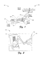
- FIG. 1 is a schematic view of a teleoperated system 100 having a teleoperable device 110 in accordance with an embodiment of the invention.
- the teleoperable device 110 is a helicopter, however, in alternate embodiments, the teleoperable device 110 may be any type of vehicle, robot, machine, or other suitable device.
- the teleoperable device 110 is a modified version of an E-flite Blade CX 180 RC helicopter commercially available from Horizon Hobby, Inc. of Champaign, Illinois.
- Control and force feedback of the teleoperable device 110 is provided by a haptics device (or handle) 120.
- a first virtual coupling 130 operatively couples the haptics device 120 to a proxy object 112, and a second virtual coupling 136 operatively couples the proxy object 112 to the teleoperable device 110.
- each of the first and second virtual couplings 130, 136 includes a multi-degree-of-freedom spring element 131, 137 and a multi-degree-of-freedom damper element 133, 138.
- FIG 2 is a perspective view image of an embodiment of the haptics device 120 of Figure 1 .
- haptics devices are interfaces for the sense of touch.
- this interface may be bi-directional, meaning that a user 124 provides position or force input to the system 100 and software controlling the haptics device 120 provides a position response by moving components (e . g . motors, actuators, etc.) in the haptics device 120. Resistance to this motion by the user 124 produces the force feedback. With haptic interaction, the user 124 may be afforded more than just another type of input device.
- Haptics devices provide a high-bandwidth channel for additional information flow to the user from the system or application.
- This type feedback of information is not available from input-only devices like joysticks.
- the interaction with the haptics device 120 is similar to what would be felt by the user if the actual vehicle was being held and manipulated by the user 124.
- the forces can be scaled so that larger or smaller vehicles can be controlled by the same type of haptic interface.
- the forces felt by the user in this type of teleoperation are computed based on a combination of the inertia forces generated by vehicle accelerations, and by constraint forces generated in the physics-based virtual environment.
- the advantage of this type of feedback is that it allows the user to perceive additional information about the vehicle's condition or the environment in which it is operating.
- the haptics device 120 is a bi-directional force feedback device in the form of an articulated robot arm, called a PHANTOM ® haptics device, which is commercially-available from SensAble Technologies, Inc. of Woburn, Massachusetts. Of course, in alternate embodiments, any other suitable embodiments of haptics devices may be used.
- the haptic device 120 includes a handle 122 having up to six inputs: three Cartesian translations (x, y, z) and three rotations (roll, pitch, yaw).
- the haptic device 120 may output forces in three Cartesian dimensions. In applications where a six degree-of-freedom output haptic device is used, additional rotation forces (torques) may also be felt through the handle 122, giving the user 124 roll, pitch, and yaw torque feedback.
- the user 124 operates the teleoperated system 100 by moving ( i.e., translating and rotating) the handle 122 of the haptics device 120, while watching either a simulation on a screen or live motion of the teleoperable device 110.
- Moving the teleoperable device 110 from one place to another involves a scaled mapping of the motion of the haptics device 120 to the motion of the teleoperable device 110.
- position control of the handle 122 of the haptics device 120 can be indexed (repositioned) by pressing a stylus button (not shown) on the handle 122.
- the indexing is similar in concept to picking up and repositioning a mouse to get a more useful position on a mouse pad. Indexing can also be applied to relative orientation.
- Movement of the haptics device 120 produces a corresponding movement of the proxy object 112 through the first virtual coupling 130, which in turn produces a movement of the teleoperable device 110 through the second virtual coupling 136.
- the details of implementing the first and second virtual couplings 130, 136 are generally known, and will be described in greater detail below.
- the virtual couplings 130, 136 are implemented using one or more methods described in one or more of the following publications: McNeely, W.A., Puterbaugh, K.D., and Troy, J.J., "Six Degree-of-Freedom Haptic Rendering Using Voxel Sampling.” Proc.
- the virtual couplings 130, 136 may be dynamically modeled using an impedance approach, in which user motion is sensed and a force/torque pair is produced.
- a virtual coupler scheme may be adopted which connects the user's haptic motions with the motions of the dynamic object through a virtual spring and damper.
- a numerical integration of the Newton-Euler equation may be performed using a constant time step corresponding to a time between force updates ( e . g . 1 msec for a 1000 Hz haptic refresh rate).
- a mass may be assigned to the dynamic object equal to an apparent mass of the dynamic object that a user may feel at the haptic device (in addition to the haptic device's intrinsic friction and inertia, and assuming its forces are not yet saturated).
- a net force and torque on the dynamic object may be a sum of contributions from a spring-damper system conceptually placed in a virtual scene and coupled between the haptic device and the dynamic object.
- the real haptic device controls the position and orientation of its virtual counterpart, and influences the spring's displacement which generates a virtual force/torque on the dynamic object and an opposite force/torque on the real haptic handle.
- Spring displacement may also include rotational motion.
- Spring force may be proportional to displacement, while spring torque may be proportional to an angle of rotation from an equivalent-angle analysis and directed along an equivalent axis of rotation.
- a six degree-of-freedom (6-DOF) spring makes the dynamic object tend to acquire the same position and orientation of the virtual haptic device, assuming that the two objects are initially registered in some manner ( e . g . with the center of the haptic device located at the dynamic object's center of mass and the device's main axis aligned with one of the dynamic object's principal axes).
- the virtual object is assigned mass properties, which may be reflected at the haptic interface as apparent mass that is added to the haptic device's intrinsic inertia.
- Spring stiffness may be set to a reasonably high value that is still comfortably consistent with stable numerical behavior at the known time sampling rate. Stiffness and viscosity may be straightforwardly related to obtain critically damped behavior.
- This model is most valid for a dynamic object having equal moments of inertia in every direction, such as a sphere of uniform mass density, which is typically an acceptable assumption if reflected moments of inertia are not desired or necessary. Assuming equal moments of inertia in every direction typically represents an implicit constraint on the virtual object's mass density distribution, but not on its geometrical shape.
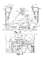
- FIG 3 is a schematic view of a teleoperated system 400 in accordance with another embodiment of the invention.
- Figure 4 shows the teleoperated system 400 during operation by the user 124.
- the teleoperated system 400 includes the teleoperable device 110 and the haptics device 120 as described above with reference to Figures 1 and 2 .
- the teleoperated system 400 also includes a motion capture system 420 having a processing unit 410 coupled to a plurality of cameras 424.
- the teleoperable device 110 is positioned within a control (or capture) volume 422 monitored by the motion capture system 420.
- the teleoperable device 410 may be a vehicle, such as a manned or unmanned aerial vehicle (UAV), a ground vehicle, a water-based vehicle, a manufacturing robot, or any other type of controllable device. Furthermore, the teleoperable device 110 may be powered by any suitable energy source, including battery, solar, gas, and fuel-cell powered devices.
- UAV unmanned aerial vehicle
- the teleoperable device 110 may be powered by any suitable energy source, including battery, solar, gas, and fuel-cell powered devices.
- the processing unit 410 may include a motion processing PC 402, and a camera data collection unit 404.
- the camera data collection unit 404 may be configured to collect real-time image information from the motion capture cameras 424, process the data, and transmit the information to the motion processor 402.
- the processing unit 410 is coupled to an application computer (or analysis and display component) 450 via a datalink 452 ( e . g . an Ethernet connection), and a display 454 is coupled to the application computer 450.
- a datalink 452 e . g . an Ethernet connection
- Running on the application computer 450 is a control program 413 that may be configured to receive input signals from the haptics device 120 and the processing unit 410, and to output suitable control signals to the teleoperable device 110 for movement, stabilization, and recovery from external disturbances via a communications component 456.
- one or more of the processor unit 410, the motion processor 402, and the application computer 450 can be combined.
- the application computer 450, or another environment monitoring computer, can be used to display position, orientation, and other telemetry data of the teleoperable device 110. For example, desired trajectory as well as the actual trajectory can be plotted in near real-time. Other obstacles and constraints 460 can also be displayed, as well as derived data from the control or measurement systems.
- the communications component 456 is an RC transmitter, however, in alternate embodiments, the communication component 456 may communicate with the teleoperable device 110 using any suitable communication method, including, for example, the Bluetooth ® short range wireless communication standard established by Bluetooth SIG, Inc. of Bellevue, Washington, the 802.11 wireless communication standard developed by the Institute of Electrical and Electronics Engineers, or any other suitable communications standards or protocols.
- a converter 458 e . g . an RC signal converter
- the motion capture cameras 424 of the motion capture system 420 are operatively distributed about the control volume 422, and are configured to monitor the positions and movements of a plurality of retro-reflective markers 426 disposed on the teleoperable device 110.
- the retro-reflective markers 426 which reflect light back to the source (in this case, the motion capture cameras 424 which can carry their own light source), can be comprised of various shapes, including tape, spheres, semi or half spheres, or any other suitable shapes.
- the motion capture cameras 424 may operate in the visible portion of the spectrum, however, in alternate embodiments, devices that operate in other portions of the spectrum (e . g . near infrared, infrared, etc.) may be used.
- the motion capture cameras 424 are configured to monitor the retro-reflective markers 426 and to export the positions of the retro-reflective markers 426 to the processing unit 410 in real-time.
- the position and orientation of the teleoperable device 110 may then be determined by the application computer 450.
- the motion capture cameras 424 may internally process the measured marker position data to derive position and orientation data of the teleoperable device 110, and may output the position and orientation data of the teleoperable device 110 to the application computer 450.
- Embodiments of teleoperated systems and methods having a motion capture system 420 advantageously provide the ability to perform remotely piloted, closed-loop haptic feedback.
- a total of six motion capture devices 424 are distributed about an approximately room-sized control volume 422 ( e . g . 25' x 25' x 10') and are configured to provide sub-millimeter position accuracy of the positions of the retro-reflective markers 426 at refresh rates of up to 500 Hz.
- the motion capture devices 424 include correlated motion measurement systems having sub-centimeter positional accuracies, update frequencies of at least 20 Hz, and latency periods of 1/20th second or less.
- the motion capture system 420 may provide six degree-of-freedom motion tracking of the teleoperable device 110 in approximately real-time to enable closed-loop feedback control of the position, movement, and stabilization characteristics of the teleoperable device 110.
- any suitable number of motion capture devices 424 e . g . two or more
- the control volume 422 may be scaled up or down to any desired size.
- the motion capture devices 424 may be configured to provide any suitable or desired resolution and operational frequency.
- an update rate of 50 Hz and accuracy of 1 mm was found to provide an electrical RC helicopter system as shown in Figure 3 with a mass of 240g, stable control and sufficiently fast recovery from external disturbances.
- Suitable motion capture devices 424 that may be used in the motion capture system 420 include those devices commercially available from Vicon Limited of Oxford, UK, as well as motion capture systems commercially available from Motion Analysis Corp. of Santa Rosa, California. Additional details and alternate embodiments of suitable motion capture systems are described in copending, commonly owned U.S. Patent Application No. 11/459,631 filed July 24, 2006 and entitled "Closed-Loop Feedback Control Using Motion Capture Systems," which patent application published as US 20080125896A1 on May 29, 2008 .. Additional information can be found in the research paper: Troy, J.J., Erignac, C.A., Murray, P. "Closed-Loop Motion Capture Feedback Control of Small-Scale Aerial Vehicles", AIAA Infotech@Aerospace Conference, May 2007 .
- a virtual environment may be created to simulate various aspects of the actual environment (e . g . the control volume 422) in which the teleoperable device 110 is to be operated.
- Such a virtual environment may be modeled on the application computer 450 and may be used by the control program 413 for various purposes, including providing haptic feedback to the user 124 via the haptics device 120.
- Figure 4 shows the display of a virtual environment 415, a haptics processing PC 451, and the haptics device 120.
- Software 416 running on the haptics processing PC 451 uses a physics-based simulation of the controlled vehicle and other static or moving objects in the 3D virtual environment 415.
- the functions of the haptics PC 451 can also be handled by the main application computer 450, when enough processing power is available on the application computer 450.
- Position and orientation information from the vehicle tracking system in the real environment was integrated with the physics-based simulation data using the multi-agent virtual coupling technique shown in Figure 9 .
- haptics application software calculates the necessary reaction control forces based on user inputs.
- Some embodiments of the invention use a full 3D model simulation in a physics-based environment, which may be of the type generally used for a digital preassembly analysis.
- geometric constraints can be created by using three dimensional (3D) models in the virtual environment.
- One or more objects (or obstacles) 460 existing in the real environment may be modeled and imported into the virtual environment.
- Wall and ceiling constraints can be included to define the extent of motion within an indoor environment.
- Artificial moving geometry can also be created that doesn't have a physical counterpart, such as virtual obstacles or the area directly above and below another helicopter ( e . g . to avoid disturbances due to air flow generated by the rotors).
- the geometry "seen" by one helicopter to be different than the geometry seen by another.
- a dynamically adjustable proximity field that extends around one or more stationary and moving objects can be modeled to provide additional clearance volume around such objects.
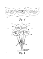
- Figure 5 shows a plurality of teleoperable devices 110, each having a proximity field 180, in accordance with an embodiment of the invention.
- the proximity fields 180 may advantageously be used as contraints by the teleoperated system to prevent collisions with obstacles and other vehicles.
- Figure 6 shows a plurality of teleoperable devices 110 in accordance with one embodiment of the invention.
- a proximity field 180 surrounds each teleoperable device 110, and each teleoperable device 110 is virtually connected to a virtual coupling point 182.
- Figure 7 shows a plurality of teleoperable devices 110, each having an associated proximity field 180, and each virtually coupled to an attachment point 184 on a virtual constraint element 186.
- the virtual constraint element 186 can be rigid, flexible, and/or branched, and is typically controlled through a virtual coupling point 188 which is attached to the haptic device.
- the teleoperable devices 110 of Figures 6 and 7 may be able to move relative to each other, but will not collide with each other due to the proximity fields 180 extending around each device 110.
- the teleoperable devices 110 of Figures 6 and 7 may be controllably moved by a teleoperated system as a unit.
- the system may controllably move the plurality of teleoperable devices 110 by controlling the movement of the virtual coupling point 182, while in the embodiment shown in Figure 7 , the system may controllably move a virtual coupling control point 188 located, for example, anywhere on the virtual member 186.
- the teleoperable devices 110 may be commanded to move independently of one another, or alternately, two or more of the teleoperable devices 110 may be commanded to move in a coordinated manner, such as in flocking or swarming movements. Particular embodiments of coordinated movements of a plurality of vehicles are described more fully, for example, in Beyond Swarm Intelligence: The Ultraswarm, presented at the IEEE Swarm Intelligence Symposium by Holland et al., June 8, 2005 .
- FIG. 6 One particular aspect of this type of swarm control is the virtual branching structure that can be used at the virtual coupling control point 182 ( Figure 6 ) and 188 ( Figure 7 ).
- all teleoperable devices 110 may use the same virtual coupling point 182 with proximity fields 180 providing separation, as described above.
- the proximity fields 180 touch and move relative to each other (like the surfaces of the balloons) but the teleoperable devices 110 inside stay safely away from each other.
- desired offset positions are specified. Using the balloon analogy again, this would be similar to attaching the strings to a board ( e . g . virtual member 186 of Figure 8 ) such that moving the board moves all the balloons, while maintaining specified relative spacing.
- the branching concept allows vehicles or other teleoperable devices to be configured in any type of formation, but still provides for relative movement and a group connection to the virtual coupling control point 188 for haptic feedback.
- a linear array could be specified to allow the formation to move through a narrow opening, or a widely dispersed configuration could be specified to allow maximum area coverage.
- the branching element itself can be a variable function with adjustable position constraints controlled by other algorithms.
- the virtual coupling point 182 could be placed at the "head" of an articulated array and used to lead the formation through a convoluted narrow pathway. All contact and inertia forces generated by each vehicle in these multi-vehicle configurations are transmitted through the virtual coupling control point 182 or 188 to the haptic device. This allows the user to receive simultaneous force feedback from all controlled vehicles.
- the improved teleoperation capabilities of the haptic-enabled feedback environment described herein can be enhanced to work with the concept of adjustable autonomy, which is the ability to move seamlessly between fully human controlled teleoperation and fully autonomous vehicle operation.
- the real-time simulation environment is the common element bridging human teleoperation with control provided by autonomous agents. Geometric constraints and autonomous actions will both work through the virtual coupling connection to the remote vehicle or device.
- the virtual environment and simulated dynamics may be modeled using the commercially available Voxmap PointShell (VPS) software development toolkit (SDK) developed by The Boeing Company.
- VPS Voxmap PointShell
- SDK software development toolkit
- the VPS libraries enable fast collision / proximity detection and reaction force generation desirable for haptics simulations.
- the VPS physics-based simulation engine uses second order dynamics models to calculate realistic object motion, and runs at a real-time update rate of 1000Hz. This generation process is called haptic force rendering.
- Control and force feedback to and from the teleoperable device 110 and the haptics device 120 is provided by virtual coupling, including the use of multi-degree-of-freedom spring-damper elements, as described above with reference to Figures 1 and 2 .
- the positions defined by the motion capture system 420, and closed-loop feedback control algorithms described in the above-referenced Haptics-e publication by McNeely et al. can be treated in a similar manner to a virtual coupling point attached to the haptics handle 122.
- the teleoperable device 110 virtual coupling concept may be an extension of the multi-user interaction techniques described in the Haptics-e publication by McNeely et al. ( Figure 1 ).
- motion forces applied to any I/O component of the system 400 may be transmitted to other I/O components in a bilateral force feedback scheme, and each I/O component may see other I/O components as peers with similar I/O capabilities.
- the simulation environment described above may be suitably used for generating haptic forces for the simulated (or proxy) device 112 (see Figure 1 ) which are transmitted to both the haptics handle 122 and the teleoperable device 110 through virtual couplings 130, 136.
- any contact, inertia, or constraints in the virtual environment may affect the simulated device 112 and are transmitted to the user 124 and the teleoperable device 110.
- the motion of the haptics handle 122 by the user 124 moves the simulated device 112 which also moves the teleoperable device 110, and vice versa.
- the state conditions of the components connected by virtual couplings 130, 136, and the position data provided by the motion capture system 420, are provided to a device controller update loop of the program 413.
- the system 400 uses TCP or UDP network sockets to communicate between the tracker processing PC 402 and the application PC 450.
- the control software running on PC 450 computes and sends actuator commands to the teleoperable device 110 through the communication component 456.
- the haptic device 120, haptics software 416, and virtual environment software 415 are also running on PC 450.
- a variation of the system configuration shown in Figure 3 allows the haptic device 120 to be connected to a different computer, such as computer 451 ( Figure 4 ), using the same type of socket connections. Since haptics computations can be quite demanding, using this second method may advantageously provide additional processing capability for situations where a single PC doesn't have enough processing resources to handle the full work load.
- the handle 122 of the haptics device 120 may in some embodiments be analogous to a 3D version of a flight control "stick" in real airplanes.
- the kinesthetic and tactile feedback of the haptics device 1200 may also be similar to the feedback of an airplane control stick, except the haptics handle 122 may have the additional ability to transmit vertical motion.
- the teleoperable device 110 is a helicopter
- a separate helicopter collective pitch controller may not be needed, as moving the handle 122 vertically may serve to move the helicopter vertically.
- the haptics device 120 may directly control position, where as a flight control stick on an airplane typically controls rate. Alternately, the haptics device 120 may be configured to control rates if desired.
- oscillations and vibrations can be felt through the haptic handle 122, and other tactile events, like a "stick shaker" algorithm, can be programmed to provide additional information.
- Haptic input control may be especially advantageous for control of holonomic or near-holonomic vehicles, such as a helicopter.
- a vehicle is considered to be holonomic if the controllable degrees of freedom are equal to the total degrees of freedom.
- Helicopters are considered holonomic in terms of the translational motions.
- the helicopter translational motions map to the translational motion of the handle (or end effector) 122 of the haptics device 120 having three degrees-of-freedom (DOF) in Cartesian space.
- Devices 120 such as the articulated arm shown in Figure 2 may be well-suited for this purpose.
- control methods include direct control and fly-by-wire control.
- direct control methods specific motions of flight control actuators are commanded directly by the operator. This often requires substantial piloting skill and experience since stable and efficient operation may depend on detailed and intuitive knowledge of the flight characteristics of the vehicle.
- Fly-by-wire control methods reduce the need for specific stabilizing commands by the pilot by providing a computer that specifies the actual positions of the flight control actuators based on desired vehicle motion specified by the pilot. The computer may also provide flight envelope protection. An operational understanding of the vehicle by the pilot is still desirable, but less skill at manipulation of the flight control actuators is typically needed.
- Embodiments of the invention may be implemented in teleoperated systems that use either direct control or fly-by-wire control systems, wherein forces from the vehicle dynamics are presented to the operator through a haptic force feedback device.
- Relatively low-level feedback of the aircraft's motions is available to the operator, providing a more intuitive understanding, or "feel", of the vehicle dynamics.
- the high level commands, which set the goal positions for motion can be provided by human operators ( i.e ., teleoperation) or by path planning software (like the potential field approach).
- Boundary constraints and flight envelope protection can be added to provide additional fly-by-wire capabilities to the teleoperation control mode.
- embodiments of teleoperated systems having motion capture systems provide the ability to perform remotely piloted, closed-loop haptic feedback.
- the application computer 450 operatively communicates with the teleoperable device 110 via the communication component 456, which may use a wireless link, wire-based link, fiber-optic link, or any other suitable type of communication link.
- the communication component 456 communicates signals and data between the application computer 450 and the teleoperable device 110.
- the application computer 450 may be configured to receive video, sensor signals, and other telemetry directly from the teleoperable device 110, and to transmit appropriate command signals directly to the teleoperable device 110.
- the control program 413 implemented on the application computer 450 may perform a variety of functions associated with monitoring and controlling the teleoperable device 110.
- the application computer 450 may include one or more programmable hardware components configured to perform one or more of these functions.
- the control program 413 and the application computer 450 could be combined by programming the control application algorithm into firmware.
- the application computer 450 causes appropriate command signals to be transmitted to one or more teleoperable devices 110, directing the one or more teleoperable devices 110 to perform desired activities or functions.
- the teleoperable device 110 is a flight vehicle
- the command signals may direct the flight vehicle to fly in a desired flight path and to collect desired information using on-board sensors.
- a ground or water-based vehicle may be directed to traverse a desired path, collect information, or perform other desired activities.
- the teleoperable devices 110 may be commanded to move independently of one another, or alternately, two or more of the teleoperable devices 110 may be commanded to move in a coordinated manner, such as in flocking or swarming movements.
- position and orientation information is sent to the command and control program 413 or other suitable control application or component.
- the position and orientation data provided by the motion capture processing system 410 are differentiated to get velocity and angular velocity (both of which may also be filtered to reduce noise) for each degree-of-freedom.
- Position, orientation, linear and angular velocity data is then converted into vehicle coordinates (by using 4 x 4 homogeneous transformation matrix multiplication) and used to calculate error signals, which are then multiplied by feedback gain values, and then used to generate the actuator control values for the actuators of the teleoperable device 110.
- the actuator control values determined by the control application may be converted into a format needed by the communication device 456 prior to transmission to the teleoperable device 110 by the converter 458.
- the converter 458 is an analog 72 MHz RC (remote control) transmitter having a "trainer" port which connects to the application computer 450 using a USB or serial connection.
- a USB-based, pulse-position-modulation (PPM) servo controller converter may be used for PC (personal computer) to RC data conversion, such as those converters commercially available from TTI, Inc. of Fremont, California.
- any suitable analog or digital transmitter devices and converters may be used.
- the motion capture system 420 tracks the positions of the retro-reflective markers 426 on the teleoperable device 110 and generates a representation of the position and orientation (quaternion or 4x4 homogeneous transformation matrix) of a particular grouping of retro-reflective markers 426.
- the various controllable devices and other objects in the environment are identified by the motion capture system 420 based on the unique pattern of retro-reflective marker placements on each object.
- control software 413 running on the application computer 450 compares the position and orientation feedback information with the desired positions of the teleoperable device 110, determines the desired actuator inputs for controlling the movement of the teleoperable device 110 and causes appropriate command signals to be transmitted to the teleoperable device 110 via the communication component 456 to controllably adjust (or maintain) the positions and velocities of the teleoperable device 110 in its desired positions or along its desired headings at the desired rates of movement.
- the control signals may be generated by the user 124 via the haptics device 120, or a combination of user-generated and control software 413 generated control signals may be used.
- the motion capture system 420 provides the teleoperated system 400 with the position and orientation information needed for a closed-loop feedback control capability for adjusting the positions and movements of the teleoperable device 110. More specifically, the motion capture system 420 may advantageously provide position and orientation feedback information that enables the application computer 450 to determine and control not only Cartesian positions (x, y, z), but also orientation (roll, pitch, yaw) control commands for proper control and stabilization of the teleoperable device 110.
- the system 400 described above and shown in Figures 3 and 4 is depicted as being used in an indoor environment; however, operation in other environments is also possible.
- the system 400 may be suited to operate in some outdoor environments.
- other types of position tracking systems can be used in place of the camera-based motion capture system 420 to further facilitate outdoor implementations.
- acceleration data from on-board accelerometers or inertial measurement units (IMUs) and GPS, larger outdoor systems can be implemented.
- IMUs inertial measurement units
- Embodiments of systems and methods in accordance with the present invention may provide significant advantages over the prior art.
- the haptic feedback for teleoperation of devices provides tactile and kinesthetic cues that indicate the device's reaction to user inputs.
- the implementation of improved teleoperation processes in accordance with the present disclosure will result in higher performance for teleoperable devices, including remotely piloted vehicles, due to increased information flow through tactile and kinesthetic channels of the human operator.
- This performance increase will enable off-board operators to re-claim some of the precise control abilities available to an onboard operator of such a device, ( e . g . a pilot onboard an aircraft) which may include: increased safety, faster reaction times to unexpected disturbances, and the precise flying ability for helicopter pilots needed to hook and lift objects.
- haptic feedback helps return the "seat-of-the-pants" flying abilities to the remote pilot.
- Embodiments of systems and methods in accordance with the present invention may also provide a well structured development environment for testing various types of control techniques using force feedback in a laboratory setting.
- embodiments of systems and method having motion capture systems advantageously provide the above-noted abilities and performance enhancements via close-loop, haptic feedback control systems.
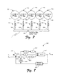
- Figure 8 is a diagram of a control method 300 for controlling one or more vehicles 410 using the control system 400 of Figures 1 through 3 .
- the method 300 includes providing a high-level command request, which may come from a human operator, an autonomous agent, or another higher-level source.
- the command requests may come from a user interface, such as a haptic device, 120.
- the desired high-level command request is converted to a properly formatted vehicle command ( e . g . state vector Xset of Figure 8 ).
- a closed-loop feedback control loop begins when the vehicle-formatted command request, which is determined by a function of the desired and measured states, is sent to the vehicle ("Plant" in Figure 8 ).
- the vehicle-formatted command request which is determined by a function of the desired and measured states
- the vehicle is sent to the vehicle ("Plant" in Figure 8 ).
- one or more positions and orientations of the one or more vehicles 410 are acquired. Initially, the one or more positions and orientations may be known, such as from inputs or initial conditions during start up of the method 300, or may be determined by the position reference system 420.
- the control loop is closed by feeding the measure position and orientation information back to the start of the process.
- the control loop is the implementation of one or more of the control methods described above, and is responsible for maintaining the desired trajectory and recovering from unexpected disturbances.
- a method called a proportional, integral, derivative (PID) control is used.
- This method applies a set of feedback control gains (K p , K i , K d , blocks 312 in Figure 8 ) to the state vector errors (Xerr of Figure 8 ) to determine the control signals sent to the controlled device (or Plant) 410.
- the method 300 determines the difference (Xerr) between the desired positions and the values measured by the motion capture system 420.
- the method 300 determines the difference between the desired velocities and the velocities determined by differentiating (block 314) the position values measured by the motion capture system 420.
- Appropriate actuator control signals are determined by multiplying the error values leaving the summing junctions 310 and 311 by the feedback gains (K p , K i , K d ) at blocks 312. Additional embodiments may use other control techniques that use the current system state or predicted state for feedback control (e . g ., Pole-placement, LQR). In addition, data multiple types of position, velocity, or acceleration measurement systems could be combined with the motion capture data to give a more accurate estimate of the state ( e . g ., Kalman filter). Next, the determined actuator control signals may be converted to RC (remote control) signals, and the RC signals may be transmitted to the vehicle 410.
- RC remote control
- Method 300 can be run simultaneously to control one or more additional controlled devices from one or more application computers 450 ( Figure 3 ).
- the measured position and derived velocity data may also be sent to a virtual simulation environment (416) for use in haptic force generation.
- the vehicle 410 may move in response to the control signals, and the positions and velocities of the vehicle 410 are monitored and measured by the position reference system 420.
- the method 300 then returns to where the measured positions and velocities are updated and the above-described actions are repeated indefinitely. In this way, the method 300 uses the motion capture system 420 to provide position and orientation data for closed-loop feedback control of the controlled device 410.
- program modules include routines, programs, objects, components, data structures, and so forth for performing particular tasks or implement particular abstract data types.
- program modules and the like may be executed as native code or may be downloaded and executed, such as in a virtual machine or other just-in-time compilation execution environment.
- functionality of the program modules may be combined or distributed as desired in various embodiments.
- An implementation of these modules and techniques may be stored on or transmitted across some form of computer readable media.
- FIG 9 is a schematic view of a haptics-enabled teleoperated system 600 in accordance with another embodiment of the invention. It will be appreciated that several of the components of the system 600 are substantially the same as the corresponding components described above with respect to Figures 1 through 4 , and therefore, for the sake of brevity, such components will not be described in detail again.
- the teleoperated system 600 is configured to simultaneously monitor and control a plurality of controllable devices 610 using a corresponding plurality of haptics controllers 620.
- the motion capture system 420 monitors a control volume 422 that includes a ground vehicle 610A, a blimp (or lighter-than-air vehicle) 610B, and a plurality of helicopters 610C, robot arms 610D, and other controllable objects 610E.
- a control volume 422 that includes a ground vehicle 610A, a blimp (or lighter-than-air vehicle) 610B, and a plurality of helicopters 610C, robot arms 610D, and other controllable objects 610E.
- any other suitable controllable devices may be used.
- other types of position and orientation tracking may be used.
- At least one of the controllable devices 610 is a flying crane platform.
- Embodiments of haptics interaction methods allow precise control of such a lifting platform without the extensive training needed to operate an actual helicopter.
- One of the difficulties with such lifting platforms is hooking a payload.
- a teleoperated interface in accordance with the present invention would make this task much more efficient.
- Smaller flying cranes are another primary application of this technology, including devices for performing tasks like lifting debris from a road or moving parts in a factory.
- each of the controllable devices 610 is configured with a plurality of retro-reflective markers 426 that are monitored and tracked by the motion capture system 420 as described above.
- the retro-reflective markers 426 (or other suitable marking devices) may be placed in different patterns on the controllable devices 610 to enable the motion capture system 420 to identify and distinguish between the individual controllable devices 610.
- an application computer 650 includes a plurality of application processors 652 that are coupled to the motion capture processing computer 402 via a network switch 653.
- Each application processor 652 receives the outputs from the motion capture processing computer 402 (e . g . the position and orientation data provided by the motion capture system 420), performs any necessary filtering, buffering, signal amplification, or other desired functions, and transmits the control signal data to a corresponding converter 655.
- the converter 655 performs the conversion of the control signals to a format suitable for transmission to the controllable devices 610 as described above, and communicates the properly formatted control signals to the corresponding transmitter 657 for transmission to the corresponding controllable devices 610 by way of the transmitter's "trainer" port.
- transmitter 657 can be replaced by other types of wireless communications equipment (e . g ., 802.11, Bluetooth).
- the motion capture information provided by the motion capture system 420 may be broadcast to one or more control components of the system 600, such as the software 413 implemented on the application computer 450, for determination of the range and speed of each controllable device 610, including any actions that may be needed to avoid collisions.
Landscapes
- Engineering & Computer Science (AREA)
- Physics & Mathematics (AREA)
- Aviation & Aerospace Engineering (AREA)
- Radar, Positioning & Navigation (AREA)
- Remote Sensing (AREA)
- General Physics & Mathematics (AREA)
- Automation & Control Theory (AREA)
- Acoustics & Sound (AREA)
- Human Computer Interaction (AREA)
- User Interface Of Digital Computer (AREA)
- Control Of Position, Course, Altitude, Or Attitude Of Moving Bodies (AREA)
- Motorcycle And Bicycle Frame (AREA)
Abstract
Description
- A variety of different devices can be operated remotely, including remotely-controlled air, water, and land-based vehicles, manufacturing robots, and other suitable devices. In general, such teleoperable devices require a control system that enables a human operator or a machine controller to monitor movements of the vehicle and issue appropriate control signals to cause the device to move as desired. Clearly, a wide variety of controllable devices need control systems to effectuate the desired controllable movement. However, prior art teleoperation systems and methods may not provide the desired controllability of such devices. Although prior art systems and methods have achieved desirable results, there is room for improvement.
- The present invention is directed to systems and methods for haptics-enabled teleoperation of devices, including remotely-controlled air, water, and land-based vehicles, manufacturing robots, and other suitable teleoperable devices. Embodiments of the invention may advantageously provide improved control of teleoperable devices in comparison with prior art systems and methods. For example, in some prior circumstances, the ability of an operator to control a teleoperable device may be diminished because the operator does not physically experience a feedback of forces and accelerations that the operator would experience if she were positioned onboard the teleoperable device. In the case of an aircraft, an experienced onboard pilot can often perform a landing without using instrumentation by relying on visual input and by feeling feedback (e.g. forces and accelerations) produced by the motions of the aircraft. Physically sensing acceleration forces may be particularly important to a helicopter pilot.
- In one embodiment, a system for teleoperation of a vehicle comprises a control component configured to provide position and orientation control with haptic force feedback of the vehicle based on a position measurement of the vehicle and configured to function in a closed-loop feedback manner. In a particular embodiment, the position measurement may include six degree-of-freedom position data provided by a motion capture system to the control and/or haptic I/O components of the application. The system may also use differences in position and/or velocity between the vehicle and a haptic I/O device for feedback control.
- In another embodiment, a method of operating a teleoperable device by directly controlling least one of position and orientation of the teleoperable device includes providing an input to a haptics device virtually coupled to the teleoperable device; providing at least one control signal to the teleoperable device based on the input, the at least one control signal being configured to directly control at least one of position and orientation of the teleoperable device; measuring at least one state characteristic of the teleoperable device; and providing a haptics output to an operator based on at least one of a response from the teleoperable device and the at least one state characteristic.
- In a further embodiment, a system for operating a teleoperable device by controlling at least one of position and orientation of the teleoperable device includes a haptics device coupleable to the teleoperable device and configured to receive an operator input; and a sensing system operatively coupled to the haptics device and configured to measure at least one state characteristic of the teleoperable device, wherein the haptics device is further configured to provide at least one control signal to the teleoperable device, the at least one control signal being configured to directly control at least one of position and orientation of the teleoperable device based on at least one of the operator input and the at least one state characteristic.
- The features, functions, and advantages that have been discussed can be achieved independently in various embodiments of the present invention or may be combined in yet other embodiments further details of which can be seen with reference to the following description and drawings.
- Embodiments of the present invention are described in detail below with reference to the following drawings.
-
Figure 1 is a schematic view of a teleoperated system including a teleoperable device, a haptic force feedback I/O device, and a representation of the mathematical system model in accordance with an embodiment of the invention; -
Figure 2 is an image (perspective view) of a haptics device of the teleoperated system ofFigure 1 ; -
Figure 3 is a haptics-enabled teleoperated system incorporating a motion capture tracking system in accordance with another embodiment of the invention; -
Figure 4 is an image of a teleoperable device, and haptic device, and view of the virtual environment ofFigure 3 in operation; -
Figure 5 shows a plurality of teleoperable devices, each having a virtual contact proximity field, in accordance with another embodiment of the invention; -
Figures 6 and7 show a plurality of teleoperable devices controlled by a single agent in accordance with further embodiments of the invention; -
Figure 8 is a schematic representation a feedback control system used in one embodiment of the invention; and -
Figure 9 is a schematic view of a haptics-enabled teleoperated system with multiple teleoperated vehicles control through multiple haptic interfaces in accordance with another embodiment of the invention. - The present invention relates to systems and methods for haptics-enabled teleoperation of devices, including such controllable devices as flight vehicles, water and land-based vehicles, manufacturing vehicles and systems, and any other suitable controllable device or system. Many specific details of certain embodiments of the invention are set forth in the following description and in
Figures 1-9 to provide a thorough understanding of such embodiments. One skilled in the art, however, will understand that the present invention may have additional embodiments, or that the present invention may be practiced without several of the details described in the following description. - In general, embodiments of the present invention provide feedback of a teleoperable device's motion to an operator via a haptics-enabled feedback system. The operator receives feedback from the teleoperable device which may enable the operator to control the device (e.g. aircraft) using both visual and physical stimuli, thereby providing improved controllability in comparison with prior art systems. In the case of teleoperable aircraft, embodiments of methods and systems in accordance with the present invention may be implemented in either fly-by-wire control systems or direct control systems as desired.
- The teleoperation control capabilities provided by embodiments of the invention may be further extended by adding a haptic force feedback interface and a real-time simulation environment to the application. These aspects may provide an intuitive and efficient method for precise control of remotely piloted systems. The low level feedback of the device's motions is available to the operator, which may provide an intuitive understanding or "feel" of the dynamics of the teleoperable device. A basic concept of haptics-enabled embodiments described herein involves connecting force feedback calculations to a control loop through virtual coupling and proxy objects, which may be defined in a real-time simulation environment running simultaneously with a control system. This type of force feedback enables applications that require precise motion control. The intuitive feedback provides a more natural interface that results in more efficient operation of the vehicle or device, and also gives the remote pilot or operator a faster reaction time to unexpected disturbances.
-
Figure 1 is a schematic view of ateleoperated system 100 having ateleoperable device 110 in accordance with an embodiment of the invention. In this embodiment, theteleoperable device 110 is a helicopter, however, in alternate embodiments, theteleoperable device 110 may be any type of vehicle, robot, machine, or other suitable device. In one particular embodiment, theteleoperable device 110 is a modified version of an E-flite Blade CX 180 RC helicopter commercially available from Horizon Hobby, Inc. of Champaign, Illinois. - Control and force feedback of the
teleoperable device 110 is provided by a haptics device (or handle) 120. A firstvirtual coupling 130 operatively couples thehaptics device 120 to aproxy object 112, and a secondvirtual coupling 136 operatively couples theproxy object 112 to theteleoperable device 110. In this embodiment, each of the first and secondvirtual couplings freedom spring element -
Figure 2 is a perspective view image of an embodiment of thehaptics device 120 ofFigure 1 . In general, haptics devices are interfaces for the sense of touch. For haptic teleoperation, this interface may be bi-directional, meaning that auser 124 provides position or force input to thesystem 100 and software controlling thehaptics device 120 provides a position response by moving components (e.g. motors, actuators, etc.) in thehaptics device 120. Resistance to this motion by theuser 124 produces the force feedback. With haptic interaction, theuser 124 may be afforded more than just another type of input device. Haptics devices provide a high-bandwidth channel for additional information flow to the user from the system or application. This type feedback of information is not available from input-only devices like joysticks. The interaction with thehaptics device 120 is similar to what would be felt by the user if the actual vehicle was being held and manipulated by theuser 124. The forces can be scaled so that larger or smaller vehicles can be controlled by the same type of haptic interface. The forces felt by the user in this type of teleoperation are computed based on a combination of the inertia forces generated by vehicle accelerations, and by constraint forces generated in the physics-based virtual environment. The advantage of this type of feedback is that it allows the user to perceive additional information about the vehicle's condition or the environment in which it is operating. Some examples of this type of feedback include: - Inertia forces provide information about magnitude and direction of acceleration
- Contact and near-contact forces (proximity) may be represented as a barrier
- Headwinds may be interpreted as a direction specific resistance to motion
- Turbulence may be transmitted as a vibration force
- Vehicle sluggishness due to low battery power may be felt as a resistance to motion
- Increased mass due to lifting an object may be felt as an increased vertical resistance
- In the particular embodiment shown in
Figure 2 , thehaptics device 120 is a bi-directional force feedback device in the form of an articulated robot arm, called a PHANTOM® haptics device, which is commercially-available from SensAble Technologies, Inc. of Woburn, Massachusetts. Of course, in alternate embodiments, any other suitable embodiments of haptics devices may be used. Thehaptic device 120 includes ahandle 122 having up to six inputs: three Cartesian translations (x, y, z) and three rotations (roll, pitch, yaw). Thehaptic device 120 may output forces in three Cartesian dimensions. In applications where a six degree-of-freedom output haptic device is used, additional rotation forces (torques) may also be felt through thehandle 122, giving theuser 124 roll, pitch, and yaw torque feedback. - In operation, motion forces applied to any component (e.g. the
haptics device 120, theteleoperable device 110, and the dynamics elements of the physics-based simulation environment 416) of thesystem 100 will be transmitted to other components of thesystem 100. This two-way interaction is called bilateral force feedback for a two I/O port system. In the embodiment shown inFigures 1 and 2 , both thehaptics device 120 and theteleoperable device 110 are seen by the other as a peer with similar I/O capabilities. - In one embodiment, the
user 124 operates theteleoperated system 100 by moving (i.e., translating and rotating) thehandle 122 of thehaptics device 120, while watching either a simulation on a screen or live motion of theteleoperable device 110. Moving theteleoperable device 110 from one place to another involves a scaled mapping of the motion of thehaptics device 120 to the motion of theteleoperable device 110. In some embodiments, position control of thehandle 122 of thehaptics device 120 can be indexed (repositioned) by pressing a stylus button (not shown) on thehandle 122. The indexing is similar in concept to picking up and repositioning a mouse to get a more useful position on a mouse pad. Indexing can also be applied to relative orientation. - Movement of the
haptics device 120 produces a corresponding movement of theproxy object 112 through the firstvirtual coupling 130, which in turn produces a movement of theteleoperable device 110 through the secondvirtual coupling 136. The details of implementing the first and secondvirtual couplings virtual couplings - For example, as disclosed in the above-referenced paper entitled "Six Degree-of-Freedom Haptic Rendering Using Voxel Sampling," in some embodiments, the
virtual couplings - In such a dynamic model, a net force and torque on the dynamic object may be a sum of contributions from a spring-damper system conceptually placed in a virtual scene and coupled between the haptic device and the dynamic object. The real haptic device controls the position and orientation of its virtual counterpart, and influences the spring's displacement which generates a virtual force/torque on the dynamic object and an opposite force/torque on the real haptic handle. Spring displacement may also include rotational motion. Spring force may be proportional to displacement, while spring torque may be proportional to an angle of rotation from an equivalent-angle analysis and directed along an equivalent axis of rotation.
- Furthermore, a six degree-of-freedom (6-DOF) spring makes the dynamic object tend to acquire the same position and orientation of the virtual haptic device, assuming that the two objects are initially registered in some manner (e.g. with the center of the haptic device located at the dynamic object's center of mass and the device's main axis aligned with one of the dynamic object's principal axes). The virtual object is assigned mass properties, which may be reflected at the haptic interface as apparent mass that is added to the haptic device's intrinsic inertia. The force and torque equations used are as follows:


where
kT, bT = spring translational stiffness and viscosity
kR, bR = spring rotational stiffness and viscosity
θ = equivalent-axis angle (including axis direction)
v,ω = dynamic object's relative linear and angular velocity. - Spring stiffness may be set to a reasonably high value that is still comfortably consistent with stable numerical behavior at the known time sampling rate. Stiffness and viscosity may be straightforwardly related to obtain critically damped behavior. This model is most valid for a dynamic object having equal moments of inertia in every direction, such as a sphere of uniform mass density, which is typically an acceptable assumption if reflected moments of inertia are not desired or necessary. Assuming equal moments of inertia in every direction typically represents an implicit constraint on the virtual object's mass density distribution, but not on its geometrical shape.
-
Figure 3 is a schematic view of ateleoperated system 400 in accordance with another embodiment of the invention.Figure 4 shows theteleoperated system 400 during operation by theuser 124. In this embodiment, theteleoperated system 400 includes theteleoperable device 110 and thehaptics device 120 as described above with reference toFigures 1 and 2 . Theteleoperated system 400 also includes amotion capture system 420 having aprocessing unit 410 coupled to a plurality ofcameras 424. Theteleoperable device 110 is positioned within a control (or capture)volume 422 monitored by themotion capture system 420. Theteleoperable device 410 may be a vehicle, such as a manned or unmanned aerial vehicle (UAV), a ground vehicle, a water-based vehicle, a manufacturing robot, or any other type of controllable device. Furthermore, theteleoperable device 110 may be powered by any suitable energy source, including battery, solar, gas, and fuel-cell powered devices. - In some embodiments, the
processing unit 410 may include amotion processing PC 402, and a cameradata collection unit 404. The cameradata collection unit 404 may be configured to collect real-time image information from themotion capture cameras 424, process the data, and transmit the information to themotion processor 402. Theprocessing unit 410 is coupled to an application computer (or analysis and display component) 450 via a datalink 452 (e.g. an Ethernet connection), and adisplay 454 is coupled to theapplication computer 450. Running on theapplication computer 450 is acontrol program 413 that may be configured to receive input signals from thehaptics device 120 and theprocessing unit 410, and to output suitable control signals to theteleoperable device 110 for movement, stabilization, and recovery from external disturbances via acommunications component 456. - In alternate embodiments, one or more of the
processor unit 410, themotion processor 402, and theapplication computer 450 can be combined. Theapplication computer 450, or another environment monitoring computer, can be used to display position, orientation, and other telemetry data of theteleoperable device 110. For example, desired trajectory as well as the actual trajectory can be plotted in near real-time. Other obstacles andconstraints 460 can also be displayed, as well as derived data from the control or measurement systems. - In one embodiment, the
communications component 456 is an RC transmitter, however, in alternate embodiments, thecommunication component 456 may communicate with theteleoperable device 110 using any suitable communication method, including, for example, the Bluetooth® short range wireless communication standard established by Bluetooth SIG, Inc. of Bellevue, Washington, the 802.11 wireless communication standard developed by the Institute of Electrical and Electronics Engineers, or any other suitable communications standards or protocols. A converter 458 (e.g. an RC signal converter) may be coupled between theapplication computer 450 and thecommunication component 456 to convert control signals from theapplication computer 450 to a format suitable for transmission to theteleoperable device 110 by thecommunication component 456. - With continued reference to
Figures 3 and 4 , themotion capture cameras 424 of themotion capture system 420 are operatively distributed about thecontrol volume 422, and are configured to monitor the positions and movements of a plurality of retro-reflective markers 426 disposed on theteleoperable device 110. The retro-reflective markers 426, which reflect light back to the source (in this case, themotion capture cameras 424 which can carry their own light source), can be comprised of various shapes, including tape, spheres, semi or half spheres, or any other suitable shapes. - In some embodiments, the
motion capture cameras 424 may operate in the visible portion of the spectrum, however, in alternate embodiments, devices that operate in other portions of the spectrum (e.g. near infrared, infrared, etc.) may be used. Themotion capture cameras 424 are configured to monitor the retro-reflective markers 426 and to export the positions of the retro-reflective markers 426 to theprocessing unit 410 in real-time. The position and orientation of theteleoperable device 110 may then be determined by theapplication computer 450. Alternately, using a priori knowledge of the positions of the retro-reflective markers 426 on theteleoperable device 110, the motion capture cameras 424 (or the processing unit 410) may internally process the measured marker position data to derive position and orientation data of theteleoperable device 110, and may output the position and orientation data of theteleoperable device 110 to theapplication computer 450. - Embodiments of teleoperated systems and methods having a
motion capture system 420 advantageously provide the ability to perform remotely piloted, closed-loop haptic feedback. In one particular embodiment, a total of sixmotion capture devices 424 are distributed about an approximately room-sized control volume 422 (e.g. 25' x 25' x 10') and are configured to provide sub-millimeter position accuracy of the positions of the retro-reflective markers 426 at refresh rates of up to 500 Hz. In another embodiment, themotion capture devices 424 include correlated motion measurement systems having sub-centimeter positional accuracies, update frequencies of at least 20 Hz, and latency periods of 1/20th second or less. - The
motion capture system 420 may provide six degree-of-freedom motion tracking of theteleoperable device 110 in approximately real-time to enable closed-loop feedback control of the position, movement, and stabilization characteristics of theteleoperable device 110. In alternate embodiments, any suitable number of motion capture devices 424 (e.g. two or more) may be used, and thecontrol volume 422 may be scaled up or down to any desired size. Similarly, in alternate embodiments, themotion capture devices 424 may be configured to provide any suitable or desired resolution and operational frequency. In one particular embodiment, an update rate of 50 Hz and accuracy of 1 mm was found to provide an electrical RC helicopter system as shown inFigure 3 with a mass of 240g, stable control and sufficiently fast recovery from external disturbances. The same vehicle was also shown to have stable performance at 20 Hz update rates, but with slower recovery from disturbances. Suitablemotion capture devices 424 that may be used in themotion capture system 420 include those devices commercially available from Vicon Limited of Oxford, UK, as well as motion capture systems commercially available from Motion Analysis Corp. of Santa Rosa, California. Additional details and alternate embodiments of suitable motion capture systems are described in copending, commonly ownedU.S. Patent Application No. 11/459,631 filed July 24, 2006 US 20080125896A1 on May 29, 2008 .. Additional information can be found in the research paper: Troy, J.J., Erignac, C.A., Murray, P. "Closed-Loop Motion Capture Feedback Control of Small-Scale Aerial Vehicles", AIAA Infotech@Aerospace Conference, May 2007. - In some embodiments, a virtual environment may be created to simulate various aspects of the actual environment (e.g. the control volume 422) in which the
teleoperable device 110 is to be operated. Such a virtual environment may be modeled on theapplication computer 450 and may be used by thecontrol program 413 for various purposes, including providing haptic feedback to theuser 124 via thehaptics device 120. -
Figure 4 shows the display of avirtual environment 415, ahaptics processing PC 451, and thehaptics device 120. Software 416 running on thehaptics processing PC 451 uses a physics-based simulation of the controlled vehicle and other static or moving objects in the 3Dvirtual environment 415. In some embodiments, the functions of thehaptics PC 451 can also be handled by themain application computer 450, when enough processing power is available on theapplication computer 450. Position and orientation information from the vehicle tracking system in the real environment was integrated with the physics-based simulation data using the multi-agent virtual coupling technique shown inFigure 9 . - In some aspects, in order for the
haptics device 120 to output the appropriate position/force feedback responses, haptics application software (e.g. that may reside in thehaptics device 120 or in the application computer 450) calculates the necessary reaction control forces based on user inputs. Some embodiments of the invention use a full 3D model simulation in a physics-based environment, which may be of the type generally used for a digital preassembly analysis. - For example, in some embodiments, geometric constraints can be created by using three dimensional (3D) models in the virtual environment. One or more objects (or obstacles) 460 existing in the real environment may be modeled and imported into the virtual environment. Wall and ceiling constraints can be included to define the extent of motion within an indoor environment. Artificial moving geometry can also be created that doesn't have a physical counterpart, such as virtual obstacles or the area directly above and below another helicopter (e.g. to avoid disturbances due to air flow generated by the rotors). Related to this is the option to allow the geometry "seen" by one helicopter to be different than the geometry seen by another.
- In other embodiments, a dynamically adjustable proximity field that extends around one or more stationary and moving objects can be modeled to provide additional clearance volume around such objects. For example,
Figure 5 shows a plurality ofteleoperable devices 110, each having aproximity field 180, in accordance with an embodiment of the invention. The proximity fields 180 may advantageously be used as contraints by the teleoperated system to prevent collisions with obstacles and other vehicles. - Similarly, the haptics and virtual coupling techniques disclosed herein can also be applied to control multiple vehicles from the same input device. For example,
Figure 6 shows a plurality ofteleoperable devices 110 in accordance with one embodiment of the invention. Aproximity field 180 surrounds eachteleoperable device 110, and eachteleoperable device 110 is virtually connected to avirtual coupling point 182. Similarly,Figure 7 shows a plurality ofteleoperable devices 110, each having an associatedproximity field 180, and each virtually coupled to anattachment point 184 on avirtual constraint element 186. Thevirtual constraint element 186 can be rigid, flexible, and/or branched, and is typically controlled through avirtual coupling point 188 which is attached to the haptic device. Theteleoperable devices 110 ofFigures 6 and7 may be able to move relative to each other, but will not collide with each other due to the proximity fields 180 extending around eachdevice 110. - Thus, the
teleoperable devices 110 ofFigures 6 and7 may be controllably moved by a teleoperated system as a unit. In the embodiment shown inFigure 6 , the system may controllably move the plurality ofteleoperable devices 110 by controlling the movement of thevirtual coupling point 182, while in the embodiment shown inFigure 7 , the system may controllably move a virtualcoupling control point 188 located, for example, anywhere on thevirtual member 186. In various aspects, theteleoperable devices 110 may be commanded to move independently of one another, or alternately, two or more of theteleoperable devices 110 may be commanded to move in a coordinated manner, such as in flocking or swarming movements. Particular embodiments of coordinated movements of a plurality of vehicles are described more fully, for example, in Beyond Swarm Intelligence: The Ultraswarm, presented at the IEEE Swarm Intelligence Symposium by Holland et al., June 8, 2005. - One particular aspect of this type of swarm control is the virtual branching structure that can be used at the virtual coupling control point 182 (
Figure 6 ) and 188 (Figure 7 ). In a first or default mode, allteleoperable devices 110 may use the samevirtual coupling point 182 withproximity fields 180 providing separation, as described above. This results in a formation that is analogous to a person holding the strings of several helium balloons in one hand (Figure 6 ). The proximity fields 180 touch and move relative to each other (like the surfaces of the balloons) but theteleoperable devices 110 inside stay safely away from each other. In a branched virtual coupling (Figure 7 ), desired offset positions are specified. Using the balloon analogy again, this would be similar to attaching the strings to a board (e.g.virtual member 186 ofFigure 8 ) such that moving the board moves all the balloons, while maintaining specified relative spacing. - The branching concept allows vehicles or other teleoperable devices to be configured in any type of formation, but still provides for relative movement and a group connection to the virtual
coupling control point 188 for haptic feedback. For example, a linear array could be specified to allow the formation to move through a narrow opening, or a widely dispersed configuration could be specified to allow maximum area coverage. The branching element itself can be a variable function with adjustable position constraints controlled by other algorithms. For example, thevirtual coupling point 182 could be placed at the "head" of an articulated array and used to lead the formation through a convoluted narrow pathway. All contact and inertia forces generated by each vehicle in these multi-vehicle configurations are transmitted through the virtualcoupling control point - Furthermore, the improved teleoperation capabilities of the haptic-enabled feedback environment described herein can be enhanced to work with the concept of adjustable autonomy, which is the ability to move seamlessly between fully human controlled teleoperation and fully autonomous vehicle operation. In this type of unified application, the real-time simulation environment is the common element bridging human teleoperation with control provided by autonomous agents. Geometric constraints and autonomous actions will both work through the virtual coupling connection to the remote vehicle or device.
- In one particular embodiment, the virtual environment and simulated dynamics may be modeled using the commercially available Voxmap PointShell (VPS) software development toolkit (SDK) developed by The Boeing Company. The VPS libraries enable fast collision / proximity detection and reaction force generation desirable for haptics simulations. The VPS physics-based simulation engine uses second order dynamics models to calculate realistic object motion, and runs at a real-time update rate of 1000Hz. This generation process is called haptic force rendering.
- Control and force feedback to and from the
teleoperable device 110 and thehaptics device 120 is provided by virtual coupling, including the use of multi-degree-of-freedom spring-damper elements, as described above with reference toFigures 1 and 2 . In some embodiments, the positions defined by themotion capture system 420, and closed-loop feedback control algorithms described in the above-referenced Haptics-e publication by McNeely et al., can be treated in a similar manner to a virtual coupling point attached to the haptics handle 122. Similarly, in further embodiments, theteleoperable device 110 virtual coupling concept may be an extension of the multi-user interaction techniques described in the Haptics-e publication by McNeely et al. (Figure 1 ). Again, motion forces applied to any I/O component of thesystem 400 may be transmitted to other I/O components in a bilateral force feedback scheme, and each I/O component may see other I/O components as peers with similar I/O capabilities. - It will be appreciated that the simulation environment described above may be suitably used for generating haptic forces for the simulated (or proxy) device 112 (see
Figure 1 ) which are transmitted to both the haptics handle 122 and theteleoperable device 110 throughvirtual couplings simulated device 112 and are transmitted to theuser 124 and theteleoperable device 110. In a similar way, the motion of the haptics handle 122 by theuser 124 moves thesimulated device 112 which also moves theteleoperable device 110, and vice versa. The state conditions of the components connected byvirtual couplings motion capture system 420, are provided to a device controller update loop of theprogram 413. - In some embodiments, such as the one shown in
Figure 3 , thesystem 400 uses TCP or UDP network sockets to communicate between thetracker processing PC 402 and theapplication PC 450. The control software running onPC 450 computes and sends actuator commands to theteleoperable device 110 through thecommunication component 456. Thehaptic device 120, haptics software 416, andvirtual environment software 415 are also running onPC 450. A variation of the system configuration shown inFigure 3 allows thehaptic device 120 to be connected to a different computer, such as computer 451 (Figure 4 ), using the same type of socket connections. Since haptics computations can be quite demanding, using this second method may advantageously provide additional processing capability for situations where a single PC doesn't have enough processing resources to handle the full work load. - The
handle 122 of thehaptics device 120 may in some embodiments be analogous to a 3D version of a flight control "stick" in real airplanes. The kinesthetic and tactile feedback of the haptics device 1200 may also be similar to the feedback of an airplane control stick, except the haptics handle 122 may have the additional ability to transmit vertical motion. In further embodiments wherein theteleoperable device 110 is a helicopter, a separate helicopter collective pitch controller may not be needed, as moving thehandle 122 vertically may serve to move the helicopter vertically. Also, in still other embodiments, thehaptics device 120 may directly control position, where as a flight control stick on an airplane typically controls rate. Alternately, thehaptics device 120 may be configured to control rates if desired. Typically, oscillations and vibrations can be felt through thehaptic handle 122, and other tactile events, like a "stick shaker" algorithm, can be programmed to provide additional information. - Haptic input control may be especially advantageous for control of holonomic or near-holonomic vehicles, such as a helicopter. As used in this disclosure, a vehicle is considered to be holonomic if the controllable degrees of freedom are equal to the total degrees of freedom. Helicopters are considered holonomic in terms of the translational motions. Using embodiments of the invention, the helicopter translational motions map to the translational motion of the handle (or end effector) 122 of the
haptics device 120 having three degrees-of-freedom (DOF) in Cartesian space.Devices 120 such as the articulated arm shown inFigure 2 may be well-suited for this purpose. - In the context of teleoperated aerial vehicles, different embodiments of the invention may use different control methods. For example, main types of control methods include direct control and fly-by-wire control. In direct control methods, specific motions of flight control actuators are commanded directly by the operator. This often requires substantial piloting skill and experience since stable and efficient operation may depend on detailed and intuitive knowledge of the flight characteristics of the vehicle. Fly-by-wire control methods reduce the need for specific stabilizing commands by the pilot by providing a computer that specifies the actual positions of the flight control actuators based on desired vehicle motion specified by the pilot. The computer may also provide flight envelope protection. An operational understanding of the vehicle by the pilot is still desirable, but less skill at manipulation of the flight control actuators is typically needed.
- Embodiments of the invention may be implemented in teleoperated systems that use either direct control or fly-by-wire control systems, wherein forces from the vehicle dynamics are presented to the operator through a haptic force feedback device. Relatively low-level feedback of the aircraft's motions is available to the operator, providing a more intuitive understanding, or "feel", of the vehicle dynamics. The high level commands, which set the goal positions for motion, can be provided by human operators (i.e., teleoperation) or by path planning software (like the potential field approach). Boundary constraints and flight envelope protection can be added to provide additional fly-by-wire capabilities to the teleoperation control mode. Furthermore, embodiments of teleoperated systems having motion capture systems provide the ability to perform remotely piloted, closed-loop haptic feedback.
- With reference to
Figures 3 and 4 , in operation, theapplication computer 450 operatively communicates with theteleoperable device 110 via thecommunication component 456, which may use a wireless link, wire-based link, fiber-optic link, or any other suitable type of communication link. Thecommunication component 456 communicates signals and data between theapplication computer 450 and theteleoperable device 110. In an alternate embodiment, theapplication computer 450 may be configured to receive video, sensor signals, and other telemetry directly from theteleoperable device 110, and to transmit appropriate command signals directly to theteleoperable device 110. Thecontrol program 413 implemented on theapplication computer 450 may perform a variety of functions associated with monitoring and controlling theteleoperable device 110. Alternately, theapplication computer 450 may include one or more programmable hardware components configured to perform one or more of these functions. In still other embodiments, thecontrol program 413 and theapplication computer 450 could be combined by programming the control application algorithm into firmware. - In operation, the
application computer 450 causes appropriate command signals to be transmitted to one or moreteleoperable devices 110, directing the one or moreteleoperable devices 110 to perform desired activities or functions. For example, if theteleoperable device 110 is a flight vehicle, the command signals may direct the flight vehicle to fly in a desired flight path and to collect desired information using on-board sensors. Similarly, a ground or water-based vehicle may be directed to traverse a desired path, collect information, or perform other desired activities. For those embodiments having a plurality ofteleoperable devices 110, theteleoperable devices 110 may be commanded to move independently of one another, or alternately, two or more of theteleoperable devices 110 may be commanded to move in a coordinated manner, such as in flocking or swarming movements. - Using the real-time data export capability of the motion
capture processing system 410, position and orientation information is sent to the command andcontrol program 413 or other suitable control application or component. The position and orientation data provided by the motioncapture processing system 410 are differentiated to get velocity and angular velocity (both of which may also be filtered to reduce noise) for each degree-of-freedom. Position, orientation, linear and angular velocity data is then converted into vehicle coordinates (by using 4 x 4 homogeneous transformation matrix multiplication) and used to calculate error signals, which are then multiplied by feedback gain values, and then used to generate the actuator control values for the actuators of theteleoperable device 110. - Next, the actuator control values determined by the control application (e.g. the
control software 413 on the application computer 450) may be converted into a format needed by thecommunication device 456 prior to transmission to theteleoperable device 110 by theconverter 458. In one particular embodiment, theconverter 458 is an analog 72 MHz RC (remote control) transmitter having a "trainer" port which connects to theapplication computer 450 using a USB or serial connection. In another specific embodiment, a USB-based, pulse-position-modulation (PPM) servo controller converter may be used for PC (personal computer) to RC data conversion, such as those converters commercially available from TTI, Inc. of Fremont, California. In alternate embodiments, any suitable analog or digital transmitter devices and converters may be used. - During movement of the
teleoperable device 110 within thecontrol space 422, as shown inFigures 3 and 4 , themotion capture system 420 tracks the positions of the retro-reflective markers 426 on theteleoperable device 110 and generates a representation of the position and orientation (quaternion or 4x4 homogeneous transformation matrix) of a particular grouping of retro-reflective markers 426. The various controllable devices and other objects in the environment are identified by themotion capture system 420 based on the unique pattern of retro-reflective marker placements on each object. In some embodiments, thecontrol software 413 running on theapplication computer 450 compares the position and orientation feedback information with the desired positions of theteleoperable device 110, determines the desired actuator inputs for controlling the movement of theteleoperable device 110 and causes appropriate command signals to be transmitted to theteleoperable device 110 via thecommunication component 456 to controllably adjust (or maintain) the positions and velocities of theteleoperable device 110 in its desired positions or along its desired headings at the desired rates of movement. Alternately, the control signals may be generated by theuser 124 via thehaptics device 120, or a combination of user-generated andcontrol software 413 generated control signals may be used. - Thus, the
motion capture system 420 provides theteleoperated system 400 with the position and orientation information needed for a closed-loop feedback control capability for adjusting the positions and movements of theteleoperable device 110. More specifically, themotion capture system 420 may advantageously provide position and orientation feedback information that enables theapplication computer 450 to determine and control not only Cartesian positions (x, y, z), but also orientation (roll, pitch, yaw) control commands for proper control and stabilization of theteleoperable device 110. - The
system 400 described above and shown inFigures 3 and 4 is depicted as being used in an indoor environment; however, operation in other environments is also possible. For example, thesystem 400 may be suited to operate in some outdoor environments. In alternate embodiments, other types of position tracking systems can be used in place of the camera-basedmotion capture system 420 to further facilitate outdoor implementations. For example, with the addition of acceleration data from on-board accelerometers or inertial measurement units (IMUs) and GPS, larger outdoor systems can be implemented. - Embodiments of systems and methods in accordance with the present invention may provide significant advantages over the prior art. The haptic feedback for teleoperation of devices provides tactile and kinesthetic cues that indicate the device's reaction to user inputs. The implementation of improved teleoperation processes in accordance with the present disclosure will result in higher performance for teleoperable devices, including remotely piloted vehicles, due to increased information flow through tactile and kinesthetic channels of the human operator. This performance increase will enable off-board operators to re-claim some of the precise control abilities available to an onboard operator of such a device, (e.g. a pilot onboard an aircraft) which may include: increased safety, faster reaction times to unexpected disturbances, and the precise flying ability for helicopter pilots needed to hook and lift objects. In short, haptic feedback helps return the "seat-of-the-pants" flying abilities to the remote pilot. Embodiments of systems and methods in accordance with the present invention may also provide a well structured development environment for testing various types of control techniques using force feedback in a laboratory setting. Finally, embodiments of systems and method having motion capture systems advantageously provide the above-noted abilities and performance enhancements via close-loop, haptic feedback control systems.
- Additional details of various aspects of systems and methods in accordance with the invention will now be described.
Figure 8 is a diagram of acontrol method 300 for controlling one ormore vehicles 410 using thecontrol system 400 ofFigures 1 through 3 . In this embodiment, themethod 300 includes providing a high-level command request, which may come from a human operator, an autonomous agent, or another higher-level source. In embodiments using teleoperation, the command requests may come from a user interface, such as a haptic device, 120. The desired high-level command request is converted to a properly formatted vehicle command (e.g. state vector Xset ofFigure 8 ). A closed-loop feedback control loop begins when the vehicle-formatted command request, which is determined by a function of the desired and measured states, is sent to the vehicle ("Plant" inFigure 8 ). Next, one or more positions and orientations of the one ormore vehicles 410 are acquired. Initially, the one or more positions and orientations may be known, such as from inputs or initial conditions during start up of themethod 300, or may be determined by theposition reference system 420. The control loop is closed by feeding the measure position and orientation information back to the start of the process. The control loop is the implementation of one or more of the control methods described above, and is responsible for maintaining the desired trajectory and recovering from unexpected disturbances. - In one embodiment, a method called a proportional, integral, derivative (PID) control is used. This method applies a set of feedback control gains (Kp, Ki, Kd, blocks 312 in
Figure 8 ) to the state vector errors (Xerr ofFigure 8 ) to determine the control signals sent to the controlled device (or Plant) 410. At summingjunction block 310, themethod 300 determines the difference (Xerr) between the desired positions and the values measured by themotion capture system 420. Similarly, atjunction block 311, themethod 300 determines the difference between the desired velocities and the velocities determined by differentiating (block 314) the position values measured by themotion capture system 420. Appropriate actuator control signals are determined by multiplying the error values leaving the summingjunctions vehicle 410. Multiple instances ofmethod 300 can be run simultaneously to control one or more additional controlled devices from one or more application computers 450 (Figure 3 ). For teleoperation embodiments of this method, the measured position and derived velocity data may also be sent to a virtual simulation environment (416) for use in haptic force generation. - The
vehicle 410 may move in response to the control signals, and the positions and velocities of thevehicle 410 are monitored and measured by theposition reference system 420. Themethod 300 then returns to where the measured positions and velocities are updated and the above-described actions are repeated indefinitely. In this way, themethod 300 uses themotion capture system 420 to provide position and orientation data for closed-loop feedback control of the controlleddevice 410. - It will be appreciated that various modules and techniques may be described herein in the general context of computer-executable instructions, such as program modules, executed by one or more computers or other devices. Generally, program modules include routines, programs, objects, components, data structures, and so forth for performing particular tasks or implement particular abstract data types. These program modules and the like may be executed as native code or may be downloaded and executed, such as in a virtual machine or other just-in-time compilation execution environment. Typically, the functionality of the program modules may be combined or distributed as desired in various embodiments. An implementation of these modules and techniques may be stored on or transmitted across some form of computer readable media.
-
Figure 9 is a schematic view of a haptics-enabledteleoperated system 600 in accordance with another embodiment of the invention. It will be appreciated that several of the components of thesystem 600 are substantially the same as the corresponding components described above with respect toFigures 1 through 4 , and therefore, for the sake of brevity, such components will not be described in detail again. In this embodiment, theteleoperated system 600 is configured to simultaneously monitor and control a plurality of controllable devices 610 using a corresponding plurality ofhaptics controllers 620. More specifically, themotion capture system 420 monitors acontrol volume 422 that includes aground vehicle 610A, a blimp (or lighter-than-air vehicle) 610B, and a plurality ofhelicopters 610C,robot arms 610D, and othercontrollable objects 610E. Of course, in alternate embodiments, any other suitable controllable devices may be used. Also in alternate embodiments, other types of position and orientation tracking may be used. - In an alternate embodiment, at least one of the controllable devices 610 is a flying crane platform. Embodiments of haptics interaction methods allow precise control of such a lifting platform without the extensive training needed to operate an actual helicopter. One of the difficulties with such lifting platforms is hooking a payload. A teleoperated interface in accordance with the present invention would make this task much more efficient. Smaller flying cranes are another primary application of this technology, including devices for performing tasks like lifting debris from a road or moving parts in a factory.
- In embodiments using a motion capture system for position and orientation tracking, each of the controllable devices 610 is configured with a plurality of retro-
reflective markers 426 that are monitored and tracked by themotion capture system 420 as described above. The retro-reflective markers 426 (or other suitable marking devices) may be placed in different patterns on the controllable devices 610 to enable themotion capture system 420 to identify and distinguish between the individual controllable devices 610. - As further shown in
Figure 9 , in this embodiment, anapplication computer 650 includes a plurality ofapplication processors 652 that are coupled to the motioncapture processing computer 402 via anetwork switch 653. Eachapplication processor 652 receives the outputs from the motion capture processing computer 402 (e.g. the position and orientation data provided by the motion capture system 420), performs any necessary filtering, buffering, signal amplification, or other desired functions, and transmits the control signal data to a corresponding converter 655. The converter 655 performs the conversion of the control signals to a format suitable for transmission to the controllable devices 610 as described above, and communicates the properly formatted control signals to thecorresponding transmitter 657 for transmission to the corresponding controllable devices 610 by way of the transmitter's "trainer" port. In alternate embodiments,transmitter 657 can be replaced by other types of wireless communications equipment (e.g., 802.11, Bluetooth). - In a further embodiment, the motion capture information provided by the
motion capture system 420 may be broadcast to one or more control components of thesystem 600, such as thesoftware 413 implemented on theapplication computer 450, for determination of the range and speed of each controllable device 610, including any actions that may be needed to avoid collisions. - While preferred and alternate embodiments of the invention have been illustrated and described, as noted above, many changes can be made without departing from the scope of the invention. The invention should be determined by reference to the claims that follow.
Claims (9)
- A system for teleoperation of a vehicle, comprising:a control component configured to provide position and orientation control with haptic force feedback of the vehicle based on a position measurement of the vehicle and configured to function in a closed-loop feedback manner, wherein differences in at least one of position and velocity between the vehicle and a simulated proxy object provide one or more control requests to the vehicle, and wherein differences in at least one of position and velocity of the simulated proxy object and a haptic I/O device are used for feedback control.
- The system of claim 1, wherein the position measurement includes six degree-of-freedom position data provided by a motion capture system to at least one of the control component and a haptic input/output (I/O) component of the application.
- The system of claim 1 or 2, where the control component includes a haptic input/output (I/O) device configured to simultaneously control a plurality of vehicles.
- The system of any of claims 1, 2 or 3, wherein the vehicle is capable of at least one of capturing, manipulating, lifting, depositing, and spraying external objects.
- The system of any of claims 1-4, wherein additional force feedback is generated by one or more constraints of an envelope protection system built into the control component, and wherein the one or more constraints include at least one of collision avoidance, attitude limitations, rate limitations, and preventing departure in uncontrolled flight.
- The system of any of claims 1-5, wherein the control component is configured to enable a plurality of operators to use a plurality of haptic I/O devices to control of a plurality of unmanned aerial vehicles.
- The system of any of claims 1-6, wherein the control component is configured to provide the position and orientation control using mapping between a position/orientation input device and the vehicle, and wherein the mapping is scaled at least one of linearly and non-linearly.
- The system of any of claims 1-7, wherein the control component is configured to provide the position and orientation control using at least one rate controlled control input.
- The system of any of claims 1-8, wherein the vehicle is at least one of a holonomic vehicle, a near-holonomic vehicle, an aerial vehicle, an underwater vehicle, and a zero-gravity environment vehicle.
Applications Claiming Priority (3)
| Application Number | Priority Date | Filing Date | Title |
|---|---|---|---|
| US86295206P | 2006-10-25 | 2006-10-25 | |
| US11/764,119 US7885732B2 (en) | 2006-10-25 | 2007-06-15 | Systems and methods for haptics-enabled teleoperation of vehicles and other devices |
| EP07872560A EP2089783B1 (en) | 2006-10-25 | 2007-07-18 | System and method for haptics-enabled teleoperation of vehicles |
Related Parent Applications (1)
| Application Number | Title | Priority Date | Filing Date |
|---|---|---|---|
| EP07872560.3 Division | 2007-07-18 |
Publications (2)
| Publication Number | Publication Date |
|---|---|
| EP2211246A1 true EP2211246A1 (en) | 2010-07-28 |
| EP2211246B1 EP2211246B1 (en) | 2012-04-04 |
Family
ID=39331300
Family Applications (2)
| Application Number | Title | Priority Date | Filing Date |
|---|---|---|---|
| EP10162866A Active EP2211246B1 (en) | 2006-10-25 | 2007-07-18 | System for haptics-enabled teleoperation of vehicles |
| EP07872560A Active EP2089783B1 (en) | 2006-10-25 | 2007-07-18 | System and method for haptics-enabled teleoperation of vehicles |
Family Applications After (1)
| Application Number | Title | Priority Date | Filing Date |
|---|---|---|---|
| EP07872560A Active EP2089783B1 (en) | 2006-10-25 | 2007-07-18 | System and method for haptics-enabled teleoperation of vehicles |
Country Status (7)
| Country | Link |
|---|---|
| US (1) | US7885732B2 (en) |
| EP (2) | EP2211246B1 (en) |
| AT (2) | ATE551643T1 (en) |
| AU (1) | AU2007346088B2 (en) |
| CA (1) | CA2664519C (en) |
| ES (2) | ES2383740T3 (en) |
| WO (1) | WO2008097264A1 (en) |
Cited By (2)
| Publication number | Priority date | Publication date | Assignee | Title |
|---|---|---|---|---|
| CN109739249A (en) * | 2018-09-06 | 2019-05-10 | 中国船舶工业系统工程研究院 | A kind of more UUV formation coordination control methods under speed state deletion condition |
| DE102017220992A1 (en) * | 2017-11-23 | 2019-05-23 | Deutsches Zentrum für Luft- und Raumfahrt e.V. | Vehicle or aircraft control |
Families Citing this family (108)
| Publication number | Priority date | Publication date | Assignee | Title |
|---|---|---|---|---|
| US8299905B2 (en) * | 2005-02-10 | 2012-10-30 | Quentin King | System for applying tactile stimulation to the controller of unmanned vehicles |
| US20090222148A1 (en) * | 2006-06-21 | 2009-09-03 | Calspan Corporation | Autonomous Outer Loop Control of Man-Rated Fly-By-Wire Aircraft |
| DE08713892T1 (en) | 2007-01-22 | 2010-02-11 | Bell Helicopter Textron, Inc., Fort Worth | SYSTEM AND METHOD FOR IMPLEMENTING SEVERAL SIMULTANEOUS, INDEPENDENT SIMULATIONS IN A MOTION DETECTING ENVIRONMENT |
| WO2008091869A2 (en) * | 2007-01-22 | 2008-07-31 | Bell Helicopter Textron, Inc. | System and method for the interactive display of data in a motion capture environment |
| DE08713883T1 (en) * | 2007-01-22 | 2010-04-15 | Bell Helicopter Textron, Inc., Fort Worth | SYSTEM AND METHOD FOR CONTROLLING A VIRTUAL REALITY BY A REPRESENTATIVE IN VIRTUAL REALITY |
| TWI361095B (en) * | 2007-03-23 | 2012-04-01 | Yu Tuan Lee | Remote-controlled motion apparatus with acceleration self-sense and remote control apparatus therefor |
| DE08733207T1 (en) * | 2007-04-17 | 2011-04-21 | Bell Helicopter Textron Inc., Fort Worth | COLLABORATIVE VR SYSTEM USING MULTIPLE MOTION RECEIVING SYSTEMS AND MULTIPLE INTERACTIVE CLIENTS |
| US8019447B2 (en) * | 2007-09-14 | 2011-09-13 | The Boeing Company | Method and system to control operation of a device using an integrated simulation with a time shift option |
| US8290646B2 (en) * | 2008-03-27 | 2012-10-16 | Hetronic International, Inc. | Remote control system implementing haptic technology for controlling a railway vehicle |
| US8392045B2 (en) * | 2008-09-05 | 2013-03-05 | The Boeing Company | System and methods for aircraft preflight inspection |
| WO2010071842A1 (en) * | 2008-12-19 | 2010-06-24 | Xollai, Llc | System and method for determining an orientation and position of an object |
| CN102356417B (en) * | 2009-03-17 | 2014-09-10 | 马克思-普朗克科学促进协会 | Teleoperation method and human robot interface for remote control of machine by human operator |
| AP2011006008A0 (en) * | 2009-05-01 | 2011-12-31 | Univ Sydney | Integrated automation system with picture compilation system. |
| BRPI1009933B1 (en) | 2009-05-01 | 2020-10-20 | Technological Resources Pty. Limited | integrated automation system |
| US9262933B2 (en) * | 2009-11-13 | 2016-02-16 | The Boeing Company | Lateral avoidance maneuver solver |
| US8725402B2 (en) | 2009-11-13 | 2014-05-13 | The Boeing Company | Loss of separation avoidance maneuvering |
| US9703476B1 (en) | 2010-12-23 | 2017-07-11 | The Boeing Company | Multi-touch cockpit interface for controlling aircraft systems |
| WO2012174406A1 (en) | 2011-06-15 | 2012-12-20 | University Of Washington | Methods and systems for haptic rendering and creating virtual fixtures from point clouds |
| TW201327356A (en) * | 2011-12-28 | 2013-07-01 | Acer Inc | Electronic apparatus and method for controlling the same |
| WO2013188911A1 (en) | 2012-06-18 | 2013-12-27 | The University Of Sydney | Systems and methods for processing geophysical data |
| US9245428B2 (en) | 2012-08-02 | 2016-01-26 | Immersion Corporation | Systems and methods for haptic remote control gaming |
| AU2013204965B2 (en) | 2012-11-12 | 2016-07-28 | C2 Systems Limited | A system, method, computer program and data signal for the registration, monitoring and control of machines and devices |
| EP2939163A4 (en) * | 2012-12-31 | 2015-12-02 | Shuster Gary Stephen | DECISION MAKING USING PROGRAMMATIC OR ALGORITHMIC ANALYSIS |
| PT106723A (en) * | 2013-01-09 | 2014-07-09 | Far Away Sensing | SYSTEM AND REMOTE CONTROL PROCEDURE OF VEHICLES PER SPACE ORIENTATION COPY UNDERSTANDING AN UNEXECUTABLE ORDERS WARNING SUBSYSTEM |
| US20140320629A1 (en) * | 2013-01-24 | 2014-10-30 | University Of Washington Through Its Center For Commericialization | Haptically-Enabled Co-Robotics for Underwater Tasks |
| US9102406B2 (en) * | 2013-02-15 | 2015-08-11 | Disney Enterprises, Inc. | Controlling unmanned aerial vehicles as a flock to synchronize flight in aerial displays |
| DE102013003245A1 (en) * | 2013-02-27 | 2014-08-28 | Patrik Zajonc | A method and apparatus for teaching the controlling of a remote-controlled modeling device, such as an aircraft |
| US8818571B1 (en) | 2013-03-13 | 2014-08-26 | HPI Racing & HB | Steering control system for radio control vehicle and a radio controlled car comprising the same |
| US10042422B2 (en) | 2013-11-12 | 2018-08-07 | Thalmic Labs Inc. | Systems, articles, and methods for capacitive electromyography sensors |
| US11921471B2 (en) | 2013-08-16 | 2024-03-05 | Meta Platforms Technologies, Llc | Systems, articles, and methods for wearable devices having secondary power sources in links of a band for providing secondary power in addition to a primary power source |
| US20150124566A1 (en) | 2013-10-04 | 2015-05-07 | Thalmic Labs Inc. | Systems, articles and methods for wearable electronic devices employing contact sensors |
| US12504816B2 (en) | 2013-08-16 | 2025-12-23 | Meta Platforms Technologies, Llc | Wearable devices and associated band structures for sensing neuromuscular signals using sensor pairs in respective pods with communicative pathways to a common processor |
| US10188309B2 (en) | 2013-11-27 | 2019-01-29 | North Inc. | Systems, articles, and methods for electromyography sensors |
| WO2015066084A1 (en) | 2013-10-28 | 2015-05-07 | Traxxas Lp | Ground vehicle-link control for remote control aircraft |
| US10078712B2 (en) * | 2014-01-14 | 2018-09-18 | Energid Technologies Corporation | Digital proxy simulation of robotic hardware |
| US9366546B2 (en) | 2014-02-24 | 2016-06-14 | Lockheed Martin Corporation | Projected synthetic vision |
| WO2015134391A1 (en) | 2014-03-03 | 2015-09-11 | University Of Washington | Haptic virtual fixture tools |
| CN103869773A (en) * | 2014-03-04 | 2014-06-18 | 南昌大学 | Master end machine-based method for correcting feedback force by force feedback controller |
| US9563276B2 (en) * | 2014-03-26 | 2017-02-07 | Lockheed Martin Corporation | Tactile and peripheral vision combined modality hover drift cueing |
| US9908614B2 (en) | 2014-05-02 | 2018-03-06 | Sikorsky Aircraft Corporation | Crew seat integral inceptor system for aircraft |
| EP3198349B1 (en) * | 2014-09-22 | 2019-11-06 | Sikorsky Aircraft Corporation | Haptic feedback for realtime trajectory constraints |
| EP3037907A1 (en) * | 2014-12-23 | 2016-06-29 | Université Sciences Technologies Lille | Autonomously assisted and guided vehicle |
| US9849595B2 (en) | 2015-02-06 | 2017-12-26 | Abb Schweiz Ag | Contact force limiting with haptic feedback for a tele-operated robot |
| WO2016168117A2 (en) * | 2015-04-14 | 2016-10-20 | John James Daniels | Wearable electric, multi-sensory, human/machine, human/human interfaces |
| EP3082081A1 (en) * | 2015-04-16 | 2016-10-19 | Siemens Aktiengesellschaft | Method and system for haptic feedback of current power consumption prices to the driver of an installation or machine |
| CN105204394B (en) * | 2015-08-26 | 2017-08-08 | 电子科技大学 | A kind of six degree of freedom chews the control system of robot |
| CN105380613B (en) * | 2015-11-13 | 2018-06-12 | 西京学院 | A kind of sports monitor system |
| US20170255719A1 (en) * | 2016-03-04 | 2017-09-07 | Xarkin Software | Dynamic motion solver methods and systems |
| US10359779B2 (en) * | 2016-03-22 | 2019-07-23 | Aurora Flight Sciences Corporation | Aircrew automation system and method |
| CN105882967B (en) * | 2016-05-16 | 2018-12-21 | 南京国器智能装备有限公司 | A drone device with a robot |
| CN105955486A (en) * | 2016-05-16 | 2016-09-21 | 西北工业大学 | Method for assisting teleoperation based on visual stimulation of brainwaves |
| CN109466775A (en) * | 2016-05-16 | 2019-03-15 | 合肥智慧龙图腾知识产权股份有限公司 | A kind of unmanned plane with robotic article transportation function |
| US10059446B2 (en) | 2016-06-06 | 2018-08-28 | Traxxas Lp | Ground vehicle-like control for remote control aircraft |
| US11216069B2 (en) | 2018-05-08 | 2022-01-04 | Facebook Technologies, Llc | Systems and methods for improved speech recognition using neuromuscular information |
| US12554325B2 (en) | 2016-07-25 | 2026-02-17 | Meta Platforms Technologies, Llc | Methods and apparatuses for low latency body state prediction based on neuromuscular data |
| WO2018022602A1 (en) | 2016-07-25 | 2018-02-01 | Ctrl-Labs Corporation | Methods and apparatus for predicting musculo-skeletal position information using wearable autonomous sensors |
| WO2018022657A1 (en) | 2016-07-25 | 2018-02-01 | Ctrl-Labs Corporation | System and method for measuring the movements of articulated rigid bodies |
| WO2018022597A1 (en) | 2016-07-25 | 2018-02-01 | Ctrl-Labs Corporation | Methods and apparatus for inferring user intent based on neuromuscular signals |
| US10162422B2 (en) * | 2016-10-10 | 2018-12-25 | Deere & Company | Control of machines through detection of gestures by optical and muscle sensors |
| CN109933097A (en) * | 2016-11-21 | 2019-06-25 | 清华大学深圳研究生院 | A kind of robot for space remote control system based on three-dimension gesture |
| CN110381826A (en) | 2016-11-25 | 2019-10-25 | 约翰·丹尼尔斯 | Human-machine tactile interface and wearable electronic product method and device |
| US10067504B1 (en) * | 2017-02-14 | 2018-09-04 | Hangzhou Zero Zero Technology Co., Ltd. | Aerial device and method for controlling the aerial device |
| CN106840142B (en) * | 2017-02-15 | 2023-12-19 | 江苏中科智能科学技术应用研究院 | Unmanned aerial vehicle inspection detecting system |
| CN110537215B (en) * | 2017-04-21 | 2021-09-17 | 深圳市大疆创新科技有限公司 | Wind velocity force feedback |
| US10698492B2 (en) * | 2017-09-28 | 2020-06-30 | John James Daniels | Wearable electronic, multi-sensory, human/machine, human/human interfaces |
| EP3691840A1 (en) | 2017-10-06 | 2020-08-12 | Moog Inc. | Teleoperation systems, method, apparatus, and computer-readable medium |
| CN112040858B (en) | 2017-10-19 | 2024-06-07 | 元平台技术有限公司 | Systems and methods for identifying biological structures associated with neuromuscular source signals |
| US11493993B2 (en) | 2019-09-04 | 2022-11-08 | Meta Platforms Technologies, Llc | Systems, methods, and interfaces for performing inputs based on neuromuscular control |
| US11961494B1 (en) | 2019-03-29 | 2024-04-16 | Meta Platforms Technologies, Llc | Electromagnetic interference reduction in extended reality environments |
| US11907423B2 (en) | 2019-11-25 | 2024-02-20 | Meta Platforms Technologies, Llc | Systems and methods for contextualized interactions with an environment |
| US11481030B2 (en) | 2019-03-29 | 2022-10-25 | Meta Platforms Technologies, Llc | Methods and apparatus for gesture detection and classification |
| US10937414B2 (en) | 2018-05-08 | 2021-03-02 | Facebook Technologies, Llc | Systems and methods for text input using neuromuscular information |
| US12579768B2 (en) | 2018-01-25 | 2026-03-17 | Meta Platforms Technologies, Llc | Wearable electronic devices, extended reality systems including neuromuscular sensors, and methods for generating text from speech input and modifying the generated text based on neuromuscular data |
| EP3743892B1 (en) | 2018-01-25 | 2025-03-05 | Meta Platforms Technologies, LLC | Visualization of reconstructed handstate information |
| US11150730B1 (en) | 2019-04-30 | 2021-10-19 | Facebook Technologies, Llc | Devices, systems, and methods for controlling computing devices via neuromuscular signals of users |
| US10607407B2 (en) * | 2018-03-30 | 2020-03-31 | Cae Inc. | Dynamically modifying visual rendering of a visual element comprising a visual contouring associated therewith |
| US10592001B2 (en) | 2018-05-08 | 2020-03-17 | Facebook Technologies, Llc | Systems and methods for improved speech recognition using neuromuscular information |
| EP3801216A1 (en) | 2018-05-29 | 2021-04-14 | Facebook Technologies, LLC. | Shielding techniques for noise reduction in surface electromyography signal measurement and related systems and methods |
| EP3807795A4 (en) | 2018-06-14 | 2021-08-11 | Facebook Technologies, LLC. | USER IDENTIFICATION AND AUTHENTICATION WITH NEUROMUSCULAR SIGNATURES |
| WO2020018892A1 (en) | 2018-07-19 | 2020-01-23 | Ctrl-Labs Corporation | Methods and apparatus for improved signal robustness for a wearable neuromuscular recording device |
| WO2020036958A1 (en) | 2018-08-13 | 2020-02-20 | Ctrl-Labs Corporation | Real-time spike detection and identification |
| WO2020047429A1 (en) | 2018-08-31 | 2020-03-05 | Ctrl-Labs Corporation | Camera-guided interpretation of neuromuscular signals |
| EP3853698A4 (en) | 2018-09-20 | 2021-11-17 | Facebook Technologies, LLC | NEUROMUSCULAR TEXT, WRITING AND DRAWING ENTRY IN AUGMENTED REALITY SYSTEMS |
| EP3857342A4 (en) * | 2018-09-26 | 2021-12-01 | Facebook Technologies, LLC. | NEUROMUSCULAR CONTROL OF PHYSICAL OBJECTS IN AN ENVIRONMENT |
| CN112822992B (en) | 2018-10-05 | 2024-11-12 | 元平台技术有限公司 | Using neuromuscular signals to provide enhanced interaction with physical objects in augmented reality environments |
| EP3886693A4 (en) | 2018-11-27 | 2022-06-08 | Facebook Technologies, LLC. | METHODS AND APPARATUS FOR SELF-CALIBRATION OF A WEAR ELECTRODE SENSOR SYSTEM |
| US12035206B2 (en) | 2019-01-13 | 2024-07-09 | Kinaptic, LLC | Fabric, connections and functional structures for wearable electronic garments and applications for the same |
| US11543819B2 (en) * | 2019-02-25 | 2023-01-03 | Textron Innovations Inc. | Remote control unit having active feedback |
| US10905383B2 (en) | 2019-02-28 | 2021-02-02 | Facebook Technologies, Llc | Methods and apparatus for unsupervised one-shot machine learning for classification of human gestures and estimation of applied forces |
| US11016485B2 (en) * | 2019-03-28 | 2021-05-25 | Nissan North America, Inc. | Teleoperation for exception handling |
| WO2020208438A1 (en) | 2019-04-08 | 2020-10-15 | Tito Engineering And Consulting Ltd. | Non-stop transportation system |
| WO2021014230A1 (en) | 2019-07-24 | 2021-01-28 | Tito Engineering And Consulting Ltd. | Coupling between moving cars of a transportation system |
| US12089953B1 (en) | 2019-12-04 | 2024-09-17 | Meta Platforms Technologies, Llc | Systems and methods for utilizing intrinsic current noise to measure interface impedances |
| CN111487904B (en) * | 2020-04-14 | 2021-08-13 | 上海商汤临港智能科技有限公司 | Parameter configuration method and device, electronic device and storage medium |
| US12031982B2 (en) | 2020-04-19 | 2024-07-09 | John J. Daniels | Using exhaled breath condensate for testing for a biomarker of COVID-19 |
| US12442726B2 (en) | 2020-04-19 | 2025-10-14 | John J. Daniels | Mask-based testing system for detecting biomarkers in exhaled breath condensate, aerosols and gases |
| US12369816B2 (en) | 2020-04-19 | 2025-07-29 | John J. Daniels | Mask-based diagnostic system using exhaled breath condensate |
| US12533047B2 (en) | 2020-04-19 | 2026-01-27 | John J. Daniels | Mask-based diagnostic system using exhaled breath condensate |
| CN112347558B (en) * | 2020-10-26 | 2023-12-01 | 上海感探号信息科技有限公司 | A closed-loop optimization method, system, electronic device and medium based on probability waves |
| US20220148437A1 (en) * | 2020-11-10 | 2022-05-12 | Joby Aero, Inc. | Systems and Methods for Facilitating Communication Between Aerial Computing Devices |
| JP2022077067A (en) * | 2020-11-11 | 2022-05-23 | 前田建設工業株式会社 | Automatic arrangement system of utensils for conference |
| JP7540357B2 (en) * | 2021-02-04 | 2024-08-27 | トヨタ自動車株式会社 | Remote operation device and remote operation system |
| US11868531B1 (en) | 2021-04-08 | 2024-01-09 | Meta Platforms Technologies, Llc | Wearable device providing for thumb-to-finger-based input gestures detected based on neuromuscular signals, and systems and methods of use thereof |
| US11502729B1 (en) | 2021-08-10 | 2022-11-15 | The Boeing Company | Methods for through-structure power and data transfer between mobile robots and sensor nodes |
| CN113998100B (en) * | 2021-12-24 | 2022-03-15 | 湖南大学 | A robot and control method for aerial contact nondestructive testing operations |
| US12384663B2 (en) * | 2022-08-02 | 2025-08-12 | University Of Florida Research Foundation, Incorporated | Haptic feedback system for anti-sway control of a payload |
| US20240347190A1 (en) | 2023-04-17 | 2024-10-17 | John J. Daniels | Mask-based diagnostic utilizing ai algorithms for improved patient outcomes |
| US20250278084A1 (en) * | 2024-02-29 | 2025-09-04 | Ford Global Technologies, Llc | Systems and methods for enabling vehicle movement via force applied to an external interface |
Citations (1)
| Publication number | Priority date | Publication date | Assignee | Title |
|---|---|---|---|---|
| US20080125896A1 (en) | 2006-07-24 | 2008-05-29 | The Boeing Company | Closed-Loop Feedback Control Using Motion Capture Systems |
Family Cites Families (45)
| Publication number | Priority date | Publication date | Assignee | Title |
|---|---|---|---|---|
| US5148591A (en) | 1981-05-11 | 1992-09-22 | Sensor Adaptive Machines, Inc. | Vision target based assembly |
| US5506682A (en) | 1982-02-16 | 1996-04-09 | Sensor Adaptive Machines Inc. | Robot vision using targets |
| US4654949A (en) | 1982-02-16 | 1987-04-07 | Diffracto Ltd. | Method for automatically handling, assembling and working on objects |
| GB8807355D0 (en) | 1988-03-28 | 2000-03-15 | British Aerospace | Missile guidance |
| US5838562A (en) | 1990-02-05 | 1998-11-17 | Caterpillar Inc. | System and a method for enabling a vehicle to track a preset path |
| US5109345A (en) | 1990-02-20 | 1992-04-28 | The United States Of America As Represented By The Administrator Of The National Aeronautics And Space Administration | Closed-loop autonomous docking system |
| US5281901A (en) | 1990-12-03 | 1994-01-25 | Eaton-Kenway, Inc. | Downward compatible AGV system and methods |
| US5380978A (en) | 1991-07-12 | 1995-01-10 | Pryor; Timothy R. | Method and apparatus for assembly of car bodies and other 3-dimensional objects |
| US5489830A (en) | 1994-09-09 | 1996-02-06 | Mcdonnell Douglas Corporation | Control system with loadfeel and backdrive |
| US5721680A (en) | 1995-06-07 | 1998-02-24 | Hughes Missile Systems Company | Missile test method for testing the operability of a missile from a launch site |
| US6460004B2 (en) | 1996-02-06 | 2002-10-01 | Perceptron, Inc. | Method and apparatus for calibrating a non-contact gauging sensor with respect to an external coordinate system |
| US5637826A (en) | 1996-02-07 | 1997-06-10 | The United States Of America As Represented By The Secretary Of The Navy | Method and apparatus for optimal guidance |
| US5909218A (en) | 1996-04-25 | 1999-06-01 | Matsushita Electric Industrial Co., Ltd. | Transmitter-receiver of three-dimensional skeleton structure motions and method thereof |
| DE19731724A1 (en) | 1997-07-23 | 1999-01-28 | Horst Juergen Dipl Ing Duschek | Virtual reality control method for unmanned helicopter, aircraft etc. |
| US6720949B1 (en) | 1997-08-22 | 2004-04-13 | Timothy R. Pryor | Man machine interfaces and applications |
| EP1019883B1 (en) | 1997-10-06 | 2002-02-27 | Siemens Aktiengesellschaft | Method and device for guiding aircraft into a parking position with automatic support |
| US6317658B1 (en) | 1997-10-15 | 2001-11-13 | The Boeing Company | Neurocomputing control distribution system |
| US6114976A (en) | 1999-02-05 | 2000-09-05 | The Boeing Company | Vehicle emergency warning and control system |
| GB0022444D0 (en) | 2000-09-13 | 2000-11-01 | Bae Systems Plc | Positioning system and method |
| US9625905B2 (en) | 2001-03-30 | 2017-04-18 | Immersion Corporation | Haptic remote control for toys |
| WO2003009074A1 (en) | 2001-07-16 | 2003-01-30 | Honda Giken Kogyo Kabushiki Kaisha | Behavior control apparatus and method |
| FR2830078B1 (en) | 2001-09-25 | 2004-01-30 | Sagem | GUIDING PROCESS OF A ROCKET |
| US7010404B2 (en) | 2002-01-23 | 2006-03-07 | Kabushiki Kaisha Toyota Jidoshokki | Position control apparatus and position control method for cargo carrying apparatus in industrial vehicle |
| US6938853B2 (en) | 2002-03-15 | 2005-09-06 | University Of Maryland, College Park | Biomimetic mechanism for micro aircraft |
| AU2003264929A1 (en) | 2002-09-23 | 2004-04-08 | Stefan Reich | Measuring and stabilising system for machine-controllable vehicles |
| AU2003304181A1 (en) | 2002-10-15 | 2005-01-04 | United States Of America, As Represented By The Administrator Of The National Aeronautics And Space Administration | Resonant wingbeat tuning circuit using strain-rate feedback for ornithoptic micro aerial vehicles |
| US7039367B1 (en) | 2003-01-31 | 2006-05-02 | The United States Of America As Represented By The Secretary Of The Navy | Communications using unmanned surface vehicles and unmanned micro-aerial vehicles |
| JP4141860B2 (en) | 2003-02-26 | 2008-08-27 | 健蔵 野波 | Autonomous control device and program for small unmanned helicopter |
| US7107842B2 (en) | 2003-05-10 | 2006-09-19 | The Regents Of The University Of California | Angular rate sensor using micro electromechanical haltere |
| US6896220B2 (en) | 2003-05-23 | 2005-05-24 | Raytheon Company | Munition with integrity gated go/no-go decision |
| US6910657B2 (en) | 2003-05-30 | 2005-06-28 | Raytheon Company | System and method for locating a target and guiding a vehicle toward the target |
| US7222002B2 (en) | 2003-05-30 | 2007-05-22 | The Boeing Company | Vibration engine monitoring neural network object monitoring |
| KR100537173B1 (en) | 2003-06-21 | 2005-12-26 | 주식회사마이크로에어 | Micro Aerial Vehlcle |
| SG115546A1 (en) | 2003-06-23 | 2005-10-28 | Affineon Technologies Pte Ltd | Computer input device tracking six degrees of freedom |
| IL156739A0 (en) | 2003-07-02 | 2009-02-11 | Elta Systems Ltd | Method and system for destroying rockets |
| US6955324B2 (en) | 2003-10-22 | 2005-10-18 | The Boeing Company | Laser-tethered vehicle |
| JP4592276B2 (en) | 2003-10-24 | 2010-12-01 | ソニー株式会社 | Motion editing apparatus, motion editing method, and computer program for robot apparatus |
| US7742036B2 (en) * | 2003-12-22 | 2010-06-22 | Immersion Corporation | System and method for controlling haptic devices having multiple operational modes |
| US7321809B2 (en) | 2003-12-30 | 2008-01-22 | The Boeing Company | Methods and systems for analyzing engine unbalance conditions |
| US7313463B2 (en) | 2005-03-31 | 2007-12-25 | Massachusetts Institute Of Technology | Biomimetic motion and balance controllers for use in prosthetics, orthotics and robotics |
| US7731588B2 (en) * | 2005-09-28 | 2010-06-08 | The United States Of America As Represented By The Secretary Of The Navy | Remote vehicle control system |
| US7510142B2 (en) | 2006-02-24 | 2009-03-31 | Stealth Robotics | Aerial robot |
| US8157205B2 (en) | 2006-03-04 | 2012-04-17 | Mcwhirk Bruce Kimberly | Multibody aircrane |
| US7813888B2 (en) | 2006-07-24 | 2010-10-12 | The Boeing Company | Autonomous vehicle rapid development testbed systems and methods |
| US7948439B2 (en) | 2008-06-20 | 2011-05-24 | Honeywell International Inc. | Tracking of autonomous systems |
-
2007
- 2007-06-15 US US11/764,119 patent/US7885732B2/en active Active
- 2007-07-18 AT AT07872560T patent/ATE551643T1/en active
- 2007-07-18 EP EP10162866A patent/EP2211246B1/en active Active
- 2007-07-18 ES ES10162866T patent/ES2383740T3/en active Active
- 2007-07-18 CA CA2664519A patent/CA2664519C/en active Active
- 2007-07-18 AT AT10162866T patent/ATE552544T1/en active
- 2007-07-18 EP EP07872560A patent/EP2089783B1/en active Active
- 2007-07-18 ES ES07872560T patent/ES2383000T3/en active Active
- 2007-07-18 WO PCT/US2007/016284 patent/WO2008097264A1/en not_active Ceased
- 2007-07-18 AU AU2007346088A patent/AU2007346088B2/en active Active
Patent Citations (1)
| Publication number | Priority date | Publication date | Assignee | Title |
|---|---|---|---|---|
| US20080125896A1 (en) | 2006-07-24 | 2008-05-29 | The Boeing Company | Closed-Loop Feedback Control Using Motion Capture Systems |
Non-Patent Citations (8)
| Title |
|---|
| ADAMS, R.J.; HANNAFORD, B.: "A Two-Port Framework for the Design of Unconditionally Stable Haptic Interfaces", PROC. IROS, 1998 |
| HOLLAND ET AL., IEEE SWARM INTELLIGENCE SYMPOSIUM, 8 June 2005 (2005-06-08) |
| HOLLAND O ET AL: "Beyond swarm intelligence: the ultraswarm", SWARM INTELLIGENCE SYMPOSIUM, 2005. SIS 2005. PROCEEDINGS 2005 IEEE PASADENA, CA, USA JUNE 8-10, 2005, PISCATAWAY, NJ, USA,IEEE LNKD- DOI:10.1109/SIS.2005.1501625, 8 June 2005 (2005-06-08), pages 217 - 224, XP010830573, ISBN: 978-0-7803-8916-8 * |
| LAM T M ET AL: "Tele-operating a UAV using Haptics - Modeling the Neuromuscular System", SYSTEMS, MAN AND CYBERNETICS, 2005 IEEE INTERNATIONAL CONFERENCE ON WAIKOLOA, HI, USA 10-12 OCT. 2005, PISCATAWAY, NJ, USA,IEEE, vol. 3, 10 October 2005 (2005-10-10), pages 2695 - 2700, XP010874069, ISBN: 978-0-7803-9298-4 * |
| MCNEELY W A ET AL: "SIX DEGREE-OF-FREEDOM HAPTIC RENDERING USING VOXEL SAMPLING", COMPUTER GRAPHICS PROCEEDINGS. ANNUAL CONFERENCE SERIES.SIGGRAPH, XX, XX, 8 August 1999 (1999-08-08), pages 401 - 408, XP001024739 * |
| MCNEELY, W.A.; PUTERBAUGH, K.D.; TROY, J.J.: "Six Degree-of-Freedom Haptic Rendering Using Voxel Sampling.", PROC. ACM SIGGRAPH 99 CONF., August 1999 (1999-08-01), pages 401 - 408 |
| MCNEELY, W.A.; PUTERBAUGH, K.D.; TROY, J.J.: "Voxel-Based 6-DOF Haptic Rendering Improvements", HAPTICS-E, vol. 3, no. 7, January 2006 (2006-01-01) |
| TROY, J.J.; ERIGNAC, C.A.; MURRAY, P.: "Closed-Loop Motion Capture Feedback Control of Small-Scale Aerial Vehicles", AIAA INFOTECH@AEROSPACE CONFERENCE, May 2007 (2007-05-01) |
Cited By (3)
| Publication number | Priority date | Publication date | Assignee | Title |
|---|---|---|---|---|
| DE102017220992A1 (en) * | 2017-11-23 | 2019-05-23 | Deutsches Zentrum für Luft- und Raumfahrt e.V. | Vehicle or aircraft control |
| DE102017220992B4 (en) | 2017-11-23 | 2025-05-28 | Deutsches Zentrum für Luft- und Raumfahrt e.V. | Vehicle or aircraft control |
| CN109739249A (en) * | 2018-09-06 | 2019-05-10 | 中国船舶工业系统工程研究院 | A kind of more UUV formation coordination control methods under speed state deletion condition |
Also Published As
| Publication number | Publication date |
|---|---|
| WO2008097264A1 (en) | 2008-08-14 |
| ES2383740T3 (en) | 2012-06-25 |
| EP2211246B1 (en) | 2012-04-04 |
| ES2383000T3 (en) | 2012-06-15 |
| CA2664519A1 (en) | 2008-08-14 |
| US20080103639A1 (en) | 2008-05-01 |
| EP2089783A1 (en) | 2009-08-19 |
| US7885732B2 (en) | 2011-02-08 |
| ATE552544T1 (en) | 2012-04-15 |
| AU2007346088A1 (en) | 2008-08-14 |
| CA2664519C (en) | 2012-10-09 |
| ATE551643T1 (en) | 2012-04-15 |
| EP2089783B1 (en) | 2012-03-28 |
| AU2007346088B2 (en) | 2012-08-23 |
| WO2008097264A8 (en) | 2008-10-02 |
Similar Documents
| Publication | Publication Date | Title |
|---|---|---|
| EP2211246B1 (en) | System for haptics-enabled teleoperation of vehicles | |
| EP2682837B1 (en) | Closed-loop feedback control using motion capture system | |
| Fernando et al. | Modelling, simulation and implementation of a quadrotor UAV | |
| Guenard et al. | A practical visual servo control for an unmanned aerial vehicle | |
| KR102244988B1 (en) | Swarm flight controlling system and method for a plurality of unmanned aerial vehicles for swarm flight | |
| Hanafi et al. | Simple GUI wireless controller of quadcopter | |
| Islam et al. | Haptic and virtual reality based shared control for MAV | |
| CN119781514A (en) | Autonomous obstacle avoidance system for quadrotor drones in unknown environments | |
| Can et al. | Desing of a chattering-free sliding mode control system for robust position control of a quadrotor | |
| AU2012211357B2 (en) | Systems and methods for haptics-enabled teleoperation of vehicles and other devices | |
| Omari et al. | Bilateral haptic teleoperation of an industrial multirotor UAV | |
| Andaluz et al. | Construction of a quadcopter for autonomous and teleoperated navigation | |
| Shakev et al. | Autonomous flight control and precise gestural positioning of a small quadrotor | |
| Punpigul et al. | A flight formation control of a micro aerial vehicle swarm using a motion capture | |
| Grzonka et al. | Autonomous indoor navigation using a small-size quadrotor | |
| Troy et al. | Closed-loop motion capture feedback control of small-scale aerial vehicles | |
| Rojas et al. | Teleoperation of a drone based on a virtual environment | |
| Neff | Linear and non-linear control of a quadrotor uav | |
| Meyer et al. | A flexible real-time control system for autonomous vehicles | |
| Corban et al. | Flight test of an adaptive control system for unmanned helicopter trajectory following | |
| Cai et al. | Development of fully functional miniature unmanned rotorcraft systems | |
| CARDAMONE | Implementation of a pilot in the loop simulation environment for UAV development and testing | |
| Yuning et al. | Research on ROS-oriented UAV virtual simulation control | |
| Jiang | Nonlinear Control of Aerial Manipulators | |
| Cruz Davalos | Real-time control architecture for a multi UAV test bed |
Legal Events
| Date | Code | Title | Description |
|---|---|---|---|
| PUAI | Public reference made under article 153(3) epc to a published international application that has entered the european phase |
Free format text: ORIGINAL CODE: 0009012 |
|
| 17P | Request for examination filed |
Effective date: 20100518 |
|
| AC | Divisional application: reference to earlier application |
Ref document number: 2089783 Country of ref document: EP Kind code of ref document: P |
|
| AK | Designated contracting states |
Kind code of ref document: A1 Designated state(s): AT BE BG CH CY CZ DE DK EE ES FI FR GB GR HU IE IS IT LI LT LU LV MC MT NL PL PT RO SE SI SK TR |
|
| GRAP | Despatch of communication of intention to grant a patent |
Free format text: ORIGINAL CODE: EPIDOSNIGR1 |
|
| GRAS | Grant fee paid |
Free format text: ORIGINAL CODE: EPIDOSNIGR3 |
|
| GRAA | (expected) grant |
Free format text: ORIGINAL CODE: 0009210 |
|
| AC | Divisional application: reference to earlier application |
Ref document number: 2089783 Country of ref document: EP Kind code of ref document: P |
|
| AK | Designated contracting states |
Kind code of ref document: B1 Designated state(s): AT BE BG CH CY CZ DE DK EE ES FI FR GB GR HU IE IS IT LI LT LU LV MC MT NL PL PT RO SE SI SK TR |
|
| REG | Reference to a national code |
Ref country code: GB Ref legal event code: FG4D |
|
| REG | Reference to a national code |
Ref country code: CH Ref legal event code: EP |
|
| REG | Reference to a national code |
Ref country code: AT Ref legal event code: REF Ref document number: 552544 Country of ref document: AT Kind code of ref document: T Effective date: 20120415 |
|
| REG | Reference to a national code |
Ref country code: IE Ref legal event code: FG4D |
|
| REG | Reference to a national code |
Ref country code: DE Ref legal event code: R096 Ref document number: 602007021812 Country of ref document: DE Effective date: 20120606 |
|
| REG | Reference to a national code |
Ref country code: ES Ref legal event code: FG2A Ref document number: 2383740 Country of ref document: ES Kind code of ref document: T3 Effective date: 20120625 |
|
| REG | Reference to a national code |
Ref country code: NL Ref legal event code: VDEP Effective date: 20120404 |
|
| REG | Reference to a national code |
Ref country code: AT Ref legal event code: MK05 Ref document number: 552544 Country of ref document: AT Kind code of ref document: T Effective date: 20120404 |
|
| LTIE | Lt: invalidation of european patent or patent extension |
Effective date: 20120404 |
|
| PG25 | Lapsed in a contracting state [announced via postgrant information from national office to epo] |
Ref country code: FI Free format text: LAPSE BECAUSE OF FAILURE TO SUBMIT A TRANSLATION OF THE DESCRIPTION OR TO PAY THE FEE WITHIN THE PRESCRIBED TIME-LIMIT Effective date: 20120404 Ref country code: PL Free format text: LAPSE BECAUSE OF FAILURE TO SUBMIT A TRANSLATION OF THE DESCRIPTION OR TO PAY THE FEE WITHIN THE PRESCRIBED TIME-LIMIT Effective date: 20120404 Ref country code: SE Free format text: LAPSE BECAUSE OF FAILURE TO SUBMIT A TRANSLATION OF THE DESCRIPTION OR TO PAY THE FEE WITHIN THE PRESCRIBED TIME-LIMIT Effective date: 20120404 Ref country code: SI Free format text: LAPSE BECAUSE OF FAILURE TO SUBMIT A TRANSLATION OF THE DESCRIPTION OR TO PAY THE FEE WITHIN THE PRESCRIBED TIME-LIMIT Effective date: 20120404 Ref country code: LT Free format text: LAPSE BECAUSE OF FAILURE TO SUBMIT A TRANSLATION OF THE DESCRIPTION OR TO PAY THE FEE WITHIN THE PRESCRIBED TIME-LIMIT Effective date: 20120404 Ref country code: CY Free format text: LAPSE BECAUSE OF FAILURE TO SUBMIT A TRANSLATION OF THE DESCRIPTION OR TO PAY THE FEE WITHIN THE PRESCRIBED TIME-LIMIT Effective date: 20120404 Ref country code: IS Free format text: LAPSE BECAUSE OF FAILURE TO SUBMIT A TRANSLATION OF THE DESCRIPTION OR TO PAY THE FEE WITHIN THE PRESCRIBED TIME-LIMIT Effective date: 20120804 |
|
| PG25 | Lapsed in a contracting state [announced via postgrant information from national office to epo] |
Ref country code: PT Free format text: LAPSE BECAUSE OF FAILURE TO SUBMIT A TRANSLATION OF THE DESCRIPTION OR TO PAY THE FEE WITHIN THE PRESCRIBED TIME-LIMIT Effective date: 20120806 Ref country code: GR Free format text: LAPSE BECAUSE OF FAILURE TO SUBMIT A TRANSLATION OF THE DESCRIPTION OR TO PAY THE FEE WITHIN THE PRESCRIBED TIME-LIMIT Effective date: 20120705 Ref country code: LV Free format text: LAPSE BECAUSE OF FAILURE TO SUBMIT A TRANSLATION OF THE DESCRIPTION OR TO PAY THE FEE WITHIN THE PRESCRIBED TIME-LIMIT Effective date: 20120404 |
|
| PG25 | Lapsed in a contracting state [announced via postgrant information from national office to epo] |
Ref country code: BE Free format text: LAPSE BECAUSE OF FAILURE TO SUBMIT A TRANSLATION OF THE DESCRIPTION OR TO PAY THE FEE WITHIN THE PRESCRIBED TIME-LIMIT Effective date: 20120404 |
|
| PG25 | Lapsed in a contracting state [announced via postgrant information from national office to epo] |
Ref country code: SK Free format text: LAPSE BECAUSE OF FAILURE TO SUBMIT A TRANSLATION OF THE DESCRIPTION OR TO PAY THE FEE WITHIN THE PRESCRIBED TIME-LIMIT Effective date: 20120404 Ref country code: CZ Free format text: LAPSE BECAUSE OF FAILURE TO SUBMIT A TRANSLATION OF THE DESCRIPTION OR TO PAY THE FEE WITHIN THE PRESCRIBED TIME-LIMIT Effective date: 20120404 Ref country code: NL Free format text: LAPSE BECAUSE OF FAILURE TO SUBMIT A TRANSLATION OF THE DESCRIPTION OR TO PAY THE FEE WITHIN THE PRESCRIBED TIME-LIMIT Effective date: 20120404 Ref country code: DK Free format text: LAPSE BECAUSE OF FAILURE TO SUBMIT A TRANSLATION OF THE DESCRIPTION OR TO PAY THE FEE WITHIN THE PRESCRIBED TIME-LIMIT Effective date: 20120404 Ref country code: AT Free format text: LAPSE BECAUSE OF FAILURE TO SUBMIT A TRANSLATION OF THE DESCRIPTION OR TO PAY THE FEE WITHIN THE PRESCRIBED TIME-LIMIT Effective date: 20120404 Ref country code: RO Free format text: LAPSE BECAUSE OF FAILURE TO SUBMIT A TRANSLATION OF THE DESCRIPTION OR TO PAY THE FEE WITHIN THE PRESCRIBED TIME-LIMIT Effective date: 20120404 Ref country code: EE Free format text: LAPSE BECAUSE OF FAILURE TO SUBMIT A TRANSLATION OF THE DESCRIPTION OR TO PAY THE FEE WITHIN THE PRESCRIBED TIME-LIMIT Effective date: 20120404 |
|
| PLBE | No opposition filed within time limit |
Free format text: ORIGINAL CODE: 0009261 |
|
| STAA | Information on the status of an ep patent application or granted ep patent |
Free format text: STATUS: NO OPPOSITION FILED WITHIN TIME LIMIT |
|
| PG25 | Lapsed in a contracting state [announced via postgrant information from national office to epo] |
Ref country code: IT Free format text: LAPSE BECAUSE OF FAILURE TO SUBMIT A TRANSLATION OF THE DESCRIPTION OR TO PAY THE FEE WITHIN THE PRESCRIBED TIME-LIMIT Effective date: 20120404 Ref country code: MC Free format text: LAPSE BECAUSE OF NON-PAYMENT OF DUE FEES Effective date: 20120731 |
|
| REG | Reference to a national code |
Ref country code: CH Ref legal event code: PL |
|
| 26N | No opposition filed |
Effective date: 20130107 |
|
| PG25 | Lapsed in a contracting state [announced via postgrant information from national office to epo] |
Ref country code: CH Free format text: LAPSE BECAUSE OF NON-PAYMENT OF DUE FEES Effective date: 20120731 Ref country code: LI Free format text: LAPSE BECAUSE OF NON-PAYMENT OF DUE FEES Effective date: 20120731 |
|
| REG | Reference to a national code |
Ref country code: DE Ref legal event code: R097 Ref document number: 602007021812 Country of ref document: DE Effective date: 20130107 |
|
| REG | Reference to a national code |
Ref country code: IE Ref legal event code: MM4A |
|
| PG25 | Lapsed in a contracting state [announced via postgrant information from national office to epo] |
Ref country code: IE Free format text: LAPSE BECAUSE OF NON-PAYMENT OF DUE FEES Effective date: 20120718 Ref country code: MT Free format text: LAPSE BECAUSE OF FAILURE TO SUBMIT A TRANSLATION OF THE DESCRIPTION OR TO PAY THE FEE WITHIN THE PRESCRIBED TIME-LIMIT Effective date: 20120404 Ref country code: BG Free format text: LAPSE BECAUSE OF FAILURE TO SUBMIT A TRANSLATION OF THE DESCRIPTION OR TO PAY THE FEE WITHIN THE PRESCRIBED TIME-LIMIT Effective date: 20120704 |
|
| PG25 | Lapsed in a contracting state [announced via postgrant information from national office to epo] |
Ref country code: TR Free format text: LAPSE BECAUSE OF FAILURE TO SUBMIT A TRANSLATION OF THE DESCRIPTION OR TO PAY THE FEE WITHIN THE PRESCRIBED TIME-LIMIT Effective date: 20120404 |
|
| PG25 | Lapsed in a contracting state [announced via postgrant information from national office to epo] |
Ref country code: LU Free format text: LAPSE BECAUSE OF NON-PAYMENT OF DUE FEES Effective date: 20120718 |
|
| PG25 | Lapsed in a contracting state [announced via postgrant information from national office to epo] |
Ref country code: HU Free format text: LAPSE BECAUSE OF FAILURE TO SUBMIT A TRANSLATION OF THE DESCRIPTION OR TO PAY THE FEE WITHIN THE PRESCRIBED TIME-LIMIT Effective date: 20070718 |
|
| REG | Reference to a national code |
Ref country code: FR Ref legal event code: PLFP Year of fee payment: 10 |
|
| REG | Reference to a national code |
Ref country code: FR Ref legal event code: PLFP Year of fee payment: 11 |
|
| REG | Reference to a national code |
Ref country code: FR Ref legal event code: PLFP Year of fee payment: 12 |
|
| P01 | Opt-out of the competence of the unified patent court (upc) registered |
Effective date: 20230516 |
|
| PGFP | Annual fee paid to national office [announced via postgrant information from national office to epo] |
Ref country code: ES Payment date: 20250801 Year of fee payment: 19 |
|
| PGFP | Annual fee paid to national office [announced via postgrant information from national office to epo] |
Ref country code: DE Payment date: 20250729 Year of fee payment: 19 |
|
| PGFP | Annual fee paid to national office [announced via postgrant information from national office to epo] |
Ref country code: GB Payment date: 20250728 Year of fee payment: 19 |
|
| PGFP | Annual fee paid to national office [announced via postgrant information from national office to epo] |
Ref country code: FR Payment date: 20250725 Year of fee payment: 19 |