EP2211155A1 - Method and system to measure noise inserted mm-waves - Google Patents
Method and system to measure noise inserted mm-waves Download PDFInfo
- Publication number
- EP2211155A1 EP2211155A1 EP09150983A EP09150983A EP2211155A1 EP 2211155 A1 EP2211155 A1 EP 2211155A1 EP 09150983 A EP09150983 A EP 09150983A EP 09150983 A EP09150983 A EP 09150983A EP 2211155 A1 EP2211155 A1 EP 2211155A1
- Authority
- EP
- European Patent Office
- Prior art keywords
- signal
- radiometer
- noise
- antenna
- electromagnetic
- Prior art date
- Legal status (The legal status is an assumption and is not a legal conclusion. Google has not performed a legal analysis and makes no representation as to the accuracy of the status listed.)
- Withdrawn
Links
Images


Classifications
-
- G—PHYSICS
- G01—MEASURING; TESTING
- G01K—MEASURING TEMPERATURE; MEASURING QUANTITY OF HEAT; THERMALLY-SENSITIVE ELEMENTS NOT OTHERWISE PROVIDED FOR
- G01K11/00—Measuring temperature based upon physical or chemical changes not covered by groups G01K3/00, G01K5/00, G01K7/00 or G01K9/00
- G01K11/006—Measuring temperature based upon physical or chemical changes not covered by groups G01K3/00, G01K5/00, G01K7/00 or G01K9/00 using measurement of the effect of a material on microwaves or longer electromagnetic waves, e.g. measuring temperature via microwaves emitted by the object
-
- G—PHYSICS
- G01—MEASURING; TESTING
- G01V—GEOPHYSICS; GRAVITATIONAL MEASUREMENTS; DETECTING MASSES OR OBJECTS; TAGS
- G01V8/00—Prospecting or detecting by optical means
- G01V8/005—Prospecting or detecting by optical means operating with millimetre waves, e.g. measuring the black losey radiation
Definitions
- mm-wave passive imaging systems also called radiometer
- radiometer The stabilisation of mm-wave passive imaging systems, also called radiometer, is the focus of this paper and helps to optimize the detection of hidden obstacles under clothes or in a way that they cannot be seen by the eye. Therefore the system is preferably part of security measurements at e.g. airports, bus stations or public buildings.
- the system can also be used for spectroscopic analysis of a substance or for probing in medicine or biology to differ for example between tumours and healthy tissue.
- Astronomy can be considered as another field of the invention, whereby the surface radiation of the earth, the radiation of space objects like for example stars or meteorites or the cosmic background radiation can be measured.
- the Crookes radiometer is an early-model infrared-radiation and light-detector. A variant type of this is the Nichols radiometer that operates on a different principle, and is more sensitive than the Crookes type. These two models are very early versions of mm-wave radiometers.
- a very stable mm-wave imaging system is needed.
- stabilisation methods developed in 1960's for radio astronomy.
- One solution is to stabilize the mm-wave imaging system by adding a well known noise-signal, like e.g. a noise insertion radiometer.
- a noise insertion radiometer consists of a Dicke-radiometer wherein a switch switches between a mm-wave antenna signal and an internal noise signal.
- the present invention describes a radiometer for detecting electromagnetic signals in the microwave and millimetre wave range, which comprises an antenna operable to receive the electromagnetic signals, an internal noise signal generator operable to receive a control signal and to generate and output a calibration noise signal depending on the control signal, and a coupler operable to couple the received electromagnetic signal with the calibration noise signal and to output a coupled electromagnetic signal.
- the internal noise signal generator is activated based on the control signal.
- the radiometer comprises a detector operable to receive and process the coupled electromagnetic signal and to output a temperature value based on the coupled electromagnetic signal.
- the radiometer comprises a logic circuit operable to receive, process and send data from and to the detector and to send the control signal to the internal noise signal generator.
- the control signal is a square wave signal.
- the control signal is a pulse-width modulated signal.
- the radiometer comprises an antenna noise signal generator operable to generate and output an antenna noise signal which is coupled to the received electromagnetic signal before the calibration noise signal is coupled to the received electromagnetic signal.
- the control signal comprises a signal level for calibrating the radiometer and a signal level for measuring the received electromagnetic signals, wherein the time length of the signal level for measuring the received electromagnetic signals is longer than the time length of the signal level for calibrating the radiometer.
- the present invention also relates to a method for detecting electromagnetic signals in the microwave and millimetre wave range, which comprises the steps of receiving the electromagnetic signals via an antenna, generating a calibration noise signal depending on a control signal, and coupling the electromagnetic signal with the calibration noise signal. Thereby the generation of the calibration noise signal is activated based on the control signal.
- the method comprises the step of outputting a coupled electromagnetic signal, after coupling the electromagnetic signal with the calibration noise signal.
- the method comprises the step of receiving and processing the coupled electromagnetic signal by a detector and outputting a temperature value based on the coupled electromagnetic signal.
- the method comprises the step of receiving, processing and sending data from and to the detector and sending the control signal to a noise signal generator to control the generation of the calibration noise signal.
- the control signal is a square wave signal.
- the control signal is a pulse-width modulated signal.
- the method comprises the step of generating and outputting an antenna noise signal by an antenna noise signal generator, whereby said antenna noise signal is coupled to the received electromagnetic signal before the calibration noise signal is coupled to the received electromagnetic signal.
- the control signal comprises a signal level for calibrating the radiometer and a signal level for measuring the received electromagnetic signals, wherein the time length of the signal level for measuring the received electromagnetic signals is longer than the time length of the signal level for calibrating the radiometer.
- the object of the present invention is to reduce the costs of a mm-wave imaging system, which is achieved by a reduction of components that cause a reduction of MMIC chip size or a reduction of external waveguide components.
- a RF switch for very high frequencies is no longer needed. This reduces the cost of MMIC's by reducing the chip size or by reducing external waveguide components.
- the main advantages of the present invention are that the system costs less due to the reduced components (reduction of chip size or of external components) and that no impedance mismatch occurs due to the removed RF switch.
- the present invention relates to a novel design in wavelength imaging systems and is working in the range between infrared and microwave radiation; preferably in the Terahertz radiation range of about 3 THz to 300 GHz, thus within a wavelength range of about 100 ⁇ m to 1000 ⁇ m.
- the system can refer to a microwave or millimeter wave radiometer or a radiometric sensor or just "radiometer”.
- a radiometric sensor is a device for the detection and measurement of electromagnetic energy which is noise-like in character, said device preferably comprises an antenna, a receiver and an output indicator.
- the electromagnetic energy can originate from a natural or an artificial source, which can be either broadband or of the resonant line type in the frequency domain.
- a radiometric sensor is frequently referred to as a temperature measuring device, since the output indicator is calibrated in degrees Kelvin. Higher temperatures might be related to more incident radiation power.
- the term "radiometer” denotes an infrared radiation detector, yet it also comprises detectors operating on any electromagnetic wavelength, e.g. spectroradiometer.
- FIG. 1 shows a block diagram of a radiometer 10 which comprises an antenna 1, a coupler 2, an amplifier 3, a detector 4, a logic circuit 5, a switch 6 and a noise source 7.
- the antenna 1 is operable to receive electromagnetic signals according to the above-mentioned range and sends these signals to the coupler 2.
- the antenna 1 can be a horn antenna.
- the coupler 2 is operable to receive the signal from the antenna 1 and via the switch 6 the noise signal from the noise source 7 and output a combined signal thereof.
- the coupler 2 can be a directional coupler.
- the combination of the signals is performed by for example adding the amplitudes of the two signals.
- the combined signal can either consist of the antenna signal or of both the antenna signal and the noise signal.
- the amplifier 3 is operable to receive and amplify the combined signal from the coupler 2 and output an amplified signal thereof.
- the amplification can be manually instructed, predetermined or automatically set based on the received combined signal.
- the detector 4 is operable to receive and process the amplified signal from the amplifier 3, detect the received electromagnetic waves based on the amplified signal and output and display corresponding results and data on a monitor.
- the detector 4 can be a detector diode presenting a specific value which reflects the received intensity of a specific wavelength.
- the logic circuit 5 is operable to receive the amplified signal, the data and/or the value from the detector 4 and adjust and output a control signal to the switch 6 depending on the amplified signal, the data and/or the value of the detector 4.
- the logic circuit 5 also ensures that the detector and the switch are synchronized, so that the detector actually measures only a specific signal; either the antenna signal or the combined signal of the antenna signal and the noise signal.
- the logic circuit 5 merely indicates to the detector 4 which signal is currently measured.
- the switch 6 is operable to receive the control signal and based on the control signal block or let the noise signal from the noise source 7 pass through to the coupler 2. Thus, in the "on"-state the switch 6 connects the noise source 7 with the coupler 2 and in the “off”-state the switch 6 preferably disconnects the noise source 7 or connects the coupler 2 with the ground.
- the switch is preferably a RF switch like a PIN diode.
- the noise source 7 is operable to generate a noise signal and output the noise signal to the switch. Thereby the noise source 7 continuously generates the noise signal without being switched off during the reception, the processing and/or the measurement of the received electromagnetic signal.
- All devices within the radiometer 10 which are connected to each other as mentioned above are preferably impedance matched, so that no attenuation of the signals due to the reflection occurs. In case attenuation is wanted for example when a signal is too strong, the impedance can be adjusted accordingly. This fact applies to all devices described in the respective figures of the present invention.
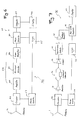
- FIG. 2 shows a block diagram of another radiometer 20 which comprises an antenna 1, a coupler 22, an amplifier 23, a detector 24, a logic circuit 25 and a noise source 27.
- the antenna 1 is operable to receive electromagnetic signals according to the above-mentioned range and sends these signals to the coupler 22.
- the antenna 1 can be a horn antenna.
- the coupler 22 is operable to receive the signal from the antenna 1 and the noise signal from the noise source 27 simultaneously and output a combined signal thereof.
- the coupler 22 can be a directional coupler or a mixer or any other kind of processing device capable to combine the two signals in a specific way. The combination of the signals is performed by for example adding the amplitudes of the two signals.
- the amplifier 23 is operable to receive and amplify the combined signal from the coupler 22 and output an amplified signal thereof.
- the amplification can be manually instructed, predetermined or automatically set based on the received combined signal.
- the detector 24 is operable to receive and process the amplified signal from the amplifier 23, detect the received electromagnetic waves based on the amplified signal and output and display corresponding results and data on a monitor.
- the detector 24 can be a detector diode presenting a specific value which reflects the received intensity of a specific wavelength.
- the detector is preferably a temperature meter which responses to the difference between the first and second level of the received amplified signal.
- the first level is based on the measure antenna signal and the second level is based on the combination of the antenna signal and the noise signal. According to Figure 5 , the first level could base on the combination of antenna signal and antenna noise signal.
- the logic circuit 25 is operable to receive the amplified signal, the data and/or the value from the detector 24 and adjust and output a control signal to the noise source 27 depending on the amplified signal, the data and/or the value of the detector 24.
- the logic circuit 25 is preferably a control circuit which overviews, processes and interacts with all devices of the radiometer.
- the logic circuit 5 preferably ensures that the detector and the switch are synchronized, so that the detector actually measures only a specific signal; either the antenna signal or the combined signal of the antenna signal and the noise signal. In another example, the logic circuit 5 merely indicates to the detector 4 which signal is currently measured.
- the noise source 27 is operable to receive the control signal from the logic circuit 25, generate a noise signal based on the control signal and output the noise signal.
- the control signal can turn the generation of the noise signal of the noise source 27 on and off.
- the noise source 27 can be a noise diode, which is preferably integrated in the coupler 22, whereby the power of the noise diode is controlled by the control signal.
- the noise source 27 can switch between cold and warm noise sources and thus provide a noise source range which corresponds to a temperature range of about 40 to 300K.
- the temperature of the noise source 27 is controlled by the control signal and depends on the temperature measured or to be measured by the antenna 1.
- any other kind of radio receiver like a tuned radio frequency receiver as shown in Figure 6
- a super heterodyne receiver with and without input signal amplifier can be used instead of an amplifier 23 and a detector 24 .
- any Dicke-radiometer can be equipped with said noise source 27 to replace the switch commonly known as Dicke-switch.
- cost reduction can be achieved by reducing the number of components used, resulting in reduction of chip size or reduction of external waveguide components.
- One of the key features of the invention is thus to control the strength of the inserted noise signal in an mm wave imaging system using the noise diode.
- Figure 3 shows a signal diagram describing the two different control signals S1 and S2 generated by the logic circuit 5 or 25 for the switch 6 or for the internal noise signal generator 27.
- Both control signals S1 and S2 are periodic square wave signals comprising the period time lengths T P1 and T P2 , whereby the two periods T P1 and T P2 are favourably equal in length.
- the signals S1 and S2 respectively comprise the upper limit with U1 volts and the lower limit with zero volts, whereby U1 is bigger than zero volts.
- S1 and S2 comprise a plurality of periods like T P1 , respectively.
- the signal S1 comprises within its periods T P1 and T P2 the calibration time T Cal 1,1 and the measurement time T M 1,1 and the calibration time T Cal 1,2 and the measurement time T M 1,2 , respectively.
- the calibration time T Cal 1,1 is equal to the measurement time T M 1,1
- the calibration time T Cal 1,2 is equal to the measurement time T M 1,2 .
- the signal S2 comprises within its periods T P1 and T P2 the calibration time T Cal 2,1 and the measurement time T M 2,1 and the calibration time T Cal 2,2 and the measurement time T M 2,2 , respectively.
- the calibration time T Cal 2,1 is shorter than the measurement time T M 2,1 and the calibration time T Cal 2,2 is shorter than the measurement time T M 2,2 .
- the noise signal is combined with the antenna signal as described in Figure 1 or 2 , while during the measurement time, the noise signal is not combined with antenna signal and only the antenna signal is received and processed in the radiometer.
- the switching is preferably not constant, meaning that the length of the measurement time should be longer than the length of the calibration time. In this way the results are better and more stable and reliable and less time is used for calibration.
- signal S2 is used as control signal than signal S1.
- T P1 and T P2 are not equal, either the calibration time T Cal 1,1 and the calibration time T Cal 1,2 are equally long or the measurement time T M 1,1 and the measurement time T M 1,2 are equally long or none of them is equal to each other. In case T P1 and T P2 are equal in length, the calibration time T Cal 1,1 and the calibration time T Cal 1,2 are equally long and at the same time the measurement time T M 1,1 and the measurement time T M 1,2 are equally long.
- the upper limit U1 and/or the lower limit of one period might be different to the upper limit U1 and/or the lower limit of another period.
- the lower limit is also not restricted to zero volts.
- the signals S1 and S2 can be delta signals or signals with different or equal steep slopes of a saw tooth generator or pulse-width modulated signals.
- Figure 4 shows a gain vs. time diagram describing the drift function of a radiometer.
- the x-axis is the time axis and the y-axis is the gain axis.
- the graph of the drift function is a hyperbole, wherein the left-handed limes goes to positive infinity in the y-direction approaching a line parallel to the y-axis.
- the right-handed limes goes to positive infinity in the x-direction approaching a line parallel to the x-axis.
- the sensitivity of a radiometer like regarding the minimum detectable signal is determined by the amplitude of the fluctuations present at the output indicator in the absence of a signal.
- One source for fluctuations lies within the noise waveform. This fluctuation can be reduced by reducing the post-detection bandwidth or by longer integrating the observed antenna signal.
- Another source of fluctuations which occur at the receiver output is attributable to receiver gain instabilities. This fluctuation can be reduced by reducing the RF input temperature unbalance which is achievable by addition of noise to the signal port of the radiometer as shown in Figure 5 , use of a low temperature comparison source, introduction of gain modulation and furthermore.
- the longer the radiometer measures the antenna signal the less steep the slope of the first derivate will be and the less drift will occur in the radiometer; thus less calibration will be required to reset the radiometer.
- FIG. 5 shows a block diagram of an antenna 1a which comprises an antenna 1 coupled to an internal noise source 51 via a coupler 52.
- the noise signal of the internal noise source 51 is never turned off by a switch or a control signal and is thus continuously combined with the signal of the antenna 1 by the coupler 52.
- the antenna 1 corresponds to the antenna 1 described in Figure 1 and the coupler 52 can correspond to the coupler 2 of Figure 1 or the coupler 22 of Figure 2 .
- the noise source 51 corresponds to the noise source 7 of Figure 1 , whereby the noise signal can be a predetermined signal which is periodically or continuously generated.
- the antenna 1 in the Figures 1 and 2 can be replaced by the antenna 1a. Especially, in case the temperature based on the received antenna signal is calculated in a different way.
- FIG. 6 shows a block diagram of another radiometer 30, wherein the radiometer 30 comprises an antenna 1a, a coupler 62, an amplifier 33, an envelope detector 34, a video amplifier 35, a phase detector 36, an integrator 37, a display 38, a logic circuit 65 and a noise source 67.
- the amplifier 33, the envelope detector 34 and the video amplifier are part of an amplifier apparatus 63 which is similar to the amplifier 3 or 23 shown in Figure 1 and 2 , respectively.
- phase detector 36, the integrator 37 and the display 38 are part of a detector apparatus 64 which is similar to the detector 4 or 24 shown in Figure 1 and 2 , respectively.
- radio receivers which can be used instead of the amplifier apparatus 63 and the detector apparatus 64.
- the antenna 1a corresponds to the antenna 1a of Figure 5
- the coupler 62 corresponds to the coupler 22 of Figure 2
- the logic circuit 65 corresponds to the logic circuit 25 of Figure 2
- the noise source 67 corresponds to the noise source 27 of Figure 2 .
- the amplifier 33 is similar to the amplifier 3 or 23 of Figure 1 and 2 , respectively.
- the envelope detector 34 is an electronic circuit that takes a high-frequency signal as input like the amplified signal, and provides an output which is the outline or "envelope" of the original signal.
- the envelope detector 34 in a simple setup preferably comprises a diode, a capacitor and a resistor.
- the capacitor in the circuit stores up charge on the rising edge, and releases it slowly through the resistor when the signal falls.
- the diode in series ensures current does not flow backward to the input to the circuit.
- the video amplifier 35 deals with video signals, has varying bandwidths depending on the received video signal and eventually amplifies the signal of the envelope detector 34.
- the phase detector 36 is a frequency mixer or analog multiplier circuit that generates a voltage signal which represents the difference in phase between two signal inputs received from the video amplifier 35 and from the logic device 65.
- the integrator 37 integrates the input signals received from the phase detector 36 and outputs the signals to the display 38.
- the display 38 shows the results of the integrator 37, the phase detector 36, the envelope detector 34 and/or just the received electromagnetic signal from the antenna 1a within a diagram. Or the temperature value of the received electromagnetic signal can be shown.
- FIG. 7 shows a block diagram of another radiometer 40, wherein the radiometer 40 comprises an antenna 1, a coupler 72, an amplifier 41, a separately connectable calibrated attenuator 42, a detector 43, a synchronous detector 44, a feedback amplifier 45, a pulse-width modulator 46, a display 47, a logic circuit 75 and a noise source 77.
- the radiometer 40 comprises an antenna 1, a coupler 72, an amplifier 41, a separately connectable calibrated attenuator 42, a detector 43, a synchronous detector 44, a feedback amplifier 45, a pulse-width modulator 46, a display 47, a logic circuit 75 and a noise source 77.
- the antenna 1 and the coupler 72 correspond to the antenna 1 and to the coupler 22 of the above mentioned figures, respectively.
- the logic circuit 75, the noise source 77 and the display 47 are similar to the logic circuit 25, the noise source 27 and the display 38 of the above mentioned figures, respectively.
- the amplifier 41 is operable to amplify the combined signal of the coupler 72 and output the signal to an adjustment device.
- the calibrated attenuator 42 is part of the adjustment device comprising said calibrated attenuator, a wire without resistor parallel to the attenuator 42 and two switches as respective input and output of the adjustment device.
- the two switches either connect simultaneously to the calibrated attenuator 42 or alternatively to the wire; thus a signal either passes through the wire or through the attenuator.
- the attenuator is switched in, the amount of calibrated noise signal is automatically adjusted for a zero detector output by a null-seeking feedback circuit within pulse width modulator 46.
- the attenuated combined signal energy equals the unattenuated noise signal energy, zero-balance occurs.
- the noise source 77 is turned on for example for calibration, the signal passes through the attenuator 42.
- the detector 43 is operable to receive the signal of the adjustment device and output an error signal input to the synchronous detector 44.
- the synchronous detector 44 is operable to output signals to the feedback amplifier, which are later applied as input to the pulse-width modulator 46 to control the width of the pulses thereof.
- the feedback amplifier 45 is operable to amplify the output signal of the synchronous detector 44 and output an amplified feedback signal.
- the pulse-width modulator 46 is operable to receive and process the amplified feedback signal and output pulses as the result thereof to the logic circuit 75 and/or to the display 47.
- the duty cycle of the modulator 46 is proportional to the amount of noise signal energy needed to balance the circuit, thus the modulator derives an average DC voltage.
- the DC output can be used as a relative value in a temperature comparison mode of operation without calibration.
- the display 47 is preferably a temperature display and operable to present the results of the pulse-width modulator 46 in a visual form.
- the logic circuit 75 synchronously operates the switches of the adjustment device, the synchronous detector 44 and the noise source 77. Furthermore, the logic circuit receives the signals of the pulse-width modulator 46 and sends them to the noise source 77.
- the noise source 77 is turned on or off by the logic device 75 depending on whether the received antenna signal should be combined with the noise signal for calibration reasons or not.
- the signal of the pulse-width modulator 46 is capable to set the temperature of the noise source 77 based on the average DC voltage.
Landscapes
- Physics & Mathematics (AREA)
- General Physics & Mathematics (AREA)
- Life Sciences & Earth Sciences (AREA)
- General Life Sciences & Earth Sciences (AREA)
- Geophysics (AREA)
- Electromagnetism (AREA)
- Radiation Pyrometers (AREA)
Abstract
The present invention relates to a radiometer for detecting electromagnetic signals in the microwave and millimetre wave range. The radiometer comprises an antenna operable to receive the electromagnetic signals, an internal noise signal generator operable to receive a control signal and to generate and output a calibration noise signal depending on the control signal, and a coupler operable to couple the received electromagnetic signal with the calibration noise signal and to output a coupled electromagnetic signal. Furthermore, the internal noise signal generator is activated based on the control signal.
Description
- The stabilisation of mm-wave passive imaging systems, also called radiometer, is the focus of this paper and helps to optimize the detection of hidden obstacles under clothes or in a way that they cannot be seen by the eye. Therefore the system is preferably part of security measurements at e.g. airports, bus stations or public buildings.
- The system can also be used for spectroscopic analysis of a substance or for probing in medicine or biology to differ for example between tumours and healthy tissue. Astronomy can be considered as another field of the invention, whereby the surface radiation of the earth, the radiation of space objects like for example stars or meteorites or the cosmic background radiation can be measured.
- The Crookes radiometer is an early-model infrared-radiation and light-detector. A variant type of this is the Nichols radiometer that operates on a different principle, and is more sensitive than the Crookes type. These two models are very early versions of mm-wave radiometers.
- To obtain a high quality mm-wave radiometric picture, a very stable mm-wave imaging system is needed. There are some well known stabilisation methods, developed in 1960's for radio astronomy. One solution is to stabilize the mm-wave imaging system by adding a well known noise-signal, like e.g. a noise insertion radiometer.
- A noise insertion radiometer consists of a Dicke-radiometer wherein a switch switches between a mm-wave antenna signal and an internal noise signal.
- The present invention describes a radiometer for detecting electromagnetic signals in the microwave and millimetre wave range, which comprises an antenna operable to receive the electromagnetic signals, an internal noise signal generator operable to receive a control signal and to generate and output a calibration noise signal depending on the control signal, and a coupler operable to couple the received electromagnetic signal with the calibration noise signal and to output a coupled electromagnetic signal. Thereby the internal noise signal generator is activated based on the control signal.
- Favourably, the radiometer comprises a detector operable to receive and process the coupled electromagnetic signal and to output a temperature value based on the coupled electromagnetic signal.
Favourably, the radiometer comprises a logic circuit operable to receive, process and send data from and to the detector and to send the control signal to the internal noise signal generator.
Favourably, the control signal is a square wave signal.
Favourably, the control signal is a pulse-width modulated signal.
Favourably, the radiometer comprises an antenna noise signal generator operable to generate and output an antenna noise signal which is coupled to the received electromagnetic signal before the calibration noise signal is coupled to the received electromagnetic signal.
Favourably, the control signal comprises a signal level for calibrating the radiometer and a signal level for measuring the received electromagnetic signals, wherein the time length of the signal level for measuring the received electromagnetic signals is longer than the time length of the signal level for calibrating the radiometer. - The present invention also relates to a method for detecting electromagnetic signals in the microwave and millimetre wave range, which comprises the steps of receiving the electromagnetic signals via an antenna, generating a calibration noise signal depending on a control signal, and coupling the electromagnetic signal with the calibration noise signal. Thereby the generation of the calibration noise signal is activated based on the control signal.
- Favourably, the method comprises the step of outputting a coupled electromagnetic signal, after coupling the electromagnetic signal with the calibration noise signal. Favourably, the method comprises the step of receiving and processing the coupled electromagnetic signal by a detector and outputting a temperature value based on the coupled electromagnetic signal.
- Favourably, the method comprises the step of receiving, processing and sending data from and to the detector and sending the control signal to a noise signal generator to control the generation of the calibration noise signal.
Favourably, the control signal is a square wave signal.
Favourably, the control signal is a pulse-width modulated signal.
Favourably, the method comprises the step of generating and outputting an antenna noise signal by an antenna noise signal generator, whereby said antenna noise signal is coupled to the received electromagnetic signal before the calibration noise signal is coupled to the received electromagnetic signal.
Favourably, the control signal comprises a signal level for calibrating the radiometer and a signal level for measuring the received electromagnetic signals, wherein the time length of the signal level for measuring the received electromagnetic signals is longer than the time length of the signal level for calibrating the radiometer. - The object of the present invention is to reduce the costs of a mm-wave imaging system, which is achieved by a reduction of components that cause a reduction of MMIC chip size or a reduction of external waveguide components.
- With the invention, a RF switch for very high frequencies is no longer needed. This reduces the cost of MMIC's by reducing the chip size or by reducing external waveguide components.
- The main advantages of the present invention are that the system costs less due to the reduced components (reduction of chip size or of external components) and that no impedance mismatch occurs due to the removed RF switch.
- The embodiments of the present invention described by the present invention will become clearer in view of the following figures, wherein
-
Fig. 1 shows a block diagram of a radiometer as an example of the present invention, -
Fig. 2 shows a block diagram of another radiometer being an embodiment of the present invention, -
Fig. 3 shows a signal diagram describing the control signal for the internal noise signal generator, -
Fig. 4 shows a gain vs. time diagram describing the drift curve of a radiometer, -
Fig. 5 shows a block diagram of an antenna coupled to an internal noise source, -
Fig. 6 shows a block diagram of another radiometer being a first alternative embodiment of the present invention, and -
Fig. 7 shows a block diagram of another radiometer being a second alternative embodiment of the present invention. - The present invention relates to a novel design in wavelength imaging systems and is working in the range between infrared and microwave radiation; preferably in the Terahertz radiation range of about 3 THz to 300 GHz, thus within a wavelength range of about 100µm to 1000µm. In the following, the system can refer to a microwave or millimeter wave radiometer or a radiometric sensor or just "radiometer".
- A radiometric sensor is a device for the detection and measurement of electromagnetic energy which is noise-like in character, said device preferably comprises an antenna, a receiver and an output indicator. The electromagnetic energy can originate from a natural or an artificial source, which can be either broadband or of the resonant line type in the frequency domain.
- A radiometric sensor is frequently referred to as a temperature measuring device, since the output indicator is calibrated in degrees Kelvin. Higher temperatures might be related to more incident radiation power. Generally, the term "radiometer" denotes an infrared radiation detector, yet it also comprises detectors operating on any electromagnetic wavelength, e.g. spectroradiometer.
-
Figure 1 shows a block diagram of aradiometer 10 which comprises an antenna 1, acoupler 2, anamplifier 3, adetector 4, alogic circuit 5, aswitch 6 and anoise source 7. - The antenna 1 is operable to receive electromagnetic signals according to the above-mentioned range and sends these signals to the
coupler 2. The antenna 1 can be a horn antenna. - The
coupler 2 is operable to receive the signal from the antenna 1 and via theswitch 6 the noise signal from thenoise source 7 and output a combined signal thereof. Thecoupler 2 can be a directional coupler. The combination of the signals is performed by for example adding the amplitudes of the two signals. The combined signal can either consist of the antenna signal or of both the antenna signal and the noise signal. - The
amplifier 3 is operable to receive and amplify the combined signal from thecoupler 2 and output an amplified signal thereof. The amplification can be manually instructed, predetermined or automatically set based on the received combined signal. - The
detector 4 is operable to receive and process the amplified signal from theamplifier 3, detect the received electromagnetic waves based on the amplified signal and output and display corresponding results and data on a monitor. Thedetector 4 can be a detector diode presenting a specific value which reflects the received intensity of a specific wavelength. - The
logic circuit 5 is operable to receive the amplified signal, the data and/or the value from thedetector 4 and adjust and output a control signal to theswitch 6 depending on the amplified signal, the data and/or the value of thedetector 4. Thelogic circuit 5 also ensures that the detector and the switch are synchronized, so that the detector actually measures only a specific signal; either the antenna signal or the combined signal of the antenna signal and the noise signal. In another example, thelogic circuit 5 merely indicates to thedetector 4 which signal is currently measured. - The
switch 6 is operable to receive the control signal and based on the control signal block or let the noise signal from thenoise source 7 pass through to thecoupler 2. Thus, in the "on"-state theswitch 6 connects thenoise source 7 with thecoupler 2 and in the "off"-state theswitch 6 preferably disconnects thenoise source 7 or connects thecoupler 2 with the ground. The switch is preferably a RF switch like a PIN diode. - The
noise source 7 is operable to generate a noise signal and output the noise signal to the switch. Thereby thenoise source 7 continuously generates the noise signal without being switched off during the reception, the processing and/or the measurement of the received electromagnetic signal. - All devices within the
radiometer 10 which are connected to each other as mentioned above are preferably impedance matched, so that no attenuation of the signals due to the reflection occurs. In case attenuation is wanted for example when a signal is too strong, the impedance can be adjusted accordingly. This fact applies to all devices described in the respective figures of the present invention. -
Figure 2 shows a block diagram of anotherradiometer 20 which comprises an antenna 1, acoupler 22, anamplifier 23, a detector 24, alogic circuit 25 and anoise source 27. - The antenna 1 is operable to receive electromagnetic signals according to the above-mentioned range and sends these signals to the
coupler 22. The antenna 1 can be a horn antenna. - The
coupler 22 is operable to receive the signal from the antenna 1 and the noise signal from thenoise source 27 simultaneously and output a combined signal thereof. Thecoupler 22 can be a directional coupler or a mixer or any other kind of processing device capable to combine the two signals in a specific way. The combination of the signals is performed by for example adding the amplitudes of the two signals. - The
amplifier 23 is operable to receive and amplify the combined signal from thecoupler 22 and output an amplified signal thereof. The amplification can be manually instructed, predetermined or automatically set based on the received combined signal. - The detector 24 is operable to receive and process the amplified signal from the
amplifier 23, detect the received electromagnetic waves based on the amplified signal and output and display corresponding results and data on a monitor. The detector 24 can be a detector diode presenting a specific value which reflects the received intensity of a specific wavelength. The detector is preferably a temperature meter which responses to the difference between the first and second level of the received amplified signal. The first level is based on the measure antenna signal and the second level is based on the combination of the antenna signal and the noise signal. According toFigure 5 , the first level could base on the combination of antenna signal and antenna noise signal. - The
logic circuit 25 is operable to receive the amplified signal, the data and/or the value from the detector 24 and adjust and output a control signal to thenoise source 27 depending on the amplified signal, the data and/or the value of the detector 24. Thelogic circuit 25 is preferably a control circuit which overviews, processes and interacts with all devices of the radiometer. Thelogic circuit 5 preferably ensures that the detector and the switch are synchronized, so that the detector actually measures only a specific signal; either the antenna signal or the combined signal of the antenna signal and the noise signal. In another example, thelogic circuit 5 merely indicates to thedetector 4 which signal is currently measured. - The
noise source 27 is operable to receive the control signal from thelogic circuit 25, generate a noise signal based on the control signal and output the noise signal. The control signal can turn the generation of the noise signal of thenoise source 27 on and off. Thenoise source 27 can be a noise diode, which is preferably integrated in thecoupler 22, whereby the power of the noise diode is controlled by the control signal. Preferably, thenoise source 27 can switch between cold and warm noise sources and thus provide a noise source range which corresponds to a temperature range of about 40 to 300K. The temperature of thenoise source 27 is controlled by the control signal and depends on the temperature measured or to be measured by the antenna 1. - Eventually, all devices in
Figure 2 are similar to the devices inFigure 1 , except that the noise diode is directly connected into the signal path of the directional coupler instead of interconnecting an RF switch. The regulation of the inserted noise power by the noise diode is no longer controlled by switching the RF switch on and off. This regulation is done by supplying the noise diode by a square wave signal or a pulse-width modulated signal, supplied by the control logic of the radiometer. - It is emphasized that instead of an
amplifier 23 and a detector 24, any other kind of radio receiver like a tuned radio frequency receiver as shown inFigure 6 , a super heterodyne receiver with and without input signal amplifier can be used. Furthermore, any Dicke-radiometer can be equipped with saidnoise source 27 to replace the switch commonly known as Dicke-switch. - Using this design, cost reduction can be achieved by reducing the number of components used, resulting in reduction of chip size or reduction of external waveguide components.
- One of the key features of the invention is thus to control the strength of the inserted noise signal in an mm wave imaging system using the noise diode.
-
Figure 3 shows a signal diagram describing the two different control signals S1 and S2 generated by thelogic circuit switch 6 or for the internalnoise signal generator 27. - Both control signals S1 and S2 are periodic square wave signals comprising the period time lengths TP1 and TP2, whereby the two periods TP1 and TP2 are favourably equal in length. The signals S1 and S2 respectively comprise the upper limit with U1 volts and the lower limit with zero volts, whereby U1 is bigger than zero volts. Of course, S1 and S2 comprise a plurality of periods like TP1, respectively.
- The signal S1 comprises within its periods TP1 and TP2 the calibration time TCal 1,1 and the measurement time TM 1,1 and the calibration time TCal 1,2 and the measurement time TM 1,2, respectively. In
Figure 3 , the calibration time TCal 1,1 is equal to the measurement time TM 1,1 and the calibration time TCal 1,2 is equal to the measurement time TM 1,2. - The signal S2 comprises within its periods TP1 and TP2 the calibration time TCal 2,1 and the measurement time TM 2,1 and the calibration time TCal 2,2 and the measurement time TM 2,2, respectively. In
Figure 3 , the calibration time TCal 2,1 is shorter than the measurement time TM 2,1 and the calibration time TCal 2,2 is shorter than the measurement time TM 2,2. - During the calibration time, the noise signal is combined with the antenna signal as described in
Figure 1 or 2 , while during the measurement time, the noise signal is not combined with antenna signal and only the antenna signal is received and processed in the radiometer. The switching is preferably not constant, meaning that the length of the measurement time should be longer than the length of the calibration time. In this way the results are better and more stable and reliable and less time is used for calibration. Thus, preferably signal S2 is used as control signal than signal S1. - As soon as the gradient of the drift curve is high, more calibration time is required; in case the gradient of the drift curve is low, less calibration time is required. This description is clearer in view of the gain vs. time diagram in
Figure 4 , wherein the first derivative g(t1) at the time t1 of the drift curve function is steeper than the first derivative g(t2) at the time t2. The steeper the first derivative of the function, the larger the drift and the more calibration time is required. - In case TP1 and TP2 are not equal, either the calibration time TCal 1,1 and the calibration time TCal 1,2 are equally long or the measurement time TM 1,1 and the measurement time TM 1,2 are equally long or none of them is equal to each other. In case TP1 and TP2 are equal in length, the calibration time TCal 1,1 and the calibration time TCal 1,2 are equally long and at the same time the measurement time TM 1,1 and the measurement time TM 1,2 are equally long.
- In another example, also the upper limit U1 and/or the lower limit of one period might be different to the upper limit U1 and/or the lower limit of another period. The lower limit is also not restricted to zero volts.
- In other examples, the signals S1 and S2 can be delta signals or signals with different or equal steep slopes of a saw tooth generator or pulse-width modulated signals.
-
Figure 4 shows a gain vs. time diagram describing the drift function of a radiometer. The x-axis is the time axis and the y-axis is the gain axis. The graph of the drift function is a hyperbole, wherein the left-handed limes goes to positive infinity in the y-direction approaching a line parallel to the y-axis. The right-handed limes goes to positive infinity in the x-direction approaching a line parallel to the x-axis. - The sensitivity of a radiometer like regarding the minimum detectable signal is determined by the amplitude of the fluctuations present at the output indicator in the absence of a signal.
One source for fluctuations lies within the noise waveform. This fluctuation can be reduced by reducing the post-detection bandwidth or by longer integrating the observed antenna signal.
Another source of fluctuations which occur at the receiver output is attributable to receiver gain instabilities. This fluctuation can be reduced by reducing the RF input temperature unbalance which is achievable by addition of noise to the signal port of the radiometer as shown inFigure 5 , use of a low temperature comparison source, introduction of gain modulation and furthermore. - According to the graph, the longer the radiometer measures the antenna signal, the less steep the slope of the first derivate will be and the less drift will occur in the radiometer; thus less calibration will be required to reset the radiometer.
-
Figure 5 shows a block diagram of an antenna 1a which comprises an antenna 1 coupled to aninternal noise source 51 via acoupler 52. - In the shown example, the noise signal of the
internal noise source 51 is never turned off by a switch or a control signal and is thus continuously combined with the signal of the antenna 1 by thecoupler 52. The antenna 1 corresponds to the antenna 1 described inFigure 1 and thecoupler 52 can correspond to thecoupler 2 ofFigure 1 or thecoupler 22 ofFigure 2 . Thenoise source 51 corresponds to thenoise source 7 ofFigure 1 , whereby the noise signal can be a predetermined signal which is periodically or continuously generated. - For specific purposes, the antenna 1 in the
Figures 1 and 2 can be replaced by the antenna 1a. Especially, in case the temperature based on the received antenna signal is calculated in a different way. -
Figure 6 shows a block diagram of anotherradiometer 30, wherein theradiometer 30 comprises an antenna 1a, acoupler 62, anamplifier 33, anenvelope detector 34, avideo amplifier 35, aphase detector 36, anintegrator 37, adisplay 38, alogic circuit 65 and anoise source 67. - The
amplifier 33, theenvelope detector 34 and the video amplifier are part of anamplifier apparatus 63 which is similar to theamplifier Figure 1 and 2 , respectively. - The
phase detector 36, theintegrator 37 and thedisplay 38 are part of adetector apparatus 64 which is similar to thedetector 4 or 24 shown inFigure 1 and 2 , respectively. - As mentioned above, there are different kind of radio receivers which can be used instead of the
amplifier apparatus 63 and thedetector apparatus 64. - The antenna 1a corresponds to the antenna 1a of
Figure 5 , thecoupler 62 corresponds to thecoupler 22 ofFigure 2 , thelogic circuit 65 corresponds to thelogic circuit 25 ofFigure 2 and thenoise source 67 corresponds to thenoise source 27 ofFigure 2 . - The
amplifier 33 is similar to theamplifier Figure 1 and 2 , respectively. - The
envelope detector 34 is an electronic circuit that takes a high-frequency signal as input like the amplified signal, and provides an output which is the outline or "envelope" of the original signal. Theenvelope detector 34 in a simple setup preferably comprises a diode, a capacitor and a resistor. The capacitor in the circuit stores up charge on the rising edge, and releases it slowly through the resistor when the signal falls. The diode in series ensures current does not flow backward to the input to the circuit. - The
video amplifier 35 deals with video signals, has varying bandwidths depending on the received video signal and eventually amplifies the signal of theenvelope detector 34. - The
phase detector 36 is a frequency mixer or analog multiplier circuit that generates a voltage signal which represents the difference in phase between two signal inputs received from thevideo amplifier 35 and from thelogic device 65. - The
integrator 37 integrates the input signals received from thephase detector 36 and outputs the signals to thedisplay 38. - The
display 38 shows the results of theintegrator 37, thephase detector 36, theenvelope detector 34 and/or just the received electromagnetic signal from the antenna 1a within a diagram. Or the temperature value of the received electromagnetic signal can be shown. -
Figure 7 shows a block diagram of anotherradiometer 40, wherein theradiometer 40 comprises an antenna 1, acoupler 72, anamplifier 41, a separately connectable calibratedattenuator 42, adetector 43, asynchronous detector 44, afeedback amplifier 45, a pulse-width modulator 46, adisplay 47, alogic circuit 75 and anoise source 77. - The antenna 1 and the
coupler 72 correspond to the antenna 1 and to thecoupler 22 of the above mentioned figures, respectively. - The
logic circuit 75, thenoise source 77 and thedisplay 47 are similar to thelogic circuit 25, thenoise source 27 and thedisplay 38 of the above mentioned figures, respectively. - The
amplifier 41 is operable to amplify the combined signal of thecoupler 72 and output the signal to an adjustment device. - The calibrated
attenuator 42 is part of the adjustment device comprising said calibrated attenuator, a wire without resistor parallel to theattenuator 42 and two switches as respective input and output of the adjustment device. The two switches either connect simultaneously to the calibratedattenuator 42 or alternatively to the wire; thus a signal either passes through the wire or through the attenuator. When the attenuator is switched in, the amount of calibrated noise signal is automatically adjusted for a zero detector output by a null-seeking feedback circuit withinpulse width modulator 46. When the attenuated combined signal energy equals the unattenuated noise signal energy, zero-balance occurs. Preferably, when thenoise source 77 is turned on for example for calibration, the signal passes through theattenuator 42. - The
detector 43 is operable to receive the signal of the adjustment device and output an error signal input to thesynchronous detector 44. - The
synchronous detector 44 is operable to output signals to the feedback amplifier, which are later applied as input to the pulse-width modulator 46 to control the width of the pulses thereof. - The
feedback amplifier 45 is operable to amplify the output signal of thesynchronous detector 44 and output an amplified feedback signal. - The pulse-
width modulator 46 is operable to receive and process the amplified feedback signal and output pulses as the result thereof to thelogic circuit 75 and/or to thedisplay 47. The duty cycle of themodulator 46 is proportional to the amount of noise signal energy needed to balance the circuit, thus the modulator derives an average DC voltage. The DC output can be used as a relative value in a temperature comparison mode of operation without calibration. - The
display 47 is preferably a temperature display and operable to present the results of the pulse-width modulator 46 in a visual form. - The
logic circuit 75 synchronously operates the switches of the adjustment device, thesynchronous detector 44 and thenoise source 77. Furthermore, the logic circuit receives the signals of the pulse-width modulator 46 and sends them to thenoise source 77. - The
noise source 77 is turned on or off by thelogic device 75 depending on whether the received antenna signal should be combined with the noise signal for calibration reasons or not. The signal of the pulse-width modulator 46 is capable to set the temperature of thenoise source 77 based on the average DC voltage.
Claims (15)
- A radiometer (20) for detecting electromagnetic signals in the microwave and millimetre wave range
comprising
an antenna (1) operable to receive the electromagnetic signals,
an internal noise signal generator (27) operable to receive a control signal and to generate and output a calibration noise signal depending on the control signal, and
a coupler (22) operable to couple the received electromagnetic signal with the calibration noise signal and to output a coupled electromagnetic signal,
whereby the internal noise signal generator (27) is activated based on the control signal. - A radiometer according to claim 1,
comprising a detector (24) operable to receive and process the coupled electromagnetic signal and to output a temperature value based on the coupled electromagnetic signal. - A radiometer according to claim 2,
comprising a logic circuit (25) operable to receive, process and send data from and to the detector (24) and to send the control signal to the internal noise signal generator (27). - A radiometer according to one of the above-mentioned claims,
wherein the control signal is a square wave signal. - A radiometer according to one of the claims 1 to 3,
wherein the control signal is a pulse-width modulated signal. - A radiometer according to one of the above-mentioned claims,
comprising an antenne noise signal generator (51) operable to generate and output an antenna noise signal which is coupled to the received electromagnetic signal before the calibration noise signal is coupled to the received electromagnetic signal. - A radiometer according to one of the above-mentioned claims,
wherein the control signal comprises a signal level for calibrating the radiometer (20) and a signal level for measuring the received electromagnetic signals,
wherein the time length of the signal level for measuring the received electromagnetic signals is longer than the time length of the signal level for calibrating the radiometer. - A method for detecting electromagnetic signals in the microwave and millimetre wave range,
comprising the steps of
receiving the electromagnetic signals via an antenna (1),
generating a calibration noise signal depending on a control signal, and
coupling the electromagnetic signal with the calibration noise signal,
whereby the generation of the calibration noise signal is activated based on the control signal. - A method according to claim 8,
comprising the step of
outputting a coupled electromagnetic signal, after coupling the electromagnetic signal with the calibration noise signal. - A method according to claim 9,
comprising the step of
receiving and processing the coupled electromagnetic signal by a detector (24) and
outputting a temperature value based on the coupled electromagnetic signal. - A method according to claim 10,
comprising the step of
receiving, processing and sending data from and to the detector and
sending the control signal to a noise signal generator to control the generation of the calibration noise signal. - A method according to one of the claims 8 to 11,
wherein the control signal is a square wave signal. - A method according to one of the claims 8 to 11,
wherein the control signal is a pulse-width modulated signal. - A method according to one of the claims 8 to 13,
comprising the step of
generating and outputting an antenna noise signal by an antenna noise signal generator, whereby said antenna noise signal is coupled to the received electromagnetic signal before the calibration noise signal is coupled to the received electromagnetic signal. - A method according to one of the claims 8 to 14,
wherein the control signal comprises a signal level for calibrating the radiometer and a signal level for measuring the received electromagnetic signals,
wherein the time length of the signal level for measuring the received electromagnetic signals is longer than the time length of the signal level for calibrating the radiometer.
Priority Applications (3)
| Application Number | Priority Date | Filing Date | Title |
|---|---|---|---|
| EP09150983A EP2211155A1 (en) | 2009-01-21 | 2009-01-21 | Method and system to measure noise inserted mm-waves |
| US12/631,090 US8227746B2 (en) | 2009-01-21 | 2009-12-04 | Method and system to measure noise inserted mm-waves |
| CN201010004486.8A CN101782610B (en) | 2009-01-21 | 2010-01-21 | Method and system to measure noise inserted mm-waves |
Applications Claiming Priority (1)
| Application Number | Priority Date | Filing Date | Title |
|---|---|---|---|
| EP09150983A EP2211155A1 (en) | 2009-01-21 | 2009-01-21 | Method and system to measure noise inserted mm-waves |
Publications (1)
| Publication Number | Publication Date |
|---|---|
| EP2211155A1 true EP2211155A1 (en) | 2010-07-28 |
Family
ID=40801869
Family Applications (1)
| Application Number | Title | Priority Date | Filing Date |
|---|---|---|---|
| EP09150983A Withdrawn EP2211155A1 (en) | 2009-01-21 | 2009-01-21 | Method and system to measure noise inserted mm-waves |
Country Status (3)
| Country | Link |
|---|---|
| US (1) | US8227746B2 (en) |
| EP (1) | EP2211155A1 (en) |
| CN (1) | CN101782610B (en) |
Cited By (1)
| Publication number | Priority date | Publication date | Assignee | Title |
|---|---|---|---|---|
| CN109668910A (en) * | 2018-12-26 | 2019-04-23 | 南京理工大学 | Material radiance test method and device based on millimeter wave |
Families Citing this family (9)
| Publication number | Priority date | Publication date | Assignee | Title |
|---|---|---|---|---|
| CN102135610B (en) * | 2010-12-28 | 2013-03-06 | 中国航天科工集团第二研究院二○三所 | Near-field real-time calibration method for human body millimeter wave imaging safety inspection system |
| CN102495435B (en) * | 2011-11-15 | 2013-10-09 | 北京无线电计量测试研究所 | Calibration method for multichannel transmission delay of body security inspection system |
| CN103529421B (en) * | 2013-10-29 | 2015-11-04 | 北京无线电计量测试研究所 | A kind of coupling mechanism calibration steps |
| US10042083B2 (en) * | 2014-07-16 | 2018-08-07 | Elwha Llc | Systems and methods for microwave sensing of object properties |
| CN104931816B (en) * | 2015-05-31 | 2018-01-05 | 南京理工大学 | The Millimeter Wave Radiometric Characteristic measurement apparatus and measuring method of a kind of fabric |
| CN106533412A (en) * | 2016-10-20 | 2017-03-22 | 华中科技大学 | Low-loss active switch for receiver |
| TWI639840B (en) * | 2017-04-07 | 2018-11-01 | 莊晴光 | Electromagnetic signal detecting circuit and corresponiding detecting method |
| JP7455611B2 (en) * | 2019-03-14 | 2024-03-26 | キヤノン株式会社 | processing system |
| US11092693B2 (en) * | 2019-07-23 | 2021-08-17 | Rockwell Collins, Inc. | Automatic external RF gain calibration and continuous jamming measurement |
Citations (3)
| Publication number | Priority date | Publication date | Assignee | Title |
|---|---|---|---|---|
| US5438336A (en) * | 1993-11-12 | 1995-08-01 | Trw Inc. | Focal plane imaging array with internal calibration source |
| US5949845A (en) * | 1995-04-03 | 1999-09-07 | Mmtc, Inc. | Temperature-measuring microwave radiometer apparatus |
| US20050053118A1 (en) * | 2003-07-11 | 2005-03-10 | University Of Texas System | Remote temperature measuring system for hostile industrial environments using microwave radiometry |
Family Cites Families (9)
| Publication number | Priority date | Publication date | Assignee | Title |
|---|---|---|---|---|
| US3599207A (en) * | 1969-10-16 | 1971-08-10 | Donald L Foian | Combined frequency modulated radar and radiometer |
| US3653045A (en) * | 1970-06-03 | 1972-03-28 | Sperry Rand Corp | Radiometer modulator-demodulator system |
| US4292638A (en) * | 1971-06-17 | 1981-09-29 | Sperry Corporation | Augmented radiometric system |
| US3777270A (en) * | 1972-05-12 | 1973-12-04 | Rockwell International Corp | Precision variable pulse rate nulling radiometer |
| DE2803480C2 (en) * | 1978-01-27 | 1984-11-22 | Philips Patentverwaltung Gmbh, 2000 Hamburg | Method and arrangement for measuring the physical object temperature by means of microwaves |
| US4488559A (en) * | 1981-06-30 | 1984-12-18 | University Of Utah | Apparatus and method for measuring lung water content |
| US5815113A (en) * | 1996-08-13 | 1998-09-29 | Trw Inc. | Monolithic, low-noise, synchronous direct detection receiver for passive microwave/millimeter-wave radiometric imaging systems |
| US7088086B2 (en) * | 2003-09-18 | 2006-08-08 | Xytrans, Inc. | Multi-channel radiometer imaging system |
| US7221141B2 (en) * | 2004-07-14 | 2007-05-22 | Xytrans, Inc. | Switched measuring system and method for measuring radiant signals |
-
2009
- 2009-01-21 EP EP09150983A patent/EP2211155A1/en not_active Withdrawn
- 2009-12-04 US US12/631,090 patent/US8227746B2/en not_active Expired - Fee Related
-
2010
- 2010-01-21 CN CN201010004486.8A patent/CN101782610B/en not_active Expired - Fee Related
Patent Citations (3)
| Publication number | Priority date | Publication date | Assignee | Title |
|---|---|---|---|---|
| US5438336A (en) * | 1993-11-12 | 1995-08-01 | Trw Inc. | Focal plane imaging array with internal calibration source |
| US5949845A (en) * | 1995-04-03 | 1999-09-07 | Mmtc, Inc. | Temperature-measuring microwave radiometer apparatus |
| US20050053118A1 (en) * | 2003-07-11 | 2005-03-10 | University Of Texas System | Remote temperature measuring system for hostile industrial environments using microwave radiometry |
Cited By (1)
| Publication number | Priority date | Publication date | Assignee | Title |
|---|---|---|---|---|
| CN109668910A (en) * | 2018-12-26 | 2019-04-23 | 南京理工大学 | Material radiance test method and device based on millimeter wave |
Also Published As
| Publication number | Publication date |
|---|---|
| CN101782610B (en) | 2013-01-02 |
| US8227746B2 (en) | 2012-07-24 |
| US20100194625A1 (en) | 2010-08-05 |
| CN101782610A (en) | 2010-07-21 |
Similar Documents
| Publication | Publication Date | Title |
|---|---|---|
| US8227746B2 (en) | Method and system to measure noise inserted mm-waves | |
| US7052176B2 (en) | Remote temperature measuring system for hostile industrial environments using microwave radiometry | |
| US6834991B2 (en) | Radiometer with programmable noise source calibration | |
| US10094914B2 (en) | Method and system for propagation time measurement and calibration using mutual coupling in a radio frequency transmit/receive system | |
| CN106291740B (en) | Power regulating method, device and human body safety check equipment | |
| US7121719B2 (en) | Radio-thermometer system and method for measuring electromagnetic energy radiated from an interior of a human body using the same | |
| KR102549408B1 (en) | Pulse radar apparatus and operating method thereof | |
| US20100014079A1 (en) | Optical measuring apparatus | |
| EP2980553A1 (en) | Structural health monitoring sensor system and method using resonant transmission line sensors | |
| Gogoi et al. | A compact multi-mode integrated Doppler radar at 2.4 ghz for multipurpose applications | |
| KR100557429B1 (en) | Electromagnetic wave generator for verification of electromagnetic wave absorption rate measuring device | |
| RU2082985C1 (en) | Gear measuring directivity diagrams of antenna in far zone | |
| KR20050008335A (en) | Apparatus having a function of radar and radiometer | |
| JP2000241535A (en) | Short-distance radar device | |
| Beatty | The system of electromagnetic quantities at frequencies above 1 GHz | |
| Marimuthu et al. | Low cost microwave imaging system using eight element switched antenna array | |
| Ali et al. | A measurement setup for THz detectors characterization validated on FET-based CMOS test structures | |
| JPH05253239A (en) | Heating unit | |
| Korneev et al. | The latest developments of microwave diagnostics for high temperature plasma in ELVA-1 company | |
| RU2108594C1 (en) | Device measuring amplitude-frequency characteristics of target | |
| Azaro et al. | Electromagnetic field uniformity test using modulated scattering probes | |
| Legg | Microwave phase comparators for large antenna arrays | |
| Kazemipour et al. | THz Detector Calibration Based on Microwave Power Standards | |
| Kriz | A Novel Approach for a Reference Radiator in Frequency Range above 1 GHz | |
| CN121831667A (en) | Radar beacon equipment with power measurement feedback adjustment and power measurement feedback adjustment method |
Legal Events
| Date | Code | Title | Description |
|---|---|---|---|
| PUAI | Public reference made under article 153(3) epc to a published international application that has entered the european phase |
Free format text: ORIGINAL CODE: 0009012 |
|
| AK | Designated contracting states |
Kind code of ref document: A1 Designated state(s): AT BE BG CH CY CZ DE DK EE ES FI FR GB GR HR HU IE IS IT LI LT LU LV MC MK MT NL NO PL PT RO SE SI SK TR |
|
| AX | Request for extension of the european patent |
Extension state: AL BA RS |
|
| AKY | No designation fees paid | ||
| STAA | Information on the status of an ep patent application or granted ep patent |
Free format text: STATUS: THE APPLICATION IS DEEMED TO BE WITHDRAWN |
|
| 18D | Application deemed to be withdrawn |
Effective date: 20110129 |