EP2211107A2 - Insertable Pre-Drilled Swirl Vane for Premixing Fuel Nozzle - Google Patents
Insertable Pre-Drilled Swirl Vane for Premixing Fuel Nozzle Download PDFInfo
- Publication number
- EP2211107A2 EP2211107A2 EP10151143A EP10151143A EP2211107A2 EP 2211107 A2 EP2211107 A2 EP 2211107A2 EP 10151143 A EP10151143 A EP 10151143A EP 10151143 A EP10151143 A EP 10151143A EP 2211107 A2 EP2211107 A2 EP 2211107A2
- Authority
- EP
- European Patent Office
- Prior art keywords
- fuel
- structural body
- swirl
- central hub
- fuel nozzle
- Prior art date
- Legal status (The legal status is an assumption and is not a legal conclusion. Google has not performed a legal analysis and makes no representation as to the accuracy of the status listed.)
- Withdrawn
Links
- 239000000446 fuel Substances 0.000 title claims abstract description 82
- 238000000034 method Methods 0.000 claims description 13
- 238000012360 testing method Methods 0.000 claims description 7
- 238000005266 casting Methods 0.000 claims description 5
- 238000005553 drilling Methods 0.000 claims description 3
- 238000003754 machining Methods 0.000 claims 2
- 238000005219 brazing Methods 0.000 claims 1
- 238000003466 welding Methods 0.000 claims 1
- 239000007789 gas Substances 0.000 description 29
- VNWKTOKETHGBQD-UHFFFAOYSA-N methane Chemical compound C VNWKTOKETHGBQD-UHFFFAOYSA-N 0.000 description 14
- 238000002485 combustion reaction Methods 0.000 description 12
- 239000003345 natural gas Substances 0.000 description 7
- 238000006243 chemical reaction Methods 0.000 description 6
- 239000000203 mixture Substances 0.000 description 6
- IJGRMHOSHXDMSA-UHFFFAOYSA-N Atomic nitrogen Chemical compound N#N IJGRMHOSHXDMSA-UHFFFAOYSA-N 0.000 description 5
- 238000002347 injection Methods 0.000 description 4
- 239000007924 injection Substances 0.000 description 4
- 238000007514 turning Methods 0.000 description 4
- 238000004458 analytical method Methods 0.000 description 3
- 238000009826 distribution Methods 0.000 description 3
- 239000011888 foil Substances 0.000 description 3
- 229930195733 hydrocarbon Natural products 0.000 description 2
- 150000002430 hydrocarbons Chemical class 0.000 description 2
- 238000009434 installation Methods 0.000 description 2
- 238000004519 manufacturing process Methods 0.000 description 2
- 229910052757 nitrogen Inorganic materials 0.000 description 2
- 239000004215 Carbon black (E152) Substances 0.000 description 1
- UGFAIRIUMAVXCW-UHFFFAOYSA-N Carbon monoxide Chemical compound [O+]#[C-] UGFAIRIUMAVXCW-UHFFFAOYSA-N 0.000 description 1
- 230000015572 biosynthetic process Effects 0.000 description 1
- 229910002091 carbon monoxide Inorganic materials 0.000 description 1
- 238000010276 construction Methods 0.000 description 1
- 230000001419 dependent effect Effects 0.000 description 1
- 238000009792 diffusion process Methods 0.000 description 1
- 238000009760 electrical discharge machining Methods 0.000 description 1
- 230000005484 gravity Effects 0.000 description 1
- 230000013011 mating Effects 0.000 description 1
- 230000003647 oxidation Effects 0.000 description 1
- 238000007254 oxidation reaction Methods 0.000 description 1
- 230000029058 respiratory gaseous exchange Effects 0.000 description 1
Images


Classifications
-
- F—MECHANICAL ENGINEERING; LIGHTING; HEATING; WEAPONS; BLASTING
- F23—COMBUSTION APPARATUS; COMBUSTION PROCESSES
- F23R—GENERATING COMBUSTION PRODUCTS OF HIGH PRESSURE OR HIGH VELOCITY, e.g. GAS-TURBINE COMBUSTION CHAMBERS
- F23R3/00—Continuous combustion chambers using liquid or gaseous fuel
- F23R3/02—Continuous combustion chambers using liquid or gaseous fuel characterised by the air-flow or gas-flow configuration
- F23R3/04—Air inlet arrangements
- F23R3/10—Air inlet arrangements for primary air
- F23R3/12—Air inlet arrangements for primary air inducing a vortex
- F23R3/14—Air inlet arrangements for primary air inducing a vortex by using swirl vanes
-
- F—MECHANICAL ENGINEERING; LIGHTING; HEATING; WEAPONS; BLASTING
- F23—COMBUSTION APPARATUS; COMBUSTION PROCESSES
- F23R—GENERATING COMBUSTION PRODUCTS OF HIGH PRESSURE OR HIGH VELOCITY, e.g. GAS-TURBINE COMBUSTION CHAMBERS
- F23R3/00—Continuous combustion chambers using liquid or gaseous fuel
- F23R3/28—Continuous combustion chambers using liquid or gaseous fuel characterised by the fuel supply
- F23R3/286—Continuous combustion chambers using liquid or gaseous fuel characterised by the fuel supply having fuel-air premixing devices
-
- F—MECHANICAL ENGINEERING; LIGHTING; HEATING; WEAPONS; BLASTING
- F23—COMBUSTION APPARATUS; COMBUSTION PROCESSES
- F23C—METHODS OR APPARATUS FOR COMBUSTION USING FLUID FUEL OR SOLID FUEL SUSPENDED IN A CARRIER GAS OR AIR
- F23C2900/00—Special features of, or arrangements for combustion apparatus using fluid fuels or solid fuels suspended in air; Combustion processes therefor
- F23C2900/07001—Air swirling vanes incorporating fuel injectors
-
- Y—GENERAL TAGGING OF NEW TECHNOLOGICAL DEVELOPMENTS; GENERAL TAGGING OF CROSS-SECTIONAL TECHNOLOGIES SPANNING OVER SEVERAL SECTIONS OF THE IPC; TECHNICAL SUBJECTS COVERED BY FORMER USPC CROSS-REFERENCE ART COLLECTIONS [XRACs] AND DIGESTS
- Y10—TECHNICAL SUBJECTS COVERED BY FORMER USPC
- Y10T—TECHNICAL SUBJECTS COVERED BY FORMER US CLASSIFICATION
- Y10T29/00—Metal working
- Y10T29/49—Method of mechanical manufacture
- Y10T29/49316—Impeller making
- Y10T29/4932—Turbomachine making
- Y10T29/49323—Assembling fluid flow directing devices, e.g., stators, diaphragms, nozzles
Definitions
- the invention relates to a fuel nozzle in a gas turbine including a fuel/air premixer and, more particularly, to a fuel nozzle including independently insertable pre-drilled swirl vanes.
- Typical industrial gas turbine premixing fuel nozzles may employ a cast swirl vane assembly in which a circular array of shaped hollow vanes are used to swirl the incoming air.
- the hollow vanes also serve as fuel delivery passages, where each vane is provided with several gas port holes drilled into the sides, through which fuel is injected into the passing air stream.
- the primary air polluting emissions usually produced by gas turbines burning conventional hydrocarbon fuels are oxides of nitrogen, carbon monoxide, and unburned hydrocarbons. It is well known that oxidation of molecular nitrogen in air breathing engines is highly dependent upon the maximum hot gas temperature in the combustion system reaction zone. The rate of chemical reactions forming oxides of nitrogen (NOx) is an exponential function of temperature. If the temperature of the combustion chamber hot gas is controlled to a sufficiently low level, thermal NOx will not be produced.
- An existing method of controlling the temperature of the reaction zone of a heat engine combustor below the level at which thermal NOx is formed is to premix fuel and air to a lean mixture prior to combustion.
- the thermal mass of the excess air present in the reaction zone of a lean premixed combustor reduces the peak temperatures in the reaction zone to minimize formation of thermal NOx.
- FIG. 1 illustrates a swozzle-type swirl vane assembly, which is described in U.S. Patent No. 6,438,961 .
- a premixing fuel nozzle is divided into four regions by function including an inlet flow conditioner, an air swirler assembly with natural gas fuel injection, an annular fuel air mixing passage, and a central diffusion flame natural gas fuel nozzle assembly.
- the function of the inlet flow conditioner is to prepare the air flow velocity distribution for entry into the premixer. After combustion air exits the inlet flow conditioner, it enters the swozzle assembly 2.
- the swozzle assembly includes a hub 201 and a shroud 202 connected by a series of air foil shaped turning vanes 23, which impart swirl to the combustion air passing through the premixer.
- Each turning vane 23 contains a primary natural gas fuel supply passage 21 and may also contain a secondary natural gas fuel supply passage 22 through the core of the air foil. These fuel passages distribute natural gas fuel to primary gas fuel injection holes and optionally to the secondary gas fuel injection holes that penetrate the wall of the air foil. The fuel injection holes may be located on the pressure side, the suction side or both sides of the turning vanes 23.
- Natural gas fuel enters the swozzle assembly 2 through inlet ports and annular passages that feed the primary and optionally the secondary turning vane passages, respectively. The natural gas fuel begins mixing with combustion air in the swozzle assembly 2, and fuel/air mixing is completed in the annular passage, which is formed by a swozzle hub extension and a swozzle shroud extension. After exiting the annular passage, the fuel/air mixture enters the combustor reaction zone where combustion takes place.
- Flow testing is used to measure the effective opening area of the gas port orifices in the current configuration, and the flow testing is performed after these orifices have been drilled. If the gas port open area is too large, there is no process for repairing or modifying the part to correct this area, and an expensive part must thus be discarded. Additionally, current flow tests can assess the fuel circuit areas for the entire fuel nozzle, but cannot assess the vane-to-vane variation in fuel flow. Since NOx emissions are strongly influenced by local regions of high fuel-air ratio, it is desirable to provide as uniform a fuel-air mixture as possible.
- Fuel nozzle gas port diameters are sized to accommodate a specific range of fuel compositions and temperatures. Changes in operating fuel temperature or fuel specific gravity can require a change in gas port orifice size to maintain proper operation of the gas turbine. As noted, however, such changes are not easily or inexpensively effected.
- Current fuel nozzle designs employ uniform gas port diameters and locations in all swirl vanes. As combustion system analysis methods and system performance continue to evolve, benefits may be accrued from the use of varying gas port locations and/or diameters within a single fuel nozzle. With the prior design, it is not possible to vary the gas port locations and/or diameters without substantial nozzle reconstruction.
- a swirl vane is independently connectable to a central hub assembly of a gas turbine.
- the swirl vane includes a structural body, at least one fuel delivery passage including a corresponding at least one fuel port defined within the structural body, and at least one connecting tab cooperable with the structural body and connectable to the central hub assembly.
- a premixing fuel nozzle for a gas turbine includes a central hub assembly and a plurality of the independently connectable swirl vanes connected to the central hub assembly in a circular array.
- a method of assembling a premixing fuel nozzle for a gas turbine includes the steps of (a) preparing a plurality of swirl vanes to each include a structural body, at least one fuel delivery passage including a corresponding at least one fuel port defined within the structural body, and at least one connecting tab cooperable with the structural body; and (b) securing the plurality of swirl vanes independently to a central hub assembly of the premixing fuel nozzle.
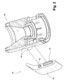
- FIGS. 2 and 3 depict a partial assembly drawing showing a central hub assembly 32 of a gas turbine and an independently connectable swirl vane 34. Although only a single exemplary vane is shown, it is representative of a plurality of vanes.
- the exemplary swirl vane 34 includes a generally hollow structural body 36 including at least one fuel delivery passage 38 and a corresponding at least one fuel port 40 defined within the structural body 36.
- the gas ports 40 can be circular or non-circular and can be formed using drilling, electrical discharge machining (EDM), or any other known process.
- the gas ports can be formed on either the suction or pressure side of the vane, or both sides, and may be normal or canted relative to the surface of the vane.
- the structural body 36 includes a plurality of fuel delivery passages 38 and corresponding fuel ports 40.
- At least one connecting tab 42 is cooperable with the structural body 36 and is connectable to corresponding slots 44 in the central hub assembly 32.
- the independently connectable swirl vane 34 has its fuel passages and ports 38, 40 drilled or machined prior to installation into the central hub assembly 32. By preforming fuel passages and ports 38, 40 prior to installation, each swirl vane 34 can be flow-tested individually to ensure that the fuel circuit effective flow area meets design intent. That is, flow-testing can be used to tune the individual vanes 34 for assurance of proper flow characteristics.
- the independently connectable swirl vanes 34 are then inserted into the central hub assembly 32 and brazed, swaged, welded or connected using any other known process into position via connecting tabs 42 and corresponding slots 44. With individually flow-tested vanes 34, the completed vane assembly would necessarily automatically meet design intent.
- vanes 34 are individually flow-tested, rather than testing the entire assembly as a unit, vane-to-vane variation can be directly measured and easier to control. Moreover, insertable swirl vanes 34 provide a relatively easy way to re-size fuel nozzles for changes in fuel composition. In an exemplary application, the vanes 34 can be machined off the central hub assembly 32 and replaced with re-sized swirl vanes, rather than replacing an entire fuel nozzle.
- the vanes 34 can be cast or machined in both a clockwise and counterclockwise rotational orientation to permit the easy use of counter-rotating swirl. Casting tooling for an individual vane is much less expensive and requires less manufacturing time. Still further, the insertable swirl vanes 34 facilitate the testing of alternate concepts since the vanes can be made more quickly and at a lower cost.
- a clocking feature can be incorporated into the fuel nozzle base, so that the fuel nozzle can only be installed in one orientation relative to the combustor liner; this feature would insure that the position of each swirl vane was fixed, relative to the combustion flow field inside the liner.
- the swirler assembly shroud may be a sepaate entity reather than an integral part of the swirler assembly.
- the insertable swirl vanes 34 can serve to deliver fuel in a non-symmetric, preferentially-oriented manner by incorporating features in the fuel nozzle design that position the fuel nozzle in a unique orientation with respect to the combustor.
- Analysis of the combustor internal flow field may indicate fuel-rich or fuel-lean regions that can be made more uniform by fitting swirl vanes with larger or smaller ports in some sections of the premixing assembly. Because the flow areas of each swirl vane are known prior to assembly, the fuel-air distribution inside the premixing assembly can be tuned to deliver a richer or leaner mixture into different regions of the combustor.
- the independent vanes provide for greater design flexibility. Gas port holes can be drilled into individual vanes much more easily than in a single vane casting since access to the side of the vanes is unimpeded. Moreover, since tooling for drilling the holes is much less complex, there is greater flexibility to use varying gas port configurations among the different vanes in the assembly. This variation offers potential advantages in combustion system operability and emissions, which could yield gas turbine performance improvements.
Landscapes
- Engineering & Computer Science (AREA)
- Chemical & Material Sciences (AREA)
- Combustion & Propulsion (AREA)
- Mechanical Engineering (AREA)
- General Engineering & Computer Science (AREA)
- Turbine Rotor Nozzle Sealing (AREA)
Abstract
Description
- The invention relates to a fuel nozzle in a gas turbine including a fuel/air premixer and, more particularly, to a fuel nozzle including independently insertable pre-drilled swirl vanes.
- Typical industrial gas turbine premixing fuel nozzles may employ a cast swirl vane assembly in which a circular array of shaped hollow vanes are used to swirl the incoming air. The hollow vanes also serve as fuel delivery passages, where each vane is provided with several gas port holes drilled into the sides, through which fuel is injected into the passing air stream.
- Gas turbine manufacturers are currently involved in research and engineering programs to produce new gas turbines that will operate at high efficiency without producing undesirable air polluting emissions. The primary air polluting emissions usually produced by gas turbines burning conventional hydrocarbon fuels are oxides of nitrogen, carbon monoxide, and unburned hydrocarbons. It is well known that oxidation of molecular nitrogen in air breathing engines is highly dependent upon the maximum hot gas temperature in the combustion system reaction zone. The rate of chemical reactions forming oxides of nitrogen (NOx) is an exponential function of temperature. If the temperature of the combustion chamber hot gas is controlled to a sufficiently low level, thermal NOx will not be produced. An existing method of controlling the temperature of the reaction zone of a heat engine combustor below the level at which thermal NOx is formed is to premix fuel and air to a lean mixture prior to combustion. The thermal mass of the excess air present in the reaction zone of a lean premixed combustor reduces the peak temperatures in the reaction zone to minimize formation of thermal NOx.
-
FIG. 1 illustrates a swozzle-type swirl vane assembly, which is described inU.S. Patent No. 6,438,961 . A premixing fuel nozzle is divided into four regions by function including an inlet flow conditioner, an air swirler assembly with natural gas fuel injection, an annular fuel air mixing passage, and a central diffusion flame natural gas fuel nozzle assembly. The function of the inlet flow conditioner is to prepare the air flow velocity distribution for entry into the premixer. After combustion air exits the inlet flow conditioner, it enters theswozzle assembly 2. The swozzle assembly includes ahub 201 and ashroud 202 connected by a series of air foil shapedturning vanes 23, which impart swirl to the combustion air passing through the premixer. Eachturning vane 23 contains a primary natural gasfuel supply passage 21 and may also contain a secondary natural gasfuel supply passage 22 through the core of the air foil. These fuel passages distribute natural gas fuel to primary gas fuel injection holes and optionally to the secondary gas fuel injection holes that penetrate the wall of the air foil. The fuel injection holes may be located on the pressure side, the suction side or both sides of theturning vanes 23. Natural gas fuel enters theswozzle assembly 2 through inlet ports and annular passages that feed the primary and optionally the secondary turning vane passages, respectively. The natural gas fuel begins mixing with combustion air in theswozzle assembly 2, and fuel/air mixing is completed in the annular passage, which is formed by a swozzle hub extension and a swozzle shroud extension. After exiting the annular passage, the fuel/air mixture enters the combustor reaction zone where combustion takes place. - There are numerous problems associated with the existing design. Flow testing is used to measure the effective opening area of the gas port orifices in the current configuration, and the flow testing is performed after these orifices have been drilled. If the gas port open area is too large, there is no process for repairing or modifying the part to correct this area, and an expensive part must thus be discarded. Additionally, current flow tests can assess the fuel circuit areas for the entire fuel nozzle, but cannot assess the vane-to-vane variation in fuel flow. Since NOx emissions are strongly influenced by local regions of high fuel-air ratio, it is desirable to provide as uniform a fuel-air mixture as possible.
- Fuel nozzle gas port diameters are sized to accommodate a specific range of fuel compositions and temperatures. Changes in operating fuel temperature or fuel specific gravity can require a change in gas port orifice size to maintain proper operation of the gas turbine. As noted, however, such changes are not easily or inexpensively effected. Current fuel nozzle designs employ uniform gas port diameters and locations in all swirl vanes. As combustion system analysis methods and system performance continue to evolve, benefits may be accrued from the use of varying gas port locations and/or diameters within a single fuel nozzle. With the prior design, it is not possible to vary the gas port locations and/or diameters without substantial nozzle reconstruction.
- Flow field analysis has shown that the use of counter-rotating swirl in adjacent fuel nozzles can provide operational and/or performance benefits in the combustion system. The complexity of the prior fuel nozzle swirlers casting, however, requires expensive tooling, and thereby makes it very difficult to employ counter-rotating vane configurations.
- Still further, prototype fuel nozzles in the prior design are costly and time-consuming to fabricate. In the prior design, the swirl vanes are integral to the swirl vane casting, which greatly limits the ability to modify prototype hardware for optimal fuel delivery and mixing.
- It would be desirable to provide a design that addresses these drawbacks in the prior construction.
- In an exemplary embodiment, a swirl vane is independently connectable to a central hub assembly of a gas turbine. The swirl vane includes a structural body, at least one fuel delivery passage including a corresponding at least one fuel port defined within the structural body, and at least one connecting tab cooperable with the structural body and connectable to the central hub assembly.
- In another exemplary embodiment, a premixing fuel nozzle for a gas turbine includes a central hub assembly and a plurality of the independently connectable swirl vanes connected to the central hub assembly in a circular array.
- In yet another exemplary embodiment, a method of assembling a premixing fuel nozzle for a gas turbine includes the steps of (a) preparing a plurality of swirl vanes to each include a structural body, at least one fuel delivery passage including a corresponding at least one fuel port defined within the structural body, and at least one connecting tab cooperable with the structural body; and (b) securing the plurality of swirl vanes independently to a central hub assembly of the premixing fuel nozzle.
- There follows a detailed description of embodiments of the invention by way of example only with reference to the accompanying drawings, in which:
-
FIG. 1 shows a prior art swozzle-type swirl vane assembly; -
FIG. 2 is a perspective view of an independently insertable pre-drilled swirl vane; and -
FIG. 3 is a side and top view of an independently insertable pre-drilled swirl vane and mating swirl hub assembly, and a section view of the swirler hub assembly. -
FIGS. 2 and3 depict a partial assembly drawing showing acentral hub assembly 32 of a gas turbine and an independentlyconnectable swirl vane 34. Although only a single exemplary vane is shown, it is representative of a plurality of vanes. Theexemplary swirl vane 34 includes a generally hollowstructural body 36 including at least onefuel delivery passage 38 and a corresponding at least onefuel port 40 defined within thestructural body 36. Thegas ports 40 can be circular or non-circular and can be formed using drilling, electrical discharge machining (EDM), or any other known process. The gas ports can be formed on either the suction or pressure side of the vane, or both sides, and may be normal or canted relative to the surface of the vane. - Preferably, the
structural body 36 includes a plurality offuel delivery passages 38 andcorresponding fuel ports 40. At least one connectingtab 42 is cooperable with thestructural body 36 and is connectable tocorresponding slots 44 in thecentral hub assembly 32. - The independently
connectable swirl vane 34 has its fuel passages andports central hub assembly 32. By preforming fuel passages andports swirl vane 34 can be flow-tested individually to ensure that the fuel circuit effective flow area meets design intent. That is, flow-testing can be used to tune theindividual vanes 34 for assurance of proper flow characteristics. The independentlyconnectable swirl vanes 34 are then inserted into thecentral hub assembly 32 and brazed, swaged, welded or connected using any other known process into position via connectingtabs 42 andcorresponding slots 44. With individually flow-testedvanes 34, the completed vane assembly would necessarily automatically meet design intent. - Because
vanes 34 are individually flow-tested, rather than testing the entire assembly as a unit, vane-to-vane variation can be directly measured and easier to control. Moreover,insertable swirl vanes 34 provide a relatively easy way to re-size fuel nozzles for changes in fuel composition. In an exemplary application, thevanes 34 can be machined off thecentral hub assembly 32 and replaced with re-sized swirl vanes, rather than replacing an entire fuel nozzle. - The
vanes 34 can be cast or machined in both a clockwise and counterclockwise rotational orientation to permit the easy use of counter-rotating swirl. Casting tooling for an individual vane is much less expensive and requires less manufacturing time. Still further, theinsertable swirl vanes 34 facilitate the testing of alternate concepts since the vanes can be made more quickly and at a lower cost. - A clocking feature can be incorporated into the fuel nozzle base, so that the fuel nozzle can only be installed in one orientation relative to the combustor liner; this feature would insure that the position of each swirl vane was fixed, relative to the combustion flow field inside the liner. By incorporating a clocking feature on the base of the fuel nozzle (so that its orientation relative to the combustion liner is known), it is possible to use swirl vanes of varying orifice diameters and/or locations to deliver an improved fuel-air distribution into the combustor. Improved access to the gas port locations on an individual vane makes it easier and less expensive to vary gas port orientations among the vanes.
- In the illustrated embodiment, the swirler assembly shroud may be a sepaate entity reather than an integral part of the swirler assembly.
- The
insertable swirl vanes 34 can serve to deliver fuel in a non-symmetric, preferentially-oriented manner by incorporating features in the fuel nozzle design that position the fuel nozzle in a unique orientation with respect to the combustor. Analysis of the combustor internal flow field may indicate fuel-rich or fuel-lean regions that can be made more uniform by fitting swirl vanes with larger or smaller ports in some sections of the premixing assembly. Because the flow areas of each swirl vane are known prior to assembly, the fuel-air distribution inside the premixing assembly can be tuned to deliver a richer or leaner mixture into different regions of the combustor. - With the independently connectable swirl vanes, fuel nozzle manufacturing time and prototype hardware procurement time can be reduced. Moreover, the independent vanes provide for greater design flexibility. Gas port holes can be drilled into individual vanes much more easily than in a single vane casting since access to the side of the vanes is unimpeded. Moreover, since tooling for drilling the holes is much less complex, there is greater flexibility to use varying gas port configurations among the different vanes in the assembly. This variation offers potential advantages in combustion system operability and emissions, which could yield gas turbine performance improvements.
Claims (15)
- A swirl vane independently connectable to a central hub assembly (32) of a gas turbine, the swirl vane comprising:a structural body (36);at least one fuel delivery passage (38) including a corresponding at least one fuel port (40) defined within the structural body; andat least one connecting tab (42) cooperable with the structural body and connectable to the central hub assembly.
- A swirl vane according to claim 1, comprising a plurality of fuel delivery passages (38) and a corresponding plurality of fuel ports (40).
- A swirl vane according to claim 1 or 2, wherein the structural body is cast or machined in a clockwise rotational orientation.
- A swirl vane according to claim 1 or 2, wherein the structural body is cast or machined in a counter-clockwise rotational orientation.
- A swirl vane according to any of the preceding claims, wherein the swirl vane is flow-tested prior to connecting to the central hub assembly (32).
- A method of assembling a premixing fuel nozzle for a gas turbine, the method comprising:(a) preparing a plurality of swirl vanes to each include a structural body (36), at least one fuel delivery passage (38) including a corresponding at least one fuel port (40) defined within the structural body, and at least one connecting tab (42) cooperable with the structural body; and(b) securing the plurality of swirl vanes independently to a central hub assembly (32) of the premixing fuel nozzle.
- A method according to claim 6, wherein step (a) is practiced by drilling or machining the at least one fuel port (40) in the structural body (36) prior to step (b).
- A method according to claim 6, wherein step (a) is practiced by individually flow-testing each of the plurality of swirl vanes prior to step (b) to ensure that a fuel circuit effective flow area meets predefined criteria.
- A method according to any of claims 6 to 8, further comprising resizing the premixing fuel nozzle by replacing the plurality of swirl vanes with a plurality of differently-sized swirl vanes.
- A method according to any of claims 6 to 9, wherein step (a) is practiced by individually casting or machining the plurality of swirl vanes in both a clockwise and a counter-clockwise orientation.
- A method according to any of claims 6 to 10, wherein step (a) is practiced by individually tuning each of the plurality of swirl vanes according to predefined flow characteristics.
- A method according to any of claims 6 to 11, wherein step (b) is practiced by brazing, swaging or welding the connecting tab (42) of each of the plurality of swirl vanes to the central hub assembly (32).
- A premixing fuel nozzle for a gas turbine, the fuel nozzle comprising:a central hub assemblya plurality of independently connectable swirl vanes connected to the central hub assembly in a circular array, each of the plurality of swirl vanes including:a structural body,at least one fuel delivery passage including a corresponding at least one fuel port defined within the structural body, andat least one connecting tab cooperable with the structural body and connectable to the central hub assembly.
- A premixing fuel nozzle according to claim 13, wherein each of the plurality of swirl vanes is individually flow-tested prior to assembly of the premixing fuel nozzle.
- A premixing fuel nozzle according to claim 13 or 14, wherein each of the plurality of swirl vanes is independently replaceable.
Applications Claiming Priority (1)
| Application Number | Priority Date | Filing Date | Title |
|---|---|---|---|
| US12/356,572 US20100180599A1 (en) | 2009-01-21 | 2009-01-21 | Insertable Pre-Drilled Swirl Vane for Premixing Fuel Nozzle |
Publications (2)
| Publication Number | Publication Date |
|---|---|
| EP2211107A2 true EP2211107A2 (en) | 2010-07-28 |
| EP2211107A3 EP2211107A3 (en) | 2013-12-04 |
Family
ID=42025694
Family Applications (1)
| Application Number | Title | Priority Date | Filing Date |
|---|---|---|---|
| EP10151143.4A Withdrawn EP2211107A3 (en) | 2009-01-21 | 2010-01-20 | Insertable Pre-Drilled Swirl Vane for Premixing Fuel Nozzle |
Country Status (4)
| Country | Link |
|---|---|
| US (1) | US20100180599A1 (en) |
| EP (1) | EP2211107A3 (en) |
| JP (1) | JP5400632B2 (en) |
| CN (1) | CN101818897A (en) |
Families Citing this family (20)
| Publication number | Priority date | Publication date | Assignee | Title |
|---|---|---|---|---|
| US9126210B1 (en) | 2008-08-12 | 2015-09-08 | Board Of Supervisors Of Louisiana State University And Agricultural And Mechanical College | Efficient premixing fuel-air nozzle system |
| JP5502651B2 (en) * | 2010-08-11 | 2014-05-28 | 三菱重工業株式会社 | Burning burner |
| IT1403221B1 (en) * | 2010-12-30 | 2013-10-17 | Nuovo Pignone Spa | PREMIXER OF Vortex COMBUSTION WITH EDWING EDGE AND METHOD |
| US20130192243A1 (en) * | 2012-01-31 | 2013-08-01 | Matthew Patrick Boespflug | Fuel nozzle for a gas turbine engine and method of operating the same |
| US9322336B2 (en) * | 2012-12-06 | 2016-04-26 | General Electric Company | Fuel nozzle for gas turbine |
| US20140157785A1 (en) * | 2012-12-06 | 2014-06-12 | General Electric Company | Fuel supply system for gas turbine |
| US20140157788A1 (en) * | 2012-12-06 | 2014-06-12 | General Electric Company | Fuel nozzle for gas turbine |
| WO2016059200A1 (en) * | 2014-10-17 | 2016-04-21 | Nuovo Pignone Srl | METHOD FOR REDUCING NOx EMISSION IN A GAS TURBINE, AIR FUEL MIXER, GAS TURBINE AND SWIRLER |
| CN104329688B (en) * | 2014-10-28 | 2017-11-03 | 北京华清燃气轮机与煤气化联合循环工程技术有限公司 | A kind of air swirling device being arranged in gas-turbine combustion chamber nozzle |
| KR102116903B1 (en) * | 2014-12-12 | 2020-05-29 | 한화에어로스페이스 주식회사 | Swirler assembly |
| US9927124B2 (en) * | 2015-03-26 | 2018-03-27 | Ansaldo Energia Switzerland AG | Fuel nozzle for axially staged fuel injection |
| KR101885413B1 (en) * | 2015-07-31 | 2018-08-03 | 두산중공업 주식회사 | A gas turbine combustor swirler |
| CN105737203B (en) * | 2016-03-16 | 2018-11-06 | 内蒙古中科朴石燃气轮机有限公司 | A kind of cyclone and use its premix burner |
| US10234142B2 (en) * | 2016-04-15 | 2019-03-19 | Solar Turbines Incorporated | Fuel delivery methods in combustion engine using wide range of gaseous fuels |
| US10941938B2 (en) * | 2018-02-22 | 2021-03-09 | Delavan Inc. | Fuel injectors including gas fuel injection |
| RU2769616C2 (en) * | 2018-12-25 | 2022-04-04 | Ансальдо Энергия Свитзерленд Аг | Injection head for the combustion chamber of a gas turbine |
| CA3102511A1 (en) * | 2020-12-11 | 2022-06-11 | De.Mission Inc. | Combustion burner with fixed vanes |
| CN112809116A (en) * | 2021-02-22 | 2021-05-18 | 中建材中研益科技有限公司 | Welding method for cement combustor swirl vanes |
| US12123596B2 (en) * | 2021-07-29 | 2024-10-22 | General Electric Company | Mixer vanes |
| CN114923200A (en) * | 2022-06-22 | 2022-08-19 | 西北工业大学 | Multi-parameter combined two-stage axial swirler |
Citations (1)
| Publication number | Priority date | Publication date | Assignee | Title |
|---|---|---|---|---|
| US6438961B2 (en) | 1998-02-10 | 2002-08-27 | General Electric Company | Swozzle based burner tube premixer including inlet air conditioner for low emissions combustion |
Family Cites Families (33)
| Publication number | Priority date | Publication date | Assignee | Title |
|---|---|---|---|---|
| US3938324A (en) * | 1974-12-12 | 1976-02-17 | General Motors Corporation | Premix combustor with flow constricting baffle between combustion and dilution zones |
| US3958416A (en) * | 1974-12-12 | 1976-05-25 | General Motors Corporation | Combustion apparatus |
| US4218020A (en) * | 1979-02-23 | 1980-08-19 | General Motors Corporation | Elliptical airblast nozzle |
| US4364522A (en) * | 1980-07-21 | 1982-12-21 | General Motors Corporation | High intensity air blast fuel nozzle |
| US4639189A (en) * | 1984-02-27 | 1987-01-27 | Rockwell International Corporation | Hollow, thermally-conditioned, turbine stator nozzle |
| US5193346A (en) * | 1986-11-25 | 1993-03-16 | General Electric Company | Premixed secondary fuel nozzle with integral swirler |
| US5237820A (en) * | 1992-01-02 | 1993-08-24 | General Electric Company | Integral combustor cowl plate/ferrule retainer |
| CH687347A5 (en) * | 1993-04-08 | 1996-11-15 | Abb Management Ag | Heat generator. |
| US5394688A (en) * | 1993-10-27 | 1995-03-07 | Westinghouse Electric Corporation | Gas turbine combustor swirl vane arrangement |
| US5351477A (en) * | 1993-12-21 | 1994-10-04 | General Electric Company | Dual fuel mixer for gas turbine combustor |
| US5657632A (en) * | 1994-11-10 | 1997-08-19 | Westinghouse Electric Corporation | Dual fuel gas turbine combustor |
| JP2849348B2 (en) * | 1995-02-23 | 1999-01-20 | 川崎重工業株式会社 | Burner burner |
| US5647215A (en) * | 1995-11-07 | 1997-07-15 | Westinghouse Electric Corporation | Gas turbine combustor with turbulence enhanced mixing fuel injectors |
| US6123273A (en) * | 1997-09-30 | 2000-09-26 | General Electric Co. | Dual-fuel nozzle for inhibiting carbon deposition onto combustor surfaces in a gas turbine |
| US5983642A (en) * | 1997-10-13 | 1999-11-16 | Siemens Westinghouse Power Corporation | Combustor with two stage primary fuel tube with concentric members and flow regulating |
| DE19905887C1 (en) * | 1999-02-11 | 2000-08-24 | Abb Alstom Power Ch Ag | Hollow cast component |
| US6286302B1 (en) * | 1999-04-01 | 2001-09-11 | General Electric Company | Venturi for use in the swirl cup package of a gas turbine combustor having water injected therein |
| EP1096201A1 (en) * | 1999-10-29 | 2001-05-02 | Siemens Aktiengesellschaft | Burner |
| JP2002031343A (en) * | 2000-07-13 | 2002-01-31 | Mitsubishi Heavy Ind Ltd | Fuel injection member, burner, premixing nozzle of combustor, combustor, gas turbine and jet engine |
| US6363724B1 (en) * | 2000-08-31 | 2002-04-02 | General Electric Company | Gas only nozzle fuel tip |
| US6389815B1 (en) * | 2000-09-08 | 2002-05-21 | General Electric Company | Fuel nozzle assembly for reduced exhaust emissions |
| US6915636B2 (en) * | 2002-07-15 | 2005-07-12 | Power Systems Mfg., Llc | Dual fuel fin mixer secondary fuel nozzle |
| ITTO20020699A1 (en) * | 2002-08-06 | 2004-02-07 | Fiatavio Spa | VANE FOR THE STATOR OF A VARIABLE GEOMETRY TURBINE, |
| EP1394471A1 (en) * | 2002-09-02 | 2004-03-03 | Siemens Aktiengesellschaft | Burner |
| US6907724B2 (en) * | 2002-09-13 | 2005-06-21 | The Boeing Company | Combined cycle engines incorporating swirl augmented combustion for reduced volume and weight and improved performance |
| US6868676B1 (en) * | 2002-12-20 | 2005-03-22 | General Electric Company | Turbine containing system and an injector therefor |
| GB0230070D0 (en) * | 2002-12-23 | 2003-01-29 | Bowman Power Systems Ltd | A combustion device |
| JP2005180799A (en) * | 2003-12-19 | 2005-07-07 | Mitsubishi Heavy Ind Ltd | Premixing fuel nozzle, combustor, and gas turbine using it |
| US7377036B2 (en) * | 2004-10-05 | 2008-05-27 | General Electric Company | Methods for tuning fuel injection assemblies for a gas turbine fuel nozzle |
| US7172389B2 (en) * | 2004-11-16 | 2007-02-06 | General Electric Company | Method for making a repaired turbine engine stationary vane assembly and repaired assembly |
| US7360434B1 (en) * | 2005-12-31 | 2008-04-22 | Florida Turbine Technologies, Inc. | Apparatus and method to measure air pressure within a turbine airfoil |
| JP4719059B2 (en) * | 2006-04-14 | 2011-07-06 | 三菱重工業株式会社 | Gas turbine premixed combustion burner |
| US8661779B2 (en) * | 2008-09-26 | 2014-03-04 | Siemens Energy, Inc. | Flex-fuel injector for gas turbines |
-
2009
- 2009-01-21 US US12/356,572 patent/US20100180599A1/en not_active Abandoned
-
2010
- 2010-01-18 JP JP2010007655A patent/JP5400632B2/en not_active Expired - Fee Related
- 2010-01-20 EP EP10151143.4A patent/EP2211107A3/en not_active Withdrawn
- 2010-01-21 CN CN201010118525.7A patent/CN101818897A/en active Pending
Patent Citations (1)
| Publication number | Priority date | Publication date | Assignee | Title |
|---|---|---|---|---|
| US6438961B2 (en) | 1998-02-10 | 2002-08-27 | General Electric Company | Swozzle based burner tube premixer including inlet air conditioner for low emissions combustion |
Also Published As
| Publication number | Publication date |
|---|---|
| JP5400632B2 (en) | 2014-01-29 |
| US20100180599A1 (en) | 2010-07-22 |
| JP2010169390A (en) | 2010-08-05 |
| CN101818897A (en) | 2010-09-01 |
| EP2211107A3 (en) | 2013-12-04 |
Similar Documents
| Publication | Publication Date | Title |
|---|---|---|
| EP2211107A2 (en) | Insertable Pre-Drilled Swirl Vane for Premixing Fuel Nozzle | |
| EP3679300B1 (en) | Gas turbine combustor assembly with a trapped vortex feature and method of operating a gas turbine combustor | |
| JP4632392B2 (en) | Multi-annular combustion chamber swirler with spray pilot | |
| EP1543272B1 (en) | Turbine engine fuel nozzle | |
| US7065972B2 (en) | Fuel-air mixing apparatus for reducing gas turbine combustor exhaust emissions | |
| US6968693B2 (en) | Method and apparatus for reducing gas turbine engine emissions | |
| CA2155374C (en) | Dual fuel mixer for gas turbine combuster | |
| US6374615B1 (en) | Low cost, low emissions natural gas combustor | |
| US5640851A (en) | Gas turbine engine combustion chamber | |
| CN100552300C (en) | Concentric fixed dilution and variable bypass air injection for burners | |
| EP2405201B1 (en) | Injection nozzle for a turbomachine | |
| CN100554785C (en) | Combustion tube and method for mixing air and gas in a gas turbine | |
| US20080016876A1 (en) | Method and apparatus for reducing gas turbine engine emissions | |
| EP1985926A2 (en) | Combustion equipment and combustion method | |
| EP1193447B1 (en) | Multiple injector combustor | |
| EP1596132B1 (en) | Method of operating a fuel injection apparatus | |
| KR20150065782A (en) | Combustor with radially staged premixed pilot for improved operability | |
| EP2905535A1 (en) | Combustor | |
| EP1400752B1 (en) | Premixed burner with profiled air mass stream, gas turbine and process for burning fuel in air | |
| JP3192055B2 (en) | Gas turbine combustor | |
| CN102588973B (en) | Without stake formula secondary fuel nozzle | |
| RU2713228C1 (en) | Starting igniter assembly with central fuel pre-injection for combustion chamber of gas turbine engine | |
| EP2584267B1 (en) | Injector having multiple fuel pegs | |
| WO2025049170A1 (en) | Ammonia combustor | |
| CN116291869A (en) | burner with dilution opening |
Legal Events
| Date | Code | Title | Description |
|---|---|---|---|
| PUAI | Public reference made under article 153(3) epc to a published international application that has entered the european phase |
Free format text: ORIGINAL CODE: 0009012 |
|
| AK | Designated contracting states |
Kind code of ref document: A2 Designated state(s): AT BE BG CH CY CZ DE DK EE ES FI FR GB GR HR HU IE IS IT LI LT LU LV MC MK MT NL NO PL PT RO SE SI SK SM TR |
|
| AX | Request for extension of the european patent |
Extension state: AL BA RS |
|
| PUAL | Search report despatched |
Free format text: ORIGINAL CODE: 0009013 |
|
| AK | Designated contracting states |
Kind code of ref document: A3 Designated state(s): AT BE BG CH CY CZ DE DK EE ES FI FR GB GR HR HU IE IS IT LI LT LU LV MC MK MT NL NO PL PT RO SE SI SK SM TR |
|
| AX | Request for extension of the european patent |
Extension state: AL BA RS |
|
| RIC1 | Information provided on ipc code assigned before grant |
Ipc: F23R 3/14 20060101AFI20131031BHEP Ipc: F23R 3/28 20060101ALI20131031BHEP |
|
| STAA | Information on the status of an ep patent application or granted ep patent |
Free format text: STATUS: THE APPLICATION IS DEEMED TO BE WITHDRAWN |
|
| 18D | Application deemed to be withdrawn |
Effective date: 20140605 |