EP2211076A1 - Seal - Google Patents
Seal Download PDFInfo
- Publication number
- EP2211076A1 EP2211076A1 EP20090000774 EP09000774A EP2211076A1 EP 2211076 A1 EP2211076 A1 EP 2211076A1 EP 20090000774 EP20090000774 EP 20090000774 EP 09000774 A EP09000774 A EP 09000774A EP 2211076 A1 EP2211076 A1 EP 2211076A1
- Authority
- EP
- European Patent Office
- Prior art keywords
- sealing
- sealing element
- seal
- sealing body
- seal according
- Prior art date
- Legal status (The legal status is an assumption and is not a legal conclusion. Google has not performed a legal analysis and makes no representation as to the accuracy of the status listed.)
- Granted
Links
- 238000007789 sealing Methods 0.000 claims abstract description 90
- 239000000463 material Substances 0.000 claims abstract description 17
- 230000003068 static effect Effects 0.000 claims abstract description 5
- 229920001971 elastomer Polymers 0.000 claims description 17
- 239000011248 coating agent Substances 0.000 claims description 14
- 238000000576 coating method Methods 0.000 claims description 14
- 239000004810 polytetrafluoroethylene Substances 0.000 claims description 12
- 229920001343 polytetrafluoroethylene Polymers 0.000 claims description 12
- 239000005060 rubber Substances 0.000 claims description 11
- 239000000428 dust Substances 0.000 claims description 5
- 150000001875 compounds Chemical class 0.000 description 6
- 239000000806 elastomer Substances 0.000 description 6
- 230000009477 glass transition Effects 0.000 description 3
- 229920006169 Perfluoroelastomer Polymers 0.000 description 2
- 230000000694 effects Effects 0.000 description 2
- 239000013536 elastomeric material Substances 0.000 description 2
- 239000002184 metal Substances 0.000 description 2
- 239000007769 metal material Substances 0.000 description 2
- 239000000126 substance Substances 0.000 description 2
- 230000003679 aging effect Effects 0.000 description 1
- 238000011109 contamination Methods 0.000 description 1
- 230000008014 freezing Effects 0.000 description 1
- 238000007710 freezing Methods 0.000 description 1
- 238000009832 plasma treatment Methods 0.000 description 1
- 239000003566 sealing material Substances 0.000 description 1
- 239000011265 semifinished product Substances 0.000 description 1
- 238000001228 spectrum Methods 0.000 description 1
Images


Classifications
-
- F—MECHANICAL ENGINEERING; LIGHTING; HEATING; WEAPONS; BLASTING
- F16—ENGINEERING ELEMENTS AND UNITS; GENERAL MEASURES FOR PRODUCING AND MAINTAINING EFFECTIVE FUNCTIONING OF MACHINES OR INSTALLATIONS; THERMAL INSULATION IN GENERAL
- F16J—PISTONS; CYLINDERS; SEALINGS
- F16J15/00—Sealings
- F16J15/16—Sealings between relatively-moving surfaces
- F16J15/32—Sealings between relatively-moving surfaces with elastic sealings, e.g. O-rings
- F16J15/3284—Sealings between relatively-moving surfaces with elastic sealings, e.g. O-rings characterised by their structure; Selection of materials
-
- F—MECHANICAL ENGINEERING; LIGHTING; HEATING; WEAPONS; BLASTING
- F16—ENGINEERING ELEMENTS AND UNITS; GENERAL MEASURES FOR PRODUCING AND MAINTAINING EFFECTIVE FUNCTIONING OF MACHINES OR INSTALLATIONS; THERMAL INSULATION IN GENERAL
- F16J—PISTONS; CYLINDERS; SEALINGS
- F16J15/00—Sealings
- F16J15/16—Sealings between relatively-moving surfaces
- F16J15/32—Sealings between relatively-moving surfaces with elastic sealings, e.g. O-rings
- F16J15/3204—Sealings between relatively-moving surfaces with elastic sealings, e.g. O-rings with at least one lip
- F16J15/3228—Sealings between relatively-moving surfaces with elastic sealings, e.g. O-rings with at least one lip formed by deforming a flat ring
-
- F—MECHANICAL ENGINEERING; LIGHTING; HEATING; WEAPONS; BLASTING
- F16—ENGINEERING ELEMENTS AND UNITS; GENERAL MEASURES FOR PRODUCING AND MAINTAINING EFFECTIVE FUNCTIONING OF MACHINES OR INSTALLATIONS; THERMAL INSULATION IN GENERAL
- F16J—PISTONS; CYLINDERS; SEALINGS
- F16J15/00—Sealings
- F16J15/16—Sealings between relatively-moving surfaces
- F16J15/32—Sealings between relatively-moving surfaces with elastic sealings, e.g. O-rings
- F16J15/3268—Mounting of sealing rings
- F16J15/3276—Mounting of sealing rings with additional static sealing between the sealing, or its casing or support, and the surface on which it is mounted
Definitions
- the invention relates to a seal, comprising a supporting body to which a disc-shaped sealing element is fixed, wherein the sealing element is fixed to the supporting body in such a way that it forms a static seal and comprises a free end.
- Such a seal is known from international application WO 2008/009317 A1 .
- the previously known seal comprises an L-shaped supporting ring, to which a disc-shaped sealing element of PTFE is fixed, wherein the sealing element is fixed to the supporting ring in such a way that it surrounds the supporting ring at an end face and on the outside forms a static seal and on the inside comprises a projecting free end which forms the dynamic seal.
- the free end of the sealing element lies adjacent to the material to be sealed with radial pretensioning on account of the restoring force of the PTFE material.
- Radial shaft sealing rings which are used for machine elements for areas of use at low temperatures, i.e. temperatures which lie well below freezing point, are equipped with sealing lips made from an elastomere suitable for low-temperature applications. Temperatures of use which lie below the glass transition temperature of the elastomer used lead to embrittlement of the material and thus to an insufficient sealing effect of the sealing lip.
- Special fluorinated rubbers for example, are an elastomer material group known for low temperatures of use. These special fluorinated rubbers admittedly have a lower glass transition temperature than usual fluorinated rubbers, but they are much more expensive.
- the problem underlying the invention is to develop further the previously described radial shaft sealing ring for low-temperature applications, in such a way that the latter can be produced more cost-effectively.
- a sealing body from which a dynamic sealing edge is formed is disposed at the free end, the sealing body being made from a material differing from the sealing element.
- the sealing element is fixed to the supporting body in such a way that its projects from the supporting body on the inside and forms a free end. This free end is mobile, so that the sealing body is fixed to the sealing element in a spring-mounted manner.
- the sealing body has a comparatively small volume, so that the material requirement for the sealing body is low. The material costs can thus be reduced, especially if the specifications require that the dynamically-sealing sealing body lying adjacent to the machine element to be sealed is made from an elastomer with high procurement costs.
- the sealing element can be made from PTFE.
- PTFE can be used in a large temperature range. It has a glass transition temperature of approximately 70°C.
- PTFE exhibits worse elastic properties compared to elastomer sealing materials, such as fluorinated rubbers (FKM, FPM, FFKM). It is not able therefore to function as a dynamic sealing lip in all cases. In these cases, in which more elastic properties of the sealing lip are required, provision is made according to the invention to provide the free end of the sealing element formed from PTFE with a sealing body made of an elastomer material.
- FKM, FPM, FFKM fluorinated rubbers
- the sealing body can be made from a fluorinated rubber.
- Fluorinated rubbers are elastomers which have a high chemical resistance and a large spectrum of temperature applications. Furthermore, fluorinated rubbers display advantageous ageing properties. Special fluorinated rubber compounds display a particularly advantageous low-temperature resistance. Seals made of such compounds can be used down to -40°C. Such compounds, however, are very expensive, so that the inventive effect emerges particularly advantageously with these compounds.
- the sealing body can have a recess in which a spring body is disposed.
- a sealing element of PTFE a washer, which has been produced from a tubular semi-finished product, already exerts a restoring force by itself, which leads to pressing of the sealing body in a radial direction against the machine element to be sealed.
- This restoring force could be not sufficient, so that the necessary contact pressure of the sealing body cannot be guaranteed solely by the sealing element.
- the spring body for example an annular helical spring, increases the contact pressure of the sealing body and also maintains the latter at low temperatures.
- the sealing element can be provided with a coating at least on one side.
- the sealing element is thus protected against attack by aggressive media according to the provision of the coating on one side or on both sides.
- the sealing body and the coating can be designed made of the same material and in one piece.
- the binding area between sealing element and coating is thereby increased, so that the binding between sealing element and sealing body is improved with a minimally increased material requirement.
- the sealing element can cover an end face of the supporting body.
- the supporting body is protected against attack by aggressive media.
- a separate treatment of the supporting body for example a coating, can be dispensed with. It may however be advisable to pre-treat the supporting body, for example by means of a plasma treatment, in order to improve the binding between sealing element and supporting body.
- the sealing body can be provided with a dust lip.
- the dust lip protects the actual dynamic sealing lip against coarser contamination.
- the supporting body can be designed L-shaped. Such supporting bodies can be produced particularly easily by stamping or also free from clippings from sheet metal strips.
- Seal 1 comprises an L-shaped supporting body 2, formed as a metal stamping, to which a disc-shaped sealing element 3 of PTFE is fixed. Sealing element 3 surrounds an end face 10 of supporting body 2 and surrounds end face 10 in such a way that on the outside it forms a static seal and on the inside comprises a free end 4 which projects from the supporting body.
- An annular sealing body 5 is disposed on free end 4 in a firmly bonded manner and mobile in the radial direction, a dynamic sealing edge 6 being formed from said sealing body.
- Sealing body 5 is formed from a fluorinated rubber compound (FKM, FPM, FFKM) and is thus made from a material differing from sealing element 3. Sealing body 5 lies adjacent to machine element 12 to be sealed in a sealing manner with elastic pretensioning due to the restoring force of sealing element 3 formed from PTFE.
- FKM fluorinated rubber compound
- FPM fluorinated rubber compound
- FFKM fluorinated rubber compound
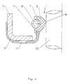
- Figure 1 shows a seal 1, sealing body 5 whereof comprises a recess 7 at the outer periphery in which a spring body 8, an annular helical spring made of metallic material, is disposed, which increases the contact pressure of sealing body 5 on machine element 12 to be sealed and also maintains the latter at low temperatures.
- Figure 1 shows a seal 1, sealing body 5 whereof comprises a recess 7 at the outer periphery in which a spring body 8, an annular helical spring made of metallic material, is disposed, which increases the contact pressure of sealing body 5 on machine element 12 to be sealed and also maintains the latter at low temperatures.
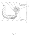
- sealing element 3 is provided with a coating 9 on one side, on the side facing the medium to be sealed. Coating 9 is formed from the same material and in one piece with sealing body 5.
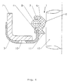
- Figure 3 shows a seal 1. wherein sealing element 3 and free end 4 belonging to sealing element 3 are designed in such a way that the radial pressing of sealing body 5 on the machine element to be sealed is sufficient and an additional spring body is not required.
- Figure 4 shows a seal according to figure 1 , wherein sealing body 5 in this embodiment is additional provided with a dust lip 11.
- Figure 5 shows a seal 1, wherein the sealing element 3 is provided with a coating 9 made of an elastomeric material on its free end 4, especially made of a fluorinated rubber compound.
- the coating 9 forms the sealing body 5.
- the advantage of this embodiment is the minimal material requirement of the elastomeric material.
Landscapes
- Engineering & Computer Science (AREA)
- General Engineering & Computer Science (AREA)
- Mechanical Engineering (AREA)
- Sealing With Elastic Sealing Lips (AREA)
- Gasket Seals (AREA)
- Sealing Devices (AREA)
Abstract
Description
- The invention relates to a seal, comprising a supporting body to which a disc-shaped sealing element is fixed, wherein the sealing element is fixed to the supporting body in such a way that it forms a static seal and comprises a free end.
- Such a seal is known from international application
WO 2008/009317 A1 . The previously known seal comprises an L-shaped supporting ring, to which a disc-shaped sealing element of PTFE is fixed, wherein the sealing element is fixed to the supporting ring in such a way that it surrounds the supporting ring at an end face and on the outside forms a static seal and on the inside comprises a projecting free end which forms the dynamic seal. The free end of the sealing element lies adjacent to the material to be sealed with radial pretensioning on account of the restoring force of the PTFE material. - Radial shaft sealing rings, which are used for machine elements for areas of use at low temperatures, i.e. temperatures which lie well below freezing point, are equipped with sealing lips made from an elastomere suitable for low-temperature applications. Temperatures of use which lie below the glass transition temperature of the elastomer used lead to embrittlement of the material and thus to an insufficient sealing effect of the sealing lip. Special fluorinated rubbers, for example, are an elastomer material group known for low temperatures of use. These special fluorinated rubbers admittedly have a lower glass transition temperature than usual fluorinated rubbers, but they are much more expensive.
- The problem underlying the invention is to develop further the previously described radial shaft sealing ring for low-temperature applications, in such a way that the latter can be produced more cost-effectively.
- This problem is solved with the features of
claim 1. The sub-claims relate to advantageous embodiments. - To solve the problem, a sealing body from which a dynamic sealing edge is formed is disposed at the free end, the sealing body being made from a material differing from the sealing element. The sealing element is fixed to the supporting body in such a way that its projects from the supporting body on the inside and forms a free end. This free end is mobile, so that the sealing body is fixed to the sealing element in a spring-mounted manner. It is particularly advantageous here that the sealing body has a comparatively small volume, so that the material requirement for the sealing body is low. The material costs can thus be reduced, especially if the specifications require that the dynamically-sealing sealing body lying adjacent to the machine element to be sealed is made from an elastomer with high procurement costs.
- The sealing element can be made from PTFE. PTFE can be used in a large temperature range. It has a glass transition temperature of approximately 70°C.
- This means that the material becomes brittle only below this temperature. Generally, however, PTFE exhibits worse elastic properties compared to elastomer sealing materials, such as fluorinated rubbers (FKM, FPM, FFKM). It is not able therefore to function as a dynamic sealing lip in all cases. In these cases, in which more elastic properties of the sealing lip are required, provision is made according to the invention to provide the free end of the sealing element formed from PTFE with a sealing body made of an elastomer material. A further advantage of PTFE is its high chemical resistance.
- The sealing body can be made from a fluorinated rubber. Fluorinated rubbers are elastomers which have a high chemical resistance and a large spectrum of temperature applications. Furthermore, fluorinated rubbers display advantageous ageing properties. Special fluorinated rubber compounds display a particularly advantageous low-temperature resistance. Seals made of such compounds can be used down to -40°C. Such compounds, however, are very expensive, so that the inventive effect emerges particularly advantageously with these compounds.
- At the outer periphery, the sealing body can have a recess in which a spring body is disposed. A sealing element of PTFE, a washer, which has been produced from a tubular semi-finished product, already exerts a restoring force by itself, which leads to pressing of the sealing body in a radial direction against the machine element to be sealed. At low temperatures, and depending on guidance accuracy of the shaft, this restoring force could be not sufficient, so that the necessary contact pressure of the sealing body cannot be guaranteed solely by the sealing element. The spring body, for example an annular helical spring, increases the contact pressure of the sealing body and also maintains the latter at low temperatures.
- The sealing element can be provided with a coating at least on one side. The sealing element is thus protected against attack by aggressive media according to the provision of the coating on one side or on both sides.
- The sealing body and the coating can be designed made of the same material and in one piece. The binding area between sealing element and coating is thereby increased, so that the binding between sealing element and sealing body is improved with a minimally increased material requirement.
- The sealing element can cover an end face of the supporting body. As a result, the supporting body is protected against attack by aggressive media. A separate treatment of the supporting body, for example a coating, can be dispensed with. It may however be advisable to pre-treat the supporting body, for example by means of a plasma treatment, in order to improve the binding between sealing element and supporting body.
- The sealing body can be provided with a dust lip. The dust lip protects the actual dynamic sealing lip against coarser contamination.
- The supporting body can be designed L-shaped. Such supporting bodies can be produced particularly easily by stamping or also free from clippings from sheet metal strips.
- Several examples of embodiment of the seal according to the invention are explained in greater detail below with the aid of the figures. In the figures, in each case schematically:
- Fig. 1
- shows a seal whose sealing body is provided with a spring body;
- Fig. 2
- shows a seal whose sealing element is provided on one side with a coating;
- Fig. 3
- shows a seal without a spring body;
- Fig. 4
- shows a seal whose sealing body comprises a dust lip;
- Fig. 5
- shows a seal with a thin elastic coating on the PTFE lip.
- The figures show a
seal 1 with advantageous cold-running properties for low-temperature applications down to -40°C. Seal 1 comprises an L-shaped supportingbody 2, formed as a metal stamping, to which a disc-shaped sealing element 3 of PTFE is fixed.Sealing element 3 surrounds anend face 10 of supportingbody 2 and surroundsend face 10 in such a way that on the outside it forms a static seal and on the inside comprises afree end 4 which projects from the supporting body. Anannular sealing body 5 is disposed onfree end 4 in a firmly bonded manner and mobile in the radial direction, adynamic sealing edge 6 being formed from said sealing body. Sealingbody 5 is formed from a fluorinated rubber compound (FKM, FPM, FFKM) and is thus made from a material differing from sealingelement 3. Sealingbody 5 lies adjacent tomachine element 12 to be sealed in a sealing manner with elastic pretensioning due to the restoring force of sealingelement 3 formed from PTFE. -
Figure 1 shows aseal 1, sealingbody 5 whereof comprises arecess 7 at the outer periphery in which aspring body 8, an annular helical spring made of metallic material, is disposed, which increases the contact pressure of sealingbody 5 onmachine element 12 to be sealed and also maintains the latter at low temperatures. -
Figure 1 shows aseal 1, sealingbody 5 whereof comprises arecess 7 at the outer periphery in which aspring body 8, an annular helical spring made of metallic material, is disposed, which increases the contact pressure of sealingbody 5 onmachine element 12 to be sealed and also maintains the latter at low temperatures. In addition, sealingelement 3 is provided with acoating 9 on one side, on the side facing the medium to be sealed.Coating 9 is formed from the same material and in one piece with sealingbody 5. -
Figure 3 shows aseal 1. wherein sealingelement 3 andfree end 4 belonging to sealingelement 3 are designed in such a way that the radial pressing of sealingbody 5 on the machine element to be sealed is sufficient and an additional spring body is not required. -
Figure 4 shows a seal according tofigure 1 , wherein sealingbody 5 in this embodiment is additional provided with adust lip 11. -
Figure 5 shows aseal 1, wherein the sealingelement 3 is provided with acoating 9 made of an elastomeric material on itsfree end 4, especially made of a fluorinated rubber compound. Thecoating 9 forms the sealingbody 5. The advantage of this embodiment is the minimal material requirement of the elastomeric material.
Claims (10)
- A seal (1), comprising a supporting body (2) to which a disc-shaped sealing element (3) is fixed, wherein the sealing element (3) is fixed to the supporting body (2) in such a way that it forms a static seal and comprises a free end (4), characterised in that a sealing body (5) is disposed at the free end (4), from which sealing body a dynamic sealing edge (6) is formed, wherein the sealing body (5) is made from a material differing from the sealing element (3).
- The seal according to claim 1, characterised in that the sealing element (3) is made from PTFE.
- The seal according to claim 1 or 2, characterised in that the sealing body (5) is made from a fluorinated rubber.
- The seal according to any one of claims 1 to 3, characterised in that the sealing body (5) comprises a recess (7) at the outer periphery, in which a spring body (8) is disposed.
- The seal according to any one of claims 1 to 4, characterised in that the sealing element (3) is provided at least on one side with a coating (9).
- The seal according to claim 5, characterised in that the sealing body (5) and the coating (9) are formed from the same material and in one piece.
- The seal according to any one of claims 1 to 6, characterised in that the sealing element (3) covers an end face (10) of the supporting body (2).
- The seal according to any one of claims 1 to 7, characterised in that the sealing body (5) is provided with a dust lip (11).
- The seal according to any one of claims 1 to 8, characterised in that the supporting body (2) is designed L-shaped.
- The seal according to any one of claims 1 to 7, characterized in that the sealing body (5) is formed from the coating (9).
Priority Applications (7)
| Application Number | Priority Date | Filing Date | Title |
|---|---|---|---|
| EP09000774.1A EP2211076B1 (en) | 2009-01-21 | 2009-01-21 | Seal |
| KR1020100002285A KR20100085844A (en) | 2009-01-21 | 2010-01-11 | Seal |
| BRPI1000094-1A BRPI1000094A2 (en) | 2009-01-21 | 2010-01-19 | seal |
| RU2010101806/06A RU2437015C2 (en) | 2009-01-21 | 2010-01-20 | Packing |
| CN201010111530A CN101865290A (en) | 2009-01-21 | 2010-01-20 | Seal arrangement |
| JP2010010016A JP2010169264A (en) | 2009-01-21 | 2010-01-20 | Seal |
| US12/691,144 US8496252B2 (en) | 2009-01-21 | 2010-01-21 | Seal |
Applications Claiming Priority (1)
| Application Number | Priority Date | Filing Date | Title |
|---|---|---|---|
| EP09000774.1A EP2211076B1 (en) | 2009-01-21 | 2009-01-21 | Seal |
Publications (2)
| Publication Number | Publication Date |
|---|---|
| EP2211076A1 true EP2211076A1 (en) | 2010-07-28 |
| EP2211076B1 EP2211076B1 (en) | 2015-09-02 |
Family
ID=40720077
Family Applications (1)
| Application Number | Title | Priority Date | Filing Date |
|---|---|---|---|
| EP09000774.1A Not-in-force EP2211076B1 (en) | 2009-01-21 | 2009-01-21 | Seal |
Country Status (7)
| Country | Link |
|---|---|
| US (1) | US8496252B2 (en) |
| EP (1) | EP2211076B1 (en) |
| JP (1) | JP2010169264A (en) |
| KR (1) | KR20100085844A (en) |
| CN (1) | CN101865290A (en) |
| BR (1) | BRPI1000094A2 (en) |
| RU (1) | RU2437015C2 (en) |
Families Citing this family (5)
| Publication number | Priority date | Publication date | Assignee | Title |
|---|---|---|---|---|
| JP5475866B2 (en) * | 2010-03-08 | 2014-04-16 | 本田技研工業株式会社 | Automotive engine oil seal |
| JP5475867B2 (en) * | 2010-03-08 | 2014-04-16 | 本田技研工業株式会社 | Automotive transmission oil seal |
| EP2400189B1 (en) * | 2010-06-25 | 2014-04-02 | Dichtungstechnik G. Bruss GmbH & Co. KG | Rotary shaft lip seal, use of same and method of producing same |
| EP3543568B1 (en) * | 2018-03-19 | 2021-01-06 | Carl Freudenberg KG | Sealing ring, sealing arrangement and use of a sealing arrangement |
| IT201900016034A1 (en) * | 2019-09-11 | 2021-03-11 | Skf Ab | SEALING DEVICE IN PARTICULAR FOR SHOCK ABSORBER STEMS |
Citations (5)
| Publication number | Priority date | Publication date | Assignee | Title |
|---|---|---|---|---|
| JPS6084479A (en) * | 1983-10-17 | 1985-05-13 | Nok Corp | Preparation of oil seal |
| EP1024318A2 (en) * | 1999-01-29 | 2000-08-02 | Freudenberg-NOK General Partnership | Reverse seal |
| EP1462686A1 (en) * | 2003-03-27 | 2004-09-29 | Carl Freudenberg KG | Sealing ring |
| WO2008009317A1 (en) | 2006-07-20 | 2008-01-24 | Carl Freudenberg Kg | Seal |
| DE102006059398A1 (en) * | 2006-12-08 | 2008-06-12 | Kaco Gmbh + Co. Kg | Seal, preferably rotary shaft seal, has static sealing component and dynamic sealing component which are part of sealing element fastened on support body, wherein sealing element is formed as deformable annular disc |
Family Cites Families (16)
| Publication number | Priority date | Publication date | Assignee | Title |
|---|---|---|---|---|
| US4426094A (en) * | 1983-01-20 | 1984-01-17 | Dana Corporation | Non-metallic guard for sealing lips |
| JPH0774103B2 (en) | 1986-12-27 | 1995-08-09 | 日本碍子株式会社 | High hardness silicon nitride sintered body |
| JPH0448368Y2 (en) * | 1987-04-18 | 1992-11-13 | ||
| DE4141999C2 (en) * | 1991-12-19 | 1997-06-12 | Blohm Voss Ag | Lip seal for sealing a shaft, especially a ship propeller shaft |
| US5697710A (en) * | 1995-10-20 | 1997-12-16 | Nok Corporation | Bearing seals and bearing and seal assemblies |
| DE19711400C2 (en) * | 1997-03-19 | 2001-12-06 | Freudenberg Carl Fa | Radial shaft seal |
| US6367811B1 (en) * | 1998-11-24 | 2002-04-09 | Mitsubishi Cable Industries, Ltd. | Rotation shaft seal |
| KR100739402B1 (en) * | 1999-09-27 | 2007-07-18 | 가부시키가이샤 제이텍트 | Seal and rotating assembly using it |
| DE10024026A1 (en) * | 2000-05-16 | 2001-11-29 | Freudenberg Carl Fa | Sealing sleeve, especially for installation spaces with small dimensions |
| DE10352674B4 (en) * | 2003-11-11 | 2007-07-19 | Federal-Mogul Sealing Systems Bretten Gmbh | poetry |
| DE102004002978A1 (en) * | 2004-01-21 | 2005-08-18 | Carl Freudenberg Kg | Radial shaft seal |
| BRPI0402110A (en) * | 2004-05-28 | 2005-02-15 | Sabo Ind & Comercio Ltda | Improvement in ptfe sealing device |
| US7854433B2 (en) * | 2005-02-24 | 2010-12-21 | Freudenberg-Nok General Partnership | Dynamic seal |
| DE102006059397B4 (en) * | 2006-12-08 | 2017-02-09 | Kaco Gmbh + Co. Kg | poetry |
| CN201078474Y (en) * | 2007-09-14 | 2008-06-25 | 邓伦胜 | Self-positioning split type cloth gripping oil seal |
| RU74679U1 (en) * | 2007-12-03 | 2008-07-10 | Общество с ограниченной ответственностью Научно-производственное объединение "РОСТАР" | CUFF |
-
2009
- 2009-01-21 EP EP09000774.1A patent/EP2211076B1/en not_active Not-in-force
-
2010
- 2010-01-11 KR KR1020100002285A patent/KR20100085844A/en not_active Ceased
- 2010-01-19 BR BRPI1000094-1A patent/BRPI1000094A2/en not_active IP Right Cessation
- 2010-01-20 JP JP2010010016A patent/JP2010169264A/en active Pending
- 2010-01-20 RU RU2010101806/06A patent/RU2437015C2/en not_active IP Right Cessation
- 2010-01-20 CN CN201010111530A patent/CN101865290A/en active Pending
- 2010-01-21 US US12/691,144 patent/US8496252B2/en not_active Expired - Fee Related
Patent Citations (5)
| Publication number | Priority date | Publication date | Assignee | Title |
|---|---|---|---|---|
| JPS6084479A (en) * | 1983-10-17 | 1985-05-13 | Nok Corp | Preparation of oil seal |
| EP1024318A2 (en) * | 1999-01-29 | 2000-08-02 | Freudenberg-NOK General Partnership | Reverse seal |
| EP1462686A1 (en) * | 2003-03-27 | 2004-09-29 | Carl Freudenberg KG | Sealing ring |
| WO2008009317A1 (en) | 2006-07-20 | 2008-01-24 | Carl Freudenberg Kg | Seal |
| DE102006059398A1 (en) * | 2006-12-08 | 2008-06-12 | Kaco Gmbh + Co. Kg | Seal, preferably rotary shaft seal, has static sealing component and dynamic sealing component which are part of sealing element fastened on support body, wherein sealing element is formed as deformable annular disc |
Also Published As
| Publication number | Publication date |
|---|---|
| US8496252B2 (en) | 2013-07-30 |
| EP2211076B1 (en) | 2015-09-02 |
| KR20100085844A (en) | 2010-07-29 |
| CN101865290A (en) | 2010-10-20 |
| RU2437015C2 (en) | 2011-12-20 |
| RU2010101806A (en) | 2011-07-27 |
| BRPI1000094A2 (en) | 2011-03-29 |
| JP2010169264A (en) | 2010-08-05 |
| US20100181732A1 (en) | 2010-07-22 |
Similar Documents
| Publication | Publication Date | Title |
|---|---|---|
| EP2211076B1 (en) | Seal | |
| CN104379974B (en) | mechanical seal | |
| RU2368825C1 (en) | Sealing ring | |
| JP6314487B2 (en) | Sealing device | |
| EP2044351B1 (en) | Method for the production of a seal | |
| JP2001317636A (en) | Lip type seal | |
| EP3546775B1 (en) | Sintered bearing | |
| EP1760371B1 (en) | Sealing device | |
| US7942423B2 (en) | Lip type seal | |
| KR101362716B1 (en) | Rotation shaft seal | |
| US20190072182A1 (en) | Sealing device | |
| CN101517286A (en) | Sealing device | |
| US11221074B2 (en) | Mechanical seal | |
| JP2000074223A (en) | Oil seal | |
| JPWO2011024523A1 (en) | Contamination seal device | |
| CN110520658A (en) | The arrangement of sealing element | |
| JP4958445B2 (en) | Mechanical seal device for compressor | |
| JP2001074145A (en) | Rotating shaft seal | |
| JP2006177500A (en) | Mechanical seal | |
| JP2001050397A (en) | Lip type seal | |
| JP2012013213A (en) | Mechanical seal | |
| CN202883744U (en) | Dust-proof ring | |
| JP2011080578A (en) | Mechanical seal | |
| JP2000304138A (en) | Lip type seal | |
| JP2005265161A (en) | Seal for fuel injection pump |
Legal Events
| Date | Code | Title | Description |
|---|---|---|---|
| PUAI | Public reference made under article 153(3) epc to a published international application that has entered the european phase |
Free format text: ORIGINAL CODE: 0009012 |
|
| 17P | Request for examination filed |
Effective date: 20091009 |
|
| AK | Designated contracting states |
Kind code of ref document: A1 Designated state(s): AT BE BG CH CY CZ DE DK EE ES FI FR GB GR HR HU IE IS IT LI LT LU LV MC MK MT NL NO PL PT RO SE SI SK TR |
|
| AX | Request for extension of the european patent |
Extension state: AL BA RS |
|
| AKX | Designation fees paid |
Designated state(s): AT BE BG CH CY CZ DE DK EE ES FI FR GB GR HR HU IE IS IT LI LT LU LV MC MK MT NL NO PL PT RO SE SI SK TR |
|
| GRAP | Despatch of communication of intention to grant a patent |
Free format text: ORIGINAL CODE: EPIDOSNIGR1 |
|
| INTG | Intention to grant announced |
Effective date: 20150603 |
|
| GRAS | Grant fee paid |
Free format text: ORIGINAL CODE: EPIDOSNIGR3 |
|
| GRAA | (expected) grant |
Free format text: ORIGINAL CODE: 0009210 |
|
| AK | Designated contracting states |
Kind code of ref document: B1 Designated state(s): AT BE BG CH CY CZ DE DK EE ES FI FR GB GR HR HU IE IS IT LI LT LU LV MC MK MT NL NO PL PT RO SE SI SK TR |
|
| REG | Reference to a national code |
Ref country code: GB Ref legal event code: FG4D |
|
| REG | Reference to a national code |
Ref country code: AT Ref legal event code: REF Ref document number: 746821 Country of ref document: AT Kind code of ref document: T Effective date: 20150915 Ref country code: CH Ref legal event code: EP |
|
| REG | Reference to a national code |
Ref country code: IE Ref legal event code: FG4D |
|
| REG | Reference to a national code |
Ref country code: DE Ref legal event code: R096 Ref document number: 602009033274 Country of ref document: DE |
|
| REG | Reference to a national code |
Ref country code: AT Ref legal event code: MK05 Ref document number: 746821 Country of ref document: AT Kind code of ref document: T Effective date: 20150902 |
|
| REG | Reference to a national code |
Ref country code: FR Ref legal event code: PLFP Year of fee payment: 8 |
|
| PG25 | Lapsed in a contracting state [announced via postgrant information from national office to epo] |
Ref country code: LV Free format text: LAPSE BECAUSE OF FAILURE TO SUBMIT A TRANSLATION OF THE DESCRIPTION OR TO PAY THE FEE WITHIN THE PRESCRIBED TIME-LIMIT Effective date: 20150902 Ref country code: GR Free format text: LAPSE BECAUSE OF FAILURE TO SUBMIT A TRANSLATION OF THE DESCRIPTION OR TO PAY THE FEE WITHIN THE PRESCRIBED TIME-LIMIT Effective date: 20151203 Ref country code: NO Free format text: LAPSE BECAUSE OF FAILURE TO SUBMIT A TRANSLATION OF THE DESCRIPTION OR TO PAY THE FEE WITHIN THE PRESCRIBED TIME-LIMIT Effective date: 20151202 Ref country code: LT Free format text: LAPSE BECAUSE OF FAILURE TO SUBMIT A TRANSLATION OF THE DESCRIPTION OR TO PAY THE FEE WITHIN THE PRESCRIBED TIME-LIMIT Effective date: 20150902 Ref country code: FI Free format text: LAPSE BECAUSE OF FAILURE TO SUBMIT A TRANSLATION OF THE DESCRIPTION OR TO PAY THE FEE WITHIN THE PRESCRIBED TIME-LIMIT Effective date: 20150902 |
|
| REG | Reference to a national code |
Ref country code: LT Ref legal event code: MG4D Ref country code: NL Ref legal event code: MP Effective date: 20150902 |
|
| PG25 | Lapsed in a contracting state [announced via postgrant information from national office to epo] |
Ref country code: PL Free format text: LAPSE BECAUSE OF FAILURE TO SUBMIT A TRANSLATION OF THE DESCRIPTION OR TO PAY THE FEE WITHIN THE PRESCRIBED TIME-LIMIT Effective date: 20150902 Ref country code: AT Free format text: LAPSE BECAUSE OF FAILURE TO SUBMIT A TRANSLATION OF THE DESCRIPTION OR TO PAY THE FEE WITHIN THE PRESCRIBED TIME-LIMIT Effective date: 20150902 Ref country code: SE Free format text: LAPSE BECAUSE OF FAILURE TO SUBMIT A TRANSLATION OF THE DESCRIPTION OR TO PAY THE FEE WITHIN THE PRESCRIBED TIME-LIMIT Effective date: 20150902 Ref country code: ES Free format text: LAPSE BECAUSE OF FAILURE TO SUBMIT A TRANSLATION OF THE DESCRIPTION OR TO PAY THE FEE WITHIN THE PRESCRIBED TIME-LIMIT Effective date: 20150902 |
|
| PG25 | Lapsed in a contracting state [announced via postgrant information from national office to epo] |
Ref country code: EE Free format text: LAPSE BECAUSE OF FAILURE TO SUBMIT A TRANSLATION OF THE DESCRIPTION OR TO PAY THE FEE WITHIN THE PRESCRIBED TIME-LIMIT Effective date: 20150902 Ref country code: IS Free format text: LAPSE BECAUSE OF FAILURE TO SUBMIT A TRANSLATION OF THE DESCRIPTION OR TO PAY THE FEE WITHIN THE PRESCRIBED TIME-LIMIT Effective date: 20160102 Ref country code: CZ Free format text: LAPSE BECAUSE OF FAILURE TO SUBMIT A TRANSLATION OF THE DESCRIPTION OR TO PAY THE FEE WITHIN THE PRESCRIBED TIME-LIMIT Effective date: 20150902 Ref country code: IT Free format text: LAPSE BECAUSE OF FAILURE TO SUBMIT A TRANSLATION OF THE DESCRIPTION OR TO PAY THE FEE WITHIN THE PRESCRIBED TIME-LIMIT Effective date: 20150902 Ref country code: NL Free format text: LAPSE BECAUSE OF FAILURE TO SUBMIT A TRANSLATION OF THE DESCRIPTION OR TO PAY THE FEE WITHIN THE PRESCRIBED TIME-LIMIT Effective date: 20150902 Ref country code: SK Free format text: LAPSE BECAUSE OF FAILURE TO SUBMIT A TRANSLATION OF THE DESCRIPTION OR TO PAY THE FEE WITHIN THE PRESCRIBED TIME-LIMIT Effective date: 20150902 |
|
| PG25 | Lapsed in a contracting state [announced via postgrant information from national office to epo] |
Ref country code: BE Free format text: LAPSE BECAUSE OF NON-PAYMENT OF DUE FEES Effective date: 20160131 Ref country code: RO Free format text: LAPSE BECAUSE OF FAILURE TO SUBMIT A TRANSLATION OF THE DESCRIPTION OR TO PAY THE FEE WITHIN THE PRESCRIBED TIME-LIMIT Effective date: 20150902 Ref country code: PT Free format text: LAPSE BECAUSE OF FAILURE TO SUBMIT A TRANSLATION OF THE DESCRIPTION OR TO PAY THE FEE WITHIN THE PRESCRIBED TIME-LIMIT Effective date: 20160104 |
|
| REG | Reference to a national code |
Ref country code: DE Ref legal event code: R097 Ref document number: 602009033274 Country of ref document: DE |
|
| PLBE | No opposition filed within time limit |
Free format text: ORIGINAL CODE: 0009261 |
|
| STAA | Information on the status of an ep patent application or granted ep patent |
Free format text: STATUS: NO OPPOSITION FILED WITHIN TIME LIMIT |
|
| 26N | No opposition filed |
Effective date: 20160603 |
|
| PG25 | Lapsed in a contracting state [announced via postgrant information from national office to epo] |
Ref country code: DK Free format text: LAPSE BECAUSE OF FAILURE TO SUBMIT A TRANSLATION OF THE DESCRIPTION OR TO PAY THE FEE WITHIN THE PRESCRIBED TIME-LIMIT Effective date: 20150902 Ref country code: LU Free format text: LAPSE BECAUSE OF FAILURE TO SUBMIT A TRANSLATION OF THE DESCRIPTION OR TO PAY THE FEE WITHIN THE PRESCRIBED TIME-LIMIT Effective date: 20160121 Ref country code: SI Free format text: LAPSE BECAUSE OF FAILURE TO SUBMIT A TRANSLATION OF THE DESCRIPTION OR TO PAY THE FEE WITHIN THE PRESCRIBED TIME-LIMIT Effective date: 20150902 |
|
| REG | Reference to a national code |
Ref country code: CH Ref legal event code: PL |
|
| GBPC | Gb: european patent ceased through non-payment of renewal fee |
Effective date: 20160121 |
|
| PG25 | Lapsed in a contracting state [announced via postgrant information from national office to epo] |
Ref country code: MC Free format text: LAPSE BECAUSE OF FAILURE TO SUBMIT A TRANSLATION OF THE DESCRIPTION OR TO PAY THE FEE WITHIN THE PRESCRIBED TIME-LIMIT Effective date: 20150902 |
|
| PG25 | Lapsed in a contracting state [announced via postgrant information from national office to epo] |
Ref country code: GB Free format text: LAPSE BECAUSE OF NON-PAYMENT OF DUE FEES Effective date: 20160121 Ref country code: CH Free format text: LAPSE BECAUSE OF NON-PAYMENT OF DUE FEES Effective date: 20160131 Ref country code: LI Free format text: LAPSE BECAUSE OF NON-PAYMENT OF DUE FEES Effective date: 20160131 |
|
| REG | Reference to a national code |
Ref country code: IE Ref legal event code: MM4A |
|
| PG25 | Lapsed in a contracting state [announced via postgrant information from national office to epo] |
Ref country code: BE Free format text: LAPSE BECAUSE OF FAILURE TO SUBMIT A TRANSLATION OF THE DESCRIPTION OR TO PAY THE FEE WITHIN THE PRESCRIBED TIME-LIMIT Effective date: 20150902 |
|
| REG | Reference to a national code |
Ref country code: FR Ref legal event code: PLFP Year of fee payment: 9 |
|
| PG25 | Lapsed in a contracting state [announced via postgrant information from national office to epo] |
Ref country code: IE Free format text: LAPSE BECAUSE OF NON-PAYMENT OF DUE FEES Effective date: 20160121 |
|
| PGFP | Annual fee paid to national office [announced via postgrant information from national office to epo] |
Ref country code: DE Payment date: 20170131 Year of fee payment: 9 Ref country code: FR Payment date: 20170126 Year of fee payment: 9 |
|
| PG25 | Lapsed in a contracting state [announced via postgrant information from national office to epo] |
Ref country code: MT Free format text: LAPSE BECAUSE OF FAILURE TO SUBMIT A TRANSLATION OF THE DESCRIPTION OR TO PAY THE FEE WITHIN THE PRESCRIBED TIME-LIMIT Effective date: 20150902 |
|
| PG25 | Lapsed in a contracting state [announced via postgrant information from national office to epo] |
Ref country code: HU Free format text: LAPSE BECAUSE OF FAILURE TO SUBMIT A TRANSLATION OF THE DESCRIPTION OR TO PAY THE FEE WITHIN THE PRESCRIBED TIME-LIMIT; INVALID AB INITIO Effective date: 20090121 Ref country code: CY Free format text: LAPSE BECAUSE OF FAILURE TO SUBMIT A TRANSLATION OF THE DESCRIPTION OR TO PAY THE FEE WITHIN THE PRESCRIBED TIME-LIMIT Effective date: 20150902 |
|
| PG25 | Lapsed in a contracting state [announced via postgrant information from national office to epo] |
Ref country code: MK Free format text: LAPSE BECAUSE OF FAILURE TO SUBMIT A TRANSLATION OF THE DESCRIPTION OR TO PAY THE FEE WITHIN THE PRESCRIBED TIME-LIMIT Effective date: 20150902 Ref country code: HR Free format text: LAPSE BECAUSE OF FAILURE TO SUBMIT A TRANSLATION OF THE DESCRIPTION OR TO PAY THE FEE WITHIN THE PRESCRIBED TIME-LIMIT Effective date: 20150902 Ref country code: MT Free format text: LAPSE BECAUSE OF FAILURE TO SUBMIT A TRANSLATION OF THE DESCRIPTION OR TO PAY THE FEE WITHIN THE PRESCRIBED TIME-LIMIT Effective date: 20160131 Ref country code: TR Free format text: LAPSE BECAUSE OF FAILURE TO SUBMIT A TRANSLATION OF THE DESCRIPTION OR TO PAY THE FEE WITHIN THE PRESCRIBED TIME-LIMIT Effective date: 20150902 |
|
| PG25 | Lapsed in a contracting state [announced via postgrant information from national office to epo] |
Ref country code: BG Free format text: LAPSE BECAUSE OF FAILURE TO SUBMIT A TRANSLATION OF THE DESCRIPTION OR TO PAY THE FEE WITHIN THE PRESCRIBED TIME-LIMIT Effective date: 20150902 |
|
| REG | Reference to a national code |
Ref country code: DE Ref legal event code: R119 Ref document number: 602009033274 Country of ref document: DE |
|
| PG25 | Lapsed in a contracting state [announced via postgrant information from national office to epo] |
Ref country code: DE Free format text: LAPSE BECAUSE OF NON-PAYMENT OF DUE FEES Effective date: 20180801 Ref country code: FR Free format text: LAPSE BECAUSE OF NON-PAYMENT OF DUE FEES Effective date: 20180131 |
|
| REG | Reference to a national code |
Ref country code: FR Ref legal event code: ST Effective date: 20180928 |