EP2210813B2 - Method and device for packaging small articles - Google Patents
Method and device for packaging small articles Download PDFInfo
- Publication number
- EP2210813B2 EP2210813B2 EP10004445.2A EP10004445A EP2210813B2 EP 2210813 B2 EP2210813 B2 EP 2210813B2 EP 10004445 A EP10004445 A EP 10004445A EP 2210813 B2 EP2210813 B2 EP 2210813B2
- Authority
- EP
- European Patent Office
- Prior art keywords
- head
- pick
- article
- packing
- packaging
- Prior art date
- Legal status (The legal status is an assumption and is not a legal conclusion. Google has not performed a legal analysis and makes no representation as to the accuracy of the status listed.)
- Not-in-force
Links
Images


Classifications
-
- B—PERFORMING OPERATIONS; TRANSPORTING
- B65—CONVEYING; PACKING; STORING; HANDLING THIN OR FILAMENTARY MATERIAL
- B65B—MACHINES, APPARATUS OR DEVICES FOR, OR METHODS OF, PACKAGING ARTICLES OR MATERIALS; UNPACKING
- B65B11/00—Wrapping, e.g. partially or wholly enclosing, articles or quantities of material, in strips, sheets or blanks, of flexible material
- B65B11/06—Wrapping articles, or quantities of material, by conveying wrapper and contents in common defined paths
- B65B11/28—Wrapping articles, or quantities of material, by conveying wrapper and contents in common defined paths in a curved path, e.g. on rotary tables or turrets
- B65B11/30—Wrapping articles, or quantities of material, by conveying wrapper and contents in common defined paths in a curved path, e.g. on rotary tables or turrets to fold the wrappers in tubular form about contents
- B65B11/34—Wrapping articles, or quantities of material, by conveying wrapper and contents in common defined paths in a curved path, e.g. on rotary tables or turrets to fold the wrappers in tubular form about contents the ends of the tube being subsequently twisted
-
- B—PERFORMING OPERATIONS; TRANSPORTING
- B65—CONVEYING; PACKING; STORING; HANDLING THIN OR FILAMENTARY MATERIAL
- B65B—MACHINES, APPARATUS OR DEVICES FOR, OR METHODS OF, PACKAGING ARTICLES OR MATERIALS; UNPACKING
- B65B25/00—Packaging other articles presenting special problems
- B65B25/005—Packaging other articles presenting special problems packaging of confectionery
- B65B25/006—Packaging other articles presenting special problems packaging of confectionery packaging of lollipops
Definitions
- the invention relates to a method and an apparatus for packaging small-sized articles, in particular with a handle (Lollipop).
- both intermittent packaging machines and packaging machines which operate on the continuous operation principle, with packaging machines in the high performance area generally require the application of a continuous working principle, otherwise beside inevitable Loss times also the product and packaging material accelerations stand in the way of higher performance requirements.
- Known packaging machine Lollipops are separated from a supply in a substantially in a horizontal deployment plane article-task and - singularized, and the isolated Lollipops are removed from the pockets by means of a removal head, by fixed thereto on a plate gripper assemblies and then handed over to the packaging head.
- a swivel plate is used in conjunction with a base plate and a stalk gripper which grips the stem.
- the invention is therefore an object of the invention to provide a method and apparatus for packaging small-sized items, especially with a handle, which allow to achieve higher packaging quality with high packaging quality and to create the conditions, even in the packaging of complicated items in the High-performance area. In particular, a higher quality packaging for the article is to be achieved.
- the methods and apparatus of the present invention are particularly advantageous in that they are the first in the field of continuously operating machines, i.
- the articles are picked up by a rotating removal head and passed on to a rotating packing head and are preferably dispensed after completion of the product packaging by a dispensing device.
- the inventive method is particularly advantageous in that already in the area of a first device after receiving a single article, a packaging supply takes place and the article is passed along with an associated piece of packaging material to a second device, which causes as genuinely packaging head, the formation of the article packaging.
- the new methods and devices are provided, in particular with regard to the packaging of articles with handles (lollipops).
- the method according to the invention is characterized in particular by the fact that the reception of the product, i. the collection on the stem in close proximity to the ball of the article and not as previously done at the exposed end of the stem.
- the device according to the invention is also advantageously further developed in that the packaging material supply is displaced into the removal head, whereas hitherto a separate gripper head has been provided between the removal head and the packing head of continuously operating machines is.
- the first head in the machine which receives the individual articles from an article-feeding and separating device, such as a separating disk, thus also contains the means previously associated with a separate gripper head for feeding packaging material into the removal head to the article and the article together with the packaging material to be delivered directly from the removal head to the packing head.
- the present application relates, in particular, to the packaging of small-sized articles with a stem, so-called lollipops, without being limited thereto.
- Such articles have not hitherto been able to be packaged with high performance machines which have a product output of e.g. equip approx. 1,000 pieces per minute.
- An advantageous process for the packaging of such products according to the working principle of continuously operating packaging machines is that the isolated, a stem having articles are not taken as before on the free end of the stem, but are included in the range of an article-side end of the stem, i. immediately or as close as possible behind the ball of the product. This results in the advantage that e.g. Positional error of the stem to the ball does not affect the product handling, so that a very safe product removal takes place, and tolerances (for example, eccentricities between stem and ball) have no influence on the further packaging process.
- Such small-sized products, and also the stemmed articles considered here as an embodiment thereof, are occasionally packaged in a wrapper with a rotary wing wrap.
- heated rotary grippers are used, which allow a heat seal and thus high seal strength and quality of the package in the transition from the stem to the ball of the article .
- a heated rotary gripper could also be used for the formation of a rotary vane on the side opposite the handle of the article or are such rotary gripper even when using heat-sealable packaging films for packaging products in double twisting applicable (article without stem), or it can also for the lolling of stemmed articles may be used with higher recovery packaging film without affecting the appearance or sealing of the lolly.
- the rotary blades on the opposite side of the stem of the article are formed here but with conventional (unheated) rotary grippers as simple twist stops.
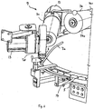
- FIG. 1 shows a packaging machine 100, which operates on the continuous principle, the articles A (see. Fig. 4 ) of a feeding and separating device 1, which is located on a horizontal U-profile frame 1 a of the machine (the latter is supported by machine feet 1 b to the ground) by a removal head 10 which is about a rotation axis 11 (FIG. Fig. 5 ) is rotatably received continuously and passed together with a piece of packaging material 12 to a packing head 20, which also about a stationary axis of rotation 21 (FIG. Fig.
- a front rotary head 60 coaxially disposed in front of the packing head 20 is omitted for clarity, while a rear rotary head 70 is shown as part of a rotating station 80.
- the packaging machine 100 is characterized in that it has only two packaging-essential, article-carrying heads, namely the removal head 10 and the packing head 20 between finished-packed article A and receiving the article A from the article feeding and separating device 1, whereby the packaging process significantly condensed, accelerated and made more efficient.
- the delivery wheel 50 is only an auxiliary device independent of the packing operation.
- article A with working speeds of eg about 1,000 cycles per minute, ie in the high-performance area, too
- the articles A are those which consist of a ball of hard caramel or other sweetener material attached to a stem A1.
- the ball of the article A is designated A2.
- arrows K, L, M, N, O, P denote the respective directions of rotation of distributor disc 2 (arrow K), feeding ring 3 (arrow L), removal head 10 (arrow M), packing head 20 (arrow N), dispensing wheel 50 (arrow O) and conveying direction of the delivery belt 40 (arrow P).
- Fig. 2 shows as a detail schematically the article-task and -Zeller 1, ie a separating disc 2, which in a known manner from its axis 2a sloping towards the outside, along the outer periphery of the separating disc 2 astancering 3 with pockets 4 for receiving the ball A2 of the article A is provided, on whose outer circumference pass over the pockets 4 in receiving slots 5, in which, with the product position being correct, the respective handle A1 of the article A is received radially outward (cf. Fig. 4 and 5 ).
- a Farmweiser 6 on the separating disc 2 provides a brush system 7 with individually driven brushes 7b, 7c, 7d in conjunction with a coil 7a, that the pockets 4 ofassiringes 3 with the products A (Ball A2) filled and located on the article A.
- Stems by the brush system 7 and the coil 7a are folded radially outwards, so that they are received in the receiving slots 5 with radially outwardly facing stem A1 (see. 4 to 6 ).
- An outer cover 8 ensures the shielding of the separating disc 2 to the outside.
- FIG. 3 and 4 are in different perspective and schematic representation again details on the one hand of the brush system 7 ( Fig. 3 ) and an empty-cycle sensor device 9 explained below. It clarifies Fig. 3 again, the different geometries of the brushes 7b, 7c, 7d, wherein the brush 7b forms a substantially elongated cylindrical body, with a first cylindrical portion 7b1, and a leading conical portion 7b2 with increasing diameter, for sorting the article A with the balls A2 in the pockets 4, which also participates in this function, the cylindrical brush 7c.
- the disk-shaped, in its width about the width ofoptionringes 3 corresponding brush 7c is used again for secure fixing of the products A (in Fig. 3 not shown) in the pockets 4. Small three-phase motors 13 individually drive each of the brushes 7b, 7c, 7d.
- Upstream of a removal position for the article A is an empty cycle sensor device 9, which scans in the present embodiment by means of a forked light barrier 15, the stems A1 of Article A, wherein downstream of the removal position a blower (blower nozzle) 16 is for articles that without Stem (so only as a ball) are in one of the pockets 4 and can not be processed.
- a blower (blower nozzle) 16 is for articles that without Stem (so only as a ball) are in one of the pockets 4 and can not be processed.
- the rail 14 are not provided so that the articles can fall freely down into a corresponding collection container.
- the gravitational force for product removal would not be sufficient, so that forcible ejection with defective articles without stem is provided by means of the blower 16.
- a packaging means feed device is stopped, so that in this case no piece of packaging material 12 is guided into the removal head 10, since then there is no article A at the corresponding point of the removal head 10.
- a positioning bracket 17 provided above the charging ring 3 and in the area above the stems A1 likewise serves for the correct positioning of the articles A and thus the positioning security. In view of the high working speeds, the most error-free orientation of the separated articles A is important.
- brush system 7 for the reliable placement of the article A in the pockets 4 and thus to ensure a high degree of filling the mindfulringes 3 may also consist of a single mold brush having a correspondingly adapted geometry in individual sections to the here on three brushes 7b, 7c, 7d split placement function to ensure.
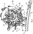
- Fig. 5 shows in a schematic and perspective partial representation of the article recording situation and the removal head 10 at the sampling point at which the article A are removed from the innovationring 3. Its direction of rotation is indicated by the arrow L, while the direction of rotation of the removal head 10 rotating about the axis of rotation 11 is designated by the arrow M in the clockwise direction.
- the articles A positioned in the feed ring 3 are placed on the stem A1 at an in Fig. 5 taken with E designated removal point, wherein the removal head 10 in the opposite direction to the direction of rotation of innovationringes 3 about the stationary axis of rotation 11 rotates.
- On its front are removal units 18, which in turn are pivotally mounted about a respective pivot axis 19 on the removal head 10.
- the removal head 10 is provided with six arranged in the circumferential direction at a uniform angular distance, pivotable removal units 18 (s. Fig. 6 ), wherein each removal unit 18 is associated with an additional and about a parallel pliers pivot axis 22 pivotable packaging tongs 23, as shown in Fig. 6 and 7 can be seen in more detail.
- the pliers pivot axis 22 extends parallel to the axis of rotation 11 of the removal head 10 and parallel to the pivot axis 19 of the removal units 18 (holding jaw pairs 24).
- Each removal unit 18 consists of a holding jaw pair 24 with a front in the direction of rotation of the removal head, front holding jaw 24a and a lying in the direction of rotation of the removal head 10, rear holding jaw 24b.
- the holding jaws 24a, 24b of each holding jaw pair 24 are each arranged on the common pivot axis 19, around which they perform an opening and closing movement for detecting and holding the handle A1 of the article A, as well as about this pivot axis 19 and the holding jaw pair 24 in total relative to Rotary movement of the removal head 10 about the rotation axis 11 is pivotable.
- the holding jaws 24a and 24b have, as clearly in the Fig. 5 and 6 shown, on their inner surfaces prismatic surfaces Z on, for safe and reliable gripping the respective cylindrical stem A1 of the article A. Moreover, contributes a large opening width of the holding jaw pairs 24 in addition to the prism shape to securely hold the stems A1, lead and thus to ensure extremely reliable product handling without relying on other management bodies.
- pivotable removal units 18 may be provided on the removal head 10.
- a Packstoffzange 23 which consists essentially of a U-shaped, ie slotted plate, and about a pliers pivot axis 22, the parallel for holding jaw pivot axis 19, but runs separately from this and also controlled independently, is pivotable.
- This packaging tongs 23 performs an accelerated movement and serves to create the possibility already between sampling point onsidering 3 and transfer point to the packing head 20 for the packaging of the article A required piece of packaging material 12 to the removal head 10 and this on the article A in conjunction to arrange with the holder of the same by the holding jaw pair 24.
- the removal head 10 is in "rolling engagement" with the packing head 20, which has in a comparable manner and number of packs 36, each of a relative to a rotation axis pivotable packing head holding jaw pairs 37, each associated with a separately pivotally mounted inner folder 38 , To carry out the wrapping and wrapping of the article A by a packaging tube, as will be explained below.
- the holding jaw pairs 24 of the same may also be rotatable about a running in a radial plane vertical axis, if a reorientation of the position of the product, for example, by 90 °, before feeding the piece of packaging required or useful , That is, the removal head can also in addition to a Position-reorientation of the article between removal position ofoptionring 3 and a transfer position on the packing head 20 serve.
- Fig. 8 schematically shows the interaction between the extraction head 10 and packing head 20 and illustrates the processes that take place respectively within the heads 10, 20.
- Fig. 8 Prior to transfer of the article A with the packaging material piece 12 to a packing head holding jaw pair 37 with the packing head holding jaws 37a and 37b, the piece of packaging material is placed in an angular or U-shape around the article (ie around the ball A2 thereof) Fig. 8 clarified (see also Fig. 15 ).
- the packing head holding jaws 37a, 37b of a packing head holding jaw pair 37 grip the article A, ie in each case with the packaging material piece 12 forming a packaging tube in connection with the wrapping of the packaging material 12 by means of the inner folder 38 and an outer folding sheet 39 (see FIG. Fig. 8 ).
- the cylindrical packing tube around the ball A2 is formed by means of a pivoting movement of the inner butterfly 38 and the circumferential movement along the outer folding sheet 39, as is familiar to those skilled in the art, so that further detailed explanations appear dispensable (vlg. Fig. 11 ).
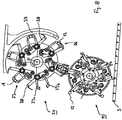
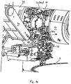
- the article A (Lollipop) on the one hand (above) to be wrapped with a rotary wing impact, while on the opposite side (on the stem A1) is a clean screwing and sealing the packaging material to the stem A1 for a consumer-friendly product is essential. Therefore, the packing head 20 is part of a rotating station 80 having a front turret 60 and a rear turret 70, as shown in FIG Fig. 13 is illustrated in a side view. For reasons of clarity, in particular the front rotary head 60 in the other representations, with the exception of Fig. 10 Not shown.
- Each of the front and rear turrets 60, 70 carries a number of rotary grippers 61, 71 corresponding to the packing units 36, which rotate synchronously with the rotation of the packing head 20 about the rotation axis 21, so that the relative position of the packing head holding jaw pairs 37 to the rotary grippers 61 , 71 with corresponding rotary gripper jaw pairs 62, 72 remains unchanged.
- Fig. 10 shows again in a perspective sectional view of the essential components of the packaging machine according to the present embodiment with the article-task and separation device 1 with theoptionring 3 and the product pockets 4, the removal head 10 with the removal units 18 including the packaging tongs 23 and the packing head 20 with the pack head holding jaw pairs 37 and the front rotary head 60, the rear rotary head 70 with the heated rotary grippers 71 and the delivery belt 40th
- the rotary gripper 71 of the rear rotary head 70 are completely different from the rotary grippers 61 of the front rotary head 60, the latter in this case of conventional construction, as in connection with a packaging material hose opposite to the stem of the product engaged and for the formation of a Rotary vane provided in a conventional manner.
- a rotary gripper 71 is used, that is, one of the number of packing head holding jaw pairs 37 corresponding and synchronous with these rotating number of rotary grippers 71, which are arranged on the rear rotary head 70 and in turn about a longitudinal axis 75 relative to the rotary head 70 are rotatable.
- the rotary gripper 71 with a relation to the rotational speed of the rotary head 70 higher rotational speed of this means each one mounted in the rotary head 70 rotary gripper shaft 75a about its longitudinal axis 75 rotate evenly.
- the rotary grippers 71 have Wheelgreiferbackencrue 72 with a rotary gripper jaw 72a and a rotary gripper jaw 72b, which perform an opening and closing movement about a longitudinal axis 75 orthogonal axis F (pivotal movement).
- a receiving recess 73 is provided, measured taking into account a diameter of the stem A1, which is received therein to screw the packaging tube end between stem A1 and rotary gripper 71 and smoothly seal to the stem A1, wherein the rotary gripper 71 about its longitudinal axis 75 the perform predicted rotational movement relative to the rotary head 70.
- the rotary gripper jaws 72a, 72b are offset relative to their storage section about the axis F by about 90 °, so that the handle A1 of the products consistently smooth and with appropriate clearance for sealing the packaging material can be encompassed.
- the rotary grippers 71 are distinguished from the rotary grippers 61 on the front rotary head 60 in that they are heated, and by heating the rotary gripper 31 or at least one of the rotary gripper jaws 72a, 72b may be a heat sealing and in conjunction with appropriate packing material a high Ansiegel27 on Stalk be realized in the area of the transition from the stem A1 to the ball A2.
- FIG. 12 Like the partial perspective view of the rear turret 70 according to FIG Fig. 12 illustrates the heating of the rotary gripper 71 or one or both rotary gripper jaws 72a, 72b each of the rotary gripper 71 (here always both rotary gripper jaws 72a, 72b heated) with the help of in the rotary gripper jaws 72a, 72b used heating cartridges (not shown here), if necessary But can also be used in the rotary gripper jaws 72a, 72b Schublättchen. The heating can also be carried out inductively or by laser or Elektronenstrahlbeetzschung.
- the power supply to the rotary grippers 71 of the rear rotary head 70 takes place taking into account the required rotational movement of the rotary gripper 71 about its longitudinal axis 75 (parallel to the axis of rotation 21 of the packing head 20 and the rear rotary head 70) via a first slip ring system 74 with slip rings 76 fixed to the housing and on the turret 70 supported contact brushes 77 and a second, not shown here and within the rotary head 70, in particular within rotary hook sleeves 81 (which are respectively connected to the rotary hook shafts 75 a, ie rotate at the rotational speed of the rotary gripper 71) arranged slip ring system, taking into account the rotation of Rotary gripper 71 about its longitudinal axis 75th
- a preferably non-contact temperature measurement (infrared temperature measurement) is provided which is part of a control circuit for controlling the heating power to the rotary gripper jaw pairs.
- a control circuit for controlling the heating power to the rotary gripper jaw pairs.
- the temperature monitoring or measurement could also be done directly via temperature sensor in the heated parts of the rotary gripper 71.
- the application of heated rotary grippers 71 is not limited to the present embodiment or stemmed products, but is also suitable for other applications, e.g. in the manufacture of rotary wing packaging or packaging in double-twist or single-twist (bag folding, Bunch folding), especially when using relatively strong or high return force having packaging materials.
- the dispenser which conveys the finished packaged articles (lollipops) to a delivery belt 40 via a delivery wheel 50 is shown schematically in FIG Fig. 1 shown.
- Fig. 14 shows the heated rotary gripper 71 schematically with the rotary gripper jaws 72a and 72b, a spirally wound to compensate for movement power supply line 78 and a line section 79 to the in Fig. 14 upper rotary gripper jaw 72a in which the heating cartridge is located.
- the power supply line 78 is electrically conductively connected to the second slip ring system within the rotary rotary gripper sleeve 81. It goes without saying that the first slip ring system 77 is conductively connected to the second slip ring system. An envelope of the line section 79 is grounded connected to the housing.
- Fig. 15 is shown schematically the product flow and the positional orientation of the article A in connection with the supply of a packaging.
- the upper packaging material supply 110 and the lower packaging material supply 120 are provided for automatic packaging change.
- the products A arrive from the separating device 1 via the removal head 10, into which the packaging material piece 12 is injected for transfer to the packing head 20, in which the product A is wrapped with a stem (Lollipop) and screwed on the one hand and sealed on the stem A1, on the other hand a rotary wing is closed.
- a circulation of about 270 ° of the finished packaged article is delivered from the packing head 20 to the dispensing wheel 50, which deposits the finished packaged article on the delivery belt 40 for removal from the machine.
- a continuously operating packaging machine is proposed for the first time, which has only two packaging-essential, product-carrying heads, the removal head and the packing head and the removal head is provided with additional functional organs for supplying packaging.
- the invention is not limited to the packaging of confectionery with stem, but it can under appropriate Adapting the principles set out above in a similar way, the packaging of other small-sized articles in other types of folding done.
- the influence of errors and tolerances resulting from product production is practically achieved Virtually eliminate influence on the further packaging process.
- the use of heated rotary grippers enables not only a clean sealing of packaging material on a stick, but in principle an improvement in the manufacture of packages with rotary blades.
- a packaging machine has a compact, compact structure and is characterized by a for complicated products, such as products with stem, previously unattained packaging performance in a range of 600 to 1000 strokes per minute, at the same time dynamic quiet running, the latter, in particular because of the continuous working principle.
- the invention provides, for the first time, a continuous product packaging machine with two product-processing heads, which makes it possible, in the case of complicated products (products with handle), in previously unachievable performance ranges of e.g. Approximately 1,000 work cycles per minute to penetrate, while a compact and product and packaging sparing structure to realize, combined with high product safety and low susceptibility to failure of the packaging device.
Description
Die Erfindung betrifft ein Verfahren und eine Vorrichtung zum Verpacken kleinstückiger Artikel, insbesondere mit einem Stiel (Lollipop).The invention relates to a method and an apparatus for packaging small-sized articles, in particular with a handle (Lollipop).
Zur Verpackung kleinstückiger Artikel wie Hart- oder Weichkaramellen, Pralinen oder anderer kleinstükkiger Süßwaren, sind sowohl intermittierend arbeitende Verpackungsmaschinen als auch Verpackungsmaschinen bekannt, die nach dem kontinuierlichen Arbeitsprinzip arbeiten, wobei Verpackungsmaschinen im Hochleistungsbereich im allgemeinen die Anwendung eines kontinuierlichen Arbeitsprinzips erfordern, da ansonsten neben unvermeidlichen Verlustzeiten auch die Produkt- und Verpackungsmaterialbeschleunigungen höheren Leistungsanforderungen im Wege stehen.For the packaging of small-sized items such as hard or soft caramels, chocolates or other kleinstükkiger confectionery, both intermittent packaging machines and packaging machines are known which operate on the continuous operation principle, with packaging machines in the high performance area generally require the application of a continuous working principle, otherwise beside inevitable Loss times also the product and packaging material accelerations stand in the way of higher performance requirements.
Bei einer aus
Besondere Artikelformen und Produktgestaltungen stellen an die Gestaltung von Verpackungsmaschinen im oberen Leistungsbereich stets besondere Anforderungen. Für besondere Artikelkonfigurationen, wie z.B. sogenannte "Lollipops", d.h. Hartkaramell- oder Bonbonkugeln, die mit einem Stiel versehen sind, konnten auf Grund der Produktspezifika bisher nur nach dem intermittierenden Prinzip und daher mit niedrigen Leistungen verpackt werden. Intermittierend arbeitende Verpackungsmaschinen zur Verpackung von Lollipops in Dreheinschlag erreichen daher nur untere Leistungsparameter im Bereich von ca. 300 bis 500 Arbeitstakten pro Minute. Bereits die Aufgabe der Lillipops auf einen Vereinzelungsteller und die Vereinzelung mit radial nach außen weisenden Stielen bereitet aufgrund von Produktfehlern (Bälle ohne Stiel oder mit fehlerhaftem/fehlpositioniertem Stiel) Schwierigkelten. Die Stiele der vereinzelten Lollipops werden nach dem Stand der Technik stets an ihrem Stielende durch Greiferpaare einer Kette entnommen, wobei auch dieser Aufnahmevorgang nicht mit einem 100%-tigen Produktfüllungsgrad ausgeführt werden kann, so dass sich hierdurch weitere Leistungseinschränkungen ergeben. In einem Packkopf (in diesen durch Ober- und Unterstempel unter Einschub eines Packmittelabschnittes, eingestoßen), bewegt sich dieser und damit auch die Produkte intermittierend. Nach Bildung des Packmittelschlauches erfolgt ein beiderseitiges Erwärmen der Schlauchenden, und erst in einer weiteren Schaltposition der Eindrehvorgang ohne Oszillation und mit zwei Eindrehungen.Special article forms and product designs always place special demands on the design of packaging machines in the upper performance range. For particular article configurations, such as so-called "lollipops", i. Hartkaramell- or candy balls, which are provided with a stem, could be packaged because of the product specifics so far only on the intermittent principle and therefore with low power. Intermittently operating packaging machines for packaging lollipops in rotary wrapping therefore only reach lower performance parameters in the range of about 300 to 500 working cycles per minute. Already the task of the Lillipops on a separating plate and the separation with radially outwardly pointing stems causes difficulties due to product defects (balls without stem or with a faulty / mispositioned stem). The stems of the isolated lollipops are always taken from the prior art at their end of the stem by gripper pairs of a chain, and this recording process can not be performed with a 100% -tigen Produktfüllungsgrad, thereby resulting in further performance limitations. In a packing head (in this by upper and lower punches with insertion of a Packmittelabschnittes, pushed), this and thus the products moves intermittently. After formation of the packaging tube, a mutual heating of the tube ends, and only in a further switching position of the screwing without oscillation and with two turns.
Sowohl die Verpackungsqualität als auch die Verpackungsleistung sind verbesserungsbedürftig.Both the packaging quality and the packaging performance need to be improved.
Der Erfindung liegt daher die Aufgabe zugrunde, ein Verfahren und eine Vorrichtung zum Verpacken kleinstückiger Artikel, insbesondere mit einem Stiel, anzugeben, die es gestatten, bei hoher Verpackungsqualität höhere Verpackungsleistungen zu erreichen und die Voraussetzungen zu schaffen, auch bei der Verpackung komplizierter Artikel in den Hochleistungsbereich vorzustoßen. Insbesondere soll eine höhere Verpackungsqualität für die Artikel erreicht werden.The invention is therefore an object of the invention to provide a method and apparatus for packaging small-sized items, especially with a handle, which allow to achieve higher packaging quality with high packaging quality and to create the conditions, even in the packaging of complicated items in the High-performance area. In particular, a higher quality packaging for the article is to be achieved.
Die vorgenannte Aufgabe wird erfindungsgemäß durch ein Verfahren mit den Merkmalen der Anspruches 1 sowie durch eine Vorrichtung mit den Merkmalen des Anspruches 9 gelöst.The above object is achieved by a method having the features of
Die erfindungsgemäßen Verfahren und Vorrichtungen sind insofern besonders vorteilhaft, als erstmalig im Bereich der kontinuierlich arbeitenden Maschinen, d.h. Verpackungsmaschinen mit kontinuierlichem Durchlauf des Artikels durch die Maschine, nur zwei rotierende Köpfe, nämlich ein rotierender Entnahmekopf und ein rotierender Packkopf, vorgesehen sind, so dass sich die Maschinenzeiten für die Verpackung eines Artikels verringern und durch eine höhere Integrationsdichte der Verpackungsvorgänge bzw. der hierfür benötigten Verpackungseinheiten auch für komplizierte Artikel, wie es z.B. Artikel mit Stiel darstellen, ein Vorstoß in den Hochleistungsbereich von z.B. 1.000 Produkten pro Minute möglich ist. Erfingdungsgemäß werden die Artikel vereinzelt von einem rotierenden Entnahmekopf aufgenommen und an einen rotierenden Packkopf weitergegeben und vorzugsweise nach Fertigstellung der Produktverpackung von einer Abgabeeinrichtung abgegeben.The methods and apparatus of the present invention are particularly advantageous in that they are the first in the field of continuously operating machines, i. Packaging machines with continuous passage of the article through the machine, only two rotating heads, namely a rotating picking head and a rotating packing head, are provided so that reduce the machine times for the packaging of an article and by a higher integration density of the packaging operations or required for this Packaging units also for complicated items, such as eg Stalked articles, push into the high performance region of e.g. 1,000 products per minute is possible. According to the invention, the articles are picked up by a rotating removal head and passed on to a rotating packing head and are preferably dispensed after completion of the product packaging by a dispensing device.
Bevorzugte Ausgestaltungen der Erfindung sind Gegenstand der zugehörigen Unteransprüche.Preferred embodiments of the invention are the subject of the associated subclaims.
Das erfindungsgemäße Verfahren ist besonders vorteilhaft dahingehend, dass bereits im Bereich einer ersten Einrichtung nach dem Aufnehmen eines einzelnen Artikels eine Packmittelzufuhr erfolgt und der Artikel zusammen mit einem zugehörigen Packstoffstück an eine zweite Einrichtung weitergegeben wird, die als genuiner Verpackungskopf die Ausbildung der Artikelverpackung bewirkt.The inventive method is particularly advantageous in that already in the area of a first device after receiving a single article, a packaging supply takes place and the article is passed along with an associated piece of packaging material to a second device, which causes as genuinely packaging head, the formation of the article packaging.
Im Rahmen der vorliegenden Anmeldung sind die neuen Verfahren und Vorrichtungen insbesondere mit Blick auf die Verpackung von Artikeln mit Stiel (Lollipops) vorgesehen.In the context of the present application, the new methods and devices are provided, in particular with regard to the packaging of articles with handles (lollipops).
Hinsichtlich der Verpackung von Artikeln mit Stiel zeichnet sich das erfindungsgemäße Verfahren insbesondere dadurch aus, dass die Aufnahme des Produktes, d.h. das Erfassen am Stiel in großer Nähe zum Ball des Artikels und nicht wie bisher am freiliegenden Stielende erfolgt.With regard to the packaging of articles with handle, the method according to the invention is characterized in particular by the fact that the reception of the product, i. the collection on the stem in close proximity to the ball of the article and not as previously done at the exposed end of the stem.
Die erfindungsgemäße Vorrichtung ist ferner vorteilhaft weitergebildet, dass die Packmittelzufuhr in den Entnahmekopf verlagert ist, während bisher ein separater Greiferkopf zwischen Entnahmekopf und Packkopf kontinuierlich arbeitender Maschinen vorgesehen ist. Der erste Kopf in der Maschine, der die vereinzelten Artikel von einer Artikel-Aufgabe- und -vereinzelungseinrichtung, wie z.B. einer Vereinzelungsscheibe, aufnimmt, enthält also zugleich die bisher einem separaten Greiferkopf zugeordneten Mittel, Packmittel in den Entnahmekopf an den Artikel zuzuführen und den Artikel gemeinsam mit dem Packmittel direkt vom Entnahmekopf an den Packkopf abzugeben.The device according to the invention is also advantageously further developed in that the packaging material supply is displaced into the removal head, whereas hitherto a separate gripper head has been provided between the removal head and the packing head of continuously operating machines is. The first head in the machine, which receives the individual articles from an article-feeding and separating device, such as a separating disk, thus also contains the means previously associated with a separate gripper head for feeding packaging material into the removal head to the article and the article together with the packaging material to be delivered directly from the removal head to the packing head.
Als ein Produktbeispiel betrifft die vorliegende Anmeldung, insbesondere die Verpackung kleinstückiger Artikel mit einem Stiel, sogenannter Lollipops, ohne hierauf beschränkt zu sein. Derartige Artikel konnten bisher nicht mit Hochleistungsmaschinen verpackt werden, die einen Produktausstoß von z.B. ca. 1.000 Stück pro Minute ge-statten. Eine vorteilhafte Verfahrensführung für die Verpackung solcher Produkte nach dem Arbeitsprinzip kontinuierlich arbeitender Verpackungsmaschinen besteht dabei darin, dass die vereinzelten, einen Stiel aufweisenden Artikel nicht wie bisher am freien Stielende ergriffen werden, sondern im Bereich eines artikelseitigen Endes des Stieles aufgenommen werden, d.h. unmittelbar bzw. so nahe als möglich hinter dem Ball des Produktes. Hieraus ergibt sich der Vorteil, dass z.B. Lagefehler des Stieles zum Ball sich nicht auf die Produkthandhabung auswirken, so dass eine sehr sichere Produktentnahme erfolgt, und Toleranzen (z.B. Exzentrizitäten zwischen Stiel und Ball) keinen Einfluß auf den weiteren Verpackungsvorgang haben.As a product example, the present application relates, in particular, to the packaging of small-sized articles with a stem, so-called lollipops, without being limited thereto. Such articles have not hitherto been able to be packaged with high performance machines which have a product output of e.g. equip approx. 1,000 pieces per minute. An advantageous process for the packaging of such products according to the working principle of continuously operating packaging machines is that the isolated, a stem having articles are not taken as before on the free end of the stem, but are included in the range of an article-side end of the stem, i. immediately or as close as possible behind the ball of the product. This results in the advantage that e.g. Positional error of the stem to the ball does not affect the product handling, so that a very safe product removal takes place, and tolerances (for example, eccentricities between stem and ball) have no influence on the further packaging process.
Überdies ergibt sich dadurch eine sehr sichere Produktführung innerhalb des Entnahmekopfes, und entsprechend günstige Bedingungen für die Übergabe des Artikels vom Entnahmekopf mit dem eingeschossenen Packmittel an den Packkopf. Überdies gestattet die Entnahme nahe des Balls einen zusätzlichen Zentriereffekt des Artikels, da die entsprechenden Entnahmeeinrichtungen (Haltebackenpaare) einen großen Öffnungswinkel einnehmen können und das Produkt präzise in stets derselben Entnahmeposition ergriffen wird.Moreover, this results in a very safe product management within the removal head, and correspondingly favorable conditions for the transfer of the article from the removal head with the injected packaging material to the packing head. Moreover, the removal near the ball allows an additional centering effect of the article, since the corresponding removal devices (holding jaw pairs) can take a large opening angle and the product is precisely taken in always the same removal position.
Solche kleinstückigen Produkte und auch die hier als ein Ausführungsbeispiel derselben näher betrachteten Artikel mit Stiel werden gelegentlich in einer Verpackung mit einem Drehflügeleinschlag verpackt. Nach einer besonders bevorzugten Ausführungsform der vorliegenden Erfindung werden für ein Eindrehen und Ansiegeln des Verpackungsmittels am Stiel bei einem mit Stiel versehenen Artikel beheizte Drehgreifer verwendet, die eine Heißsiegelung und damit hohe Siegelfestigkeit und Qualität der Verpackung im Bereich des Übergangs vom Stiel zum Ball des Artikels gestatten. Gegebenenfalls könnten auch für die Bildung eines Drehflügels an der dem Stiel gegenüberliegenden Seite des Artikels ein beheizter Drehgreifer verwendet werden bzw. sind solche Drehgreifer auch bei der Verwendung heißsiegelfähiger Verpackungsfolien zur Verpackung von Produkten im Doppeldreheinschlag anwendbar (Artikel ohne Stiel), oder es können auch für das Ansiegeln am Stiel von mit Stiel versehenen Artikeln Verpackungsfolien mit höherer Rückstellkraft verwendet werden, ohne dass hierdurch das Aussehen oder das Ansiegeln des Packmittels am Stiel beeinträchtigt wird. Die Drehflügel an der dem Stiel gegenüberliegenden Seite des Artikels werden aber hier mit herkömmlichen (unbeheizten) Drehgreifern als einfache Dreheinschläge gebildet.Such small-sized products, and also the stemmed articles considered here as an embodiment thereof, are occasionally packaged in a wrapper with a rotary wing wrap. According to a particularly preferred embodiment of the present invention, for screwing and sealing the packaging means on a stick with a handle provided article heated rotary grippers are used, which allow a heat seal and thus high seal strength and quality of the package in the transition from the stem to the ball of the article , Optionally, a heated rotary gripper could also be used for the formation of a rotary vane on the side opposite the handle of the article or are such rotary gripper even when using heat-sealable packaging films for packaging products in double twisting applicable (article without stem), or it can also for the lolling of stemmed articles may be used with higher recovery packaging film without affecting the appearance or sealing of the lolly. The rotary blades on the opposite side of the stem of the article are formed here but with conventional (unheated) rotary grippers as simple twist stops.
Weitere, bevorzugte Ausgestaltungen der erfindungsgemäßen Vorrichtungen und der erfindungsgemäßen Verfahren sind in den übrigen abhängigen Ansprüchen dargelegt.Further preferred embodiments of the devices according to the invention and the methods according to the invention are set forth in the remaining dependent claims.
Die Erfindung wird nachstehend anhand eines Ausführungsbeispieles und zugehöriger Zeichnungen näher erläutert. In diesen zeigen:
- Fig. 1
- eine Verpackungsmaschine für die Verpakkung von Artikeln mit Stiel (Lollipops) nach dem kontinuierlichen Prinzip in schematischer Vor- deransicht,
- Fig. 2
- eine schematische Darstellung der Artikel-Aufgabe- und -verein- zelungseinrichtung,
- Fig. 3
- eine schematische Teildarstellung einer Bürsteneinrichtung zur Arti- kelorientierung,
- Fig. 4
- eine schematische perspektivische Teildarstellung einer Leertaktsen- soreinrichtung der Artikel-Aufgabe- und -vereinzelungseinrichtung,
- Fig. 5
- eine schematische Teildarstellung eines Entnahmekopfes und eines Aufgaberinges der Vereinzelungseinrichtung bei der Entnahme eines Artikels in perspektivischer Darstellung,
- Fig. 6
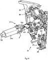
- eine perspektivische Teildarstellung des Entnahmekopfes nach
Fig. 5 beim Entnahmevorgang, d.h. in Verbindung mit dem Aufgabering der Vereinzelungsvorrichtung bei der Entnahme eines Artikels, von der Vereinzelungseinrichtung her gesehen, - Fig. 7
- eine Darstellung des Entnahmekopfes ähnlich derjenigen in
Fig. 6 unter Darstellung der Bereitstellung eines Packmittelstückes zu einem Artikel in dem Entnahmekopf, - Fig. 8
- eine schematische Gesamtdarstellung von Entnahmekopf und Pack- kopf in Vorderansicht,
- Fig. 9
- eine perspektivische, schematische Darstellung einer Antriebseinrich- tung für den Entnahmekopf nach den
Fig. 5 ,6 oder 7 , - Fig. 10
- eine perspektivische Teil-Gesamtdarstellung wesentlicher Funktions-einheiten der Verpakkungsmaschine nach
Fig. 1 , - Fig. 11
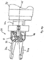
- eine perspektivische, schematische Darstellung eines Teilabschnittes eines Packkopfes in Verbindung mit einem Drehgreifer zur Ansiege- lung des Packmittels an einen Stiel eines Artikels (Lollipop),
- Fig. 12
- eine perspektivische Teilansicht eines hinteren Drehkopfes mit Dreh- greifern in schematischer Darstellung,
- Fig. 13
- eine Drehstation mit vorderem und hinterem Drehkopf unter Ein- schluss des zwischenliegenden Packkopfes in schematischer Darstellung,
- Fig. 14
- eine schematische Darstellung eines vorderen Endes eines beheiz- ten Drehgreifers mit einem Paar Drehgreiferbacken, und
- Fig. 15
- eine schematische Verfahrensdarstellung für den Verpackungsvor- gang in der
Verpakkungsmaschine nach Anspruch 1 für die Verpa- ckung eines Artikels mit Stiel (Lollipop).
- Fig. 1
- a packaging machine for the packaging of articles with stem (lollipops) according to the continuous principle in a schematic front view,
- Fig. 2
- a schematic representation of the article task and -Zcelungseinrichtung,
- Fig. 3
- a schematic partial representation of a brush device for article orientation,
- Fig. 4
- a schematic perspective partial representation of a blank clock sensor device of the article posting and separating device,
- Fig. 5
- a schematic partial view of a removal head and a Aufgaberinges the separating device in the removal of an article in perspective view,
- Fig. 6
- a partial perspective view of the removal head after
Fig. 5 in the removal process, ie in conjunction with the Aufgabering the separating device during the removal of an article, seen from the singulator, - Fig. 7
- a representation of the removal head similar to that in
Fig. 6 depicting the provision of a piece of packaging material to an article in the removal head, - Fig. 8
- a schematic overall view of the removal head and packing head in front view,
- Fig. 9
- a perspective, schematic representation of a drive device for the removal head according to the
Fig. 5 .6 or7 . - Fig. 10
- a perspective partial overall view of essential functional units of Verpakkungsmaschine after
Fig. 1 . - Fig. 11
- a perspective, schematic representation of a partial section of a packing head in conjunction with a rotary gripper for Ansiebling the packaging to a stem of an article (Lollipop),
- Fig. 12
- 3 is a schematic partial perspective view of a rear rotary head with rotary grippers;
- Fig. 13
- a turning station with front and rear turrets including the intermediate packing head in a schematic representation,
- Fig. 14
- a schematic representation of a front end of a heated rotary gripper with a pair of rotary gripper jaws, and
- Fig. 15
- a schematic process diagram for the packaging process in the packaging machine according to
claim 1 for the packaging of an article with a stem (Lollipop).
In
Die Verpackungsmaschine 100 zeichnet sich dadurch aus, dass sie zwischen fertig verpacktem Artikel A und Aufnahme des Artikels A von der Artikel-Aufgabe- und -vereinzelungseinrichtung 1 nur zwei verpackungswesentliche, artikeltragende Köpfe, nämlich den Entnahmekopf 10 und den Packkopf 20 aufweist, wodurch der Verpackungsvorgang wesentlich verdichtet, beschleunigt und effizienter gestaltet werden kann. (Das Abgaberad 50 ist nur eine von dem Verpackungsvorgang unabhängige Hilfseinrichtung). Dabei steigen die Anforderungen an die konstruktive Auslegung der Verpackungsmaschine und insbesondere an die konstruktive Durchbildung des Entnahmekopfes 10. Hierdurch ist es andererseits möglich, wie im vorliegenden Ausführungsbeispiel, Artikel A mit Arbeitsgeschwindigkeiten von z.B. ca. 1.000 Takten pro Minute, d.h. also im Hochleistungsbereich, zu verpacken, wobei im vorliegenden Fall die Artikel A solche sind, die aus einem an einem Stiel A1 befestigten Ball aus Hartkaramell oder anderem Süßstoffmaterial bestehen. In diesem Ausführungsbeispiel wird der Ball des Artikels A mit A2 bezeichnet. In
Auf diese Weise wird ein sehr hoher Füllgrad der Vereinzelungsscheibe 2 erreicht, der zwischen 97% und 100% liegt.In this way, a very high degree of filling of the
Eine äußere Abdeckung 8 sorgt für die Abschirmung der Vereinzelungsscheibe 2 nach außen.An
In den
In
Stromauf einer Entnahmeposition für die Artikel A befindet sich eine Leertakt-Sensoreinrichtung 9, die in vorliegendem Ausführungsbeispiel mittels einer Gabellichtschranke 15 die Stiele A1 der Artikel A abtastet und erfasst, wobei sich stromab der Entnahmeposition eine Ausblaseinrichtung (Ausblasdüse) 16 befindet für Artikel, die ohne Stiel (also nur als Ball) sich in einer der Taschen 4 befinden und nicht weiter verarbeitet werden können. In diesem Bereich ist die Schiene 14 (vgl.
Ein oberhalb des Aufgaberinges 3 und im Bereich oberhalb der Stiele A1 vorgesehener Positionierungsbügel 17 dient ebenfalls der korrekten Positionierung der Artikel A und damit der Positionierungssicherheit. Angesichts der hohen Arbeitsgeschwindigkeiten ist eine möglichst fehlerfreie Orientierung der vereinzelten Artikel A wichtig.A
Das in Verbindung mit den
Im vorliegenden Ausführungsbeispiel ist der Entnahmekopf 10 mit sechs in Umfangsrichtung in gleichmäßigem Winkelabstand angeordneten, schwenkbaren Entnahmeeinheiten 18 versehen (s.
Jede Entnahmeeinheit 18 besteht aus einem Haltebackenpaar 24 mit einer in Drehrichtung des Entnahmekopfes vorauslaufenden, vorderen Haltebacke 24a und einer in Drehrichtung des Entnahmekopfes 10 zurückliegenden, hinteren Haltebacke 24b. Die Haltebacken 24a, 24b jedes Haltebackenpaares 24 sind jeweils auf der gemeinsamen Schwenkachse 19 angeordnet, um die sie einerseits eine Öffnungs- und Schließbewegung zum Erfassen und Halten des Stieles A1 des Artikels A ausführen, wie um diese Schwenkachse 19 auch insgesamt das Haltebackenpaar 24 relativ zur Rotationsbewegung des Entnahmekopfes 10 um die Rotationsachse 11 schwenkbar ist. Dies dient dem Angleichen des Teilungsabstandes der Artikel A in dem Aufgabering 3 an den Teilungsabstand der Entnahmeeinheiten 18 (Haltebackenpaare 24), so dass die Haltebackenpaare 24 sowohl stromauf als auch stromab der Entnahmestelle eine beschleunigte Bewegung ausführen, während eine gleichförmige Bewegung nur in einem Bereich stromauf und stromab einer Übergabestelle, an der die Artikel an den Packkopf 20 übergeben werden, auftritt. Beide Bereiche gehen jeweils ineinander über. Die Haltebacken 24a und 24b weisen, wie deutlich in den
Wesentlich im Hinblick auf die Entnahme der Artikel aus dem Aufgabering 3 durch jeweils ein Haltebackenpaar 24 ist das unmittelbare Erfassen des Stieles in größtmöglicher Nähe zum Ball A2, d.h. unmittelbar an einer zylindrischen Außenfläche des Aufgaberinges 3, wodurch zugleich ein Toleranzausgleich bezüglich der Position des Stieles 1 am Ball A2 gewährleistet ist, da sich Lageabweichungen des Stieles 1 bezüglich des Balles A2 hinsichtlich einer Solllage hier noch wenig oder gar nicht auswirken (anders als am freiliegenden Ende des Stieles A1).Essential with regard to the removal of the articles from the
Selbstverständlich können auch in Abhängigkeit von der Gesamtauslegung der Verpackungsmaschine 100 weniger oder mehr als sechs schwenkbare Entnahmeeinheiten 18 an dem Entnahmekopf 10 vorgesehen sein.Of course, depending on the overall design of the
Neben der Erfassung der Artikel A an den Stielen A1 in einem oberen Endbereich, d.h. in größtmöglicher Nähe zum Ball A2 besteht eine weitere Besonderheit dieses Entnahmekopfes 10 darin, dass er zugleich Packmittelzangen 23 aufweist, d.h. nicht nur der Produktentnahme aus der Artikel-Aufgabe- und -vereinzelungseinrichtung 1 (Vereinzelungsscheibe 2) dient, sondern dem Entnahmekopf 10 bereits das Packmittel, d.h. die Packstoffstücke 12, von einer hier nicht gezeigten Packstoffzuführungsvorrichtung diskret zugeführt werden und damit die Funktionen "Entnahme" und "Packmittelzuführung an den Artikel" in einem Kopf bewirkt werden. Dies ist in
Wie die
Auch diese Packmittelzange 23 führt eine beschleunigte Bewegung aus und dient dazu, die Möglichkeit zu schaffen, bereits zwischen Entnahmestelle am Aufgabering 3 und Übergabestelle zum Packkopf 20 das für die Verpackung des Artikels A benötigte Packstoffstück 12 dem Entnahmekopf 10 zuzuführen und dieses am Artikel A in Verbindung mit der Halterung desselben durch das Haltebackenpaar 24 anzuordnen.This packaging tongs 23 performs an accelerated movement and serves to create the possibility already between sampling point on
Die entsprechenden Steuerbewegungen für jedes Haltebackenpaar 24 als Ganzes, für die Öffnungs- und Schließbewegung der Haltebacken 24a, 24b jedes Haltebackenpaares 24, wie auch die Schwenkbewegung jeder Packmittelzange 23 wird von Steuerkurven abgeleitet, wie sie in Verbindung mit der Rotation des Entnahmekopfes 10 um die stationäre Rotationsachse 11 desselben ausgebildet sind. Hierzu wird auf die schematische, perspektivische Darstellung nach
- Öffnen und Schließen der Haltebackenpaare 24
der Entnahmeeinheiten 18, Schwenken der Haltebackenpaare 24 der Entnahmeeinheiten 18 (insgesamt),- Schwenken bzw. Öffnen und Schließen der Packmittelzangen.
- Opening and closing the holding jaw pairs 24 of the
removal units 18, - Pivoting the holding jaw pairs 24 of the removal units 18 (total),
- Swiveling or opening and closing the packaging tongs.
Wie in
Zusätzlich zu den hinsichtlich des Entnahmekopfes erläuterten Bewegungsabläufen der Haltebakkenpaare 24 können die Haltebackenpaare 24 derselben zusätzlich noch um eine in einer Radialebene verlaufende Hochachse drehbar sein, falls eine Umorientierung der Lage des Produktes, z.B. um 90°, vor der Zuführung des Packstoffstückes erforderlich oder sinnvoll ist. D.h. der Entnahmekopf kann auch zusätzlich noch zu einer Lage-Umorientierung des Artikels zwischen Entnahmeposition von Aufgabering 3 und einer Übergabeposition an dem Packkopf 20 dienen.In addition to the described with respect to the removal head movements of
Vor der Übergabe des Artikels A mit dem Packstoffstück 12 an ein Packkopf-Haltebackenpaar 37 mit den Packkopf-Haltebacken 37a und 37b wird das Packstoffstück winkel- oder U-förmig um den Artikel (d.h. um den Ball A2 desselben) gelegt, wie
In vergleichbarer Weise wie beim Entnahmekopf 10 erfolgt auch im Packkopf 20, der um die stationäre Achse 21 rotiert, die Ableitung aller weiteren Schwenksteuerbewegungen für die Verschwenkung der Packkopf-Haltebacken 37 insgesamt, der Öffnungs- und Schließbewegung der (auf unabhängigen Achsen gelagerten) Packkopf-Haltebacken 37a, 37b, wie auch die Steuerung der Schwenkbewegung der zugehörigen Innenfalter 38 (gleichachsig mit einer Packkopf-Haltebakke 37b eines Packkopf-Haltebackenpaares 37 gelagert) von stationären Steuerkurven, die in Verbindung mit der Rotationsachse 21 vorgesehen sind (ähnlich wie für den Entnahmekopf in
In dem vorliegenden Ausführungsbeispiel soll der Artikel A (Lollipop) einerseits (oben) mit einem Drehflügeleinschlag verpackt sein, während auf der gegenüberliegenden Seite (am Stiel A1) ein sauberes Eindrehen und Ansiegeln des Packstoffes an den Stiel A1 für ein verbraucherfreundliches Produkt unerlässlich ist. Daher ist der Packkopf 20 Teil einer Drehstation 80 mit einem vorderen Drehkopf 60 und einem hinteren Drehkopf 70, wie dies in
Wie aus
Nachfolgend wird daher unter Bezugnahme auf die
Auf der "Stielseite" des Artikels A (Lollipop) ist es erforderlich, das umgebende Ende des Packstoffschlauches sauber an den Stiel A1 und benachbart zu dem artikelseitigen Ende von Stiel A1 und des Balles A2 einzudrehen und anzusiegeln. Hierzu wird ein Drehgreifer 71 verwendet, d.h. eine der Anzahl der Packkopf-Haltebackenpaare 37 entsprechende und synchron mit diesen umlaufende Anzahl von Drehgreifern 71, die am hinteren Drehkopf 70 angeordnet sind und ihrerseits um eine Längsachse 75 relativ zum Drehkopf 70 drehbar sind. Hierfür ist im Drehkopf 70 eine - hier nicht gezeigte - Getriebeanordnung (stationäres Ringrad mit abrollenden Planetenrädern) vorgesehen, so dass die Drehgreifer 71 mit einer gegenüber der Drehzahl des Drehkopfes 70 höheren Drehgeschwindigkeit an diesem vermittels je einer im Drehkopf 70 gelagerten Drehgreiferwelle 75a um ihre Längsachse 75 gleichmäßig rotieren. Die Drehgreifer 71 weisen Drehgreiferbackenpaare 72 mit einer Drehgreiferbacke 72a und einer Drehgreiferbacke 72b auf, die eine Öffnungs- und Schließbewegung um eine zur Längsachse 75 orthogonale Achse F ausführen (Schwenkbewegung). An ihren Innenflächen ist eine Aufnahmeaussparung 73 vorgesehen, bemessen unter Berücksichtigung eines Durchmessers des Stieles A1, der darin aufgenommen wird, um das Packstoffschlauchende zwischen Stiel A1 und Drehgreifer 71 einzudrehen und glatt an den Stiel A1 anzusiegeln, wobei die Drehgreifer 71 um ihre Längsachse 75 die vorerläuterte Rotationsbewegung relativ zum Drehkopf 70 ausführen. Die Drehgreiferbacken 72a, 72b sind gegenüber ihres Lagerungsabschnittes um die Achse F um ca. 90° gekröpft, so dass der Stiel A1 der Produkte beständig glatt und mit entsprechendem Spiel zum Ansiegeln des Packstoffes umgriffen werden kann.On the "stick side" of the article A (lollipop), it is necessary to cleanly screw in and seal the surrounding end of the packaging tube to the stem A1 and adjacent to the article-side end of the stem A1 and the ball A2. For this purpose, a
Die Drehgreifer 71 zeichnen sich gegenüber den Drehgreifern 61 am vorderen Drehkopf 60 dadurch aus, dass sie beheizt sind, und durch die Beheizung des Drehgreifers 31 bzw. zumindest einer der Drehgreiferbacken 72a, 72b kann ein Heißsiegeln und in Verbindung mit entsprechendem Packmaterial eine hohe Ansiegelqualität am Stiel im Bereich des Überganges vom Stiel A1 zum Ball A2 realisiert werden.The
Wie die perspektivische Teilansicht des hinteren Drehkopfes 70 gemäß
Durch Veränderung von Druck und Temperatur an den Drehgreiferpaaren 71 kann die Siegelfestigkeit und damit das Öffnungsverhalten der Verpackung positiv beeinflusst werden.By changing the pressure and temperature on the rotary gripper pairs 71, the seal strength and thus the opening behavior of the packaging can be positively influenced.
In Verbindung mit den Drehgreiferbacken 72a, 72b ist eine vorzugsweise berührungslose Temperaturmessung (Infrarot-Temperaturmessung) vorgesehen, die Teil eines Steuerkreises zur Regelung der Heizleistung zu den Drehgreiferbackenpaaren ist. Auf diese Weise kann eine genaue Temperaturführung unter Berücksichtigung der Materialeigenschaften des Packstoffmateriales und sonstiger Produktgegebenheiten erreicht werden. Die Verwendung beheizter Drehgreifer zum Ansiegeln des Packstoffes ermöglicht auch die Verwendung stärkerer oder eine größere Rückstellkraft aufweisender Verpackungsfolien.In connection with the
Die Temperaturüberwachung bzw. -messung könnte auch unmittelbar über Temperaturfühler in den beheizten Teilen der Drehgreifer 71 erfolgen. Die Anwendung beheizter Drehgreifer 71 ist nicht auf das vorliegende Ausführungsbeispiel oder Produkte mit Stiel begrenzt, sondern auch für andere Anwendungen geeignet, z.B. bei der Herstellung von Drehflügelverpackungen bzw. Verpackungen im Doppeldreheinschlag oder Einfach-Dreheinschlag (Säckchenfaltung, Bunch-Faltung), insbesondere bei der Verwendung von verhältnismäßig starken bzw. eine hohe Rückstellkraft aufweisenden Verpackungsmaterialien.The temperature monitoring or measurement could also be done directly via temperature sensor in the heated parts of the
Wie bereits in Verbindung mit
Die Abgabeeinrichtung, die die fertig verpackten Artikel (Lollipops) über ein Abgaberad 50 an ein Abgabeband 40 wegfördert, ist schematisch in
In
Mit der vorliegenden Erfindung wird erstmals eine kontinuierlich arbeitende Verpackungsmaschine vorgeschlagen, die nur zwei verpackungswesentliche, produkttragende Köpfe, den Entnahmekopf und den Packkopf aufweist und deren Entnahmekopf mit zusätzlichen Funktionsorganen zur Packmittelbereitstellung versehen ist.With the present invention, a continuously operating packaging machine is proposed for the first time, which has only two packaging-essential, product-carrying heads, the removal head and the packing head and the removal head is provided with additional functional organs for supplying packaging.
Wenn auch besonders hierfür geeignet, ist die Erfindung nicht auf die Verpackung von Süßwaren mit Stiel beschränkt, sondern es kann unter entsprechender Anpassung der vorstehend dargelegten Grundsätze auf vergleichbare Weise auch die Verpackung anderer kleinstückiger Artikel in anderen Faltungsarten erfolgen. Bei der Verpackung von Artikeln mit Stiel ist es durch das Ergreifen der Artikel am Stiel in einem Stielabschnitt möglichst nahe am eigentlichen Produkt (Ball) erstmals gelungen, den Einfluss von aus der Produktherstellung (Anbringung des Stieles am Ball) resultierende Fehler und Toleranzen praktisch in ihrem Einfluss auf den weiteren Verpackungsvorgang praktisch zu eliminieren. Die Verwendung beheizter Drehgreifer ermöglicht nicht nur ein sauberes Ansiegeln von Verpackungsmaterial an einem Stiel, sondern grundsätzlich eine Verbesserung der Herstellung von Verpackungen mit Drehflügeln.Although particularly suitable for this purpose, the invention is not limited to the packaging of confectionery with stem, but it can under appropriate Adapting the principles set out above in a similar way, the packaging of other small-sized articles in other types of folding done. When packing articles with a handle, by grasping the articles on a stick in a section of stem as close as possible to the actual product (ball), the influence of errors and tolerances resulting from product production (attachment of the stem to the ball) is practically achieved Virtually eliminate influence on the further packaging process. The use of heated rotary grippers enables not only a clean sealing of packaging material on a stick, but in principle an improvement in the manufacture of packages with rotary blades.
Insgesamt besitzt eine Verpackungsmaschine nach der vorliegenden Erfindung einen gedrängten, kompakten Aufbau und zeichnet sich durch eine für komplizierte Produkte, wie es Produkte mit Stiel sind, bisher unerreichte Verpackungsleistung in einem Bereich von 600 bis 1000 Arbeitstakten pro Minute aus, bei zugleich dynamisch ruhigem Lauf, letzteres, insbesondere aufgrund des kontinuierlichen Arbeitsprinzips.Overall, a packaging machine according to the present invention has a compact, compact structure and is characterized by a for complicated products, such as products with stem, previously unattained packaging performance in a range of 600 to 1000 strokes per minute, at the same time dynamic quiet running, the latter, in particular because of the continuous working principle.
Neben einem niedrigen Geräuschpegel wird aufgrund geringer dynamischer Beanspruchung und auch des gewählten Verpackungsprinzips (Einschießen des Packstoffes bereits in den Entnahmekopf) eine hohe Produktschonung und geringe Packmittelbeanspruchung erreicht. Der maschinentechnische Verschleiß und Wartungsaufwand sind daher gering, die Effizienz und Einsatzfähigkeit der Verpackungsmaschine entsprechend hoch.In addition to a low noise level, high product protection and low packaging material stress are achieved due to low dynamic stress and also the chosen packaging principle (injection of the packaging material already into the removal head). The mechanical wear and maintenance costs are therefore low, the efficiency and operational capability of the packaging machine correspondingly high.
Durch die Erfindung wird erstmals eine nach dem kontinuierlichen Prinzip arbeitende Verpackungsmaschine mit zwei produktverarbeitenden Köpfen geschaffen, die es ermöglicht, bei komplizierten Produkten (Produkten mit Stiel) in bisher nicht erreichbarer Leistungsbereiche von z.B. ca. 1.000 Arbeitstakten pro Minute vorzudringen, dabei einen kompakten und produkt- und verpackungsschonenden Aufbau zu realisieren, verbunden mit hoher Produktsicherheit und geringer Störanfälligkeit der Verpackungsvorrichtung.The invention provides, for the first time, a continuous product packaging machine with two product-processing heads, which makes it possible, in the case of complicated products (products with handle), in previously unachievable performance ranges of e.g. Approximately 1,000 work cycles per minute to penetrate, while a compact and product and packaging sparing structure to realize, combined with high product safety and low susceptibility to failure of the packaging device.
Claims (15)
- Method for the continuous packaging of small articles (A), in particular articles (A) with a stick (A1), in the high performance range of, for example, 1000 operating cycles per minute,
whereby the articles (A) are distributed essentially in a horizontal positioning plane by an article feeding and distributing device (1), and the articles (A) are individually accepted in a rotary motion by a pick-up head (10), rotatable about a stationary axis of rotation (11) and arranged above the article feeding and distributing device (1), by opposed movable holding jaws (24a, 24b) of pairs of holding jaws (24) which are pivotable as pick-up units (18) about separate pivot axes (19) extending parallel to the rotation axis (11) of the pick-up head (10), on the pick-up head (10) and are located to circulate with it, and said articles are transported continuously to a packing head (20) which acts to form the packaging completely,
whereby the packing head (20) is also arranged above the article feeding and distributing device (1) and is rotatable about a stationary axis of rotation (21), the articles are guided in the pick-up head (10) on a first circular track section running essentially in a vertical plane, and packaging material is fed essentially radially to the motion of the article (A) towards it and clamped near the article (A), which is held by an associated pair of holding jaws (24), by a packing material tongs (23) and a clamping counterpart (35) on the associated pair of holding jaws (24), wherein the packing material tongs (23) are pivoted about a tong pivot axis (22) rotating with the pick-up head (10) and being parallel to the pivot axis (19) of the associated pick-up unit (18). - Method in accordance with claim 1, characterised in that the packaging material is inserted into the pick-up head (10).
- Method in accordance with claim 1 or 2, characterised in that a piece of packaging material (12) is placed in an angular or U shape around the article (A) in the pick-up head (10), and / or packing head holding jaws (37a, 37b) of a pair of packing head holding jaws (37) grasp the article (A) as the piece of packaging material (12) is placed in an intermediate position, in particular to form a packaging material tube.
- Method in accordance with at least one of the foregoing claims 1 to 3, characterised in that the packing material tongs (23) provided to attach a piece of packaging material (12) to the associated article (A) are accelerated before the packaging material is fed into the pick-up head (10).
- Method in accordance with at least one of the foregoing claims 1 to 4, characterised in that, on the path between acceptance of the article (A) from the article feeding and distributing device (1) by the pick-up head (10) and the delivery of the article (A) from the pick-up head (10) to the packing head (20), the orientation of the position of the article (A) is changed, in particular by rotating the article (A) by approx. 90°, and / or the article (A) is guided also by the packing head (20) on a second circular track section running essentially in a vertical plane.
- Method in accordance with at least one of the foregoing claims 1 to 5, characterised in that the distributed articles (A) are provided by the article feeding and distributing device (1) by a rotating motion in a counter clockwise direction, and / or the packing head (20) is driven in a counter clockwise direction to cooperate with the pick-up head (10) driven in a clockwise direction.
- Method in accordance with at least one of the foregoing claims 1 to 6, characterised by- acceptance from above of a distributed article (A) by a pair of holding jaws (24) pivotable on the pick-up head (10) about a pivot axis (19) and a rotational motion of the article (A) in a clockwise direction by the pick-up head (10),- radial feed of the packaging material into the pick-up head (10) between pick-up of the article (A) from the article feeding and distributing device (1) and delivery of the article (A) to the packing head (20),- the placing of a piece of packaging material (12) near the article (A) in the pick-up head (10) while pivoting the packing material tongs (21), allocated to the pick-up unit (18) of the pick-up head (10), about its curve-controlled driven tong pivot axis (22) fixed in the pick-up head (10) and extending parallel to the axis of rotation (11) of the pick-up head (10) and of the pivot axis (19) of the pick-up units (18), and- complete forming of the packaging of the article (A) by the packing head (20) which rotates in a counter clockwise direction and acceptance of the articles (A) by packing head holding jaws (37a, 37b) located to pivot on the packing head (20).
- Method in accordance with at least one of the foregoing claims 1 to 7, characterised in that a difference in separation between the distributed articles (A) in the article feeding and distributing device (1) and the pick-up units (18) of the pick-up head (10) accepting the articles (A) is compensated by an accelerated motion of the pick-up units (18) provided before and/or after acceptance of the article (A), in particular a pivoting motion about the pivot axis (19) of each pick-up unit.
- Device for the packaging of small articles, in particular articles with a stick, with only two rotating heads carrying articles, whereby, arranged above an article feeding and distributing device (1), are a pick-up head (10) rotatable about a stationary axis of rotation (11) and a packing head (20) rotatable about a stationary axis of rotation (21) which is in rolling engagement with said pick-up head,
the pick-up head (10) is provided with pick-up units (18) which comprise opposed movable holding jaws (24a, 24b) of pairs of holding jaws (24), whereby the pick-up units (18) are provided to pivot about separate pivot axes (19) extending parallel to the axis of rotation (11) of the pick-up head (10), on the pick-up head (10),
packaging material is fed essentially radially to the motion of the article (A) in the pick-up head (10) to said head, and each pick-up unit (18) with the pairs of holding jaws (24) has assigned thereto a set of packing material tongs (23) which are pivotable about a tong pivot axis (22) which is fixed in the pick-up head (10) and parallel to the pivot axis (19) of the associated pick-up unit (18) and which are used for clamping the piece of the packaging material (12) near the article (A) held by the associated pair of holding jaws (24) between the packing material tongs (23) and a clamping counterpart (35) on the associated pair of holding jaws (24). - Device in accordance with claim 9, characterised in that the packing material tongs (23) consist of a sheet which is pivotable about the tong pivot axis (22) parallel to the pivot axis (19) of the pick-up units and the axis of rotation (11) of the pick-up head (10), and the tong pivot axis (22) is provided separate from the pivot axis (19) of the pick-up units (18) and can be controlled independently of the latter, preferably the packing material tongs can be controlled to perform an accelerated motion.
- Device in accordance with at least one of the foregoing claims 9 or 10, characterised in that the pivotable pick-up units (18) with the pairs of holding jaws (24) are provided with equiangular spacing on the pick-up head (10) and circulate around with it.
- Device in accordance with at least one of the foregoing claims 9 to 11, characterised in that, in conjunction with the rotation of the pick-up head (10) about the stationary axis of rotation (11), control movements are provided en bloc for each pair of holding jaws (24) for the opening and closing motion of the holding jaws (24a, 24b) of each pair of holding jaws (24) as well as the pivotal motion of each packing material tongs (23) derived from stationary control cams (25, 26, 31) in conjunction with control rollers (27, 28) which provide control of the motion of the pivot axes (19) fixed in the pick-up head (10) and of the tong pivot axes (22).
- Device in accordance with at least one of the foregoing claims 9 to 12, characterised in that the pivot axes (19) of the pick-up units (18) and the tong pivot axes (22) of the packing material tongs (23) allocated to the latter are fixed stationary and rotatable In the pick-up head (10) and rotate with said head, and are rotatable during the rotation of the pick-up head (10) by control rollers (27, 28) or cam followers engaging with stationary control cams (25, 26, 31).
- Device in accordance with at least one of the foregoing claims 9 to 13, characterised in that the articles (A) are guided on the packing head as they rotate through approx. 270° until completely packed.
- Device in accordance with at least one of the foregoing claims 9 to 14, characterised in that a packing material feeding device is provided adjacent to the pick-up head (10), the packaging material is inserted into the pick-up head (10), and a motion control to- open and close the pairs of holding jaws (24) of the pick-up units (18),- pivot the pairs of holding jaws (24) of the pick-up units (18) en bloc,- pivot the packing material tongs (23)is provided in the pick-up head (10).
Applications Claiming Priority (3)
| Application Number | Priority Date | Filing Date | Title |
|---|---|---|---|
| DE200510017329 DE102005017329B4 (en) | 2005-04-14 | 2005-04-14 | Method and device for packaging small-sized articles |
| EP08005994A EP1939093B1 (en) | 2005-04-14 | 2006-02-27 | Method and device for packaging small articles |
| EP20060003941 EP1712472B1 (en) | 2005-04-14 | 2006-02-27 | Method and device for packaging small products |
Related Parent Applications (4)
| Application Number | Title | Priority Date | Filing Date |
|---|---|---|---|
| EP20060003941 Division EP1712472B1 (en) | 2005-04-14 | 2006-02-27 | Method and device for packaging small products |
| EP08005994A Division EP1939093B1 (en) | 2005-04-14 | 2006-02-27 | Method and device for packaging small articles |
| EP06003941.9 Division | 2006-02-27 | ||
| EP08005994.2 Division | 2008-03-28 |
Publications (3)
| Publication Number | Publication Date |
|---|---|
| EP2210813A1 EP2210813A1 (en) | 2010-07-28 |
| EP2210813B1 EP2210813B1 (en) | 2012-11-14 |
| EP2210813B2 true EP2210813B2 (en) | 2017-03-08 |
Family
ID=36283903
Family Applications (5)
| Application Number | Title | Priority Date | Filing Date |
|---|---|---|---|
| EP20060003941 Revoked EP1712472B1 (en) | 2005-04-14 | 2006-02-27 | Method and device for packaging small products |
| EP10004982.4A Active EP2218645B1 (en) | 2005-04-14 | 2006-02-27 | Method and device for packaging small articles |
| EP10004445.2A Not-in-force EP2210813B2 (en) | 2005-04-14 | 2006-02-27 | Method and device for packaging small articles |
| EP08005994A Expired - Fee Related EP1939093B1 (en) | 2005-04-14 | 2006-02-27 | Method and device for packaging small articles |
| EP08005993A Expired - Fee Related EP1939092B1 (en) | 2005-04-14 | 2006-02-27 | Method and device for packaging small articles |
Family Applications Before (2)
| Application Number | Title | Priority Date | Filing Date |
|---|---|---|---|
| EP20060003941 Revoked EP1712472B1 (en) | 2005-04-14 | 2006-02-27 | Method and device for packaging small products |
| EP10004982.4A Active EP2218645B1 (en) | 2005-04-14 | 2006-02-27 | Method and device for packaging small articles |
Family Applications After (2)
| Application Number | Title | Priority Date | Filing Date |
|---|---|---|---|
| EP08005994A Expired - Fee Related EP1939093B1 (en) | 2005-04-14 | 2006-02-27 | Method and device for packaging small articles |
| EP08005993A Expired - Fee Related EP1939092B1 (en) | 2005-04-14 | 2006-02-27 | Method and device for packaging small articles |
Country Status (3)
| Country | Link |
|---|---|
| EP (5) | EP1712472B1 (en) |
| DE (4) | DE102005017329B4 (en) |
| ES (5) | ES2341190T3 (en) |
Families Citing this family (19)
| Publication number | Priority date | Publication date | Assignee | Title |
|---|---|---|---|---|
| DE602006006651D1 (en) † | 2006-04-20 | 2009-06-18 | Cfs Weert Bv | Device for separating lollipops |
| DE202006020630U1 (en) * | 2006-05-03 | 2009-04-02 | Robert Bosch Gmbh | Machine for packaging small-sized confectionery |
| DE102008018224A1 (en) | 2008-04-10 | 2009-10-15 | Theegarten-Pactec Gmbh & Co. Kg | Method and device for transferring small-sized, in particular provided with a stem products to a longitudinal conveyor |
| DE102008019605A1 (en) * | 2008-04-18 | 2009-10-22 | Theegarten Pactec Gmbh & Co. Kg | Process for packaging small-sized articles, in particular chocolate-coated pralines or caramels, in a continuous mode of operation and packaging machine, in particular for carrying out the method |
| CN102219056B (en) * | 2011-04-19 | 2012-12-26 | 北京申晨机械设备有限公司 | Tip-pinching packaging machine and method of tip-pinching package by using same |
| DE102011122542A1 (en) * | 2011-12-27 | 2013-06-27 | Theegarten-Pactec Gmbh & Co. Kg | Packaging machine for packaging small-sized products and separating device |
| DE102012019909A1 (en) | 2012-10-11 | 2014-04-17 | Theegarten-Pactec Gmbh & Co. Kg | High-performance packaging method for packaging, in particular small-sized, products and high-performance packaging device, in particular for carrying out the method |
| DE102014005959A1 (en) | 2013-04-30 | 2014-10-30 | Theegarten-Pactec Gmbh & Co. Kg | Method for grouping articles into article poles and grouping device and packaging machine with such articles and control device for product holding devices |
| DE102013007385A1 (en) | 2013-04-30 | 2014-10-30 | Theegarten-Pactec Gmbh & Co. Kg | Control device for product holding devices and packaging machine with such |
| EP2894103B1 (en) | 2014-01-10 | 2016-09-07 | Robert Bosch Gmbh | Method and device for packaging food products into individual portions |
| CN104176294A (en) * | 2014-08-29 | 2014-12-03 | 成都三可实业有限公司 | Candy inner paper packaging device |
| CN105346755B (en) * | 2015-11-30 | 2018-11-20 | 成都三可实业有限公司 | A kind of lollipop packing machine |
| ES2660447T3 (en) | 2015-12-29 | 2018-03-22 | Theegarten-Pactec Gmbh & Co. Kg | Procedure and device for packaging small items |
| DE102017206867A1 (en) | 2017-04-24 | 2018-10-25 | Theegarten-Pactec Gmbh & Co. Kg | Rotary head and method of transporting products using the same |
| CN109573146B (en) * | 2018-11-30 | 2023-07-28 | 江苏飞龙食品机械有限公司 | Single-torsion air-blowing packaging machine |
| CN111330923B (en) * | 2020-03-11 | 2021-05-04 | 新昌县兴欧智能科技有限公司 | Double-end formula lollipop equipment for packing of kinking |
| CN116829483A (en) * | 2021-01-12 | 2023-09-29 | Gea食品策划韦尔特公司 | Servo-driven selecting device |
| CN113602569A (en) * | 2021-08-10 | 2021-11-05 | 上海理工大学 | Full-automatic vertical packaging machine for barrel-made products |
| CN115593699B (en) * | 2022-12-15 | 2023-02-28 | 常州市双马医疗器材有限公司 | Packaging equipment for syringe production |
Citations (12)
| Publication number | Priority date | Publication date | Assignee | Title |
|---|---|---|---|---|
| DE606423C (en) † | 1933-03-15 | 1934-12-01 | Bruno Boerner | Machine for packing bulk items |
| DE2416656A1 (en) † | 1973-04-07 | 1974-10-17 | Tenchi Kikai Kk | DEVICE FOR INDEPENDENT PACKAGING AND ALIGNMENT OF PIECES OF SWEET GOODS |
| DE3049590A1 (en) † | 1980-02-14 | 1981-09-24 | Baker Perkins Holdings Ltd., Peterborough, Cambridgeshire | PACKING DEVICE FOR SWEETS |
| DE3324984A1 (en) † | 1982-09-30 | 1984-04-05 | Veb Kombinat Nagema, Ddr 8045 Dresden | DEVICE FOR WRAPPING SWEETS |
| DE3713332A1 (en) † | 1986-06-04 | 1987-12-23 | Nagema Veb K | DEVICE FOR DELIVERING SWEETS |
| DE4314142C1 (en) † | 1993-05-01 | 1994-07-28 | Pactec Dresden Gmbh | Device for folding a packaging envelope for folding bags or cups |
| DE19502562A1 (en) † | 1995-01-27 | 1996-08-01 | Pactec Verpackungsmaschinen Fa | Continuous system for wrapping goods in sheet material |
| DE19618510A1 (en) † | 1996-05-08 | 1997-11-13 | Pactec Verpackungsmaschinen Fa | Rotary transport device for use in packing machine |
| DE19642014A1 (en) † | 1996-10-11 | 1998-04-16 | Pactec Verpackungsmaschinen Fa | Device for packaging small items in the fold wrapper |
| DE19715949A1 (en) † | 1997-04-16 | 1998-10-22 | Pactec Verpackungsmaschinen Fa | Process for separating small-sized objects and separating device |
| DE19920710A1 (en) † | 1999-05-05 | 2000-11-09 | Pactec Verpackungsmaschinen Fa | Individual wrapping machine for candies is capable of high number of different folding operations using rotating release head and rotating packing head with movable folding action units |
| DE10217898A1 (en) † | 2002-04-22 | 2003-11-06 | Theegarten Pactec Gmbh & Co Kg | Device and method for separating small items |
Family Cites Families (15)
| Publication number | Priority date | Publication date | Assignee | Title |
|---|---|---|---|---|
| JPS5215030B2 (en) * | 1971-11-09 | 1977-04-26 | ||
| EP0036282A1 (en) * | 1980-03-13 | 1981-09-23 | Wm. Wrigley Jr. Company | Machine for wrapping articles |
| DE3171685D1 (en) * | 1981-05-13 | 1985-09-12 | Derckx Henricus A J M | A device for twisting a packing wrapping |
| IT1234027B (en) * | 1989-03-14 | 1992-04-24 | Gd Spa | CONTINUOUS WRAPPING MACHINE |
| US5450706A (en) * | 1993-05-24 | 1995-09-19 | Latini Machine Company, Inc. | Single twist bunch wrapping machine |
| NL9402167A (en) * | 1994-12-20 | 1996-08-01 | Derckx Henricus A J M | Device for packing a lolly. |
| AU9442598A (en) * | 1998-10-15 | 2000-05-01 | Carugil, S.L. | Machine for wrapping lollipops |
| US6539687B1 (en) * | 2000-07-13 | 2003-04-01 | Mars, Incorporated | Modular wrapping apparatus |
| ITMI20011736A1 (en) * | 2001-08-07 | 2003-02-07 | Eurosicma S P A | ORDERED FEEDING MACHINE FOR SWEET PRODUCTS |
| BR0309351B1 (en) * | 2002-04-18 | 2012-09-18 | machine for packing products. | |
| DE10217892A1 (en) * | 2002-04-22 | 2003-11-06 | Theegarten Pactec Gmbh & Co Kg | Device and method for feeding packaging material |
| NL1023733C2 (en) * | 2003-06-24 | 2004-12-28 | C F S Weert B V | Packing machine. |
| NL1028314C2 (en) * | 2004-07-26 | 2006-04-04 | Cfs Weert Bv | Lolly and device for its manufacture. |
| NL1026780C2 (en) * | 2004-08-04 | 2006-02-13 | Cfs Weert Bv | Transfer device for lollipops. |
| NL1026777C2 (en) * | 2004-08-04 | 2006-02-13 | Cfs Weert Bv | Packing machine for lollipops. |
-
2005
- 2005-04-14 DE DE200510017329 patent/DE102005017329B4/en not_active Expired - Fee Related
-
2006
- 2006-02-27 EP EP20060003941 patent/EP1712472B1/en not_active Revoked
- 2006-02-27 EP EP10004982.4A patent/EP2218645B1/en active Active
- 2006-02-27 ES ES08005993T patent/ES2341190T3/en active Active
- 2006-02-27 EP EP10004445.2A patent/EP2210813B2/en not_active Not-in-force
- 2006-02-27 ES ES08005994T patent/ES2340635T3/en active Active
- 2006-02-27 EP EP08005994A patent/EP1939093B1/en not_active Expired - Fee Related
- 2006-02-27 DE DE200650006945 patent/DE502006006945D1/en active Active
- 2006-02-27 DE DE200650001468 patent/DE502006001468D1/en active Active
- 2006-02-27 ES ES10004982.4T patent/ES2695033T3/en active Active
- 2006-02-27 DE DE200650006868 patent/DE502006006868D1/en active Active
- 2006-02-27 ES ES10004445.2T patent/ES2393705T5/en active Active
- 2006-02-27 ES ES06003941T patent/ES2309845T3/en active Active
- 2006-02-27 EP EP08005993A patent/EP1939092B1/en not_active Expired - Fee Related
Patent Citations (12)
| Publication number | Priority date | Publication date | Assignee | Title |
|---|---|---|---|---|
| DE606423C (en) † | 1933-03-15 | 1934-12-01 | Bruno Boerner | Machine for packing bulk items |
| DE2416656A1 (en) † | 1973-04-07 | 1974-10-17 | Tenchi Kikai Kk | DEVICE FOR INDEPENDENT PACKAGING AND ALIGNMENT OF PIECES OF SWEET GOODS |
| DE3049590A1 (en) † | 1980-02-14 | 1981-09-24 | Baker Perkins Holdings Ltd., Peterborough, Cambridgeshire | PACKING DEVICE FOR SWEETS |
| DE3324984A1 (en) † | 1982-09-30 | 1984-04-05 | Veb Kombinat Nagema, Ddr 8045 Dresden | DEVICE FOR WRAPPING SWEETS |
| DE3713332A1 (en) † | 1986-06-04 | 1987-12-23 | Nagema Veb K | DEVICE FOR DELIVERING SWEETS |
| DE4314142C1 (en) † | 1993-05-01 | 1994-07-28 | Pactec Dresden Gmbh | Device for folding a packaging envelope for folding bags or cups |
| DE19502562A1 (en) † | 1995-01-27 | 1996-08-01 | Pactec Verpackungsmaschinen Fa | Continuous system for wrapping goods in sheet material |
| DE19618510A1 (en) † | 1996-05-08 | 1997-11-13 | Pactec Verpackungsmaschinen Fa | Rotary transport device for use in packing machine |
| DE19642014A1 (en) † | 1996-10-11 | 1998-04-16 | Pactec Verpackungsmaschinen Fa | Device for packaging small items in the fold wrapper |
| DE19715949A1 (en) † | 1997-04-16 | 1998-10-22 | Pactec Verpackungsmaschinen Fa | Process for separating small-sized objects and separating device |
| DE19920710A1 (en) † | 1999-05-05 | 2000-11-09 | Pactec Verpackungsmaschinen Fa | Individual wrapping machine for candies is capable of high number of different folding operations using rotating release head and rotating packing head with movable folding action units |
| DE10217898A1 (en) † | 2002-04-22 | 2003-11-06 | Theegarten Pactec Gmbh & Co Kg | Device and method for separating small items |
Non-Patent Citations (1)
| Title |
|---|
| "Silesia Confiserie Manual No.3", 1983, article A. MEINERS, K. KREITEN, H. JOIKE: "Das neue Handbuch der Süßwarenindustrie" † |
Also Published As
| Publication number | Publication date |
|---|---|
| ES2393705T5 (en) | 2017-07-31 |
| EP1939092A3 (en) | 2008-07-09 |
| DE502006006868D1 (en) | 2010-06-10 |
| ES2309845T3 (en) | 2008-12-16 |
| ES2695033T3 (en) | 2018-12-28 |
| EP1939093A3 (en) | 2008-07-09 |
| EP1939093B1 (en) | 2010-04-28 |
| EP1939092A2 (en) | 2008-07-02 |
| ES2393705T3 (en) | 2012-12-27 |
| EP1939092B1 (en) | 2010-05-12 |
| DE502006006945D1 (en) | 2010-06-24 |
| EP2210813A1 (en) | 2010-07-28 |
| EP1712472B1 (en) | 2008-09-03 |
| DE102005017329B4 (en) | 2014-10-16 |
| ES2341190T3 (en) | 2010-06-16 |
| EP1712472A1 (en) | 2006-10-18 |
| EP1939093A2 (en) | 2008-07-02 |
| EP2210813B1 (en) | 2012-11-14 |
| EP2218645A1 (en) | 2010-08-18 |
| DE102005017329A1 (en) | 2006-10-19 |
| ES2340635T3 (en) | 2010-06-07 |
| EP2218645B1 (en) | 2018-10-31 |
| DE502006001468D1 (en) | 2008-10-16 |
Similar Documents
| Publication | Publication Date | Title |
|---|---|---|
| EP2210813B2 (en) | Method and device for packaging small articles | |
| EP0034377B2 (en) | Method and apparatus for feeding articles, especially packages, into the run of an endless conveyor | |
| DE2526047A1 (en) | REVOLVING CONVEYOR ON A WRAPPING MACHINE | |
| EP0275481B1 (en) | Method and device for packaging paper handkerchiefs | |
| DE3545884A1 (en) | DEVICE FOR PRODUCING (CIGARETTE) PACKS FROM AT LEAST ONE FOLDABLE CUT | |
| DE102014005959A1 (en) | Method for grouping articles into article poles and grouping device and packaging machine with such articles and control device for product holding devices | |
| EP2108589B1 (en) | Method and device for transferring small products on a longitudinal transport device, especially those with a handle | |
| EP2282942A2 (en) | Method for the packaging of small articles and modular packaging machine for carrying out the method | |
| DE3915888C2 (en) | Device for transferring sweets | |
| EP0806358B1 (en) | Method and device for transferring articles | |
| DE2454743A1 (en) | DEVICE FOR PACKAGING MACHINES TO SHAPE SWEETS AND THE DGL. TO DESIGN IN THE PACKAGING WITH ONE (BASKET) OR TWO SO-CALLED ZIPFELS | |
| DE60310904T2 (en) | wrapping | |
| EP0835831B1 (en) | Rotary transport device for transferring articles | |
| DE202005021491U1 (en) | packaging machine | |
| DE2329534C3 (en) | Device for the continuous wrapping of sweets or similar small parts | |
| EP2522604A1 (en) | Method for transfer of small sized products and removal device and packaging machine with such a removal device | |
| EP0806385A1 (en) | Method and transfer device for delivering groups of articles from a stacking belt conveyor | |
| EP1357066B1 (en) | Device and method for receiving and transferring articles | |
| CH556767A (en) | Tea-bag collective packing system - wheel with cam controlled jaw pockets collects, clamps and discharges package | |
| DE19860863A1 (en) | Packing of small shaped individual pieces to sticks contg. several individual tested for individual faults and non-faulty individual pieces only assembled to stack and passed to stick packing unit and are packed to form stick | |
| DE2454772A1 (en) | HIGH PERFORMANCE PACKAGING MACHINE FOR SWEETS AND DGL. IN IMPROVED DESIGN FOR THE MANUFACTURING OF THE TUBULAR PACKAGING PART, THE TURNED END SECTION OF WHICH ENDS ON THE WIDE SIDE OF THE ARTICLE TO BE PACKED | |
| EP1016594A2 (en) | Method and apparatus for packaging individual articles in stacks containing several individual articles |
Legal Events
| Date | Code | Title | Description |
|---|---|---|---|
| PUAI | Public reference made under article 153(3) epc to a published international application that has entered the european phase |
Free format text: ORIGINAL CODE: 0009012 |
|
| AC | Divisional application: reference to earlier application |
Ref document number: 1712472 Country of ref document: EP Kind code of ref document: P Ref document number: 1939093 Country of ref document: EP Kind code of ref document: P |
|
| AK | Designated contracting states |
Kind code of ref document: A1 Designated state(s): CH DE ES GB IT LI NL |
|
| 17P | Request for examination filed |
Effective date: 20110124 |
|
| GRAP | Despatch of communication of intention to grant a patent |
Free format text: ORIGINAL CODE: EPIDOSNIGR1 |
|
| GRAJ | Information related to disapproval of communication of intention to grant by the applicant or resumption of examination proceedings by the epo deleted |
Free format text: ORIGINAL CODE: EPIDOSDIGR1 |
|
| RIC1 | Information provided on ipc code assigned before grant |
Ipc: B65B 11/34 20060101ALN20120621BHEP Ipc: B65B 25/00 20060101AFI20120621BHEP |
|
| RIC1 | Information provided on ipc code assigned before grant |
Ipc: B65B 11/34 20060101ALN20120625BHEP Ipc: B65B 25/00 20060101AFI20120625BHEP |
|
| RIC1 | Information provided on ipc code assigned before grant |
Ipc: B65B 25/00 20060101AFI20120718BHEP Ipc: B65B 11/34 20060101ALN20120718BHEP |
|
| GRAP | Despatch of communication of intention to grant a patent |
Free format text: ORIGINAL CODE: EPIDOSNIGR1 |
|
| RIC1 | Information provided on ipc code assigned before grant |
Ipc: B65B 11/34 20060101ALN20120815BHEP Ipc: B65B 25/00 20060101AFI20120815BHEP |
|
| GRAS | Grant fee paid |
Free format text: ORIGINAL CODE: EPIDOSNIGR3 |
|
| GRAA | (expected) grant |
Free format text: ORIGINAL CODE: 0009210 |
|
| AC | Divisional application: reference to earlier application |
Ref document number: 1712472 Country of ref document: EP Kind code of ref document: P Ref document number: 1939093 Country of ref document: EP Kind code of ref document: P |
|
| AK | Designated contracting states |
Kind code of ref document: B1 Designated state(s): CH DE ES GB IT LI NL |
|
| REG | Reference to a national code |
Ref country code: GB Ref legal event code: FG4D Free format text: NOT ENGLISH |
|
| REG | Reference to a national code |
Ref country code: CH Ref legal event code: EP |
|
| REG | Reference to a national code |
Ref country code: ES Ref legal event code: FG2A Ref document number: 2393705 Country of ref document: ES Kind code of ref document: T3 Effective date: 20121227 |
|
| REG | Reference to a national code |
Ref country code: DE Ref legal event code: R096 Ref document number: 502006012227 Country of ref document: DE Effective date: 20130110 |
|
| REG | Reference to a national code |
Ref country code: CH Ref legal event code: NV Representative=s name: REUTELER AND CIE S.A., CH |
|
| REG | Reference to a national code |
Ref country code: NL Ref legal event code: T3 |
|
| PLBI | Opposition filed |
Free format text: ORIGINAL CODE: 0009260 |
|
| PLAX | Notice of opposition and request to file observation + time limit sent |
Free format text: ORIGINAL CODE: EPIDOSNOBS2 |
|
| 26 | Opposition filed |
Opponent name: ROBERT BOSCH GMBH Effective date: 20130808 |
|
| PLBB | Reply of patent proprietor to notice(s) of opposition received |
Free format text: ORIGINAL CODE: EPIDOSNOBS3 |
|
| REG | Reference to a national code |
Ref country code: DE Ref legal event code: R026 Ref document number: 502006012227 Country of ref document: DE Effective date: 20130808 |
|
| PLAY | Examination report in opposition despatched + time limit |
Free format text: ORIGINAL CODE: EPIDOSNORE2 |
|
| PLBC | Reply to examination report in opposition received |
Free format text: ORIGINAL CODE: EPIDOSNORE3 |
|
| PLBP | Opposition withdrawn |
Free format text: ORIGINAL CODE: 0009264 |
|
| APBM | Appeal reference recorded |
Free format text: ORIGINAL CODE: EPIDOSNREFNO |
|
| APBP | Date of receipt of notice of appeal recorded |
Free format text: ORIGINAL CODE: EPIDOSNNOA2O |
|
| APBQ | Date of receipt of statement of grounds of appeal recorded |
Free format text: ORIGINAL CODE: EPIDOSNNOA3O |
|
| APAH | Appeal reference modified |
Free format text: ORIGINAL CODE: EPIDOSCREFNO |
|
| APBU | Appeal procedure closed |
Free format text: ORIGINAL CODE: EPIDOSNNOA9O |
|
| PUAH | Patent maintained in amended form |
Free format text: ORIGINAL CODE: 0009272 |
|
| STAA | Information on the status of an ep patent application or granted ep patent |
Free format text: STATUS: PATENT MAINTAINED AS AMENDED |
|
| 27A | Patent maintained in amended form |
Effective date: 20170308 |
|
| AK | Designated contracting states |
Kind code of ref document: B2 Designated state(s): CH DE ES GB IT LI NL |
|
| REG | Reference to a national code |
Ref country code: DE Ref legal event code: R102 Ref document number: 502006012227 Country of ref document: DE |
|
| REG | Reference to a national code |
Ref country code: CH Ref legal event code: AELC |
|
| REG | Reference to a national code |
Ref country code: NL Ref legal event code: FP |
|
| REG | Reference to a national code |
Ref country code: ES Ref legal event code: DC2A Ref document number: 2393705 Country of ref document: ES Kind code of ref document: T5 Effective date: 20170731 |
|
| PGFP | Annual fee paid to national office [announced via postgrant information from national office to epo] |
Ref country code: NL Payment date: 20190224 Year of fee payment: 14 |
|
| PGFP | Annual fee paid to national office [announced via postgrant information from national office to epo] |
Ref country code: GB Payment date: 20190225 Year of fee payment: 14 Ref country code: ES Payment date: 20190315 Year of fee payment: 14 Ref country code: IT Payment date: 20190228 Year of fee payment: 14 Ref country code: DE Payment date: 20190225 Year of fee payment: 14 Ref country code: CH Payment date: 20190222 Year of fee payment: 14 |
|
| REG | Reference to a national code |
Ref country code: DE Ref legal event code: R119 Ref document number: 502006012227 Country of ref document: DE |
|
| REG | Reference to a national code |
Ref country code: CH Ref legal event code: PL |
|
| REG | Reference to a national code |
Ref country code: NL Ref legal event code: MM Effective date: 20200301 |
|
| GBPC | Gb: european patent ceased through non-payment of renewal fee |
Effective date: 20200227 |
|
| PG25 | Lapsed in a contracting state [announced via postgrant information from national office to epo] |
Ref country code: CH Free format text: LAPSE BECAUSE OF NON-PAYMENT OF DUE FEES Effective date: 20200229 Ref country code: LI Free format text: LAPSE BECAUSE OF NON-PAYMENT OF DUE FEES Effective date: 20200229 |
|
| PG25 | Lapsed in a contracting state [announced via postgrant information from national office to epo] |
Ref country code: NL Free format text: LAPSE BECAUSE OF NON-PAYMENT OF DUE FEES Effective date: 20200301 |
|
| PG25 | Lapsed in a contracting state [announced via postgrant information from national office to epo] |
Ref country code: DE Free format text: LAPSE BECAUSE OF NON-PAYMENT OF DUE FEES Effective date: 20200901 Ref country code: GB Free format text: LAPSE BECAUSE OF NON-PAYMENT OF DUE FEES Effective date: 20200227 |
|
| REG | Reference to a national code |
Ref country code: ES Ref legal event code: FD2A Effective date: 20210708 |
|
| PG25 | Lapsed in a contracting state [announced via postgrant information from national office to epo] |
Ref country code: IT Free format text: LAPSE BECAUSE OF NON-PAYMENT OF DUE FEES Effective date: 20200227 |
|
| PG25 | Lapsed in a contracting state [announced via postgrant information from national office to epo] |
Ref country code: ES Free format text: LAPSE BECAUSE OF NON-PAYMENT OF DUE FEES Effective date: 20200228 |