EP2210796A1 - Rear wheel steering vehicle - Google Patents
Rear wheel steering vehicle Download PDFInfo
- Publication number
- EP2210796A1 EP2210796A1 EP09718978A EP09718978A EP2210796A1 EP 2210796 A1 EP2210796 A1 EP 2210796A1 EP 09718978 A EP09718978 A EP 09718978A EP 09718978 A EP09718978 A EP 09718978A EP 2210796 A1 EP2210796 A1 EP 2210796A1
- Authority
- EP
- European Patent Office
- Prior art keywords
- rear wheel
- vehicle
- wheel steering
- motion stability
- control system
- Prior art date
- Legal status (The legal status is an assumption and is not a legal conclusion. Google has not performed a legal analysis and makes no representation as to the accuracy of the status listed.)
- Granted
Links
- 230000002159 abnormal effect Effects 0.000 claims description 40
- 238000001514 detection method Methods 0.000 claims description 13
- 230000005856 abnormality Effects 0.000 abstract 1
- 230000009471 action Effects 0.000 description 5
- 238000010586 diagram Methods 0.000 description 4
- 230000001771 impaired effect Effects 0.000 description 4
- 230000001133 acceleration Effects 0.000 description 3
- 230000004913 activation Effects 0.000 description 3
- 230000006735 deficit Effects 0.000 description 3
- 238000000034 method Methods 0.000 description 3
- 230000008569 process Effects 0.000 description 3
- 239000000725 suspension Substances 0.000 description 3
- 230000008859 change Effects 0.000 description 2
- 230000007246 mechanism Effects 0.000 description 2
- 230000003213 activating effect Effects 0.000 description 1
- 230000004075 alteration Effects 0.000 description 1
- 238000004891 communication Methods 0.000 description 1
- 238000006073 displacement reaction Methods 0.000 description 1
- 230000008014 freezing Effects 0.000 description 1
- 238000007710 freezing Methods 0.000 description 1
- 230000006870 function Effects 0.000 description 1
- 238000012986 modification Methods 0.000 description 1
- 230000004048 modification Effects 0.000 description 1
- 230000002093 peripheral effect Effects 0.000 description 1
- 230000002265 prevention Effects 0.000 description 1
- 230000001737 promoting effect Effects 0.000 description 1
- 230000006641 stabilisation Effects 0.000 description 1
- 238000011105 stabilization Methods 0.000 description 1
- 230000000087 stabilizing effect Effects 0.000 description 1
Images



Classifications
-
- B—PERFORMING OPERATIONS; TRANSPORTING
- B62—LAND VEHICLES FOR TRAVELLING OTHERWISE THAN ON RAILS
- B62D—MOTOR VEHICLES; TRAILERS
- B62D7/00—Steering linkage; Stub axles or their mountings
- B62D7/06—Steering linkage; Stub axles or their mountings for individually-pivoted wheels, e.g. on king-pins
- B62D7/14—Steering linkage; Stub axles or their mountings for individually-pivoted wheels, e.g. on king-pins the pivotal axes being situated in more than one plane transverse to the longitudinal centre line of the vehicle, e.g. all-wheel steering
- B62D7/15—Steering linkage; Stub axles or their mountings for individually-pivoted wheels, e.g. on king-pins the pivotal axes being situated in more than one plane transverse to the longitudinal centre line of the vehicle, e.g. all-wheel steering characterised by means varying the ratio between the steering angles of the steered wheels
- B62D7/159—Steering linkage; Stub axles or their mountings for individually-pivoted wheels, e.g. on king-pins the pivotal axes being situated in more than one plane transverse to the longitudinal centre line of the vehicle, e.g. all-wheel steering characterised by means varying the ratio between the steering angles of the steered wheels characterised by computing methods or stabilisation processes or systems, e.g. responding to yaw rate, lateral wind, load, road condition
-
- B—PERFORMING OPERATIONS; TRANSPORTING
- B62—LAND VEHICLES FOR TRAVELLING OTHERWISE THAN ON RAILS
- B62D—MOTOR VEHICLES; TRAILERS
- B62D7/00—Steering linkage; Stub axles or their mountings
- B62D7/06—Steering linkage; Stub axles or their mountings for individually-pivoted wheels, e.g. on king-pins
- B62D7/14—Steering linkage; Stub axles or their mountings for individually-pivoted wheels, e.g. on king-pins the pivotal axes being situated in more than one plane transverse to the longitudinal centre line of the vehicle, e.g. all-wheel steering
- B62D7/148—Steering linkage; Stub axles or their mountings for individually-pivoted wheels, e.g. on king-pins the pivotal axes being situated in more than one plane transverse to the longitudinal centre line of the vehicle, e.g. all-wheel steering provided with safety devices
Definitions
- the present invention relates to a rear wheel steering vehicle that can steer the rear wheels of the vehicle depending on a running condition of the vehicle, and in particular to a rear wheel steering vehicle equipped with a vehicle motion stability control system that can be selectively turned on and off.
- an actuator is provided between a link mechanism that determines the steering angle and the vehicle body, and the steering angles of the right and left wheels are individually varied depending on the cornering condition of the vehicle by extending and retracting the actuator so as to change the dimension between the vehicle body and link mechanism.
- Such a rear wheel steering vehicle may include devices for stabilizing the motion stability of the vehicle such as a ABS (anti-lock braking system) for preventing the locking of wheels when braking, TCS (traction control system) for preventing the free running of wheels when accelerating the vehicle and VSA (vehicle stability assist system) that is additionally provided with a function to limit a side slipping of the vehicle when cornering.
- ABS anti-lock braking system
- TCS traction control system
- VSA vehicle stability assist system
- a primary object of the present invention is to provide a rear wheel steering vehicle that can prevent vehicle motion stability from being impaired upon occurrence of a failure of the rear wheel steering control while vehicle motion stability control system is turned off by positively activating the vehicle motion stability control system.
- a rear wheel steering vehicle equipped with a vehicle motion stability control system that can be selectively switched on and off, comprising: a rear wheel steering device including a rear wheel actuator that steers a right and left rear wheel and a rear wheel steering control unit that controls the rear wheel steering actuator; and an abnormal condition processing unit that turns on the vehicle motion stability control system upon detection of an abnormal condition of the rear wheel rear wheel steering device while the vehicle motion stability control system is turned off.
- the abnormal condition processing unit turns on or activates the motion stability control system, and this prevents the motion stability of the vehicle from being impaired by the faulty condition of the rear wheel steering device.
- the rear wheel steering device further comprises a toe angle sensor for detecting a rear wheel toe angle
- the abnormal condition processing unit turns on the vehicle motion stability control system only when a toe out condition of the rear wheels is detected.
- a toe out condition is particularly undesirable for the motion stability of the vehicle
- this feature is particularly effective in promoting the motion stability of the vehicle while minimizing the impact of the abnormal condition processing unit on the operation of the vehicle motion stability control system. It is particularly the case if the abnormal condition processing unit turns on the vehicle motion stability control system only when a toe out magnitude of the rear wheels has exceeded a prescribed threshold value.
- the vehicle further comprises a vehicle speed sensor, and the abnormal condition processing unit turns on the vehicle motion stability control system only when a detected vehicle speed meets a prescribed condition.
- the vehicle further comprises a manual switch for switching over the vehicle motion stability control system between a turned on condition and a turned off condition, and the abnormal condition processing unit turns on the vehicle motion stability control system with a prescribed time delay when the vehicle motion stability control system is brought to a turned off condition by being previously turned off manually by using the manual switch.
- the vehicle may be configures such that the manual switch totally overrides the abnormal condition processing unit so that the abnormal condition processing unit does not turn on the vehicle motion stability control system at all when the vehicle motion stability control system is brought to a turned off condition by being previously turned off manually by using the manual switch.
- the vehicle motion stability control system can be turned on without obstructing the vehicle operator's effort to control the vehicle.
- each wheel and associated components such as a tire and a suspension system are denoted with suffixes such as R and L in addition to the corresponding numeral to indicate the positioning of the corresponding component such as "left rear wheel 5L and right rear wheel 5R".
- suffixes such as R and L
- suffixes such as R and L
- suffixes such as R and L
- suffixes such as R and L
- suffixes such as R and L
- R and L in addition to the corresponding numeral to indicate the positioning of the corresponding component
- left rear wheel 5L and right rear wheel 5R the various components are generally referred to, they are collectively denoted only with the corresponding numeral such "rear wheels 5".
- Figure 1 is a schematic diagram of a motor vehicle equipped with a rear wheel steering device embodying the present invention
- Figure 2 is a functional block diagram of the rear wheel steering device.
- the vehicle (rear wheel steering vehicle) 1 comprises a pair of front wheels 3L and 3R fitted with tires 2L and 2R, respectively, and rear wheels 5L and 5R fitted with tires 4L and 4R, respectively. These front and rear wheels 3 and 5 are supported by the vehicle body by corresponding front wheel and rear wheel suspension systems 6 and 7.
- the vehicle 1 further comprises a front wheel steering device 9 for directly steering the right and left front wheels 3L and 3R according to a turning of a steering wheel 8, an EPS (electric power steering) system 15 for providing a power assist to the front wheel steering device 9 and a pair of actuators 11L and 11R that are connected to knuckles 10L and 10R of the right and left rear wheels suspension systems 7L and 7R and configured to individually change the steering angles of the rear wheels 5L and 5R by individually extending and retracting themselves.
- Brakes 12L and 12R for the front wheels 3 and brakes 13L and 13R for the rear wheels 5 are connected to a hydraulic unit 14 that supplies actuating oil under pressure to these brakes 12 and 13 as required.
- the vehicle 1 further comprises various control units such as a EPS-ECU (EPS electronic control unit) (not shown in the drawing) incorporated in the EPS device 15 for controlling the operation of the EPS device 15, a STG-ECU (steering electronic control unit) 16 for controlling the steering of the rear wheels as will be described hereinafter, a VSA-ECU 17 for controlling a VSA (vehicle stability assist device) and a ENG-ECU 18 for controlling an engine E.
- EPS-ECU EPS electronic control unit
- STG-ECU steering electronic control unit
- VSA-ECU 17 for controlling a VSA (vehicle stability assist device)
- a ENG-ECU 18 for controlling an engine E.
- These ECUs 16 to 18 are connected to various sensors such as a vehicle speed sensor 21 for detecting a vehicle speed, a steering angle sensor 22 for detecting an angular position of the steering wheel 8, a yaw rate sensor 23 for detecting a yaw rate of the vehicle, a lateral G sensor 24 for detecting a lateral acceleration of the vehicle, a fore-and-aft G sensor 25 for detecting a fore-and-aft acceleration of the vehicle, and also to toe angle sensors 26L and 26R for detecting toe angles of the rear wheels 5L and 5R, respectively, from the displacements of the corresponding actuators 11L and 11R.
- the detection signals of these sensors 21 1 to 26 are used for the control of the ECUs 16 to 18.
- a VSA switch 27 is provided adjacent to a driver's seat not shown in the drawings to enable the VSA-ECU 17 to be manually turned on and off as desired.
- the STG-ECU 16, VSA-ECU 17 and ENG-ECU 18 are each provided with a microcomputer, ROM, RAM, a peripheral circuit, an input/output interface and various drivers, and are mutually connected with one another via appropriate communication lines.
- the STG-ECU 16 forms a rear wheel steering device 31 jointly with the sensors 21 to 26 and actuators 11L and 11R
- the VSA-ECU 17 forms the VSA 32 jointly with the sensors 21 to 25 and VSA switch 27.
- the STG-ECU 16 essentially consists of an input interface 41 that are connected to the various sensors 21 to 26 and receive detection signals from these sensors, a target actuator position determining unit 42 for determining target actuation positions of the actuators 11 according to the information obtained from the sensors 21 to 26, a drive signal generating unit 43 for generating a drive signal for controlling each of the actuators 11, an abnormal condition processing unit 44 for turning on the VSA 32 when an abnormal condition has occurred to the rear wheel steering control while the VSA 32 is turned off under a prescribed condition as will be described hereinafter, a timer 45 for measuring time and an output interface 46 connected to the actuators 11.
- the target actuator position determining unit 42 determines target actuator positions of the actuators 11 according to the running condition of the vehicle (that may include the detection signals of the vehicle speed sensor 21 and steering angle sensor 22 in the illustrated embodiment), and forwards the information on the target actuator positions to the drive signal generating unit 43 as required.
- the target actuator positions can be determined by using a formula including running condition variables of the vehicle such as the vehicle speed and steering angle as variables or by looking up a map representing a relationship between the target actuator positions and running condition variables such as vehicle speed and steering angle.
- the abnormal condition processing unit 44 determines if a prescribed condition for forcing the VSA 32 to be turned on (VSA-on condition) is met. If the condition is met, the abnormal condition processing unit 44 forwards a forced actuation signal to the VSA-ECU 17 so that the VSA 32 moves on or switches over from the turned off state to the turned on state.
- the abnormal condition of the rear wheel steering device 31 as used herein may include the case where the toe angles of the rear wheels 5 are fixed at a certain angle owing to a failure in the system and the case where the detection of the toe angles of the rear wheels has become impossible owing a failure associated with the toe angle sensors 26.
- the VSA-on condition may include the toe out magnitude of the rear wheels computed from the detection signals of the toe angle sensors 26 and the vehicle speed detected by the vehicle speed sensor.
- the VSA-ECU 17 determines the control variables of the hydraulic unit 14 and ENG-ECU 18 according to the detection signals of the various sensors 21 to 25, and forwards the determined control variable values to the hydraulic unit 14 and ENG-ECU 18 as prescribed control signals.
- the VSA control of the VSA-ECU 17 contributes to the stabilization of vehicle motion by providing an ABS action for preventing the locking of the wheels at the time of braking, a TSC action that prevents the free rotation of the wheels at the time of acceleration, and other per se known control actions such as those that control the side slip of the vehicle when cornering.
- the vehicle operator is enabled to turn off the VSA-ECU 17, if so desired, to temporarily interrupt the VSA control by operating the VSA switch 27 under a certain condition such as when the tires are stuck in mud often caused by rain or snow, and this helps the vehicle to get out of the mud.
- the VSA-ECU 17 is turned back on by receiving the forced activation signal from the abnormal condition processing unit 44 of the STG-ECU 16.
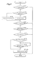
- Figure 3 is a flowchart showing the process of forced activation of the VSA upon occurrence of an abnormal condition in the rear wheel steering control shown in Figure 2 .
- the abnormal condition processing unit 44 determines if the abnormal condition is caused by a fault of the toe angle sensors 26 (such as when the detection signal is not available owing to the breaking of wire and so on) in step ST102. If the toe angle sensors 26 are not faulty (ST102: no), the abnormal condition processing unit 44 computes the toe out magnitude from the detection signal of the toe angle sensors 26 in step ST103, and determines if the detection value is greater than a prescribed threshold value in step ST104. This threshold value can be determined by considering how the toe out magnitude of the rear wheels affects the motion stability of the vehicle.
- the abnormal condition processing unit 44 sets the toe out magnitude to a prescribed maximum value as a fail safe action in step ST105, and the program flow advances to step ST104.
- the abnormal condition processing unit 44 determines if the vehicle speed detected by the vehicle sensor 21 is greater than a prescribed threshold value in step ST106. This threshold value can be determined by considering how the vehicle speed affects the motion stability of the vehicle. It should be noted that a toe out condition is particularly harmful in maintaining the motion stability of the vehicle according to the study conducted by the inventors. If the detected vehicle speed is greater than the threshold value (ST106: yes), the abnormal condition processing unit 44 determines if the VSA control is turned off in step ST107. If the VSA control is turned off (ST107: yes), it is then determined if it is caused by the turning off operation of the VSA switch 27 in step ST108. The determination process in step ST108 may be executed in such a manner that the VSA-ECU 17 stores the operation information of the VSA switch 27 after starting the engine in prescribed memory, and the abnormal condition processing unit 44 acquires this operation information.
- step ST104 if the computed value of the toe out magnitude is found to be smaller than the prescribed threshold value in step ST104 (no), the detected vehicle speed is smaller than the threshold value in ST106 (no) or the VSA control is not turned off in ST107 (no), the program flow returns to step ST101.
- the abnormal condition processing unit 44 promptly switches over the VSA 32 from the turned off state to the turned on state by forwarding a forced actuation signal to the VSA-ECU 17 in step ST110. If the VSA switch 27 is turned off following the starting of the engine (ST108: yes), the elapsed time from the time when the VSA switch 27 was turned off is measured by using the timer 45 in step ST109, and this continues until a prescribed time period (threshold value) has elapsed, and the VSA 32 is switched over from the off state to the on state in step ST110.
- the timer 45 starts counting time to measure the elapsed time, and this continues until the VSA 27 is manually turned on again, and the timer 45 is reset.
- a determination map that represents the relationship between the toe out magnitude of the rear wheels and vehicle speed may be used as a combined step for determining if the VSA-on condition is met.
- the VSA-on condition when the toe out magnitude is relatively small, as its influence on vehicle motion stability is small, the VSA-on condition may be met at a relatively high vehicle speed. Conversely, when the toe out magnitude is relatively large, as its influence on the vehicle motion stability is significant, the VSA-on condition may be met at a relatively low vehicle speed.
- the abnormal condition processing unit 44 looks up the map of Figure 4 according to the information on the toe out magnitude of the rear wheels 5 and vehicle speed, and executes the process that leads to step ST107, when the toe out magnitude and vehicle speed fall in the area (hatched area) in which the toe out magnitude and vehicle speed satisfy the VSA-on condition.
- the VSA control is forced into the on condition, the vehicle motion stability is prevented from being impaired to a significant extent.
- the VSA can be property operated so that the impairment of the vehicle motion stability can be prevented in an effective manner.
- the VSA switch when the VSA switch is turned off by a vehicle operator, by suspending or delaying the switch over of the VSA to the on state for a prescribed period of time, the driving effort of the vehicle operator while the VSA is turned off is not obstructed, and this contributes to the prevention of impairment of the vehicle motion stability
- the abnormal condition processing unit (as well as the timer) may not be provided in the STG-ECU, but may also be provided in the VSA-ECU.
- the EPS-ECU may also be incorporated in the foregoing system to provide an option in the overall control of the vehicle.
Landscapes
- Engineering & Computer Science (AREA)
- Chemical & Material Sciences (AREA)
- Combustion & Propulsion (AREA)
- Transportation (AREA)
- Mechanical Engineering (AREA)
- Physics & Mathematics (AREA)
- Mathematical Physics (AREA)
- Theoretical Computer Science (AREA)
- Steering Control In Accordance With Driving Conditions (AREA)
- Steering-Linkage Mechanisms And Four-Wheel Steering (AREA)
- Automatic Cycles, And Cycles In General (AREA)
- Power Steering Mechanism (AREA)
Abstract
Description
- The present invention relates to a rear wheel steering vehicle that can steer the rear wheels of the vehicle depending on a running condition of the vehicle, and in particular to a rear wheel steering vehicle equipped with a vehicle motion stability control system that can be selectively turned on and off.
- In a known rear wheel steering vehicle, an actuator is provided between a link mechanism that determines the steering angle and the vehicle body, and the steering angles of the right and left wheels are individually varied depending on the cornering condition of the vehicle by extending and retracting the actuator so as to change the dimension between the vehicle body and link mechanism. See Japanese patent laid open publication (kokai) No.
09-030438 - In connection with rear wheel steering vehicles equipped with a vehicle motion stability control system, it is known to prohibit the control action of the vehicle motion stability control system when the rear wheel steering device has become faulty and is thereby rendered incapable of performing a normal rear wheel steering. See Japanese patent laid open publication (kokai) No.
09-123889 - In the rear wheel steering vehicle disclosed in
patent document 1, upon occurrence of a failure in the rear wheel steering control device, the control by the vehicle motion stability control system is disabled. However, if the rear wheels are caused to be fixed in a certain condition (such as a toe out condition) owing to the occurrence of a failure (such as system down) of the rear wheel steering control device, the motion stability of the vehicle when traveling straight ahead or making a turn may be impaired. Therefore, if the vehicle motion stability control system is capable of operating properly, it is desirable to activate the vehicle motion stability control system upon occurrence of an abnormal condition in the rear wheel steering control device so as to achieve a motion stability of the vehicle. In particular, if the vehicle is equipped with a vehicle motion stability control system that can be selectively turned on and off, it is necessary to force the vehicle motion stability control system to be turned on when the vehicle motion stability control system is turned off. - In view of such problems of the prior art, a primary object of the present invention is to provide a rear wheel steering vehicle that can prevent vehicle motion stability from being impaired upon occurrence of a failure of the rear wheel steering control while vehicle motion stability control system is turned off by positively activating the vehicle motion stability control system.
- According to the present invention, such an object can be accomplished by providing a rear wheel steering vehicle equipped with a vehicle motion stability control system that can be selectively switched on and off, comprising: a rear wheel steering device including a rear wheel actuator that steers a right and left rear wheel and a rear wheel steering control unit that controls the rear wheel steering actuator; and an abnormal condition processing unit that turns on the vehicle motion stability control system upon detection of an abnormal condition of the rear wheel rear wheel steering device while the vehicle motion stability control system is turned off.
- Thus, when the rear wheel steering device becomes faulty while the vehicle motion stability control system is turned off or otherwise deactivated, the abnormal condition processing unit turns on or activates the motion stability control system, and this prevents the motion stability of the vehicle from being impaired by the faulty condition of the rear wheel steering device.
- According to a preferred embodiment of the present invention, the rear wheel steering device further comprises a toe angle sensor for detecting a rear wheel toe angle, and the abnormal condition processing unit turns on the vehicle motion stability control system only when a toe out condition of the rear wheels is detected. As a toe out condition is particularly undesirable for the motion stability of the vehicle, this feature is particularly effective in promoting the motion stability of the vehicle while minimizing the impact of the abnormal condition processing unit on the operation of the vehicle motion stability control system. It is particularly the case if the abnormal condition processing unit turns on the vehicle motion stability control system only when a toe out magnitude of the rear wheels has exceeded a prescribed threshold value.
- As the vehicle speed has a strong influence of the motion stability of the vehicle, it is desirable if the vehicle further comprises a vehicle speed sensor, and the abnormal condition processing unit turns on the vehicle motion stability control system only when a detected vehicle speed meets a prescribed condition.
- According a certain aspect of the present invention, the vehicle further comprises a manual switch for switching over the vehicle motion stability control system between a turned on condition and a turned off condition, and the abnormal condition processing unit turns on the vehicle motion stability control system with a prescribed time delay when the vehicle motion stability control system is brought to a turned off condition by being previously turned off manually by using the manual switch. Alternatively, the vehicle may be configures such that the manual switch totally overrides the abnormal condition processing unit so that the abnormal condition processing unit does not turn on the vehicle motion stability control system at all when the vehicle motion stability control system is brought to a turned off condition by being previously turned off manually by using the manual switch.
- Thereby, in case the vehicle operator wishes to temporarily turn off the vehicle motion stability control system under a certain operating condition of the vehicle, the vehicle motion stability control system can be turned on without obstructing the vehicle operator's effort to control the vehicle.
- Now the present invention is described in the following with reference to the appended drawings, in which:
-
Figure 1 is a block diagram of a vehicle equipped with a rear wheel steering device embodying the present invention; -
Figure 2 is a functional block diagram of the rear wheel steering device of the present invention; -
Figure 3 is a flowchart of a forced activation control for a VSA according to the present invention; and -
Figure 4 is a graph representing a map for determining a condition for turning on the VSA in the VSA forced actuation control. - Now the present invention is described in the following with reference to the appended drawings, in which each wheel and associated components such as a tire and a suspension system are denoted with suffixes such as R and L in addition to the corresponding numeral to indicate the positioning of the corresponding component such as "left
rear wheel 5L and rightrear wheel 5R". When the various components are generally referred to, they are collectively denoted only with the corresponding numeral such "rear wheels 5". -
Figure 1 is a schematic diagram of a motor vehicle equipped with a rear wheel steering device embodying the present invention, andFigure 2 is a functional block diagram of the rear wheel steering device. - Referring to
Figure 1 , the vehicle (rear wheel steering vehicle) 1 comprises a pair offront wheels tires rear wheels tires vehicle 1 further comprises a frontwheel steering device 9 for directly steering the right and leftfront wheels steering wheel 8, an EPS (electric power steering)system 15 for providing a power assist to the frontwheel steering device 9 and a pair ofactuators knuckles wheels suspension systems 7L and 7R and configured to individually change the steering angles of therear wheels Brakes brakes hydraulic unit 14 that supplies actuating oil under pressure to these brakes 12 and 13 as required. - The
vehicle 1 further comprises various control units such as a EPS-ECU (EPS electronic control unit) (not shown in the drawing) incorporated in theEPS device 15 for controlling the operation of theEPS device 15, a STG-ECU (steering electronic control unit) 16 for controlling the steering of the rear wheels as will be described hereinafter, a VSA-ECU 17 for controlling a VSA (vehicle stability assist device) and a ENG-ECU 18 for controlling an engine E. TheseECUs 16 to 18 are connected to various sensors such as avehicle speed sensor 21 for detecting a vehicle speed, asteering angle sensor 22 for detecting an angular position of thesteering wheel 8, ayaw rate sensor 23 for detecting a yaw rate of the vehicle, alateral G sensor 24 for detecting a lateral acceleration of the vehicle, a fore-and-aft G sensor 25 for detecting a fore-and-aft acceleration of the vehicle, and also totoe angle sensors rear wheels corresponding actuators sensors 21 1 to 26 are used for the control of theECUs 16 to 18. AVSA switch 27 is provided adjacent to a driver's seat not shown in the drawings to enable the VSA-ECU 17 to be manually turned on and off as desired. - The STG-
ECU 16, VSA-ECU 17 and ENG-ECU 18 are each provided with a microcomputer, ROM, RAM, a peripheral circuit, an input/output interface and various drivers, and are mutually connected with one another via appropriate communication lines. In thevehicle 1, the STG-ECU 16 forms a rearwheel steering device 31 jointly with thesensors 21 to 26 andactuators VSA 32 jointly with thesensors 21 to 25 andVSA switch 27. - As shown in
Figure 2 , the STG-ECU 16 essentially consists of aninput interface 41 that are connected to thevarious sensors 21 to 26 and receive detection signals from these sensors, a target actuatorposition determining unit 42 for determining target actuation positions of the actuators 11 according to the information obtained from thesensors 21 to 26, a drivesignal generating unit 43 for generating a drive signal for controlling each of the actuators 11, an abnormalcondition processing unit 44 for turning on theVSA 32 when an abnormal condition has occurred to the rear wheel steering control while theVSA 32 is turned off under a prescribed condition as will be described hereinafter, atimer 45 for measuring time and anoutput interface 46 connected to the actuators 11. - The target actuator
position determining unit 42 determines target actuator positions of the actuators 11 according to the running condition of the vehicle (that may include the detection signals of thevehicle speed sensor 21 andsteering angle sensor 22 in the illustrated embodiment), and forwards the information on the target actuator positions to the drivesignal generating unit 43 as required. In this case, the target actuator positions can be determined by using a formula including running condition variables of the vehicle such as the vehicle speed and steering angle as variables or by looking up a map representing a relationship between the target actuator positions and running condition variables such as vehicle speed and steering angle. - As will be discussed in more detail hereinafter, upon detection of an abnormal condition of the rear
wheel steering device 31, the abnormalcondition processing unit 44 determines if a prescribed condition for forcing theVSA 32 to be turned on (VSA-on condition) is met. If the condition is met, the abnormalcondition processing unit 44 forwards a forced actuation signal to the VSA-ECU 17 so that theVSA 32 moves on or switches over from the turned off state to the turned on state. The abnormal condition of the rearwheel steering device 31 as used herein may include the case where the toe angles of the rear wheels 5 are fixed at a certain angle owing to a failure in the system and the case where the detection of the toe angles of the rear wheels has become impossible owing a failure associated with the toe angle sensors 26. The VSA-on condition may include the toe out magnitude of the rear wheels computed from the detection signals of the toe angle sensors 26 and the vehicle speed detected by the vehicle speed sensor. - The VSA-ECU 17 determines the control variables of the
hydraulic unit 14 and ENG-ECU 18 according to the detection signals of thevarious sensors 21 to 25, and forwards the determined control variable values to thehydraulic unit 14 and ENG-ECU 18 as prescribed control signals. The VSA control of the VSA-ECU 17 contributes to the stabilization of vehicle motion by providing an ABS action for preventing the locking of the wheels at the time of braking, a TSC action that prevents the free rotation of the wheels at the time of acceleration, and other per se known control actions such as those that control the side slip of the vehicle when cornering. At the same time, the vehicle operator is enabled to turn off the VSA-ECU 17, if so desired, to temporarily interrupt the VSA control by operating theVSA switch 27 under a certain condition such as when the tires are stuck in mud often caused by rain or snow, and this helps the vehicle to get out of the mud. Upon occurrence of an abnormal condition in the rear steering control, even when the VSA-ECU 17 is in a turned off state, the VSA-ECU 17 is turned back on by receiving the forced activation signal from the abnormalcondition processing unit 44 of the STG-ECU 16. -
Figure 3 is a flowchart showing the process of forced activation of the VSA upon occurrence of an abnormal condition in the rear wheel steering control shown inFigure 2 . - First of all, upon detection of an abnormal condition (ST101: yes), the abnormal
condition processing unit 44 determines if the abnormal condition is caused by a fault of the toe angle sensors 26 (such as when the detection signal is not available owing to the breaking of wire and so on) in step ST102. If the toe angle sensors 26 are not faulty (ST102: no), the abnormalcondition processing unit 44 computes the toe out magnitude from the detection signal of the toe angle sensors 26 in step ST103, and determines if the detection value is greater than a prescribed threshold value in step ST104. This threshold value can be determined by considering how the toe out magnitude of the rear wheels affects the motion stability of the vehicle. On the other hand, if the toe angle sensors 26 are found to be faulty (ST102: yes), as it is impossible to determine the actual toe out magnitude of the rear wheels in such a case, the abnormalcondition processing unit 44 sets the toe out magnitude to a prescribed maximum value as a fail safe action in step ST105, and the program flow advances to step ST104. - If the computed value of the toe out magnitude is found to be greater than the prescribed threshold value in step ST104 (yes), the abnormal
condition processing unit 44 determines if the vehicle speed detected by thevehicle sensor 21 is greater than a prescribed threshold value in step ST106. This threshold value can be determined by considering how the vehicle speed affects the motion stability of the vehicle. It should be noted that a toe out condition is particularly harmful in maintaining the motion stability of the vehicle according to the study conducted by the inventors. If the detected vehicle speed is greater than the threshold value (ST106: yes), the abnormalcondition processing unit 44 determines if the VSA control is turned off in step ST107. If the VSA control is turned off (ST107: yes), it is then determined if it is caused by the turning off operation of theVSA switch 27 in step ST108. The determination process in step ST108 may be executed in such a manner that the VSA-ECU 17 stores the operation information of theVSA switch 27 after starting the engine in prescribed memory, and the abnormalcondition processing unit 44 acquires this operation information. - On the other hand, if the computed value of the toe out magnitude is found to be smaller than the prescribed threshold value in step ST104 (no), the detected vehicle speed is smaller than the threshold value in ST106 (no) or the VSA control is not turned off in ST107 (no), the program flow returns to step ST101.
- If the
VSA switch 27 is not turned off following the starting of the engine (ST108: no), the abnormalcondition processing unit 44 promptly switches over theVSA 32 from the turned off state to the turned on state by forwarding a forced actuation signal to the VSA-ECU 17 in step ST110. If theVSA switch 27 is turned off following the starting of the engine (ST108: yes), the elapsed time from the time when theVSA switch 27 was turned off is measured by using thetimer 45 in step ST109, and this continues until a prescribed time period (threshold value) has elapsed, and theVSA 32 is switched over from the off state to the on state in step ST110. - In this case, if the
VSA switch 27 is turned off following the starting of the engine, thetimer 45 starts counting time to measure the elapsed time, and this continues until theVSA 27 is manually turned on again, and thetimer 45 is reset. - In the forced actuation control for the VSA discussed above, because the extent of the impairment of the vehicle motion stability is increased with the toe out magnitude at which the rear wheels are fixed owing to an abnormal condition of the rear wheel steering control, it is necessary that the VSA is switched over to the turned on state at a relatively low vehicle speed. Therefore, instead of steps ST104 and ST106 shown in
Figure 3 , a determination map that represents the relationship between the toe out magnitude of the rear wheels and vehicle speed may be used as a combined step for determining if the VSA-on condition is met. - In this case, as indicated by the hatched area in
Figure 4 , when the toe out magnitude is relatively small, as its influence on vehicle motion stability is small, the VSA-on condition may be met at a relatively high vehicle speed. Conversely, when the toe out magnitude is relatively large, as its influence on the vehicle motion stability is significant, the VSA-on condition may be met at a relatively low vehicle speed. Therefore, instead of relying on steps ST104 and ST106, in the combined alternate step, the abnormalcondition processing unit 44 looks up the map ofFigure 4 according to the information on the toe out magnitude of the rear wheels 5 and vehicle speed, and executes the process that leads to step ST107, when the toe out magnitude and vehicle speed fall in the area (hatched area) in which the toe out magnitude and vehicle speed satisfy the VSA-on condition. - In this way, in the vehicle described above, even when an abnormal condition such as the freezing or fixing of the rear wheel toe angle should occur to the rear wheel steering control while the VSA is turned off, because the VSA control is forced into the on condition, the vehicle motion stability is prevented from being impaired to a significant extent. In particular, by forcing the VSA into the turned on state only when the rear wheels are in a toe out condition, the VSA can be property operated so that the impairment of the vehicle motion stability can be prevented in an effective manner. Furthermore, when the VSA switch is turned off by a vehicle operator, by suspending or delaying the switch over of the VSA to the on state for a prescribed period of time, the driving effort of the vehicle operator while the VSA is turned off is not obstructed, and this contributes to the prevention of impairment of the vehicle motion stability
- Although the present invention has been described in terms of a preferred embodiment thereof, it is obvious to a person skilled in the art that various alterations and modifications are possible without departing from the scope of the present invention which is set forth in the appended claims. For instance, the abnormal condition processing unit (as well as the timer) may not be provided in the STG-ECU, but may also be provided in the VSA-ECU. The EPS-ECU may also be incorporated in the foregoing system to provide an option in the overall control of the vehicle.
- The contents of the original Japanese patent application on which the Paris Convention priority claim is made for the present application are incorporated in this application by reference.
-
- 1
- vehicle
- 5
- rear wheel
- 11
- actuator
- 16
- STG-ECU
- 17
- VSA-ECU
- 21
- vehicle speed sensor
- 22
- steering angle sensor
- 23
- yaw rate sensor
- 24
- lateral G sensor
- 25
- for-and-aft sensor
- 26
- toe angle sensor
- 27
- VSA sensor
- 31
- rear wheel steering device
- 32
- VSA
- 44
- abnormal condition processing unit
- 45
- timer
Claims (5)
- A rear wheel steering vehicle equipped with a vehicle motion stability control system that can be selectively switched on and off, comprising:a rear wheel steering device including a rear wheel actuator that steers a right and left rear wheel and a rear wheel steering control unit that controls the rear wheel steering actuator; andan abnormal condition processing unit that turns on the vehicle motion stability control system upon detection of an abnormal condition of the rear wheel rear wheel steering device while the vehicle motion stability control system is turned off.
- The rear wheel steering vehicle according to claim 1, wherein the rear wheel steering device further comprises a toe angle sensor for detecting a rear wheel toe angle, and the abnormal condition processing unit turns on the vehicle motion stability control system only when a toe out condition of the rear wheels is detected.
- The rear wheel steering vehicle according to claim 2, wherein the abnormal condition processing unit turns on the vehicle motion stability control system only when a toe out magnitude of the rear wheels has exceeded a prescribed threshold value.
- The rear wheel steering vehicle according to claim 1, further comprising a vehicle speed sensor, the abnormal condition processing unit turning on the vehicle motion stability control system only when a detected vehicle speed meets a prescribed condition.
- The rear wheel steering vehicle according to claim 1, further comprising a manual switch for switching over the vehicle motion stability control system between a turned on condition and a turned off condition, the abnormal condition processing unit turning on the vehicle motion stability control system with a prescribed time delay when the vehicle motion stability control system is brought to a turned off condition by being previously turned off manually by using the manual switch.
Applications Claiming Priority (2)
| Application Number | Priority Date | Filing Date | Title |
|---|---|---|---|
| JP2008059213 | 2008-03-10 | ||
| PCT/JP2009/000357 WO2009113233A1 (en) | 2008-03-10 | 2009-01-30 | Rear wheel steering vehicle |
Publications (3)
| Publication Number | Publication Date |
|---|---|
| EP2210796A1 true EP2210796A1 (en) | 2010-07-28 |
| EP2210796A4 EP2210796A4 (en) | 2010-12-22 |
| EP2210796B1 EP2210796B1 (en) | 2011-08-17 |
Family
ID=41064907
Family Applications (1)
| Application Number | Title | Priority Date | Filing Date |
|---|---|---|---|
| EP09718978A Not-in-force EP2210796B1 (en) | 2008-03-10 | 2009-01-30 | Rear wheel steering vehicle |
Country Status (6)
| Country | Link |
|---|---|
| US (1) | US9145167B2 (en) |
| EP (1) | EP2210796B1 (en) |
| JP (1) | JP5320286B2 (en) |
| CN (1) | CN101918265B (en) |
| AT (1) | ATE520581T1 (en) |
| WO (1) | WO2009113233A1 (en) |
Families Citing this family (10)
| Publication number | Priority date | Publication date | Assignee | Title |
|---|---|---|---|---|
| EP1975041B1 (en) * | 2007-03-27 | 2013-10-16 | Honda Motor Co., Ltd. | Steering system |
| FR2991960B1 (en) * | 2012-06-14 | 2015-10-16 | Renault Sas | METHOD FOR SECURING THE CONTROL OF THE REAR WHEELS OF A MOTOR VEHICLE EQUIPPED WITH AN ELECTRIC POWER STEERING |
| US8666600B2 (en) * | 2012-06-20 | 2014-03-04 | Honda Motor Co., Ltd. | Rear toe control system and method |
| JP2014234001A (en) * | 2013-05-31 | 2014-12-15 | Ntn株式会社 | Stop control device for vehicle |
| KR101770865B1 (en) * | 2013-08-20 | 2017-08-23 | 주식회사 만도 | Active Rear Wheel Steering Apparatus Control Method |
| KR101988510B1 (en) | 2014-04-11 | 2019-09-30 | 주식회사 만도 | Apparatus and method for electronic stability control of vehicle |
| CN110023129B (en) * | 2016-12-13 | 2022-04-22 | 本田技研工业株式会社 | Control device for torque distribution device |
| US10486664B2 (en) | 2017-05-31 | 2019-11-26 | Ford Global Technologies, Llc | Traction and stability control system |
| CN109723251B (en) * | 2019-01-29 | 2023-10-20 | 温州米修实业有限公司 | Automatic cleaning vehicle for swimming pool |
| CN119305628A (en) * | 2023-07-11 | 2025-01-14 | 罗伯特·博世有限公司 | Vehicle steering system and method for controlling vehicle steering |
Family Cites Families (21)
| Publication number | Priority date | Publication date | Assignee | Title |
|---|---|---|---|---|
| JPH05201343A (en) * | 1992-01-30 | 1993-08-10 | Daihatsu Motor Co Ltd | Steering control method for rear wheel for four-wheel steering vehicle |
| JPH08142893A (en) * | 1994-11-16 | 1996-06-04 | Toyota Motor Corp | Vehicle control system |
| JP3067564B2 (en) * | 1995-01-12 | 2000-07-17 | トヨタ自動車株式会社 | Vehicle turning control device |
| JP3476972B2 (en) | 1995-07-17 | 2003-12-10 | 本田技研工業株式会社 | Rear wheel steering device |
| JP3348579B2 (en) | 1995-10-30 | 2002-11-20 | トヨタ自動車株式会社 | Vehicle behavior control device |
| JP3301325B2 (en) * | 1996-11-18 | 2002-07-15 | トヨタ自動車株式会社 | Vehicle state quantity acquisition device |
| JP2000052955A (en) * | 1998-08-07 | 2000-02-22 | Koyo Seiko Co Ltd | Steering system for vehicle |
| JP2001099676A (en) * | 1999-09-30 | 2001-04-13 | Toshiba Corp | Positioning receiver |
| JP2001260704A (en) * | 2000-03-22 | 2001-09-26 | Fujitsu Ten Ltd | Travel assist system |
| JP2001322557A (en) * | 2000-05-17 | 2001-11-20 | Toyota Motor Corp | Multi-wheel independent steering system for vehicles |
| US6721644B2 (en) * | 2000-08-02 | 2004-04-13 | Alfred B. Levine | Vehicle drive override subsystem |
| DE10218698A1 (en) * | 2002-04-26 | 2003-11-13 | Bosch Gmbh Robert | Driver assistance system |
| JP4069754B2 (en) * | 2003-02-07 | 2008-04-02 | 日産自動車株式会社 | Vehicle motion control device |
| JP4230947B2 (en) * | 2004-03-22 | 2009-02-25 | 株式会社日立製作所 | Vehicle control device |
| JP4457762B2 (en) * | 2004-06-09 | 2010-04-28 | 日産自動車株式会社 | Vehicle braking force control device |
| US20070055431A1 (en) * | 2005-09-07 | 2007-03-08 | Weiwen Deng | Method and apparatus for preview-based vehicle lateral control |
| JP4604985B2 (en) * | 2005-11-28 | 2011-01-05 | トヨタ自動車株式会社 | Vehicle travel control device |
| JP4448838B2 (en) * | 2006-08-25 | 2010-04-14 | 本田技研工業株式会社 | Vehicle toe angle variable control device |
| KR100748350B1 (en) * | 2006-09-12 | 2007-08-09 | 주식회사 만도 | Rear wheel toe control of car |
| JP2008168779A (en) * | 2007-01-11 | 2008-07-24 | Toyota Motor Corp | Brake control device for vehicle |
| JP4359315B2 (en) * | 2007-03-27 | 2009-11-04 | 本田技研工業株式会社 | All-wheel steering device for vehicle |
-
2009
- 2009-01-30 CN CN200980102528.7A patent/CN101918265B/en not_active Expired - Fee Related
- 2009-01-30 AT AT09718978T patent/ATE520581T1/en not_active IP Right Cessation
- 2009-01-30 JP JP2009512091A patent/JP5320286B2/en not_active Expired - Fee Related
- 2009-01-30 US US12/921,685 patent/US9145167B2/en not_active Expired - Fee Related
- 2009-01-30 EP EP09718978A patent/EP2210796B1/en not_active Not-in-force
- 2009-01-30 WO PCT/JP2009/000357 patent/WO2009113233A1/en not_active Ceased
Non-Patent Citations (2)
| Title |
|---|
| No further relevant documents disclosed * |
| See also references of WO2009113233A1 * |
Also Published As
| Publication number | Publication date |
|---|---|
| CN101918265A (en) | 2010-12-15 |
| JPWO2009113233A1 (en) | 2011-07-21 |
| US9145167B2 (en) | 2015-09-29 |
| EP2210796A4 (en) | 2010-12-22 |
| US20110046851A1 (en) | 2011-02-24 |
| EP2210796B1 (en) | 2011-08-17 |
| JP5320286B2 (en) | 2013-10-23 |
| CN101918265B (en) | 2014-01-29 |
| WO2009113233A1 (en) | 2009-09-17 |
| ATE520581T1 (en) | 2011-09-15 |
Similar Documents
| Publication | Publication Date | Title |
|---|---|---|
| EP2210796B1 (en) | Rear wheel steering vehicle | |
| US10661827B2 (en) | Motor vehicle for piloted driving comprising a front axle steering system and a rear axle steering system | |
| CN109963766B (en) | Control steer-by-wire type steering system | |
| JP4267294B2 (en) | Brake control device for vehicle | |
| JP2003500275A (en) | Steering device and steering method | |
| US7683765B2 (en) | Tactile signaling | |
| KR100866816B1 (en) | Vehicle control apparatus for quickly dealing with communication abnormality in communication means between calculation control devices | |
| US10435073B2 (en) | Method for operating a steering system and steering system | |
| JP4211518B2 (en) | Electric power steering control device | |
| JP4382345B2 (en) | Vehicle steering system | |
| JP2008001286A (en) | Collision avoidance system | |
| JPH02227381A (en) | Cooperative controller of rear-wheel steering and power steering for vehicle | |
| JP7793048B2 (en) | Power boost when steering system performance is degraded | |
| JP4742504B2 (en) | Drive control device | |
| JP4269594B2 (en) | Operation control device for vehicle occupant protection device | |
| US10137930B2 (en) | Method for controlling a steering actuator comprising a counter-steering step before a deactivation step | |
| JP2009220639A (en) | Electronic brake control device of vehicle | |
| JP3705256B2 (en) | Automatic steering device | |
| JP5432648B2 (en) | Power line sharing device | |
| JP5271640B2 (en) | Control device for electric power steering | |
| JP2003019969A (en) | By-wire steering system | |
| JP3027567B2 (en) | Vehicle turning control device | |
| KR100247338B1 (en) | Vehicle steering | |
| JP5173894B2 (en) | Vehicle behavior control device | |
| JPS62253564A (en) | Car speed sensor back-up device for vehicle |
Legal Events
| Date | Code | Title | Description |
|---|---|---|---|
| PUAI | Public reference made under article 153(3) epc to a published international application that has entered the european phase |
Free format text: ORIGINAL CODE: 0009012 |
|
| 17P | Request for examination filed |
Effective date: 20100526 |
|
| AK | Designated contracting states |
Kind code of ref document: A1 Designated state(s): AT BE BG CH CY CZ DE DK EE ES FI FR GB GR HR HU IE IS IT LI LT LU LV MC MK MT NL NO PL PT RO SE SI SK TR |
|
| AX | Request for extension of the european patent |
Extension state: AL BA RS |
|
| A4 | Supplementary search report drawn up and despatched |
Effective date: 20101124 |
|
| GRAP | Despatch of communication of intention to grant a patent |
Free format text: ORIGINAL CODE: EPIDOSNIGR1 |
|
| RIC1 | Information provided on ipc code assigned before grant |
Ipc: B62D 7/08 20060101ALI20110120BHEP Ipc: B62D 6/00 20060101AFI20110120BHEP Ipc: B60W 30/00 20060101ALI20110120BHEP Ipc: B60W 30/02 20060101ALI20110120BHEP Ipc: B60W 50/02 20060101ALI20110120BHEP Ipc: B62D 5/04 20060101ALI20110120BHEP Ipc: B62D 101/00 20060101ALI20110120BHEP Ipc: B62D 103/00 20060101ALI20110120BHEP Ipc: B62D 111/00 20060101ALI20110120BHEP Ipc: B62D 113/00 20060101ALI20110120BHEP Ipc: B62D 137/00 20060101ALI20110120BHEP |
|
| GRAC | Information related to communication of intention to grant a patent modified |
Free format text: ORIGINAL CODE: EPIDOSCIGR1 |
|
| DAX | Request for extension of the european patent (deleted) | ||
| GRAS | Grant fee paid |
Free format text: ORIGINAL CODE: EPIDOSNIGR3 |
|
| GRAA | (expected) grant |
Free format text: ORIGINAL CODE: 0009210 |
|
| RAP1 | Party data changed (applicant data changed or rights of an application transferred) |
Owner name: HONDA MOTOR CO., LTD. |
|
| RIN1 | Information on inventor provided before grant (corrected) |
Inventor name: SASAKI, HIROAKI Inventor name: YANAGI, TAKASHI Inventor name: ONAYA, HIDEKI |
|
| AK | Designated contracting states |
Kind code of ref document: B1 Designated state(s): AT BE BG CH CY CZ DE DK EE ES FI FR GB GR HR HU IE IS IT LI LT LU LV MC MK MT NL NO PL PT RO SE SI SK TR |
|
| REG | Reference to a national code |
Ref country code: GB Ref legal event code: FG4D |
|
| REG | Reference to a national code |
Ref country code: CH Ref legal event code: EP |
|
| REG | Reference to a national code |
Ref country code: IE Ref legal event code: FG4D |
|
| REG | Reference to a national code |
Ref country code: DE Ref legal event code: R096 Ref document number: 602009002206 Country of ref document: DE Effective date: 20111027 |
|
| REG | Reference to a national code |
Ref country code: NL Ref legal event code: VDEP Effective date: 20110817 |
|
| LTIE | Lt: invalidation of european patent or patent extension |
Effective date: 20110817 |
|
| PG25 | Lapsed in a contracting state [announced via postgrant information from national office to epo] |
Ref country code: PT Free format text: LAPSE BECAUSE OF FAILURE TO SUBMIT A TRANSLATION OF THE DESCRIPTION OR TO PAY THE FEE WITHIN THE PRESCRIBED TIME-LIMIT Effective date: 20111219 Ref country code: NO Free format text: LAPSE BECAUSE OF FAILURE TO SUBMIT A TRANSLATION OF THE DESCRIPTION OR TO PAY THE FEE WITHIN THE PRESCRIBED TIME-LIMIT Effective date: 20111117 Ref country code: FI Free format text: LAPSE BECAUSE OF FAILURE TO SUBMIT A TRANSLATION OF THE DESCRIPTION OR TO PAY THE FEE WITHIN THE PRESCRIBED TIME-LIMIT Effective date: 20110817 Ref country code: SE Free format text: LAPSE BECAUSE OF FAILURE TO SUBMIT A TRANSLATION OF THE DESCRIPTION OR TO PAY THE FEE WITHIN THE PRESCRIBED TIME-LIMIT Effective date: 20110817 Ref country code: LT Free format text: LAPSE BECAUSE OF FAILURE TO SUBMIT A TRANSLATION OF THE DESCRIPTION OR TO PAY THE FEE WITHIN THE PRESCRIBED TIME-LIMIT Effective date: 20110817 Ref country code: NL Free format text: LAPSE BECAUSE OF FAILURE TO SUBMIT A TRANSLATION OF THE DESCRIPTION OR TO PAY THE FEE WITHIN THE PRESCRIBED TIME-LIMIT Effective date: 20110817 Ref country code: IS Free format text: LAPSE BECAUSE OF FAILURE TO SUBMIT A TRANSLATION OF THE DESCRIPTION OR TO PAY THE FEE WITHIN THE PRESCRIBED TIME-LIMIT Effective date: 20111217 |
|
| REG | Reference to a national code |
Ref country code: AT Ref legal event code: MK05 Ref document number: 520581 Country of ref document: AT Kind code of ref document: T Effective date: 20110817 |
|
| PG25 | Lapsed in a contracting state [announced via postgrant information from national office to epo] |
Ref country code: CY Free format text: LAPSE BECAUSE OF FAILURE TO SUBMIT A TRANSLATION OF THE DESCRIPTION OR TO PAY THE FEE WITHIN THE PRESCRIBED TIME-LIMIT Effective date: 20110817 Ref country code: LV Free format text: LAPSE BECAUSE OF FAILURE TO SUBMIT A TRANSLATION OF THE DESCRIPTION OR TO PAY THE FEE WITHIN THE PRESCRIBED TIME-LIMIT Effective date: 20110817 Ref country code: SI Free format text: LAPSE BECAUSE OF FAILURE TO SUBMIT A TRANSLATION OF THE DESCRIPTION OR TO PAY THE FEE WITHIN THE PRESCRIBED TIME-LIMIT Effective date: 20110817 Ref country code: GR Free format text: LAPSE BECAUSE OF FAILURE TO SUBMIT A TRANSLATION OF THE DESCRIPTION OR TO PAY THE FEE WITHIN THE PRESCRIBED TIME-LIMIT Effective date: 20111118 Ref country code: AT Free format text: LAPSE BECAUSE OF FAILURE TO SUBMIT A TRANSLATION OF THE DESCRIPTION OR TO PAY THE FEE WITHIN THE PRESCRIBED TIME-LIMIT Effective date: 20110817 Ref country code: PL Free format text: LAPSE BECAUSE OF FAILURE TO SUBMIT A TRANSLATION OF THE DESCRIPTION OR TO PAY THE FEE WITHIN THE PRESCRIBED TIME-LIMIT Effective date: 20110817 |
|
| PG25 | Lapsed in a contracting state [announced via postgrant information from national office to epo] |
Ref country code: BE Free format text: LAPSE BECAUSE OF FAILURE TO SUBMIT A TRANSLATION OF THE DESCRIPTION OR TO PAY THE FEE WITHIN THE PRESCRIBED TIME-LIMIT Effective date: 20110817 |
|
| PG25 | Lapsed in a contracting state [announced via postgrant information from national office to epo] |
Ref country code: CZ Free format text: LAPSE BECAUSE OF FAILURE TO SUBMIT A TRANSLATION OF THE DESCRIPTION OR TO PAY THE FEE WITHIN THE PRESCRIBED TIME-LIMIT Effective date: 20110817 Ref country code: SK Free format text: LAPSE BECAUSE OF FAILURE TO SUBMIT A TRANSLATION OF THE DESCRIPTION OR TO PAY THE FEE WITHIN THE PRESCRIBED TIME-LIMIT Effective date: 20110817 |
|
| PG25 | Lapsed in a contracting state [announced via postgrant information from national office to epo] |
Ref country code: EE Free format text: LAPSE BECAUSE OF FAILURE TO SUBMIT A TRANSLATION OF THE DESCRIPTION OR TO PAY THE FEE WITHIN THE PRESCRIBED TIME-LIMIT Effective date: 20110817 Ref country code: RO Free format text: LAPSE BECAUSE OF FAILURE TO SUBMIT A TRANSLATION OF THE DESCRIPTION OR TO PAY THE FEE WITHIN THE PRESCRIBED TIME-LIMIT Effective date: 20110817 Ref country code: IT Free format text: LAPSE BECAUSE OF FAILURE TO SUBMIT A TRANSLATION OF THE DESCRIPTION OR TO PAY THE FEE WITHIN THE PRESCRIBED TIME-LIMIT Effective date: 20110817 |
|
| PLBE | No opposition filed within time limit |
Free format text: ORIGINAL CODE: 0009261 |
|
| STAA | Information on the status of an ep patent application or granted ep patent |
Free format text: STATUS: NO OPPOSITION FILED WITHIN TIME LIMIT |
|
| PG25 | Lapsed in a contracting state [announced via postgrant information from national office to epo] |
Ref country code: DK Free format text: LAPSE BECAUSE OF FAILURE TO SUBMIT A TRANSLATION OF THE DESCRIPTION OR TO PAY THE FEE WITHIN THE PRESCRIBED TIME-LIMIT Effective date: 20110817 |
|
| 26N | No opposition filed |
Effective date: 20120521 |
|
| PG25 | Lapsed in a contracting state [announced via postgrant information from national office to epo] |
Ref country code: MC Free format text: LAPSE BECAUSE OF NON-PAYMENT OF DUE FEES Effective date: 20120131 |
|
| REG | Reference to a national code |
Ref country code: DE Ref legal event code: R097 Ref document number: 602009002206 Country of ref document: DE Effective date: 20120521 |
|
| REG | Reference to a national code |
Ref country code: IE Ref legal event code: MM4A |
|
| PG25 | Lapsed in a contracting state [announced via postgrant information from national office to epo] |
Ref country code: HR Free format text: LAPSE BECAUSE OF FAILURE TO SUBMIT A TRANSLATION OF THE DESCRIPTION OR TO PAY THE FEE WITHIN THE PRESCRIBED TIME-LIMIT Effective date: 20120404 |
|
| PG25 | Lapsed in a contracting state [announced via postgrant information from national office to epo] |
Ref country code: IE Free format text: LAPSE BECAUSE OF NON-PAYMENT OF DUE FEES Effective date: 20120130 |
|
| PG25 | Lapsed in a contracting state [announced via postgrant information from national office to epo] |
Ref country code: MK Free format text: LAPSE BECAUSE OF FAILURE TO SUBMIT A TRANSLATION OF THE DESCRIPTION OR TO PAY THE FEE WITHIN THE PRESCRIBED TIME-LIMIT Effective date: 20110817 |
|
| PG25 | Lapsed in a contracting state [announced via postgrant information from national office to epo] |
Ref country code: ES Free format text: LAPSE BECAUSE OF FAILURE TO SUBMIT A TRANSLATION OF THE DESCRIPTION OR TO PAY THE FEE WITHIN THE PRESCRIBED TIME-LIMIT Effective date: 20111128 |
|
| PG25 | Lapsed in a contracting state [announced via postgrant information from national office to epo] |
Ref country code: BG Free format text: LAPSE BECAUSE OF FAILURE TO SUBMIT A TRANSLATION OF THE DESCRIPTION OR TO PAY THE FEE WITHIN THE PRESCRIBED TIME-LIMIT Effective date: 20111117 |
|
| PG25 | Lapsed in a contracting state [announced via postgrant information from national office to epo] |
Ref country code: MT Free format text: LAPSE BECAUSE OF FAILURE TO SUBMIT A TRANSLATION OF THE DESCRIPTION OR TO PAY THE FEE WITHIN THE PRESCRIBED TIME-LIMIT Effective date: 20110817 |
|
| REG | Reference to a national code |
Ref country code: CH Ref legal event code: PL |
|
| GBPC | Gb: european patent ceased through non-payment of renewal fee |
Effective date: 20130130 |
|
| PG25 | Lapsed in a contracting state [announced via postgrant information from national office to epo] |
Ref country code: CH Free format text: LAPSE BECAUSE OF NON-PAYMENT OF DUE FEES Effective date: 20130131 Ref country code: LI Free format text: LAPSE BECAUSE OF NON-PAYMENT OF DUE FEES Effective date: 20130131 |
|
| PG25 | Lapsed in a contracting state [announced via postgrant information from national office to epo] |
Ref country code: HR Free format text: LAPSE BECAUSE OF FAILURE TO SUBMIT A TRANSLATION OF THE DESCRIPTION OR TO PAY THE FEE WITHIN THE PRESCRIBED TIME-LIMIT Effective date: 20110817 Ref country code: GB Free format text: LAPSE BECAUSE OF NON-PAYMENT OF DUE FEES Effective date: 20130130 |
|
| PG25 | Lapsed in a contracting state [announced via postgrant information from national office to epo] |
Ref country code: TR Free format text: LAPSE BECAUSE OF FAILURE TO SUBMIT A TRANSLATION OF THE DESCRIPTION OR TO PAY THE FEE WITHIN THE PRESCRIBED TIME-LIMIT Effective date: 20110817 |
|
| PG25 | Lapsed in a contracting state [announced via postgrant information from national office to epo] |
Ref country code: LU Free format text: LAPSE BECAUSE OF NON-PAYMENT OF DUE FEES Effective date: 20120130 |
|
| PG25 | Lapsed in a contracting state [announced via postgrant information from national office to epo] |
Ref country code: HU Free format text: LAPSE BECAUSE OF FAILURE TO SUBMIT A TRANSLATION OF THE DESCRIPTION OR TO PAY THE FEE WITHIN THE PRESCRIBED TIME-LIMIT Effective date: 20090130 |
|
| REG | Reference to a national code |
Ref country code: DE Ref legal event code: R084 Ref document number: 602009002206 Country of ref document: DE |
|
| REG | Reference to a national code |
Ref country code: DE Ref legal event code: R084 Ref document number: 602009002206 Country of ref document: DE Effective date: 20141120 |
|
| REG | Reference to a national code |
Ref country code: FR Ref legal event code: PLFP Year of fee payment: 7 |
|
| PGFP | Annual fee paid to national office [announced via postgrant information from national office to epo] |
Ref country code: FR Payment date: 20150108 Year of fee payment: 7 |
|
| REG | Reference to a national code |
Ref country code: FR Ref legal event code: ST Effective date: 20160930 |
|
| PG25 | Lapsed in a contracting state [announced via postgrant information from national office to epo] |
Ref country code: FR Free format text: LAPSE BECAUSE OF NON-PAYMENT OF DUE FEES Effective date: 20160201 |
|
| PGFP | Annual fee paid to national office [announced via postgrant information from national office to epo] |
Ref country code: DE Payment date: 20190115 Year of fee payment: 11 |
|
| REG | Reference to a national code |
Ref country code: DE Ref legal event code: R119 Ref document number: 602009002206 Country of ref document: DE |
|
| PG25 | Lapsed in a contracting state [announced via postgrant information from national office to epo] |
Ref country code: DE Free format text: LAPSE BECAUSE OF NON-PAYMENT OF DUE FEES Effective date: 20200801 |