EP2210759A1 - Hybrid propulsion system, particularly for motor vehicles and boats - Google Patents
Hybrid propulsion system, particularly for motor vehicles and boats Download PDFInfo
- Publication number
- EP2210759A1 EP2210759A1 EP10150407A EP10150407A EP2210759A1 EP 2210759 A1 EP2210759 A1 EP 2210759A1 EP 10150407 A EP10150407 A EP 10150407A EP 10150407 A EP10150407 A EP 10150407A EP 2210759 A1 EP2210759 A1 EP 2210759A1
- Authority
- EP
- European Patent Office
- Prior art keywords
- air
- compressed
- engine
- propulsion system
- cylinders
- Prior art date
- Legal status (The legal status is an assumption and is not a legal conclusion. Google has not performed a legal analysis and makes no representation as to the accuracy of the status listed.)
- Withdrawn
Links
Images

Classifications
-
- B—PERFORMING OPERATIONS; TRANSPORTING
- B60—VEHICLES IN GENERAL
- B60K—ARRANGEMENT OR MOUNTING OF PROPULSION UNITS OR OF TRANSMISSIONS IN VEHICLES; ARRANGEMENT OR MOUNTING OF PLURAL DIVERSE PRIME-MOVERS IN VEHICLES; AUXILIARY DRIVES FOR VEHICLES; INSTRUMENTATION OR DASHBOARDS FOR VEHICLES; ARRANGEMENTS IN CONNECTION WITH COOLING, AIR INTAKE, GAS EXHAUST OR FUEL SUPPLY OF PROPULSION UNITS IN VEHICLES
- B60K6/00—Arrangement or mounting of plural diverse prime-movers for mutual or common propulsion, e.g. hybrid propulsion systems comprising electric motors and internal combustion engines
- B60K6/08—Prime-movers comprising combustion engines and mechanical or fluid energy storing means
- B60K6/12—Prime-movers comprising combustion engines and mechanical or fluid energy storing means by means of a chargeable fluidic accumulator
-
- B—PERFORMING OPERATIONS; TRANSPORTING
- B60—VEHICLES IN GENERAL
- B60K—ARRANGEMENT OR MOUNTING OF PROPULSION UNITS OR OF TRANSMISSIONS IN VEHICLES; ARRANGEMENT OR MOUNTING OF PLURAL DIVERSE PRIME-MOVERS IN VEHICLES; AUXILIARY DRIVES FOR VEHICLES; INSTRUMENTATION OR DASHBOARDS FOR VEHICLES; ARRANGEMENTS IN CONNECTION WITH COOLING, AIR INTAKE, GAS EXHAUST OR FUEL SUPPLY OF PROPULSION UNITS IN VEHICLES
- B60K6/00—Arrangement or mounting of plural diverse prime-movers for mutual or common propulsion, e.g. hybrid propulsion systems comprising electric motors and internal combustion engines
- B60K6/20—Arrangement or mounting of plural diverse prime-movers for mutual or common propulsion, e.g. hybrid propulsion systems comprising electric motors and internal combustion engines the prime-movers consisting of electric motors and internal combustion engines, e.g. HEVs
- B60K6/42—Arrangement or mounting of plural diverse prime-movers for mutual or common propulsion, e.g. hybrid propulsion systems comprising electric motors and internal combustion engines the prime-movers consisting of electric motors and internal combustion engines, e.g. HEVs characterised by the architecture of the hybrid electric vehicle
- B60K6/48—Parallel type
-
- F—MECHANICAL ENGINEERING; LIGHTING; HEATING; WEAPONS; BLASTING
- F02—COMBUSTION ENGINES; HOT-GAS OR COMBUSTION-PRODUCT ENGINE PLANTS
- F02B—INTERNAL-COMBUSTION PISTON ENGINES; COMBUSTION ENGINES IN GENERAL
- F02B33/00—Engines characterised by provision of pumps for charging or scavenging
- F02B33/32—Engines with pumps other than of reciprocating-piston type
- F02B33/34—Engines with pumps other than of reciprocating-piston type with rotary pumps
- F02B33/36—Engines with pumps other than of reciprocating-piston type with rotary pumps of positive-displacement type
-
- F—MECHANICAL ENGINEERING; LIGHTING; HEATING; WEAPONS; BLASTING
- F02—COMBUSTION ENGINES; HOT-GAS OR COMBUSTION-PRODUCT ENGINE PLANTS
- F02B—INTERNAL-COMBUSTION PISTON ENGINES; COMBUSTION ENGINES IN GENERAL
- F02B33/00—Engines characterised by provision of pumps for charging or scavenging
- F02B33/44—Passages conducting the charge from the pump to the engine inlet, e.g. reservoirs
-
- F—MECHANICAL ENGINEERING; LIGHTING; HEATING; WEAPONS; BLASTING
- F02—COMBUSTION ENGINES; HOT-GAS OR COMBUSTION-PRODUCT ENGINE PLANTS
- F02B—INTERNAL-COMBUSTION PISTON ENGINES; COMBUSTION ENGINES IN GENERAL
- F02B39/00—Component parts, details, or accessories relating to, driven charging or scavenging pumps, not provided for in groups F02B33/00 - F02B37/00
- F02B39/02—Drives of pumps; Varying pump drive gear ratio
- F02B39/04—Mechanical drives; Variable-gear-ratio drives
-
- F—MECHANICAL ENGINEERING; LIGHTING; HEATING; WEAPONS; BLASTING
- F02—COMBUSTION ENGINES; HOT-GAS OR COMBUSTION-PRODUCT ENGINE PLANTS
- F02D—CONTROLLING COMBUSTION ENGINES
- F02D17/00—Controlling engines by cutting out individual cylinders; Rendering engines inoperative or idling
- F02D17/02—Cutting-out
-
- F—MECHANICAL ENGINEERING; LIGHTING; HEATING; WEAPONS; BLASTING
- F04—POSITIVE - DISPLACEMENT MACHINES FOR LIQUIDS; PUMPS FOR LIQUIDS OR ELASTIC FLUIDS
- F04B—POSITIVE-DISPLACEMENT MACHINES FOR LIQUIDS; PUMPS
- F04B27/00—Multi-cylinder pumps specially adapted for elastic fluids and characterised by number or arrangement of cylinders
- F04B27/08—Multi-cylinder pumps specially adapted for elastic fluids and characterised by number or arrangement of cylinders having cylinders coaxial with, or parallel or inclined to, main shaft axis
- F04B27/10—Multi-cylinder pumps specially adapted for elastic fluids and characterised by number or arrangement of cylinders having cylinders coaxial with, or parallel or inclined to, main shaft axis having stationary cylinders
- F04B27/12—Multi-cylinder pumps specially adapted for elastic fluids and characterised by number or arrangement of cylinders having cylinders coaxial with, or parallel or inclined to, main shaft axis having stationary cylinders having plural sets of cylinders or pistons
-
- B—PERFORMING OPERATIONS; TRANSPORTING
- B60—VEHICLES IN GENERAL
- B60Y—INDEXING SCHEME RELATING TO ASPECTS CROSS-CUTTING VEHICLE TECHNOLOGY
- B60Y2200/00—Type of vehicle
- B60Y2200/10—Road Vehicles
- B60Y2200/14—Trucks; Load vehicles, Busses
-
- Y—GENERAL TAGGING OF NEW TECHNOLOGICAL DEVELOPMENTS; GENERAL TAGGING OF CROSS-SECTIONAL TECHNOLOGIES SPANNING OVER SEVERAL SECTIONS OF THE IPC; TECHNICAL SUBJECTS COVERED BY FORMER USPC CROSS-REFERENCE ART COLLECTIONS [XRACs] AND DIGESTS
- Y02—TECHNOLOGIES OR APPLICATIONS FOR MITIGATION OR ADAPTATION AGAINST CLIMATE CHANGE
- Y02T—CLIMATE CHANGE MITIGATION TECHNOLOGIES RELATED TO TRANSPORTATION
- Y02T10/00—Road transport of goods or passengers
- Y02T10/60—Other road transportation technologies with climate change mitigation effect
- Y02T10/62—Hybrid vehicles
Definitions
- a hybrid propulsion system is herein disclosed, particularly for use in the automotive (for motor vehicles, trucks, buses, etc) and naval industries.
- exhaust gases of internal-combustion engines are one of the main sources of atmospheric pollution.
- DE 10 2005 022 961 B4 discloses a hybrid propulsion engine that can alternately operate as an internal-combustion engine and as a compressed-air engine.
- Compressed air may be obtained and compressed in multiple tanks through recovery of kinetic energy during deceleration.
- Hentschel suggests of modifying the engine head, particularly by adding a compressed air inlet valve, and a heat exchanger to prevent the formation of ice.
- the object of this invention is to obviate at least some of the drawbacks of prior art internal-combustion engines and hybrid engines.
- one object of the inventor is to provide a solution to reduce the polluting emissions of internal-combustion engines.
- Another object is to provide a propulsion system that can be manufactured with low investment costs.
- Yet another object is to provide a solution that can improve energy efficiency.
- propulsion system as defined in claim 1.
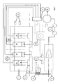
- Figure 1 schematically shows a hybrid propulsion system, particularly for motor vehicles, which comprises an internal-combustion engine 2a of the reciprocating type, typically an Otto or diesel engine, having a number N of cylinders 31, 32 and a number N of pistons 41, 42.
- an internal-combustion engine 2a of the reciprocating type typically an Otto or diesel engine, having a number N of cylinders 31, 32 and a number N of pistons 41, 42.
- a compressed-air engine 2b of the reciprocating type is further provided, which has a number C of cylinders 33, 34 and a number C of pistons 43, 44.
- the compressed-air engine 2b is fed with an air flow at a pressure in a range from 0.5 to 200 bar, directly delivered from the compressor through a pulsation dampening tank 8.
- two cylinders 31, 32 act as combustion chambers and two cylinders 33, 34 act as expansion chambers for compressed air; other solutions may be obviously provided.
- the pistons 41, 42 of the internal-combustion engine 2a and the pistons 43, 44 of the compressed-air engine 2b are connected by a drive shaft 5 by crank gears (not shown).
- the compressed air required to feed the compressed-air engine 2b is thus generated by the internal-combustion engine 2a.
- the cylinders 31, 32 of the internal-combustion engine 2a and the cylinders 33, 34 of the compressed-air engine 2b are formed into a single cylinder block, and the drive shaft 5 is a single crank shaft.
- This solution is also preferred in that it allows the hybrid propulsion system to be obtained from a traditional internal-combustion engine, thereby limiting costs and sizes.
- the high-pressure air generated in real time by the compressor may be injected at temperatures as high as 150/200°C.
- the heat generated by the internal-combustion engine 2a heats air during expansion in the cylinders 33, 34 of the internal-combustion engine, which would otherwise tend to be cooled.
- the cylinders of the compressed-air engine may be alternated between the cylinders of the internal-combustion engine.
- the inventor also suggests that the heat flow from the cylinders 31, 32 of the internal-combustion engine 2a, to the cylinders 33, 34 of the compressed-air engine 2b may allow recovery and conversion of part of the heat energy released by the internal-combustion engine 2a, which would be otherwise inevitably lost.
- the cylinders 33, 34 of the compressed-air engine 2b are directly fed with a compressed air flow generated by an air compressor 6.
- the energy for actuating the air compressor 6 is directly taken up from the drive shaft 5.
- the energy for actuating the air compressor 6 is directly taken up from the drive shaft 5.
- the air compressor 6 may be actuated by an electric motor, such as a battery-operated electric motor, whose battery is recharged by an alternator actuated by the drive shaft 5.
- an electric motor such as a battery-operated electric motor, whose battery is recharged by an alternator actuated by the drive shaft 5.
- a compressed-air distributor 7 is provided for sequentially distributing the compressed air flow to the cylinders 33, 34 of the compressed-air engine 2b.
- the internal-combustion engine 2a is a four-stroke engine, i.e. with a cycle completed in four strokes of the pistons 41, 42, whereas the cycle of the compressed-air engine is completed in two piston strokes.
- a tank 8 is also preferably provided, downstream from the air compressor 6 and upstream from the compressed-air distributor 7, for accumulating the pressurized air delivered by the compressor 6 and dampening pulsations and pressure variations of compressed air.
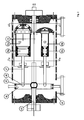
- the air compressor 6 is a positive-displacement compressor of the type having axial pistons driven by a tilting rotary table 66.
- the flow rate and pressure of the outflowing compressed air may be adjusted.
- a stationary body 61 accommodates a driving shaft 62 and a rotor 63 integral with the driving shaft 62, in which four cylindrical chambers 64a, 64b, 64c, 65d are formed with an axis substantially parallel to the axis of rotation of the driving shaft 62.
- axial pistons 65a, 65b, 65c, 65d are housed in the four cylindrical chambers 64a, 64b, 64c, 64d, with one end abutting against a tilting table 66.
- the axial pistons 65a, 65b, 65c, 65d are connected to the tilting table 66 by means of pins 67 that terminate in a ball joint 68 held within a seat 69 formed in the tilting table 66.
- the rotation of the driving shaft 62 and the integral rotor 63 causes the reciprocating motion of the pistons 65a, 65b, 65c, 65d within their cylinders, thereby causing the intake and exhaust operation.
- a peculiarity of the illustrated compressor is that the cylindrical chambers 64a,64b, 64c, 64d are of different sections (and volumes) and are connected in series with progressive volumes from the chamber with the maximum volume 64a to the chamber with the minimum volume 64d.
- air is compressed progressively, in four successive steps, and reaches pressures in a range of 0.5-200 bar.
- the embodiment of the figures includes an electronic control unit 10 which detects the operating state of the internal-combustion engine 2a and the compressed-air engine 2b (temperature, pressure, number of revolutions, etc.) to control the operation of the hybrid propulsion system and optimize consumption, torque, power and response.
- the operating state of the internal-combustion engine 2a and the compressed-air engine 2b temperature, pressure, number of revolutions, etc.
- the electronic control unit 10 adjusts the tilt of the rotary table 66 of the compressor 6, to regulate the power of the compressed air delivered by the air compressor 6 as needed.
Landscapes
- Engineering & Computer Science (AREA)
- Mechanical Engineering (AREA)
- Chemical & Material Sciences (AREA)
- Combustion & Propulsion (AREA)
- General Engineering & Computer Science (AREA)
- Transportation (AREA)
- Hybrid Electric Vehicles (AREA)
- Arrangement Or Mounting Of Propulsion Units For Vehicles (AREA)
- Compressors, Vaccum Pumps And Other Relevant Systems (AREA)
Abstract
A hybrid propulsion system is herein disclosed, particularly for motor vehicles and boats, comprising: an internal-combustion engine (2a) of the reciprocating type, having a number N of cylinders (31, 32) and a number N of pistons (41, 42); a compressed-air engine (2b) of the reciprocating type, having a number C of cylinders (33, 34) and a number C of pistons (43, 44); said compressed-air engine (2b) being in thermal connection with said internal-combustion engine (2a); a drive shaft (5), having said N pistons (41, 42) of said internal-combustion engine (2a) and said C pistons (43, 44) of said compressed-air engine (2b) connected thereto; an air compressor (6) adapted to generate a compressed air flow to be fed to said C cylinders (33, 34) of said compressed-air motor (2b), wherein said internal-combustion engine (2a) and said compressed-air engine (2b) are designed for simultaneous operation.
Description
- A hybrid propulsion system is herein disclosed, particularly for use in the automotive (for motor vehicles, trucks, buses, etc) and naval industries.
- The use of internal-combustion engines in the field of transportation has been known for over a century.
- In spite of the remarkable improvements that have been made over the years, internal-combustion engines still suffer from various drawbacks and cause a number of problems.
- For example, exhaust gases of internal-combustion engines are one of the main sources of atmospheric pollution.
- Several solutions have been proposed to obviate this problem.
- For instance,
DE 10 2005 022 961 B4 (Hentschel - Compressed air may be obtained and compressed in multiple tanks through recovery of kinetic energy during deceleration.
- For an internal-combustion engine to be adapted for operation as a compressed-air engine, Hentschel suggests of modifying the engine head, particularly by adding a compressed air inlet valve, and a heat exchanger to prevent the formation of ice.
- This obviously increases engine manufacturing costs.
- The object of this invention is to obviate at least some of the drawbacks of prior art internal-combustion engines and hybrid engines.
- Particularly, one object of the inventor is to provide a solution to reduce the polluting emissions of internal-combustion engines.
- Another object is to provide a propulsion system that can be manufactured with low investment costs.
- Yet another object is to provide a solution that can improve energy efficiency.
- The objects of the inventor are fulfilled by propulsion system as defined in claim 1.
- Further advantages may be obtained by the additional features of the dependent claims.
- A possible embodiment of the invention will be now described with reference to the accompanying drawings in which:
-
Figure 1 is a schematic view of a hybrid propulsion system; -
Figure 2 is a longitudinal sectional view of an air compressor as used in the propulsion system ofFigure 1 ; -
Figure 3 is a cross sectional view of the compressor of ofFigure 2 . - Referring to the accompanying drawings,
Figure 1 schematically shows a hybrid propulsion system, particularly for motor vehicles, which comprises an internal-combustion engine 2a of the reciprocating type, typically an Otto or diesel engine, having a number N ofcylinders 31, 32 and a number N of pistons 41, 42. - A compressed-air engine 2b of the reciprocating type is further provided, which has a number C of
cylinders pistons - Preferably, the compressed-air engine 2b is fed with an air flow at a pressure in a range from 0.5 to 200 bar, directly delivered from the compressor through a pulsation dampening tank 8.
- In the embodiment as shown herein, two
cylinders 31, 32 act as combustion chambers and twocylinders - The pistons 41, 42 of the internal-combustion engine 2a and the
pistons drive shaft 5 by crank gears (not shown). - The compressed air required to feed the compressed-air engine 2b is thus generated by the internal-combustion engine 2a.
- In one possible embodiment, the
cylinders 31, 32 of the internal-combustion engine 2a and thecylinders drive shaft 5 is a single crank shaft. - This solution is also preferred in that it allows the hybrid propulsion system to be obtained from a traditional internal-combustion engine, thereby limiting costs and sizes.
- Any reader skilled in the art will appreciate that this solution allows the engine to be used as an internal-combustion engine and as a compressed-air engine at the same time, without making any change to the head.
- Furthermore, this allows the compressed-air engine 2b to be in thermal connection with the internal-combustion engine 2a.
- The high-pressure air generated in real time by the compressor may be injected at temperatures as high as 150/200°C.
- Due to this feature, the heat generated by the internal-combustion engine 2a heats air during expansion in the
cylinders - This prevents the formation of ice in the engine, as well as any risk of obstruction of the compressed air flow caused by such formation of ice.
- While the inventor does not intend to provide any scientific explanation, he nevertheless also believes that, due to the heat received from the
cylinders 31, 32 of the internal-combustion engine 2a and to the direct injection of air heated by the compression cycle of the compressor, air is expanded within thecylinders - In order to improve heat transfer between the
cylinders 31, 32 of the internal-combustion engine 2a and the cylinders of the compressed-air engine 2b, the cylinders of the compressed-air engine may be alternated between the cylinders of the internal-combustion engine. - The inventor also suggests that the heat flow from the
cylinders 31, 32 of the internal-combustion engine 2a, to thecylinders - The
cylinders - In the embodiment of the figures, the energy for actuating the air compressor 6 is directly taken up from the
drive shaft 5. - This solution is preferred because it limits the costs and sizes of the propulsion system.
- In the embodiment of the figures, the energy for actuating the air compressor 6 is directly taken up from the
drive shaft 5. - Alternatively, the air compressor 6 may be actuated by an electric motor, such as a battery-operated electric motor, whose battery is recharged by an alternator actuated by the
drive shaft 5. - If the number C of
cylinders cylinders - In the preferred embodiment, the internal-combustion engine 2a is a four-stroke engine, i.e. with a cycle completed in four strokes of the pistons 41, 42, whereas the cycle of the compressed-air engine is completed in two piston strokes.
- A tank 8 is also preferably provided, downstream from the air compressor 6 and upstream from the compressed-air distributor 7, for accumulating the pressurized air delivered by the compressor 6 and dampening pulsations and pressure variations of compressed air.
- In one embodiment, the air compressor 6 is a positive-displacement compressor of the type having axial pistons driven by a tilting rotary table 66.
- By changing the tilt of the rotary table 66, the flow rate and pressure of the outflowing compressed air may be adjusted.
- A
stationary body 61 accommodates adriving shaft 62 and arotor 63 integral with thedriving shaft 62, in which fourcylindrical chambers driving shaft 62. - Four
axial pistons cylindrical chambers - The
axial pistons pins 67 that terminate in aball joint 68 held within aseat 69 formed in the tilting table 66. - The rotation of the
driving shaft 62 and theintegral rotor 63 causes the reciprocating motion of thepistons - A peculiarity of the illustrated compressor is that the
cylindrical chambers maximum volume 64a to the chamber with the minimum volume 64d. - Thus, air is compressed progressively, in four successive steps, and reaches pressures in a range of 0.5-200 bar.
- The embodiment of the figures includes an
electronic control unit 10 which detects the operating state of the internal-combustion engine 2a and the compressed-air engine 2b (temperature, pressure, number of revolutions, etc.) to control the operation of the hybrid propulsion system and optimize consumption, torque, power and response. - Particularly, the
electronic control unit 10 adjusts the tilt of the rotary table 66 of the compressor 6, to regulate the power of the compressed air delivered by the air compressor 6 as needed.
Claims (7)
- A hybrid propulsion system, particularly for motor vehicles and boats, comprising- an internal-combustion engine (2a) of the reciprocating type, having a number N of cylinders (31, 32) and a number N of pistons (41, 42);- a compressed-air engine (2b) of the reciprocating type, having a number C of cylinders (33, 34) and a number C of pistons (43, 44);- said compressed-air engine (2b) being in thermal connection with said internal-combustion engine (2a);- a drive shaft (5), having said N pistons (41, 42) of said internal-combustion engine (2a) and said C pistons (43, 44) of said compressed-air engine (2b) connected thereto;- an air compressor (6) adapted to generate a compressed air flow to be fed to said C cylinders (33, 34) of said compressed-air motor (2b).wherein said internal-combustion engine (2a) and said compressed-air engine (2b) are designed for simultaneous operation.
- A hybrid propulsion system as claimed in claim 1, wherein said air compressor (6) is directly driven by said drive shaft (5).
- A hybrid propulsion system as claimed in claim 1 or 2, wherein the number C of cylinders (33, 34) of said compressed-air engine (2b) is equal to or greater than 2 and wherein a compressed-air distributor (7) is provided for sequentially distributing said compressed air flow to said cylinders (33, 34) of said compressed-air engine (2b).
- A hybrid propulsion system as claimed in any preceding claim, wherein a tank (8) is provided downstream from said air compressor (6) for storing pressurized air.
- A hybrid propulsion system as claimed in any claim from 2 to 4, wherein said air compressor (6) is connected to said shaft (5) via a rev limiter (9).
- A hybrid propulsion system as claimed in any preceding claim, wherein said air compressor (6) is a positive-displacement compressor of the type having axial pistons (65a, 65b, 65c, 65d ) driven by a tilting rotary table (66).
- A hybrid propulsion system as claimed in claim 6, wherein said positive-displacement compressor (6) comprises chambers (64a, 64b, 64c, 64d) of different sections, said chambers (64a, 64b, 64c, 64d) being connected in series with progressive volumes from the chamber with the largest volume (64a) to the chamber with the smallest volume (64d).
Applications Claiming Priority (1)
| Application Number | Priority Date | Filing Date | Title |
|---|---|---|---|
| ITMI2009A000040A IT1397616B1 (en) | 2009-01-19 | 2009-01-19 | HYBRID PROPULSION SYSTEM, IN PARTICULAR FOR MOTOR VEHICLES AND BOATS. |
Publications (1)
| Publication Number | Publication Date |
|---|---|
| EP2210759A1 true EP2210759A1 (en) | 2010-07-28 |
Family
ID=41008913
Family Applications (1)
| Application Number | Title | Priority Date | Filing Date |
|---|---|---|---|
| EP10150407A Withdrawn EP2210759A1 (en) | 2009-01-19 | 2010-01-11 | Hybrid propulsion system, particularly for motor vehicles and boats |
Country Status (2)
| Country | Link |
|---|---|
| EP (1) | EP2210759A1 (en) |
| IT (1) | IT1397616B1 (en) |
Cited By (1)
| Publication number | Priority date | Publication date | Assignee | Title |
|---|---|---|---|---|
| WO2026076506A1 (en) * | 2024-10-09 | 2026-04-16 | Dariva Antonio | Hybrid air engine with a combined cycle |
Citations (5)
| Publication number | Priority date | Publication date | Assignee | Title |
|---|---|---|---|---|
| US4496291A (en) * | 1981-11-13 | 1985-01-29 | Grimmer John E | Compound turbocharger system for an internal combustion engine |
| EP1176309A2 (en) * | 2000-07-28 | 2002-01-30 | SANYO ELECTRIC Co., Ltd. | Reciprocating compressor |
| US20060021813A1 (en) * | 2000-01-10 | 2006-02-02 | Gov. Of The U.S.A, As Rep. By The Administrator Of The U.S. Environmental Protection Agency | Independent displacement opposing pump/motors and method of operation |
| DE102005022961A1 (en) * | 2005-05-19 | 2006-11-23 | Andreas Hentschel | Bivalent process to operate piston engine using conventional liquid fuel aided by compressed air and exhaust gas heat recovery |
| US7231998B1 (en) * | 2004-04-09 | 2007-06-19 | Michael Moses Schechter | Operating a vehicle with braking energy recovery |
-
2009
- 2009-01-19 IT ITMI2009A000040A patent/IT1397616B1/en active
-
2010
- 2010-01-11 EP EP10150407A patent/EP2210759A1/en not_active Withdrawn
Patent Citations (6)
| Publication number | Priority date | Publication date | Assignee | Title |
|---|---|---|---|---|
| US4496291A (en) * | 1981-11-13 | 1985-01-29 | Grimmer John E | Compound turbocharger system for an internal combustion engine |
| US20060021813A1 (en) * | 2000-01-10 | 2006-02-02 | Gov. Of The U.S.A, As Rep. By The Administrator Of The U.S. Environmental Protection Agency | Independent displacement opposing pump/motors and method of operation |
| EP1176309A2 (en) * | 2000-07-28 | 2002-01-30 | SANYO ELECTRIC Co., Ltd. | Reciprocating compressor |
| US7231998B1 (en) * | 2004-04-09 | 2007-06-19 | Michael Moses Schechter | Operating a vehicle with braking energy recovery |
| DE102005022961A1 (en) * | 2005-05-19 | 2006-11-23 | Andreas Hentschel | Bivalent process to operate piston engine using conventional liquid fuel aided by compressed air and exhaust gas heat recovery |
| DE102005022961B4 (en) | 2005-05-19 | 2007-04-19 | Andreas Hentschel | Method for bivalent operation of internal combustion engines with conventional fuels and compressed gas |
Cited By (1)
| Publication number | Priority date | Publication date | Assignee | Title |
|---|---|---|---|---|
| WO2026076506A1 (en) * | 2024-10-09 | 2026-04-16 | Dariva Antonio | Hybrid air engine with a combined cycle |
Also Published As
| Publication number | Publication date |
|---|---|
| ITMI20090040A1 (en) | 2010-07-20 |
| IT1397616B1 (en) | 2013-01-18 |
Similar Documents
| Publication | Publication Date | Title |
|---|---|---|
| US9046054B2 (en) | Heat engine with external hot source | |
| EP2406479B1 (en) | Dual fuel compression ignition engines and methods | |
| US9074526B2 (en) | Split cycle engine and method with increased power density | |
| RU2622457C1 (en) | Internal combustion engine based on isothermal compression, its operating and management methods | |
| US8499728B2 (en) | Cylinder linkage method for a multi-cylinder internal-combustion engine and a multicylinder linkage compound internalcombustion engine | |
| KR20090045286A (en) | Six cycle engine with regenerative machine | |
| US9074588B2 (en) | Air compression method and apparatus | |
| RU2638901C2 (en) | Supercharged internal combustion engine and method of operation of supercharged internal combustion engine | |
| US11512654B2 (en) | Method for controlling injection in a combustion engine | |
| EP2210759A1 (en) | Hybrid propulsion system, particularly for motor vehicles and boats | |
| CN101413424A (en) | Middle cold back heating internal combustion engine with four-stroke engine as main body | |
| US20150308296A1 (en) | Volumetric fluid expander with water injection | |
| US20140250876A1 (en) | Method and apparatus for operating an engine on natural air | |
| US9803541B2 (en) | Internal combustion engine | |
| CN111120090B (en) | Energy storage power device | |
| US10871105B1 (en) | Rotating internal combustion engine | |
| CN216008677U (en) | Compression ignition engine and vehicle | |
| WO1999030017A1 (en) | Internal combustion engine | |
| US20180016980A1 (en) | Modular complex for production of effective power through combustion of liquid and gaseous fuels | |
| JP2022080290A (en) | Internal combustion engine and vehicle | |
| US20040163794A1 (en) | Engine driven by high-pressure gas | |
| WO2026048100A1 (en) | Internal combustion engine system, vehicle equipped with internal combustion engine system, and method for controlling fuel supply device | |
| JP2026043791A (en) | Internal combustion engine system, vehicle equipped with an internal combustion engine system, method for controlling an internal combustion engine system | |
| WO2004001206A1 (en) | Internal-combustion engine with separate and optimized compression, combustion and expansion stroke | |
| WO2008026955A2 (en) | A method for generation of mechanical energy by means of internal combustion traction |
Legal Events
| Date | Code | Title | Description |
|---|---|---|---|
| PUAI | Public reference made under article 153(3) epc to a published international application that has entered the european phase |
Free format text: ORIGINAL CODE: 0009012 |
|
| AK | Designated contracting states |
Kind code of ref document: A1 Designated state(s): AT BE BG CH CY CZ DE DK EE ES FI FR GB GR HR HU IE IS IT LI LT LU LV MC MK MT NL NO PL PT RO SE SI SK SM TR |
|
| AX | Request for extension of the european patent |
Extension state: AL BA RS |
|
| 17P | Request for examination filed |
Effective date: 20101119 |
|
| RIN1 | Information on inventor provided before grant (corrected) |
Inventor name: MAZZOTTA, GIOVANNI |
|
| STAA | Information on the status of an ep patent application or granted ep patent |
Free format text: STATUS: THE APPLICATION IS DEEMED TO BE WITHDRAWN |
|
| 18D | Application deemed to be withdrawn |
Effective date: 20140801 |