EP2210626B1 - Medical devices having drugs adhered to the surface thereof. - Google Patents
Medical devices having drugs adhered to the surface thereof. Download PDFInfo
- Publication number
- EP2210626B1 EP2210626B1 EP10158600.6A EP10158600A EP2210626B1 EP 2210626 B1 EP2210626 B1 EP 2210626B1 EP 10158600 A EP10158600 A EP 10158600A EP 2210626 B1 EP2210626 B1 EP 2210626B1
- Authority
- EP
- European Patent Office
- Prior art keywords
- drug
- medical device
- stent
- gcib
- irradiated
- Prior art date
- Legal status (The legal status is an assumption and is not a legal conclusion. Google has not performed a legal analysis and makes no representation as to the accuracy of the status listed.)
- Expired - Lifetime
Links
- 239000003814 drug Substances 0.000 title claims description 63
- 229940079593 drug Drugs 0.000 title claims description 52
- 238000010884 ion-beam technique Methods 0.000 claims description 24
- 239000000463 material Substances 0.000 claims description 13
- 239000011159 matrix material Substances 0.000 claims description 9
- 229920000642 polymer Polymers 0.000 claims description 8
- 239000002184 metal Substances 0.000 claims description 7
- 239000003146 anticoagulant agent Substances 0.000 claims description 6
- 238000000576 coating method Methods 0.000 claims description 6
- 239000000126 substance Substances 0.000 claims description 6
- OKTJSMMVPCPJKN-UHFFFAOYSA-N Carbon Chemical compound [C] OKTJSMMVPCPJKN-UHFFFAOYSA-N 0.000 claims description 5
- 210000004204 blood vessel Anatomy 0.000 claims description 5
- 229910052799 carbon Inorganic materials 0.000 claims description 5
- 239000011248 coating agent Substances 0.000 claims description 5
- HVYWMOMLDIMFJA-DPAQBDIFSA-N cholesterol Chemical compound C1C=C2C[C@@H](O)CC[C@]2(C)[C@@H]2[C@@H]1[C@@H]1CC[C@H]([C@H](C)CCCC(C)C)[C@@]1(C)CC2 HVYWMOMLDIMFJA-DPAQBDIFSA-N 0.000 claims description 4
- -1 polyethylene Polymers 0.000 claims description 4
- 239000004698 Polyethylene Substances 0.000 claims description 2
- 239000003242 anti bacterial agent Substances 0.000 claims description 2
- 230000000702 anti-platelet effect Effects 0.000 claims description 2
- 230000002785 anti-thrombosis Effects 0.000 claims description 2
- 229940088710 antibiotic agent Drugs 0.000 claims description 2
- 229940127219 anticoagulant drug Drugs 0.000 claims description 2
- 239000011230 binding agent Substances 0.000 claims description 2
- 239000000919 ceramic Substances 0.000 claims description 2
- 239000003638 chemical reducing agent Substances 0.000 claims description 2
- 239000003795 chemical substances by application Substances 0.000 claims description 2
- 235000012000 cholesterol Nutrition 0.000 claims description 2
- 229920000573 polyethylene Polymers 0.000 claims description 2
- 229940124549 vasodilator Drugs 0.000 claims description 2
- 239000003071 vasodilator agent Substances 0.000 claims description 2
- 238000012377 drug delivery Methods 0.000 claims 2
- 239000007789 gas Substances 0.000 description 29
- 238000000034 method Methods 0.000 description 20
- 150000002500 ions Chemical class 0.000 description 18
- 238000012545 processing Methods 0.000 description 17
- 239000000178 monomer Substances 0.000 description 14
- 208000037803 restenosis Diseases 0.000 description 11
- 239000010410 layer Substances 0.000 description 8
- 238000005516 engineering process Methods 0.000 description 7
- XKRFYHLGVUSROY-UHFFFAOYSA-N Argon Chemical compound [Ar] XKRFYHLGVUSROY-UHFFFAOYSA-N 0.000 description 6
- 238000002399 angioplasty Methods 0.000 description 6
- 210000001519 tissue Anatomy 0.000 description 6
- 238000002513 implantation Methods 0.000 description 5
- 239000007788 liquid Substances 0.000 description 5
- 229940124597 therapeutic agent Drugs 0.000 description 5
- 208000007536 Thrombosis Diseases 0.000 description 4
- 210000001367 artery Anatomy 0.000 description 4
- 239000007943 implant Substances 0.000 description 4
- 230000004048 modification Effects 0.000 description 4
- 238000012986 modification Methods 0.000 description 4
- 230000008569 process Effects 0.000 description 4
- 229910052786 argon Inorganic materials 0.000 description 3
- 238000000089 atomic force micrograph Methods 0.000 description 3
- 230000008901 benefit Effects 0.000 description 3
- 230000000975 bioactive effect Effects 0.000 description 3
- 230000004663 cell proliferation Effects 0.000 description 3
- 230000000694 effects Effects 0.000 description 3
- 238000004519 manufacturing process Methods 0.000 description 3
- 239000003504 photosensitizing agent Substances 0.000 description 3
- 230000004044 response Effects 0.000 description 3
- 239000002904 solvent Substances 0.000 description 3
- IJGRMHOSHXDMSA-UHFFFAOYSA-N Atomic nitrogen Chemical compound N#N IJGRMHOSHXDMSA-UHFFFAOYSA-N 0.000 description 2
- CURLTUGMZLYLDI-UHFFFAOYSA-N Carbon dioxide Chemical compound O=C=O CURLTUGMZLYLDI-UHFFFAOYSA-N 0.000 description 2
- 230000001133 acceleration Effects 0.000 description 2
- WTEOIRVLGSZEPR-UHFFFAOYSA-N boron trifluoride Chemical compound FB(F)F WTEOIRVLGSZEPR-UHFFFAOYSA-N 0.000 description 2
- 239000000356 contaminant Substances 0.000 description 2
- 230000001186 cumulative effect Effects 0.000 description 2
- 238000000151 deposition Methods 0.000 description 2
- 230000008021 deposition Effects 0.000 description 2
- 238000013461 design Methods 0.000 description 2
- 238000007598 dipping method Methods 0.000 description 2
- 238000010828 elution Methods 0.000 description 2
- 238000000605 extraction Methods 0.000 description 2
- 238000009499 grossing Methods 0.000 description 2
- 230000035876 healing Effects 0.000 description 2
- 238000003780 insertion Methods 0.000 description 2
- 230000037431 insertion Effects 0.000 description 2
- 238000005468 ion implantation Methods 0.000 description 2
- 238000011068 loading method Methods 0.000 description 2
- 230000007246 mechanism Effects 0.000 description 2
- 230000035515 penetration Effects 0.000 description 2
- 229920000052 poly(p-xylylene) Polymers 0.000 description 2
- 239000000843 powder Substances 0.000 description 2
- 230000002285 radioactive effect Effects 0.000 description 2
- 238000009877 rendering Methods 0.000 description 2
- 231100000241 scar Toxicity 0.000 description 2
- 210000000329 smooth muscle myocyte Anatomy 0.000 description 2
- 241000894007 species Species 0.000 description 2
- 238000005507 spraying Methods 0.000 description 2
- 238000004544 sputter deposition Methods 0.000 description 2
- 230000003746 surface roughness Effects 0.000 description 2
- 210000005166 vasculature Anatomy 0.000 description 2
- 206010003211 Arteriosclerosis coronary artery Diseases 0.000 description 1
- 208000037260 Atherosclerotic Plaque Diseases 0.000 description 1
- 229910015900 BF3 Inorganic materials 0.000 description 1
- 239000004971 Cross linker Substances 0.000 description 1
- IAYPIBMASNFSPL-UHFFFAOYSA-N Ethylene oxide Chemical compound C1CO1 IAYPIBMASNFSPL-UHFFFAOYSA-N 0.000 description 1
- 102000008946 Fibrinogen Human genes 0.000 description 1
- 108010049003 Fibrinogen Proteins 0.000 description 1
- 241000124008 Mammalia Species 0.000 description 1
- 208000031481 Pathologic Constriction Diseases 0.000 description 1
- 239000004952 Polyamide Substances 0.000 description 1
- 230000002159 abnormal effect Effects 0.000 description 1
- 238000004458 analytical method Methods 0.000 description 1
- QVGXLLKOCUKJST-UHFFFAOYSA-N atomic oxygen Chemical compound [O] QVGXLLKOCUKJST-UHFFFAOYSA-N 0.000 description 1
- 210000003445 biliary tract Anatomy 0.000 description 1
- 230000015572 biosynthetic process Effects 0.000 description 1
- 230000023555 blood coagulation Effects 0.000 description 1
- 229910052796 boron Inorganic materials 0.000 description 1
- 239000001569 carbon dioxide Substances 0.000 description 1
- 229910002092 carbon dioxide Inorganic materials 0.000 description 1
- 210000000748 cardiovascular system Anatomy 0.000 description 1
- 229940000032 cardiovascular system drug Drugs 0.000 description 1
- 239000003054 catalyst Substances 0.000 description 1
- 230000010261 cell growth Effects 0.000 description 1
- 230000006037 cell lysis Effects 0.000 description 1
- 230000001413 cellular effect Effects 0.000 description 1
- 230000008859 change Effects 0.000 description 1
- 230000002925 chemical effect Effects 0.000 description 1
- 238000006243 chemical reaction Methods 0.000 description 1
- 238000004140 cleaning Methods 0.000 description 1
- 239000008199 coating composition Substances 0.000 description 1
- 210000001072 colon Anatomy 0.000 description 1
- 238000009833 condensation Methods 0.000 description 1
- 230000005494 condensation Effects 0.000 description 1
- 239000000470 constituent Substances 0.000 description 1
- 238000013270 controlled release Methods 0.000 description 1
- 238000001816 cooling Methods 0.000 description 1
- 208000029078 coronary artery disease Diseases 0.000 description 1
- 208000026758 coronary atherosclerosis Diseases 0.000 description 1
- 210000004351 coronary vessel Anatomy 0.000 description 1
- 230000000875 corresponding effect Effects 0.000 description 1
- 230000003247 decreasing effect Effects 0.000 description 1
- 230000001627 detrimental effect Effects 0.000 description 1
- 238000009826 distribution Methods 0.000 description 1
- 238000001312 dry etching Methods 0.000 description 1
- 230000002526 effect on cardiovascular system Effects 0.000 description 1
- 238000010894 electron beam technology Methods 0.000 description 1
- 230000003511 endothelial effect Effects 0.000 description 1
- 239000000284 extract Substances 0.000 description 1
- 229940012952 fibrinogen Drugs 0.000 description 1
- 230000003116 impacting effect Effects 0.000 description 1
- 230000006872 improvement Effects 0.000 description 1
- 238000001727 in vivo Methods 0.000 description 1
- 238000011065 in-situ storage Methods 0.000 description 1
- 238000007373 indentation Methods 0.000 description 1
- 208000014674 injury Diseases 0.000 description 1
- 230000003993 interaction Effects 0.000 description 1
- 230000002934 lysing effect Effects 0.000 description 1
- 229910052757 nitrogen Inorganic materials 0.000 description 1
- 238000005457 optimization Methods 0.000 description 1
- 239000001301 oxygen Substances 0.000 description 1
- 229910052760 oxygen Inorganic materials 0.000 description 1
- 239000002245 particle Substances 0.000 description 1
- 230000000149 penetrating effect Effects 0.000 description 1
- 230000000704 physical effect Effects 0.000 description 1
- 239000004033 plastic Substances 0.000 description 1
- 229920003023 plastic Polymers 0.000 description 1
- 238000005498 polishing Methods 0.000 description 1
- 229920002647 polyamide Polymers 0.000 description 1
- 229920001296 polysiloxane Polymers 0.000 description 1
- 239000011148 porous material Substances 0.000 description 1
- 238000002203 pretreatment Methods 0.000 description 1
- 230000001737 promoting effect Effects 0.000 description 1
- 238000005086 pumping Methods 0.000 description 1
- 230000005855 radiation Effects 0.000 description 1
- 230000009467 reduction Effects 0.000 description 1
- 239000004065 semiconductor Substances 0.000 description 1
- 210000002460 smooth muscle Anatomy 0.000 description 1
- 239000011877 solvent mixture Substances 0.000 description 1
- 230000036262 stenosis Effects 0.000 description 1
- 208000037804 stenosis Diseases 0.000 description 1
- 239000000758 substrate Substances 0.000 description 1
- 239000002344 surface layer Substances 0.000 description 1
- 238000004381 surface treatment Methods 0.000 description 1
- 238000002560 therapeutic procedure Methods 0.000 description 1
- 239000010409 thin film Substances 0.000 description 1
- 231100000331 toxic Toxicity 0.000 description 1
- 230000002588 toxic effect Effects 0.000 description 1
- 231100000419 toxicity Toxicity 0.000 description 1
- 230000001988 toxicity Effects 0.000 description 1
- 210000003437 trachea Anatomy 0.000 description 1
- 230000008733 trauma Effects 0.000 description 1
- 210000001635 urinary tract Anatomy 0.000 description 1
- 238000001947 vapour-phase growth Methods 0.000 description 1
- 230000002792 vascular Effects 0.000 description 1
Images


Classifications
-
- C—CHEMISTRY; METALLURGY
- C23—COATING METALLIC MATERIAL; COATING MATERIAL WITH METALLIC MATERIAL; CHEMICAL SURFACE TREATMENT; DIFFUSION TREATMENT OF METALLIC MATERIAL; COATING BY VACUUM EVAPORATION, BY SPUTTERING, BY ION IMPLANTATION OR BY CHEMICAL VAPOUR DEPOSITION, IN GENERAL; INHIBITING CORROSION OF METALLIC MATERIAL OR INCRUSTATION IN GENERAL
- C23C—COATING METALLIC MATERIAL; COATING MATERIAL WITH METALLIC MATERIAL; SURFACE TREATMENT OF METALLIC MATERIAL BY DIFFUSION INTO THE SURFACE, BY CHEMICAL CONVERSION OR SUBSTITUTION; COATING BY VACUUM EVAPORATION, BY SPUTTERING, BY ION IMPLANTATION OR BY CHEMICAL VAPOUR DEPOSITION, IN GENERAL
- C23C14/00—Coating by vacuum evaporation, by sputtering or by ion implantation of the coating forming material
- C23C14/02—Pretreatment of the material to be coated
- C23C14/021—Cleaning or etching treatments
- C23C14/022—Cleaning or etching treatments by means of bombardment with energetic particles or radiation
-
- A—HUMAN NECESSITIES
- A61—MEDICAL OR VETERINARY SCIENCE; HYGIENE
- A61L—METHODS OR APPARATUS FOR STERILISING MATERIALS OR OBJECTS IN GENERAL; DISINFECTION, STERILISATION OR DEODORISATION OF AIR; CHEMICAL ASPECTS OF BANDAGES, DRESSINGS, ABSORBENT PADS OR SURGICAL ARTICLES; MATERIALS FOR BANDAGES, DRESSINGS, ABSORBENT PADS OR SURGICAL ARTICLES
- A61L31/00—Materials for other surgical articles, e.g. stents, stent-grafts, shunts, surgical drapes, guide wires, materials for adhesion prevention, occluding devices, surgical gloves, tissue fixation devices
- A61L31/14—Materials characterised by their function or physical properties, e.g. injectable or lubricating compositions, shape-memory materials, surface modified materials
-
- A—HUMAN NECESSITIES
- A61—MEDICAL OR VETERINARY SCIENCE; HYGIENE
- A61L—METHODS OR APPARATUS FOR STERILISING MATERIALS OR OBJECTS IN GENERAL; DISINFECTION, STERILISATION OR DEODORISATION OF AIR; CHEMICAL ASPECTS OF BANDAGES, DRESSINGS, ABSORBENT PADS OR SURGICAL ARTICLES; MATERIALS FOR BANDAGES, DRESSINGS, ABSORBENT PADS OR SURGICAL ARTICLES
- A61L31/00—Materials for other surgical articles, e.g. stents, stent-grafts, shunts, surgical drapes, guide wires, materials for adhesion prevention, occluding devices, surgical gloves, tissue fixation devices
- A61L31/14—Materials characterised by their function or physical properties, e.g. injectable or lubricating compositions, shape-memory materials, surface modified materials
- A61L31/16—Biologically active materials, e.g. therapeutic substances
-
- C—CHEMISTRY; METALLURGY
- C23—COATING METALLIC MATERIAL; COATING MATERIAL WITH METALLIC MATERIAL; CHEMICAL SURFACE TREATMENT; DIFFUSION TREATMENT OF METALLIC MATERIAL; COATING BY VACUUM EVAPORATION, BY SPUTTERING, BY ION IMPLANTATION OR BY CHEMICAL VAPOUR DEPOSITION, IN GENERAL; INHIBITING CORROSION OF METALLIC MATERIAL OR INCRUSTATION IN GENERAL
- C23C—COATING METALLIC MATERIAL; COATING MATERIAL WITH METALLIC MATERIAL; SURFACE TREATMENT OF METALLIC MATERIAL BY DIFFUSION INTO THE SURFACE, BY CHEMICAL CONVERSION OR SUBSTITUTION; COATING BY VACUUM EVAPORATION, BY SPUTTERING, BY ION IMPLANTATION OR BY CHEMICAL VAPOUR DEPOSITION, IN GENERAL
- C23C14/00—Coating by vacuum evaporation, by sputtering or by ion implantation of the coating forming material
- C23C14/22—Coating by vacuum evaporation, by sputtering or by ion implantation of the coating forming material characterised by the process of coating
- C23C14/221—Ion beam deposition
-
- C—CHEMISTRY; METALLURGY
- C23—COATING METALLIC MATERIAL; COATING MATERIAL WITH METALLIC MATERIAL; CHEMICAL SURFACE TREATMENT; DIFFUSION TREATMENT OF METALLIC MATERIAL; COATING BY VACUUM EVAPORATION, BY SPUTTERING, BY ION IMPLANTATION OR BY CHEMICAL VAPOUR DEPOSITION, IN GENERAL; INHIBITING CORROSION OF METALLIC MATERIAL OR INCRUSTATION IN GENERAL
- C23C—COATING METALLIC MATERIAL; COATING MATERIAL WITH METALLIC MATERIAL; SURFACE TREATMENT OF METALLIC MATERIAL BY DIFFUSION INTO THE SURFACE, BY CHEMICAL CONVERSION OR SUBSTITUTION; COATING BY VACUUM EVAPORATION, BY SPUTTERING, BY ION IMPLANTATION OR BY CHEMICAL VAPOUR DEPOSITION, IN GENERAL
- C23C14/00—Coating by vacuum evaporation, by sputtering or by ion implantation of the coating forming material
- C23C14/22—Coating by vacuum evaporation, by sputtering or by ion implantation of the coating forming material characterised by the process of coating
- C23C14/50—Substrate holders
- C23C14/505—Substrate holders for rotation of the substrates
-
- A—HUMAN NECESSITIES
- A61—MEDICAL OR VETERINARY SCIENCE; HYGIENE
- A61F—FILTERS IMPLANTABLE INTO BLOOD VESSELS; PROSTHESES; DEVICES PROVIDING PATENCY TO, OR PREVENTING COLLAPSING OF, TUBULAR STRUCTURES OF THE BODY, e.g. STENTS; ORTHOPAEDIC, NURSING OR CONTRACEPTIVE DEVICES; FOMENTATION; TREATMENT OR PROTECTION OF EYES OR EARS; BANDAGES, DRESSINGS OR ABSORBENT PADS; FIRST-AID KITS
- A61F2/00—Filters implantable into blood vessels; Prostheses, i.e. artificial substitutes or replacements for parts of the body; Appliances for connecting them with the body; Devices providing patency to, or preventing collapsing of, tubular structures of the body, e.g. stents
- A61F2/82—Devices providing patency to, or preventing collapsing of, tubular structures of the body, e.g. stents
- A61F2/86—Stents in a form characterised by the wire-like elements; Stents in the form characterised by a net-like or mesh-like structure
-
- A—HUMAN NECESSITIES
- A61—MEDICAL OR VETERINARY SCIENCE; HYGIENE
- A61L—METHODS OR APPARATUS FOR STERILISING MATERIALS OR OBJECTS IN GENERAL; DISINFECTION, STERILISATION OR DEODORISATION OF AIR; CHEMICAL ASPECTS OF BANDAGES, DRESSINGS, ABSORBENT PADS OR SURGICAL ARTICLES; MATERIALS FOR BANDAGES, DRESSINGS, ABSORBENT PADS OR SURGICAL ARTICLES
- A61L2300/00—Biologically active materials used in bandages, wound dressings, absorbent pads or medical devices
Definitions
- This invention relates generally to medical devices implantable in a mammal, such as coronary stents and to a method and system for applying and adhering drugs to the surface of medical devices using gas cluster ion beam technology and/or monomer ion beam technology.
- the invention can also be used with implantable prostheses,
- a coronary stent is an implantable medical device that is used in combination with balloon angioplasty.
- Balloon angioplasty is a procedure used to treat coronary atherosclerosis. Balloon angioplasty compresses built-up plaque against the walls of the blocked artery by the inflation of a balloon at the tip of a catheter inserted into the artery during the angioplasty procedure, Unfortunately, the body's response to this procedure often includes thrombosis or blood clotting and the formation of scar tissue or other trauma-induced tissue reactions at the treatment site.
- Statistics show that restenosis or renarrowing of the artery by scar tissue after balloon angioplasty occurs in up to 35 percent of the treated patients within only six months after these procedures, leading to severe complications in many patients.
- a coronary stent To reduce restenosis, cardiologists are now often placing a small metal tubular devices of various forms, such as wire mesh or expandable metal, called a coronary stent at the site of blockage during balloon angioplasty. The goal is to have the stent act as a scaffold to keep the coronary artery open after the removal of the balloon.
- Coronary restenotic complications associated with stents occur in 16 to 22 percent of all cases within six months after insertion of the stent and are believed to be caused by many factors acting alone or in combination. These complications could be reduced by several type of drugs introduced locally at the site of stent implantation. Because of the substantial financial costs associated with treating the complications of restenosis, such as catheterization, restenting, intensive care, etc., a reduction in restenosis rates would save money and reduce patient suffering.
- WO-A-02/083039 discloses a stent of variable surface area as determined by stent struts the stent can have a variable surface area per unit length which accommodates a therapeutic agent. A patterned distribution of therapeutic agent can be provided throughout the stent The stent can have an increased level of therapeutic agent near an end of the stent.
- FEHSENFELD P ET AL "Production of radioactive stents" NACHRICHTEN FORSCHUNGSZENTRUM KARLSRUHE FORSCHUNGSZENTRUM KARLAHE GERMANY, vol. 32. no 1-2, 2000, pages 81-86.
- XP002417713 ISSN: 0948-0919 discloses the production of radioactive stents Different methods of production are considered including a method for ion implantation of the isotope P-32 on to the surface of the stents in order to prevent restenosis.
- EP-A-0 875 218 discloses a medicated prosthesis, such as a stent, to be deployed in a human vessel
- a metallic stent has a plurality of pores in the metal which are loaded with medication.
- the medication in the stent dissipates into the tissue of the vasculature proximate the stent.
- the stent may be formed from a porous metal in the form of a wire, tube, or metal sheet.
- European Patent specification no EP-A-0 747 069 discloses a coated implantable medical device which includes a structure adapted for introduction into the vascular system, oesophagus, trachea, colon, biliary tract, or urinary tract; at least one layer of a bioactive material posited on one surface of structure; and at least one porous layer posited over the bioactive material layer posited on one surface of structure and the bioactive-material-free surface.
- the structure is a coronary stent.
- the porous layer is comprised of a polymer applied preferably by vapour or plasma deposition and provides a controlled release of the bioactive material. It is particularly preferred that the polymer is a polyamide, parylene or a parylene derivative, which is deposited without solvents, heat or catalysts, merely by condensation of a monomer vapour.
- the application of the drug is achieved through the use of GCIB technology and/or monomer ion beam technology
- the application of the drug is accomplished by several methods:
- GCIB gas cluster ion beam
- monomer ion beam surface modification such as described above will reduce complications, lead to genuine cost savings and an improvement in patient quality of life, and overcome prior problems of thrombosis and restenosis.
- gas cluster ion beam (GCIB) processing is utilized.
- Gas cluster ions are formed from large numbers of weakly bound atoms or molecules sharing common electrical charges and accelerated together through high voltages to have high total energies. Cluster ions disintegrate upon impact and the total energy of the cluster is shared among the constituent atoms. Because of this energy sharing, the atoms are individually much less energetic than the case of conventional ions or ions not clustered together and, as a result, the atoms penetrate to much shorter depths.
- Surface sputtering effects are orders of magnitude stronger than corresponding effects produced by conventional ions, thereby making important microscale surface effects possible that are not possible in any other way.
- Patent 5,459,326 that such individual atoms are not energetic enough to significantly penetrate a surface to cause the residual sub-surface damage typically associated with plasma polishing. Nevertheless, the clusters themselves are sufficiently energetic (some thousands of electron volts) to effectively etch, smooth, or clean hard surfaces.
- the energies of individual atoms within a gas cluster ion are very small, typically a few eV, the atoms penetrate through only a few atomic layers, at most, of a target surface during impact.
- This shallow penetration of the impacting atoms means all of the energy carried by the entire cluster ion is consequently dissipated in an extremely small volume in the top surface layer during a period on the order of 10-12 seconds (i.e. one picosecond).
- This is different from the case of ion implantation which is normally done with conventional monomer ions and where the intent is to penetrate into the material, sometimes penetrating several thousand angstroms, to produce changes in the surface properties of the material.
- the deposited energy density at the impact site is far greater than in the case of bombardment by conventional monomer ions.
- the three chambers are evacuated to suitable operating pressures by vacuum pumping systems 146a, 146b, and 146c, respectively.
- a condensable source gas 112 (for example argon or N2) stored in a cylinder 111 is admitted under pressure through gas metering valve 113 and gas feed tube 114 into stagnation chamber 116 and is ejected into the substantially lower pressure vacuum through a properly shaped nozzle 110, resulting in a supersonic gas jet 118, Cooling, which results from the expansion in the jet, causes a portion of the gas jet 118 to condense into clusters, each consisting of from several to several thousand weakly bound atoms or molecules.
- a gas skimmer aperture 120 partially separates the gas molecules that have not condensed into a cluster jet from the cluster jet so as to minimize pressure in the downstream regions where such higher pressures would be detrimental (e.g., ionizer 122, high voltage electrodes 126, and process chamber 108).
- Suitable condensable source gases 112 include, but are not necessarily limited to argon, nitrogen, carbon dioxide, oxygen.
- a set of suitably biased high voltage electrodes 126 extracts the cluster ions from the ionizer 122, forming a beam, then accelerates the cluster ions to a desired energy (typically from 1 keV to several tens of keV) and focuses them to form a GCIB 128 having an initial trajectory 154,
- Filament power supply 136 provides voltage V F to heat the ionizer filament 124.
- Anode power supply 134 provides voltage V A to accelerate thermoelectrons emitted from filament 124 to cause them to bombard the cluster containing gas jet 118 to produce ions.
- Extraction power supply 138 provides voltage V E to bias a high voltage electrode to extract ions from the ionizing region of ionizer 122 and to form a GCIB 128.
- Accelerator power supply 140 provides voltage V Acc to bias a high voltage electrode with respect to the ionizer 122 so as to result in a total GCIB acceleration energy equal to V Acc electron volts (eV).
- One or more lens power supplies (142 and 144, for example) may be provided to bias high voltage electrodes with potentials (V L1 and V L2 for example) to focus the GCIB 128.
- a medical device 10, such as a coronary stent, to be processed by the GCIB processor 100 is held on a workpiece holder 150, and disposed in the path of the GCIB 128 for irradiation.
- the present invention may be utilized with medical devices composed of a variety of materials, such as metal, polyethylene, ceramic, or combinations thereof
- the workpiece holder 150 is designed in a manner set forth below to manipulate the stent 10 in a specific way,
- stent surfaces that are non-planar must remain oriented within a specific angle tolerance with respect to the normal beam incidence to obtain paramount effect to the stent surfaces utilizing GCIB.
- any stent 10 containing surfaces that would be exposed to the process beam at angles of greater than +/-15 degrees from normal incidence may require manipulation, More specifically, when applying GCIB to a coronary stent 10, the workpiece holder 150 is rotated and articulated by a mechanism 152 located at the end of the GCIB processor 100, The articulation/rotation mechanism 152 preferably permits 360 degrees of device rotation about longitudinal axis 154 and sufficient device articulation about an axis 156 perpendicular to axis 154 to maintain the stent's surface to within +/-15 degrees from normal beam incidence.
- the diameter of the beam at the stent's surface can be set by selecting the voltages (V L1 and/or V L2 ) of one or more lens power supplies (142 and 144 shown for example) to provide the desired beam diameter at the workpiece.
- drugs may be useful at the site of contact between the medical device and the in vivo environment.
- drugs such as anti-coagulants, anti-prolifics, antibiotics, immune-supressing agents, vasodilators, anti-thrombotic substances, anti-platelet substances, and cholesterol reducing agents may reduce instances af restenosis when diffused into the blood vessel wall after insertion of the stent.
- GCIB processing is utilized to impact the surface with energetic clusters thus implanting and forming a mechanical bond to the drug molecules of the medicine that had been applied in liquid form to coat the stent surface; or to implant the drug molecules of the electrostatically coated medicine in powder form to the stent surface in the same manner described above.
- the impact energy of the gas clusters results in a portion of the deposited drug molecules to form a carbon matrix at the surface. As the carbon matrix is formed, the remaining drug molecules become embedded within the interstices of the matrix. Over time, these drug molecules diffuse through the matrix and are released at the contact site between the stent and the blood vessel wall thereby continuously providing medication to the site.
- Figure 3 shows a stent before GCIB treatment with gross surface micro-roughness on a strut edge.
- the surface roughness measured an R a of 113 angstroms and an R RMS of 148 angstroms. These irregularities highlight the surface condition at the cellular level where thrombosis begins.
- Figure 4 shows a stent after GCIB processing where the surface micro-roughness has been eliminated without any measurable physical or structural change to the integrity of the stent itself,
- the post-GCIB surface roughness measured an R a of 19 angstroms and an R RMS of 25 angstroms.
- GCIB processing also provides the added benefit of smoothing the surface of the medical device while applying/adhering the drug to the surface.
- Non-smooth surfaces may snare fibrinogen, platelets, and other matter further promoting stenosis to occur.
- monomer ion beam implantation is be used with the present invention when significant penetration of the drug into the surface of the medical device is desired. Because of the high energies associated with the individual atoms, implantation at increased depths may be achieved- As can be seen in Figure 5 , in a vacuum chamber 505, an ion source material 500, such as boron trifluoride for boron ions, is extracted from; a plasma chamber 502 by electrostatic means, and focussed and accelerated to form an ion beam 507.
- a mass analysis device 501 such as a dipole sector magnet selects only the desired ion species, chosen to provide the desired chemical or physical effect upon implantation. The selected species is accelerated 503 to an energy chosen to give a very specific implant depth profile and irradiated into the surface of the stent 10 or other medical device held in place by the workpiece holder 150.
- one or more drugs are deposited upon a surface of the medical device and the medical device is positioned within the path of the monomer ion beam such that the surface having the drug deposited thereon will be irradiated during processing More particularly, the workpiece holder described above is utilized due to the inherently non-planar design of the stent
Landscapes
- Chemical & Material Sciences (AREA)
- Health & Medical Sciences (AREA)
- Engineering & Computer Science (AREA)
- Life Sciences & Earth Sciences (AREA)
- Organic Chemistry (AREA)
- Metallurgy (AREA)
- Mechanical Engineering (AREA)
- Materials Engineering (AREA)
- Chemical Kinetics & Catalysis (AREA)
- Epidemiology (AREA)
- Vascular Medicine (AREA)
- Animal Behavior & Ethology (AREA)
- General Health & Medical Sciences (AREA)
- Public Health (AREA)
- Veterinary Medicine (AREA)
- Surgery (AREA)
- Heart & Thoracic Surgery (AREA)
- Molecular Biology (AREA)
- Medicinal Chemistry (AREA)
- Biomedical Technology (AREA)
- Materials For Medical Uses (AREA)
- Media Introduction/Drainage Providing Device (AREA)
Description
- This invention relates generally to medical devices implantable in a mammal, such as coronary stents and to a method and system for applying and adhering drugs to the surface of medical devices using gas cluster ion beam technology and/or monomer ion beam technology. The invention can also be used with implantable prostheses,
- A coronary stent is an implantable medical device that is used in combination with balloon angioplasty. Balloon angioplasty is a procedure used to treat coronary atherosclerosis. Balloon angioplasty compresses built-up plaque against the walls of the blocked artery by the inflation of a balloon at the tip of a catheter inserted into the artery during the angioplasty procedure, Unfortunately, the body's response to this procedure often includes thrombosis or blood clotting and the formation of scar tissue or other trauma-induced tissue reactions at the treatment site. Statistics show that restenosis or renarrowing of the artery by scar tissue after balloon angioplasty occurs in up to 35 percent of the treated patients within only six months after these procedures, leading to severe complications in many patients.
- To reduce restenosis, cardiologists are now often placing a small metal tubular devices of various forms, such as wire mesh or expandable metal, called a coronary stent at the site of blockage during balloon angioplasty. The goal is to have the stent act as a scaffold to keep the coronary artery open after the removal of the balloon.
- However, there are also serious complications associated with the use of coronary stents. Coronary restenotic complications associated with stents occur in 16 to 22 percent of all cases within six months after insertion of the stent and are believed to be caused by many factors acting alone or in combination. These complications could be reduced by several type of drugs introduced locally at the site of stent implantation. Because of the substantial financial costs associated with treating the complications of restenosis, such as catheterization, restenting, intensive care, etc., a reduction in restenosis rates would save money and reduce patient suffering.
- Numerous studies suggest that the current popular designs of coronary stents are functionally equivalent and suffer a 16 to 22 percent rate of restenosis. Although the use of coronary stents is growing, the benefits of their use remain controversial in certain clinical situations or indications due to their potential complications. It is widely held that during the process of expanding the stent, damage occurs to the endothelial lining of the blood vessel triggering a healing response that re-occludes the artery. To help combat that phenomenon, drug-coated stents are being introduced to the market to help control the abnormal cell growth associated with this healing response. These drugs are typically mixed with a liquid polymer and applied to the stent surface When implanted, the drug elutes out of the polymer in time, releasing the medicine into the surrounding tissue. There remain a number of problems associated with this technology Because the stent is expanded at the diseased site the polymeric material has a tendency to crack and sometimes delaminate from the stent surface. These polymer flakes can travel throughout the cardio-vascular system and cause significant damage. There is some evidence to suggest that the polymers themselves cause a toxic reaction in the body Additionally, because of the thickness of the coating necessary to carry the required amount of medicine, the stents can become somewhat rigid making expansion difficult. In other prior art stents, the wire mesh of the stent itself is impregnated with one or more drugs through processes such as high pressure loading, spraying, and dipping However, loading, spraying and dipping do not satisfactorily adhere the drug to the stent surface and therefore, in many instances, do not yield the optimal dosage of the drugs delivered to the surrounding tissue International Patent Specification no
WO-A-02/083039 - FEHSENFELD P ET AL: "Production of radioactive stents" NACHRICHTEN FORSCHUNGSZENTRUM KARLSRUHE FORSCHUNGSZENTRUM KARLAHE GERMANY, vol. 32. no 1-2, 2000, pages 81-86. XP002417713 ISSN: 0948-0919 discloses the production of radioactive stents Different methods of production are considered including a method for ion implantation of the isotope P-32 on to the surface of the stents in order to prevent restenosis.
- European Patent Specification no
EP-A-0 875 218 discloses a medicated prosthesis, such as a stent, to be deployed in a human vessel A metallic stent has a plurality of pores in the metal which are loaded with medication. When the stent is implanted into the vasculature of a patient, the medication in the stent dissipates into the tissue of the vasculature proximate the stent. The stent may be formed from a porous metal in the form of a wire, tube, or metal sheet. - United States Patent specification no
US-A-5 419 760 discloses a Vaso-Absorbab!c Stent (VAST) along with the method for its use in Photoatherolytic (PAL) Therapy. The VAST device is used post cardiovascular intervention to: a) deliver a series of drugs to prevent cell proliferation leading to restenosis: and, (b) maintain the patency of the treated vessel and prevent plastic recoil of the vessel by providing support for the vessel wall: and c) deliver and maintain a level of photosensitizer to the treatment site which inhibits smooth muscle cell proliferation and, when activated by light energy, induces cell lysis. The photosensitizer inhibits smooth muscle cell proliferation and, thus, minimizes or eliminates the possibility of restenosis. The photosensitizer is then illuminated at the end of this period, thereby lysing the atheromatous plaque and smooth muscles. - United States Patent specification no
US-A-5 837 313 discloses a method of coating implantable open lattice metallic stent prosthesis is disclosed which includes sequentially applying a plurality of relatively thin outer layers of a coating composition comprising a solvent mixture of uncured polymeric silicone material and crosslinker and finely divided biologically active species, possibly of controlled average particle size, to form a coating on each stent surface. The coatings are cured in situ and the coated, cured prosthesis are sterilized in a step that includes preferred pre-treatment with argon gas plasma and exposure to gamma radiation electron beam, ethylene oxide, steam. - European Patent specification no
EP-A-0 747 069 discloses a coated implantable medical device which includes a structure adapted for introduction into the vascular system, oesophagus, trachea, colon, biliary tract, or urinary tract; at least one layer of a bioactive material posited on one surface of structure; and at least one porous layer posited over the bioactive material layer posited on one surface of structure and the bioactive-material-free surface. Preferably, the structure is a coronary stent. The porous layer is comprised of a polymer applied preferably by vapour or plasma deposition and provides a controlled release of the bioactive material. It is particularly preferred that the polymer is a polyamide, parylene or a parylene derivative, which is deposited without solvents, heat or catalysts, merely by condensation of a monomer vapour. - It is therefore an object of this invention to provide a means of applying and adhering drugs to medical devices using gas cluster ion beam technology and/or monomer ion beam technology.
- It is a further object of this invention to apply drugs to medical stents by gas cluster ion beams and/or monomer ion beams to decrease the complication of restenosis and thrombosis.
- According to an aspect of the present invention, there is provided a medical device as specified in
claim 1. - The objects set forth above as well as further and other objects and advantages of the present invention are achieved by the invention described hereinbelow.
- The present invention is directed to the use of gas cluster ion-beam (GCIB) surface modification and/or monomer ion beam surface modification to implant, apply, or adhere various drug molecules directly into or onto the surface of a stent or other medical device thereby eliminating the need for a polymer or any other binding agent This will prevent the problem of toxicity and dire damage caused by transportation of delaminated polymeric material throughout the body. Further, unlike other prior art stents that load the stent material itself, the optimal dosage of the drug may be applied or adhered.
- The application of the drug is achieved through the use of GCIB technology and/or monomer ion beam technology The application of the drug is accomplished by several methods:
- First a stent is processed using a GCIB and/or a monomer ion beam which will remove any contaminants and oxide layers from the surface rendering the surface electrically active and creating dangling bonds The desired drug will then be introduced to the active surface and will bond with the dangling bonds
- A second method is to coat the stent surface with medicine in liquid form, impact the surface with energetic ion beam clusters and/or monomer ions implanting the drug molecules sub-surface in the form of a mechanical bond.
- The third method is to electrostatically coat the sent surface with medicine in powder form and implant the drug molecules in the same manner described in the second method
- The application of drugs via gas cluster ion beam (GCIB) surface modification and/or monomer ion beam surface modification such as described above will reduce complications, lead to genuine cost savings and an improvement in patient quality of life, and overcome prior problems of thrombosis and restenosis.
- For a better understanding of the present invention, together with other and further objects thereof, reference is made to the accompanying drawings and detailed description.
-
-
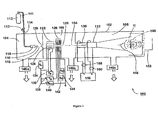
Figure 1 is a schematic view of a gas cluster ion beam processing system used for the present invention; -
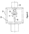
Figure 2 is an exploded view of a portion of the gas cluster ion beam processing system showing the workpiece holder; -
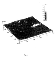
Figure 3 is an atomic force microscope image showing the surface of a coronary stent before GCIB processing; -
Figure 4 is an atomic force microscope image showing the surface of a coronary stent after GCIB processing; -
Figure 5 is a schematic view of a monomer ion beam processing system used for the present invention; -
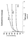
Figure 6A is a graph showing the release rate of fluorescence over time; and 1Figure 6B is a graph showing the cumulative release rate of fluorescence over time. - Beams of energetic ions, electrically charged atoms or molecules accelerated through high voltages under vacuum, are widely utilized to form semiconductor device junctions, to smooth surfaces by sputtering, and to enhance the properties of thin films. In the present invention, these same beams of energetic ions are utilized for the applying and adhering drugs to a surface of a medical device, such as a coronary stent.
- In the present invention, gas cluster ion beam (GCIB) processing is utilized. Gas cluster ions are formed from large numbers of weakly bound atoms or molecules sharing common electrical charges and accelerated together through high voltages to have high total energies. Cluster ions disintegrate upon impact and the total energy of the cluster is shared among the constituent atoms. Because of this energy sharing, the atoms are individually much less energetic than the case of conventional ions or ions not clustered together and, as a result, the atoms penetrate to much shorter depths. Surface sputtering effects are orders of magnitude stronger than corresponding effects produced by conventional ions, thereby making important microscale surface effects possible that are not possible in any other way.
- The concept of GCIB processing has only emerged over the past decade. Using a GCIB for dry etching, cleaning, and smoothing of materials is known in the art and has been described, for example, by
Deguchi, et al. in U.S, Patent No. 5,814,194 , "Substrate Surface Treatment Method", 1998. Because ionized clusters containing on the order of thousands of gas atoms or molecules may be formed and accelerated to modest energies on the order of a few thousands of electron volts, individual atoms or molecules in the clusters may each only have an average energy on the order of a few electron volts. It is known from the teachings of Yamada in, for example,U.S. Patent 5,459,326 , that such individual atoms are not energetic enough to significantly penetrate a surface to cause the residual sub-surface damage typically associated with plasma polishing. Nevertheless, the clusters themselves are sufficiently energetic (some thousands of electron volts) to effectively etch, smooth, or clean hard surfaces. - Because the energies of individual atoms within a gas cluster ion are very small, typically a few eV, the atoms penetrate through only a few atomic layers, at most, of a target surface during impact. This shallow penetration of the impacting atoms means all of the energy carried by the entire cluster ion is consequently dissipated in an extremely small volume in the top surface layer during a period on the order of 10-12 seconds (i.e. one picosecond). This is different from the case of ion implantation which is normally done with conventional monomer ions and where the intent is to penetrate into the material, sometimes penetrating several thousand angstroms, to produce changes in the surface properties of the material. Because of the high total energy of the cluster ion and extremely small interaction volume, the deposited energy density at the impact site is far greater than in the case of bombardment by conventional monomer ions.
- Reference is now made to
Figure 1 of the drawings which shows the gas cluster ion beam (GCIB)processor 100 utilized for applying or adhering drugs to the surface of acoronary stent 10, Although not limited to the specific components described herein, theprocessor 100 is made up of avacuum vessel 102 which is divided into three communicating chambers, asource chamber 104, an ionization/acceleration chamber 106, and aprocessing chamber 108 which includes therein a uniquely designedworkpiece holder 150 capable of positioning the medical device for uniform GCIB bombardment and drug application by a gas cluster ion beam. - During the drug application method of this invention, the three chambers are evacuated to suitable operating pressures by
vacuum pumping systems cylinder 111 is admitted under pressure throughgas metering valve 113 andgas feed tube 114 intostagnation chamber 116 and is ejected into the substantially lower pressure vacuum through a properly shapednozzle 110, resulting in asupersonic gas jet 118, Cooling, which results from the expansion in the jet, causes a portion of thegas jet 118 to condense into clusters, each consisting of from several to several thousand weakly bound atoms or molecules. Agas skimmer aperture 120 partially separates the gas molecules that have not condensed into a cluster jet from the cluster jet so as to minimize pressure in the downstream regions where such higher pressures would be detrimental (e.g.,ionizer 122,high voltage electrodes 126, and process chamber 108). Suitablecondensable source gases 112 include, but are not necessarily limited to argon, nitrogen, carbon dioxide, oxygen. - After the
supersonic gas jet 118 containing gas clusters has been formed, the clusters are ionized in anionizer 122, Theionizer 122 is typically an electron impact ionizer that produces thermoelectrons from one or moreincandescent filaments 124 and accelerates and directs the electrons causing them to collide with the gas clusters in thegas jet 118, where the jet passes through theionizer 122. The electron impact ejects electrons from the clusters, causing a portion the clusters to become positively ionized. A set of suitably biasedhigh voltage electrodes 126 extracts the cluster ions from theionizer 122, forming a beam, then accelerates the cluster ions to a desired energy (typically from 1 keV to several tens of keV) and focuses them to form aGCIB 128 having aninitial trajectory 154, Filament power supply 136 provides voltage VF to heat theionizer filament 124.Anode power supply 134 provides voltage VA to accelerate thermoelectrons emitted fromfilament 124 to cause them to bombard the cluster containinggas jet 118 to produce ions.Extraction power supply 138 provides voltage VE to bias a high voltage electrode to extract ions from the ionizing region ofionizer 122 and to form aGCIB 128.Accelerator power supply 140 provides voltage VAcc to bias a high voltage electrode with respect to theionizer 122 so as to result in a total GCIB acceleration energy equal to VAcc electron volts (eV). One or more lens power supplies (142 and 144, for example) may be provided to bias high voltage electrodes with potentials (VL1 and VL2 for example) to focus theGCIB 128. - A
medical device 10, such as a coronary stent, to be processed by theGCIB processor 100 is held on aworkpiece holder 150, and disposed in the path of theGCIB 128 for irradiation. The present invention may be utilized with medical devices composed of a variety of materials, such as metal, polyethylene, ceramic, or combinations thereof In order for the stent to be uniformly processed using GCIB, theworkpiece holder 150 is designed in a manner set forth below to manipulate thestent 10 in a specific way, - Referring now to
Figure 2 of the drawings, stent surfaces that are non-planar must remain oriented within a specific angle tolerance with respect to the normal beam incidence to obtain paramount effect to the stent surfaces utilizing GCIB. This requires a fixture orworkpiece holder 150 with the ability to be fully articulated to orient all non-planar surfaces ofstent 10 to be modified within that specific angle tolerance at a constant exposure level for process optimization and uniformity. Anystent 10 containing surfaces that would be exposed to the process beam at angles of greater than +/-15 degrees from normal incidence may require manipulation, More specifically, when applying GCIB to acoronary stent 10, theworkpiece holder 150 is rotated and articulated by amechanism 152 located at the end of theGCIB processor 100, The articulation/rotation mechanism 152 preferably permits 360 degrees of device rotation aboutlongitudinal axis 154 and sufficient device articulation about anaxis 156 perpendicular toaxis 154 to maintain the stent's surface to within +/-15 degrees from normal beam incidence. - Under certain conditions, depending upon the size of the
coronary stent 10, a scanning system may be desirable to produce uniform smoothness. Although not necessary for GCIB processing, two pairs of orthogonally orientedelectrostatic scan plates scan generator 156 provides X-axis and Y-axis scanning signal voltages to the pairs ofscan plates lead pairs GCIB 128 to be converted into a scannedGCIB 148, which scans the entire surface of thestent 10. - When beam scanning over an extended region is not desired, processing is generally confined to a region that is defined by the diameter of the beam. The diameter of the beam at the stent's surface can be set by selecting the voltages (VL1 and/or VL2) of one or more lens power supplies (142 and 144 shown for example) to provide the desired beam diameter at the workpiece.
- In one embodiment of the present invention, the surface of the medical device is irradiated with the gas cluster ion beam prior to the deposition of any drug on the surface thereof. This will remove any contaminants and oxide layers from the stent surface rendering the surface electrically active and capable of attracting and bonding drug molecules that are then introduced to the surface, One or more types of drugs are deposited upon surface through vapor phase deposition or by introducing a liquid form of the drug onto the surface. In some instances, the liquid form of the drug is in solution with a volatile solvent thereby requiring the solvent to be evaporated. As the formed mechanical bonds are broken over time, the drug is slowly released to the site of stent implantation.
- Studies have suggested that a wide variety of drugs may be useful at the site of contact between the medical device and the in vivo environment. For example, drugs such as anti-coagulants, anti-prolifics, antibiotics, immune-supressing agents, vasodilators, anti-thrombotic substances, anti-platelet substances, and cholesterol reducing agents may reduce instances af restenosis when diffused into the blood vessel wall after insertion of the stent.
- In yet another embodiment of the present invention, GCIB processing is utilized to impact the surface with energetic clusters thus implanting and forming a mechanical bond to the drug molecules of the medicine that had been applied in liquid form to coat the stent surface; or to implant the drug molecules of the electrostatically coated medicine in powder form to the stent surface in the same manner described above. The impact energy of the gas clusters results in a portion of the deposited drug molecules to form a carbon matrix at the surface. As the carbon matrix is formed, the remaining drug molecules become embedded within the interstices of the matrix. Over time, these drug molecules diffuse through the matrix and are released at the contact site between the stent and the blood vessel wall thereby continuously providing medication to the site.
- As the atomic force microscope (AFM) images shown in
Figures 3 and4 demonstrate, it is possible to dramatically affect the surface on stents utilizing one embodiment of the present invention,Figure 3 shows a stent before GCIB treatment with gross surface micro-roughness on a strut edge. The surface roughness measured an Ra of 113 angstroms and an RRMS of 148 angstroms. These irregularities highlight the surface condition at the cellular level where thrombosis begins.Figure 4 shows a stent after GCIB processing where the surface micro-roughness has been eliminated without any measurable physical or structural change to the integrity of the stent itself, The post-GCIB surface roughness measured an Ra of 19 angstroms and an RRMS of 25 angstroms. In this manner, GCIB processing also provides the added benefit of smoothing the surface of the medical device while applying/adhering the drug to the surface. Non-smooth surfaces may snare fibrinogen, platelets, and other matter further promoting stenosis to occur. - In still another embodiment of the present invention, monomer ion beam implantation is be used with the present invention when significant penetration of the drug into the surface of the medical device is desired. Because of the high energies associated with the individual atoms, implantation at increased depths may be achieved- As can be seen in
Figure 5 , in avacuum chamber 505, anion source material 500, such as boron trifluoride for boron ions, is extracted from; aplasma chamber 502 by electrostatic means, and focussed and accelerated to form an ion beam 507. Amass analysis device 501, such as a dipole sector magnet selects only the desired ion species, chosen to provide the desired chemical or physical effect upon implantation. The selected species is accelerated 503 to an energy chosen to give a very specific implant depth profile and irradiated into the surface of thestent 10 or other medical device held in place by theworkpiece holder 150. - As described above for GCIB processing, one or more drugs are deposited upon a surface of the medical device and the medical device is positioned within the path of the monomer ion beam such that the surface having the drug deposited thereon will be irradiated during processing More particularly, the workpiece holder described above is utilized due to the inherently non-planar design of the stent
- Now turning to
Figures 6A and6B , elution rates for a substance adhered to a surface of a coronary stent using GCIB processing in accordance with the present invention is shown To demonstrate the release rate of a molecule adhered to the surface in accordance with the present invention, the surface was irradiated and a flourescent organic dye was vapor deposited onto the freshly irradiated surface while the surface remained in the vacuum chamber The dye elution rate was measured by observing the flourescence of the elute as a function of time. InFigure 6A , the release rate is shown over time. InFigure 6B , the cumulative release rate is shown over time. - Although the invention has been described with respect to various embodiments, it should be realized this invention is also capable of a wide variety of further and other embodiments within the scope of the appended claims.
Claims (8)
- A medical device (10) with an irradiated surface having a drug delivery coating comprising a drug embedded within the interstices of a carbon matrix layer covering at least a portion of the surface for controlling drug release rate, and wherein the matrix layer consists of gas cluster ion beam irradiated material formed from the drug, and, further, wherein the drug is adhered to the surface without a polymer or other binding agent.
- The medical device (10) of claim 1, wherein the matrix material is ion-irradiated drug.
- The medical device of claim 1, wherein the drug comprises molecules that diffuse through the matrix and are released over time.
- The medical device (10) of claim 1, wherein the medical device (10) is a stent.
- The medical device (10) of claim 1, wherein the carbon matrix comprises carbon from irradiated drug molecules.
- The medical device (10) of claim 4, wherein the drug delivery coating is, in use, positioned to contact a blood vessel wall when the stent is positioned within the blood vessel.
- The medical device (10) of any of claims 1 through 6, wherein the drug is selected from the group consisting of anti-coagulants, antibiotics, immune-suppressing agents, vasodilators, anti-thrombotic substances, anti-platelet substances, cholesterol reducing agents and combinations thereof.
- The medical device of any of claims 1 through 7, wherein the medical device is composed of a metal, polyethylene, ceramic, or combinations thereof.
Applications Claiming Priority (3)
| Application Number | Priority Date | Filing Date | Title |
|---|---|---|---|
| US29038901P | 2001-05-11 | 2001-05-11 | |
| US31765201P | 2001-09-06 | 2001-09-06 | |
| EP02769731A EP1393601B1 (en) | 2001-05-11 | 2002-05-13 | Method for improving the effectiveness of medical devices by adhering drugs to the surface thereof |
Related Parent Applications (2)
| Application Number | Title | Priority Date | Filing Date |
|---|---|---|---|
| EP02769731A Division EP1393601B1 (en) | 2001-05-11 | 2002-05-13 | Method for improving the effectiveness of medical devices by adhering drugs to the surface thereof |
| EP02769731.7 Division | 2002-05-13 |
Publications (2)
| Publication Number | Publication Date |
|---|---|
| EP2210626A1 EP2210626A1 (en) | 2010-07-28 |
| EP2210626B1 true EP2210626B1 (en) | 2015-01-21 |
Family
ID=26966151
Family Applications (2)
| Application Number | Title | Priority Date | Filing Date |
|---|---|---|---|
| EP10158600.6A Expired - Lifetime EP2210626B1 (en) | 2001-05-11 | 2002-05-13 | Medical devices having drugs adhered to the surface thereof. |
| EP02769731A Expired - Lifetime EP1393601B1 (en) | 2001-05-11 | 2002-05-13 | Method for improving the effectiveness of medical devices by adhering drugs to the surface thereof |
Family Applications After (1)
| Application Number | Title | Priority Date | Filing Date |
|---|---|---|---|
| EP02769731A Expired - Lifetime EP1393601B1 (en) | 2001-05-11 | 2002-05-13 | Method for improving the effectiveness of medical devices by adhering drugs to the surface thereof |
Country Status (5)
| Country | Link |
|---|---|
| US (1) | US7105199B2 (en) |
| EP (2) | EP2210626B1 (en) |
| JP (1) | JP4617060B2 (en) |
| DE (1) | DE60237813D1 (en) |
| WO (1) | WO2002093988A1 (en) |
Families Citing this family (83)
| Publication number | Priority date | Publication date | Assignee | Title |
|---|---|---|---|---|
| US7713297B2 (en) | 1998-04-11 | 2010-05-11 | Boston Scientific Scimed, Inc. | Drug-releasing stent with ceramic-containing layer |
| US8889169B2 (en) * | 2001-05-11 | 2014-11-18 | Exogenesis Corporation | Drug delivery system and method of manufacturing thereof |
| US7923055B2 (en) * | 2001-05-11 | 2011-04-12 | Exogenesis Corporation | Method of manufacturing a drug delivery system |
| US7666462B2 (en) * | 2001-05-11 | 2010-02-23 | Exogenesis Corporation | Method of controlling a drug release rate |
| US20090074834A1 (en) * | 2007-09-14 | 2009-03-19 | Exogenesis Corporation | Method and system for modifying the wettability characteristics of a surface of a medical device by the application of gas cluster ion beam technology and medical devices made thereby |
| AU2002345328A1 (en) | 2001-06-27 | 2003-03-03 | Remon Medical Technologies Ltd. | Method and device for electrochemical formation of therapeutic species in vivo |
| EP2253339B1 (en) | 2003-02-21 | 2011-12-28 | Sorin Biomedica Cardio S.r.l. | A process for producing stents and corresponding stent |
| US20050131513A1 (en) * | 2003-12-16 | 2005-06-16 | Cook Incorporated | Stent catheter with a permanently affixed conductor |
| EP2505166B1 (en) | 2005-04-04 | 2017-07-12 | Flexible Stenting Solutions, Inc. | Flexible stent |
| US20060233941A1 (en) * | 2005-04-15 | 2006-10-19 | Boston Scientific Scimed, Inc. | Method of coating a medical device utilizing an ion-based thin film deposition technique, a system for coating a medical device, and a medical device produced by the method |
| US8840660B2 (en) | 2006-01-05 | 2014-09-23 | Boston Scientific Scimed, Inc. | Bioerodible endoprostheses and methods of making the same |
| US8089029B2 (en) | 2006-02-01 | 2012-01-03 | Boston Scientific Scimed, Inc. | Bioabsorbable metal medical device and method of manufacture |
| US20070224235A1 (en) | 2006-03-24 | 2007-09-27 | Barron Tenney | Medical devices having nanoporous coatings for controlled therapeutic agent delivery |
| US8187620B2 (en) | 2006-03-27 | 2012-05-29 | Boston Scientific Scimed, Inc. | Medical devices comprising a porous metal oxide or metal material and a polymer coating for delivering therapeutic agents |
| US8048150B2 (en) | 2006-04-12 | 2011-11-01 | Boston Scientific Scimed, Inc. | Endoprosthesis having a fiber meshwork disposed thereon |
| US8815275B2 (en) | 2006-06-28 | 2014-08-26 | Boston Scientific Scimed, Inc. | Coatings for medical devices comprising a therapeutic agent and a metallic material |
| US8771343B2 (en) | 2006-06-29 | 2014-07-08 | Boston Scientific Scimed, Inc. | Medical devices with selective titanium oxide coatings |
| CA2659761A1 (en) | 2006-08-02 | 2008-02-07 | Boston Scientific Scimed, Inc. | Endoprosthesis with three-dimensional disintegration control |
| WO2008033711A2 (en) | 2006-09-14 | 2008-03-20 | Boston Scientific Limited | Medical devices with drug-eluting coating |
| JP2010503491A (en) | 2006-09-15 | 2010-02-04 | ボストン サイエンティフィック リミテッド | Bioerodible endoprosthesis with biologically stable inorganic layers |
| WO2008034031A2 (en) | 2006-09-15 | 2008-03-20 | Boston Scientific Limited | Bioerodible endoprostheses and methods of making the same |
| ATE517590T1 (en) | 2006-09-15 | 2011-08-15 | Boston Scient Ltd | BIOLOGICALLY ERODABLE ENDOPROTHESES |
| US8052744B2 (en) | 2006-09-15 | 2011-11-08 | Boston Scientific Scimed, Inc. | Medical devices and methods of making the same |
| WO2008036548A2 (en) | 2006-09-18 | 2008-03-27 | Boston Scientific Limited | Endoprostheses |
| US7981150B2 (en) | 2006-11-09 | 2011-07-19 | Boston Scientific Scimed, Inc. | Endoprosthesis with coatings |
| ATE488259T1 (en) | 2006-12-28 | 2010-12-15 | Boston Scient Ltd | BIOERODIBLE ENDOPROTHES AND PRODUCTION METHODS THEREOF |
| US8431149B2 (en) | 2007-03-01 | 2013-04-30 | Boston Scientific Scimed, Inc. | Coated medical devices for abluminal drug delivery |
| US8070797B2 (en) | 2007-03-01 | 2011-12-06 | Boston Scientific Scimed, Inc. | Medical device with a porous surface for delivery of a therapeutic agent |
| US8067054B2 (en) * | 2007-04-05 | 2011-11-29 | Boston Scientific Scimed, Inc. | Stents with ceramic drug reservoir layer and methods of making and using the same |
| US7976915B2 (en) | 2007-05-23 | 2011-07-12 | Boston Scientific Scimed, Inc. | Endoprosthesis with select ceramic morphology |
| US7942926B2 (en) | 2007-07-11 | 2011-05-17 | Boston Scientific Scimed, Inc. | Endoprosthesis coating |
| US8002823B2 (en) | 2007-07-11 | 2011-08-23 | Boston Scientific Scimed, Inc. | Endoprosthesis coating |
| JP2010533563A (en) | 2007-07-19 | 2010-10-28 | ボストン サイエンティフィック リミテッド | Endoprosthesis with adsorption inhibiting surface |
| US8815273B2 (en) | 2007-07-27 | 2014-08-26 | Boston Scientific Scimed, Inc. | Drug eluting medical devices having porous layers |
| US7931683B2 (en) | 2007-07-27 | 2011-04-26 | Boston Scientific Scimed, Inc. | Articles having ceramic coated surfaces |
| US8221822B2 (en) | 2007-07-31 | 2012-07-17 | Boston Scientific Scimed, Inc. | Medical device coating by laser cladding |
| US7988723B2 (en) | 2007-08-02 | 2011-08-02 | Flexible Stenting Solutions, Inc. | Flexible stent |
| JP2010535541A (en) | 2007-08-03 | 2010-11-25 | ボストン サイエンティフィック リミテッド | Coating for medical devices with large surface area |
| US8052745B2 (en) | 2007-09-13 | 2011-11-08 | Boston Scientific Scimed, Inc. | Endoprosthesis |
| US20100227523A1 (en) * | 2007-09-14 | 2010-09-09 | Exogenesis Corporation | Methods for improving the bioactivity characteristics of a surface and objects with surfaces improved thereby |
| US8377460B2 (en) * | 2007-09-14 | 2013-02-19 | Exogenesis Corporation | Method for modifying the wettability and/or other biocompatibility characteristics of a surface of a biological material by the application of gas cluster ion beam technology and biological materials made thereby |
| US9144627B2 (en) | 2007-09-14 | 2015-09-29 | Exogenesis Corporation | Methods for improving the bioactivity characteristics of a surface and objects with surfaces improved thereby |
| EP2192993A4 (en) * | 2007-10-01 | 2012-02-15 | Exogenesis Corp | Method and system for coating a surface of a medical device with a therapeutic agent and drug eluting medical devices made thereby |
| US7938855B2 (en) | 2007-11-02 | 2011-05-10 | Boston Scientific Scimed, Inc. | Deformable underlayer for stent |
| US8029554B2 (en) | 2007-11-02 | 2011-10-04 | Boston Scientific Scimed, Inc. | Stent with embedded material |
| US8216632B2 (en) | 2007-11-02 | 2012-07-10 | Boston Scientific Scimed, Inc. | Endoprosthesis coating |
| US20090186068A1 (en) * | 2008-01-18 | 2009-07-23 | Chameleon Scientific Corporation | Atomic plasma deposited coatings for drug release |
| WO2009102564A2 (en) * | 2008-02-11 | 2009-08-20 | Boston Scientific Scimed, Inc. | Substrate coating apparatus having a solvent vapor emitter |
| WO2009131911A2 (en) | 2008-04-22 | 2009-10-29 | Boston Scientific Scimed, Inc. | Medical devices having a coating of inorganic material |
| US8932346B2 (en) | 2008-04-24 | 2015-01-13 | Boston Scientific Scimed, Inc. | Medical devices having inorganic particle layers |
| US7998192B2 (en) | 2008-05-09 | 2011-08-16 | Boston Scientific Scimed, Inc. | Endoprostheses |
| US8236046B2 (en) | 2008-06-10 | 2012-08-07 | Boston Scientific Scimed, Inc. | Bioerodible endoprosthesis |
| EP2303350A2 (en) | 2008-06-18 | 2011-04-06 | Boston Scientific Scimed, Inc. | Endoprosthesis coating |
| US7985252B2 (en) | 2008-07-30 | 2011-07-26 | Boston Scientific Scimed, Inc. | Bioerodible endoprosthesis |
| JP2011530347A (en) * | 2008-08-07 | 2011-12-22 | エクソジェネシス コーポレーション | Drug delivery system and method of manufacturing the drug delivery system |
| EP2326356B1 (en) * | 2008-08-07 | 2017-10-11 | Exogenesis Corporation | Medical device for bone implant and method for producing such a device |
| US8382824B2 (en) | 2008-10-03 | 2013-02-26 | Boston Scientific Scimed, Inc. | Medical implant having NANO-crystal grains with barrier layers of metal nitrides or fluorides |
| US9149376B2 (en) | 2008-10-06 | 2015-10-06 | Cordis Corporation | Reconstrainable stent delivery system |
| US8231980B2 (en) | 2008-12-03 | 2012-07-31 | Boston Scientific Scimed, Inc. | Medical implants including iridium oxide |
| WO2010101901A2 (en) | 2009-03-02 | 2010-09-10 | Boston Scientific Scimed, Inc. | Self-buffering medical implants |
| US8071156B2 (en) | 2009-03-04 | 2011-12-06 | Boston Scientific Scimed, Inc. | Endoprostheses |
| US20100233227A1 (en) * | 2009-03-10 | 2010-09-16 | Boston Scientific Scimed, Inc. | Medical devices having carbon drug releasing layers |
| JP2012520143A (en) * | 2009-03-11 | 2012-09-06 | エクソジェネシス コーポレーション | Method for modifying wettability and / or other biocompatibility properties of biological material surfaces by application of gas cluster ion beam technology and manufactured biological materials |
| CN102348430B (en) * | 2009-03-11 | 2017-09-01 | 艾克索乔纳斯公司 | Improve the method for surface bioactive feature and the object with the surface thus improved |
| US8287937B2 (en) | 2009-04-24 | 2012-10-16 | Boston Scientific Scimed, Inc. | Endoprosthese |
| WO2011119573A1 (en) | 2010-03-23 | 2011-09-29 | Boston Scientific Scimed, Inc. | Surface treated bioerodible metal endoprostheses |
| WO2012001325A2 (en) * | 2010-07-02 | 2012-01-05 | Valois Sas | Method for the surface treatment of a fluid product dispensing device |
| US10181402B2 (en) | 2010-08-23 | 2019-01-15 | Exogenesis Corporation | Method and apparatus for neutral beam processing based on gas cluster ion beam technology and articles produced thereby |
| US10202684B2 (en) | 2010-08-23 | 2019-02-12 | Exogenesis Corporation | Method for neutral beam processing based on gas cluster ion beam technology and articles produced thereby |
| CN103180030B (en) | 2010-08-23 | 2017-04-12 | 艾克索乔纳斯公司 | Method and apparatus for neutral beam processing based on gas cluster ion beam technology |
| US11199769B2 (en) | 2010-08-23 | 2021-12-14 | Exogenesis Corporation | Method and apparatus for neutral beam processing based on gas cluster ion beam technology |
| US20170303383A1 (en) * | 2010-08-23 | 2017-10-19 | Exogenesis Corporation | Method for neutral beam processing based on gas cluster ion beam technology and articles produced thereby |
| US9799488B2 (en) * | 2010-08-23 | 2017-10-24 | Exogenesis Corporation | Method and apparatus for neutral beam processing based on gas cluster ion beam technology |
| US10825685B2 (en) | 2010-08-23 | 2020-11-03 | Exogenesis Corporation | Method for neutral beam processing based on gas cluster ion beam technology and articles produced thereby |
| US10670960B2 (en) | 2010-08-23 | 2020-06-02 | Exogenesis Corporation | Enhanced high aspect ratio etch performance using accelerated neutral beams derived from gas-cluster ion beams |
| US10556042B2 (en) | 2011-08-19 | 2020-02-11 | Exogenesis Corporation | Drug delivery system and method of manufacturing thereof |
| US20140236286A1 (en) * | 2011-08-19 | 2014-08-21 | Sean R. Kirkpatrick | Drug delivery system and method of manufacturing thereof |
| CA2845762C (en) * | 2011-08-22 | 2019-01-08 | Exogenesis Corporation | Drug delivery system and method of manufacturing thereof |
| US9114195B2 (en) | 2011-08-22 | 2015-08-25 | Exogenesis Corporation | Method for modifying the wettability and other biocompatibility characteristics of a surface of a biological material by the application of beam technology and biological materials made thereby |
| EP2758184A4 (en) | 2011-08-22 | 2015-06-24 | Exogenesis Corp | Methods for improving the bioactivity characteristics of a surface and objects with surfaces improved thereby |
| RU2648961C2 (en) * | 2012-02-22 | 2018-03-28 | Эксодженезис Корпорейшн | Method for processing the beam of neutral particles based on the technology for processing the beam of gas cluster ions and obtained by such as a product |
| GB2546319B (en) | 2016-01-15 | 2019-07-03 | Cook Medical Technologies Llc | Coated medical device and method of coating such a device |
| CA3208941A1 (en) * | 2021-01-22 | 2022-07-28 | Exogenesis Corporation | Accelerated neutral atom beam (anab) modified polypropylene for reducing bacteria colonization without antibiotics |
Family Cites Families (20)
| Publication number | Priority date | Publication date | Assignee | Title |
|---|---|---|---|---|
| US4968006A (en) * | 1989-07-21 | 1990-11-06 | Spire Corporation | Ion implantation of spherical surfaces |
| US5123924A (en) | 1990-04-25 | 1992-06-23 | Spire Corporation | Surgical implants and method |
| JP2662321B2 (en) | 1991-05-31 | 1997-10-08 | 科学技術振興事業団 | Surface treatment method using ultra-slow cluster ion beam |
| US5419760A (en) * | 1993-01-08 | 1995-05-30 | Pdt Systems, Inc. | Medicament dispensing stent for prevention of restenosis of a blood vessel |
| US5814194A (en) | 1994-10-20 | 1998-09-29 | Matsushita Electric Industrial Co., Ltd | Substrate surface treatment method |
| US5837313A (en) * | 1995-04-19 | 1998-11-17 | Schneider (Usa) Inc | Drug release stent coating process |
| US5609629A (en) * | 1995-06-07 | 1997-03-11 | Med Institute, Inc. | Coated implantable medical device |
| JP3770970B2 (en) * | 1996-08-28 | 2006-04-26 | 昭和ゴム株式会社 | Surface treatment method of medical article by argon gas cluster ion beam |
| US5843172A (en) * | 1997-04-15 | 1998-12-01 | Advanced Cardiovascular Systems, Inc. | Porous medicated stent |
| US6331227B1 (en) | 1999-12-14 | 2001-12-18 | Epion Corporation | Enhanced etching/smoothing of dielectric surfaces |
| US20020017454A1 (en) * | 2000-07-10 | 2002-02-14 | Epion Corporation | Method and system for improving the effectiveness of intraocular lenses by the application of gas cluster ion beam technology |
| WO2002004696A1 (en) * | 2000-07-10 | 2002-01-17 | Epion Corporation | Improving effectiveness of artificial hip by gcib |
| US6676989B2 (en) * | 2000-07-10 | 2004-01-13 | Epion Corporation | Method and system for improving the effectiveness of medical stents by the application of gas cluster ion beam technology |
| US6716444B1 (en) * | 2000-09-28 | 2004-04-06 | Advanced Cardiovascular Systems, Inc. | Barriers for polymer-coated implantable medical devices and methods for making the same |
| US6641607B1 (en) * | 2000-12-29 | 2003-11-04 | Advanced Cardiovascular Systems, Inc. | Double tube stent |
| US6635082B1 (en) * | 2000-12-29 | 2003-10-21 | Advanced Cardiovascular Systems Inc. | Radiopaque stent |
| US7077982B2 (en) * | 2001-03-23 | 2006-07-18 | Fuji Photo Film Co., Ltd. | Molecular electric wire, molecular electric wire circuit using the same and process for producing the molecular electric wire circuit |
| US6764505B1 (en) | 2001-04-12 | 2004-07-20 | Advanced Cardiovascular Systems, Inc. | Variable surface area stent |
| EP1392200B1 (en) * | 2001-05-09 | 2011-10-12 | Exogenesis Corporation | Method for improving the effectiveness of artificial joints by the application of gas cluster ion beam technology |
| US20050025804A1 (en) * | 2003-07-28 | 2005-02-03 | Adam Heller | Reduction of adverse inflammation |
-
2002
- 2002-05-13 US US10/144,919 patent/US7105199B2/en not_active Expired - Lifetime
- 2002-05-13 WO PCT/US2002/015236 patent/WO2002093988A1/en not_active Ceased
- 2002-05-13 EP EP10158600.6A patent/EP2210626B1/en not_active Expired - Lifetime
- 2002-05-13 DE DE60237813T patent/DE60237813D1/en not_active Expired - Lifetime
- 2002-05-13 JP JP2002590721A patent/JP4617060B2/en not_active Expired - Fee Related
- 2002-05-13 EP EP02769731A patent/EP1393601B1/en not_active Expired - Lifetime
Also Published As
| Publication number | Publication date |
|---|---|
| US20020188324A1 (en) | 2002-12-12 |
| JP4617060B2 (en) | 2011-01-19 |
| EP1393601A1 (en) | 2004-03-03 |
| US7105199B2 (en) | 2006-09-12 |
| EP1393601A4 (en) | 2007-03-21 |
| EP1393601B1 (en) | 2010-09-29 |
| DE60237813D1 (en) | 2010-11-11 |
| JP2004532081A (en) | 2004-10-21 |
| WO2002093988A1 (en) | 2002-11-21 |
| EP2210626A1 (en) | 2010-07-28 |
Similar Documents
| Publication | Publication Date | Title |
|---|---|---|
| EP1393601B1 (en) | Method for improving the effectiveness of medical devices by adhering drugs to the surface thereof | |
| EP1986791B9 (en) | Drug delivery system and method of manufacturing thereof | |
| US8187662B2 (en) | Method of controlling a drug release rate | |
| JP2008080143A (en) | Medical apparatus | |
| US10342900B2 (en) | Drug delivery system and method of manufacturing thereof | |
| AU2016204279B2 (en) | Drug Delivery System and Method of Manufacturing Thereof | |
| US20190171098A1 (en) | Drug delivery system and method of manufacturing thereof | |
| US10556042B2 (en) | Drug delivery system and method of manufacturing thereof | |
| US20180090295A1 (en) | Drug delivery system and method of manufacturing thereof |
Legal Events
| Date | Code | Title | Description |
|---|---|---|---|
| PUAI | Public reference made under article 153(3) epc to a published international application that has entered the european phase |
Free format text: ORIGINAL CODE: 0009012 |
|
| AC | Divisional application: reference to earlier application |
Ref document number: 1393601 Country of ref document: EP Kind code of ref document: P |
|
| AK | Designated contracting states |
Kind code of ref document: A1 Designated state(s): DE FR GB |
|
| 17P | Request for examination filed |
Effective date: 20110128 |
|
| 17Q | First examination report despatched |
Effective date: 20110328 |
|
| GRAP | Despatch of communication of intention to grant a patent |
Free format text: ORIGINAL CODE: EPIDOSNIGR1 |
|
| INTG | Intention to grant announced |
Effective date: 20140526 |
|
| GRAS | Grant fee paid |
Free format text: ORIGINAL CODE: EPIDOSNIGR3 |
|
| GRAP | Despatch of communication of intention to grant a patent |
Free format text: ORIGINAL CODE: EPIDOSNIGR1 |
|
| GRAA | (expected) grant |
Free format text: ORIGINAL CODE: 0009210 |
|
| INTG | Intention to grant announced |
Effective date: 20141211 |
|
| AC | Divisional application: reference to earlier application |
Ref document number: 1393601 Country of ref document: EP Kind code of ref document: P |
|
| AK | Designated contracting states |
Kind code of ref document: B1 Designated state(s): DE FR GB |
|
| REG | Reference to a national code |
Ref country code: GB Ref legal event code: FG4D |
|
| REG | Reference to a national code |
Ref country code: DE Ref legal event code: R096 Ref document number: 60246938 Country of ref document: DE Effective date: 20150305 |
|
| REG | Reference to a national code |
Ref country code: DE Ref legal event code: R097 Ref document number: 60246938 Country of ref document: DE |
|
| PLBE | No opposition filed within time limit |
Free format text: ORIGINAL CODE: 0009261 |
|
| STAA | Information on the status of an ep patent application or granted ep patent |
Free format text: STATUS: NO OPPOSITION FILED WITHIN TIME LIMIT |
|
| 26N | No opposition filed |
Effective date: 20151022 |
|
| REG | Reference to a national code |
Ref country code: FR Ref legal event code: PLFP Year of fee payment: 15 |
|
| REG | Reference to a national code |
Ref country code: FR Ref legal event code: PLFP Year of fee payment: 16 |
|
| PGFP | Annual fee paid to national office [announced via postgrant information from national office to epo] |
Ref country code: FR Payment date: 20200525 Year of fee payment: 19 Ref country code: DE Payment date: 20200528 Year of fee payment: 19 |
|
| PGFP | Annual fee paid to national office [announced via postgrant information from national office to epo] |
Ref country code: GB Payment date: 20200527 Year of fee payment: 19 |
|
| REG | Reference to a national code |
Ref country code: DE Ref legal event code: R119 Ref document number: 60246938 Country of ref document: DE |
|
| GBPC | Gb: european patent ceased through non-payment of renewal fee |
Effective date: 20210513 |
|
| PG25 | Lapsed in a contracting state [announced via postgrant information from national office to epo] |
Ref country code: GB Free format text: LAPSE BECAUSE OF NON-PAYMENT OF DUE FEES Effective date: 20210513 Ref country code: DE Free format text: LAPSE BECAUSE OF NON-PAYMENT OF DUE FEES Effective date: 20211201 |
|
| PG25 | Lapsed in a contracting state [announced via postgrant information from national office to epo] |
Ref country code: FR Free format text: LAPSE BECAUSE OF NON-PAYMENT OF DUE FEES Effective date: 20210531 |